


Abstract
This paper presents a measurement-based framework for studying and mitigating control interactions between power system stabilizers (PSSs) and HVDC modulation damping controllers in hybrid AC/DC systems. Using frequency-response data obtained from small-signal injections, the method embeds driving-point and transfer impedance directly into the control loops, eliminating reliance on simplified analytical models. A lightweight optimizer adjusts controller gains and lead–lag angles to enhance damping at the inter-area mode while ensuring HVDC-to-PSS dominance, magnitude-crossing consistency, and a minimum damping margin across the 0.3–1.5 Hz band. The approach, implemented in ETAP 16.0 and MATLAB R2024a (MathWorks, Natick, MA, USA), successfully improves damping and maintains stability under all tested conditions, providing a practical co-design strategy for coordinated PSS–HVDC control in weakly interconnected networks.
1. Introduction
Low-frequency electromechanical oscillations (≈0.1–2 Hz) remain a limiting factor for transfer capability and security in large-scale power systems. Two primary damping mechanisms are widely deployed in parallel: generator-based power system stabilizers (PSSs), which enhance synchronizing torque through excitation control, and HVDC Modulation Supplementary Damping Controllers (MSDCs), which regulate active-power flow via converter control. Although each is effective individually, their concurrent operation can lead to control interaction, manifesting as competing damping torques or reinforcement of adverse components—particularly around inter-area modes and under changing network conditions [1,2,3,4,5]. Classical small-signal design techniques based on simplified analytical models often fail to capture these effects with sufficient fidelity.
The foundational role of excitation control was established by De Mello and Concordia [1] and consolidated in Kundur’s seminal text [2]. On the DC side, Larsen and Piwko [3,4] demonstrated that supplementary HVDC modulation effectively damps inter-area and sub synchronous oscillations, leading to its widespread adoption. With growing integration of inverter-based resources, modern surveys emphasize that robustness and coordinated design have become central challenges [5,6]. Field experience reinforces this view: PSS–HVDC interaction phenomena have been documented in the Nordic grid [7], Hydro-Québec [8], and large Chinese multi-infeed HVDC systems [9,10,11], underscoring their operational significance.
To overcome modeling limitations, measurement-based frequency-response approaches have gained prominence. Techniques using impedance and frequency-response data (FRD) capture the dynamic environment “as seen” by controllers, making magnitude and phase relationships explicit [12,13,14], while spectral estimation methods such as the Matrix Pencil Method provide high-resolution modal characterization [15]. Nevertheless, most PSS and HVDC designs remain independently tuned and only heuristically validated through simulation. Eigenvalue analysis, though insightful, depends on reduced models sensitive to operating points, whereas EMT-type simulations offer accuracy at the cost of heavy computation [5,16]. While model-based approaches rely on linearized representations around operating points, measurement-based frequency-response methods capture the actual small-signal environment perceived by each controller, thus offering a more reliable basis for coordinated tuning.
This paper introduces an FRD-native interaction framework that directly embeds measured driving-point and transfer impedances within the controller loops, evaluates aggregate interaction across the electromechanical band, and tunes gains and phase-lead parameters under explicit coordination policies. The proposed measurement-anchored workflow, combining ETAP 16.0 perturbation tests with MATLAB R2024a (MathWorks, Natick, MA, USA), frequency-domain post-processing, provides a reproducible path for co-designing PSS and HVDC controllers. Its effectiveness is demonstrated on Kundur’s two-area benchmark system.
2. Background Methods
The µ-synthesis framework (based on structured singular value) was used to design a feedback controller that minimizes the maximum singular values of the transfer matrix from disturbance to performance output [17].
For all admissible uncertainties to guarantee robust stability and performance over defined uncertainty, the HVDC and AC system were separated as subsystems and a decentralized controller was designed with the help of the Homotopy method to solve the non-convex bilinear system using a convex optimization method. Although μ-synthesis provides formal robustness guarantees, its resulting controllers are often of a high order and lack transparent physical interpretation. In contrast, the proposed frequency-response formulation retains the classical PSS/HVDC structure while embedding measured plant behavior directly in the design loop.
3. Interaction Framework
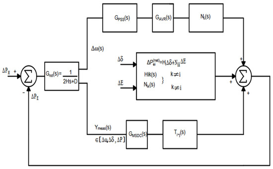
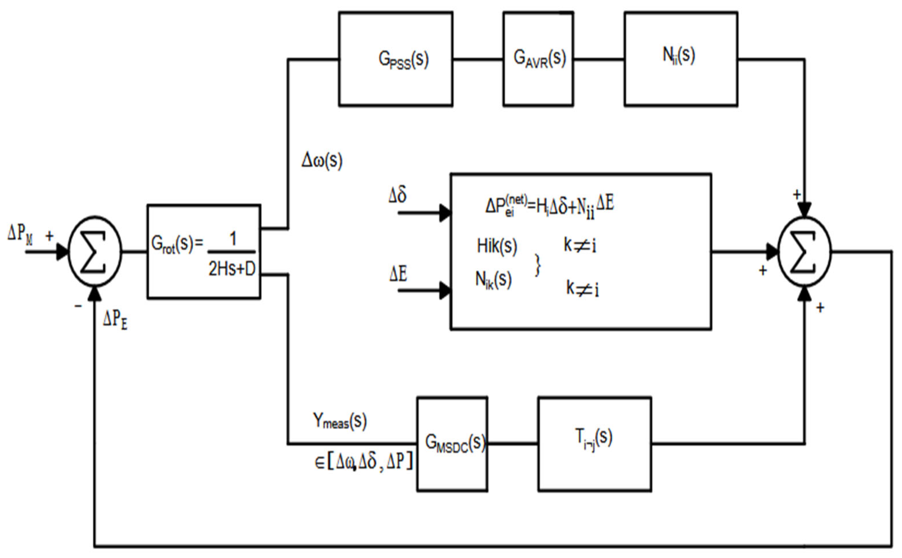
While model-based approaches rely on linearized representations around operating points, measurement-based frequency-response methods capture the actual small-signal environment perceived by each controller, thus offering a more reliable basis for coordinated tuning. The proposed method to study control interaction problems between HVDC MSDC and PSS in this text is explained with the help of Figure 1, which presents the small-signal interaction framework of a synchronous generator equipped with a PSS and Automatic Voltage Regulator (AVR), operating in parallel with an HVDC MSDC. This diagram captures the multiple feedback loops that jointly determine the damping of electromechanical oscillations. The total incremental electrical power at the generator bus can be expressed as a superposition of PSS and HVDC MSDC channels as
where the first term represents the PSS contribution through the excitation path with
and
representing exciter/field and PSS with speed input transfer functions respectively. The second term represents the HVDC MSDC contribution through the converter path with representing the HVDC path transfers driven by an arbitrary input . The other terms in (2) are not in either path.
Figure 1.
Control interaction framework.
Prior to , the first term, , captures the through-current effect, i.e., the change in real power due to scaling the existing current at fixed network conditions. The second term, , accounts for the network-conductance contribution, reflecting how the injected current itself varies with local voltage magnitude through the driving-point admittance. This compact expression is the complex-form equivalent of the element in the classical power-flow Jacobian, and when is replaced by the dynamic admittance, it generalizes the Jacobian entry to the frequency domain for small-signal or impedance-based interaction studies.
The transfer sensitivity quantifies the incremental change in real-power injection at bus resulting from a small perturbation in voltage magnitude at bus j. It is defined as
where is the steady-state current injection at bus , is the complex transfer impedance between buses i and j, and are the voltage magnitude and angle at bus j, and denotes the real-part operator. This term represents the cross-coupling channel (bus j → bus i) used to model power system stabilizer (PSS) and HVDC modulation interactions in the small-signal framework. The driving-point and transfer impedances were calculated according to Algorithm 1.
| Algorithm 1. Measuring Maximum Driving Point and Transfer Impedances |
| Step 1: Inject current at examining point (bus or generator terminal) in ETAP. Step 2: Take the voltage recordings at the generator terminal and current injections in the line. Step 3: Calculate and from the measured signal at the frequency of the injected signal using spectral analysis with the help of Matrix Pencil Method (MPM) Step 4: Calculate and |
4. Measurements and Controller Optimization
4.1. Frequency Scanning Technique to Determine and
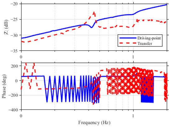
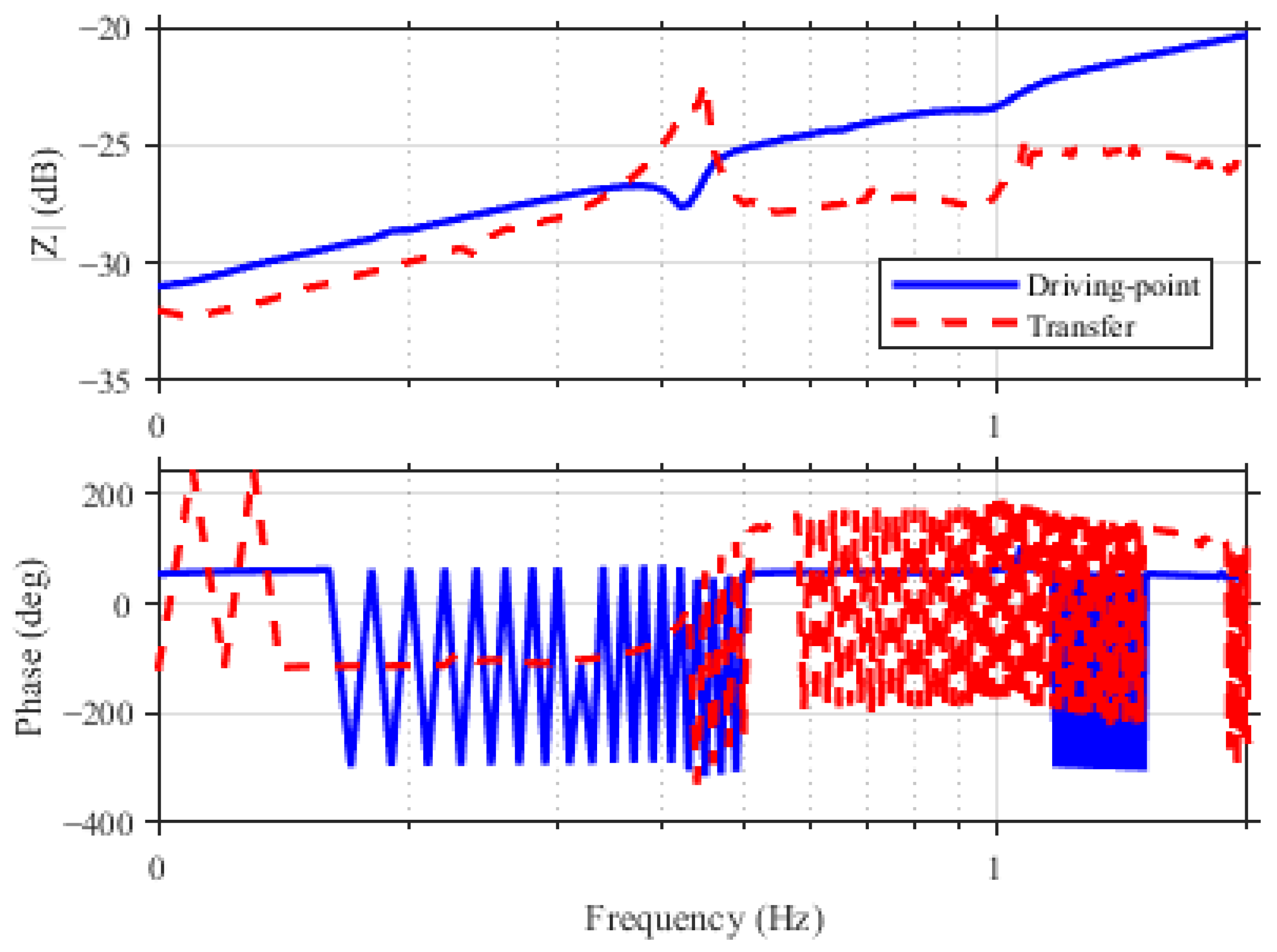
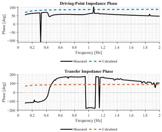
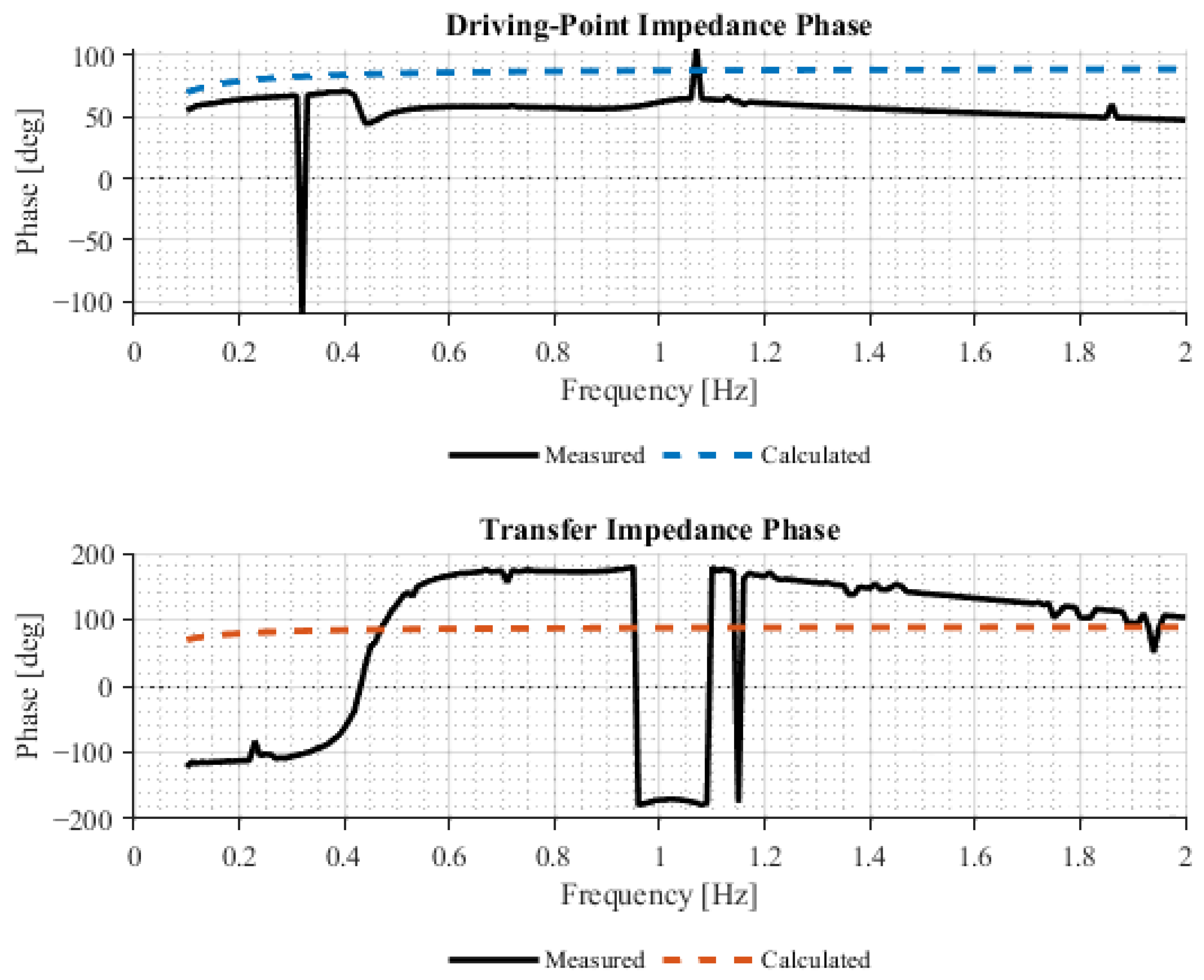
Figure 2 shows and magnitudes and phases which were obtained from implementing Algorithm 1 on a modified Kundur model in [18]. Current injections were done on the summing junction of generator gen 2 and rectifier current controller for driving-point and transfer impedance calculations respectively. The results obtained from the ETAP–MATLAB framework show strong agreement with those predicted by the classical Kron’s method for evaluating driving-point and transfer impedances as shown in Figure 3. The phase angle difference between the measured and calculated results are closely related. The differences are attributable to modeling errors and the fact that the calculation did not consider the HVDC system’s detailed measurements and optimization.
Figure 2.
Measured and magnitude and phase.
Figure 3.
Comparison between calculated and measured impedance phase angles.
4.2. Proposed Optimization of PSS and HVDC MSDC
The goal is to tune the PSS and HVDC MSDC compensation so that the combined loop
delivers positive damping at the target inter-area mode , while ensuring PSS dominance near and acceptable behavior over a wide band. Where and are open loop transfer functions of the PSS and HVDC MSDC path in Figure 1 respectively. This goal can be achieved by minimizing the impedances in a simplified network cost function as given in (6);
where: (damping proxy), at (control dominance), is the first crossing where , is the band floor and is the hinge
This cost function was optimized with the help of Algorithm 2. In this Algorithm, the lead angles and controller gains are initialized. The leads are initialized at centers by computing that roughly phase-align each path with at its center (from FRD phase). Taking for example the uncompensated base path then the phase lead was chosen such that
This makes the lead compensator contribute the phase deficiency needed to reach at the center frequency for the negative feedback system. This phase is given in degrees and in Hz; the phase lead compensator can be derived from (8):
This makes the maximum phase lead of equal to attained at:
The gains were initialized by “local loop normalization” which means picking each loop’s scalar gain so that its own open loop magnitude is one or 0 dB at its chosen center frequency. Equation (10) can find the initial gain for the PSS and HVDC MSDC with respectively
where denotes PSS and denotes HVDC MSDC. Regarding the hinge penalty for a target/constraint, the hinge is
If the target is met, i.e., , the penalty becomes zero meaning that the hinge becomes inactive. If the constraint is violated , the penalty grows linearly with the shortfall. The hinges in this problem are as described in (11). The quadratic regularizer in the same equation is given by
This gives the optimizer more degrees of freedom to the user regarding which variable to care more about. For example, one might want to keep gains near the initial values while giving liberty to the phase angle to vary more within the range. Therefore, this penalty must be properly scaled. For example if angles and gains are balanced fairly in the regularization, angle ranges normalize this penalty or dB ranges. This avoids the optimizer caring too much about one parameter just because it has bigger numerical units. An example of this tuning method is to use the range already used in step 2 of Algorithm 2 such that:
The pre-parameter vector scales can be given as
A good default is half-range (i.e., move costs 1 in the squared term). The generalized normalized deviation becomes
| Algorithm 2. Optimization Algorithm |
| 1. Initialization a. Start with lead-lag angles then align each path phase near at respectively. b. Normalize gains so that the local loops equals unity magnitude at the design centers. 2. Random search a. For , sample a candidate vector , with bounds b. Construct on the sweep grid and set: c. Evaluate the cost function and retain the candidate with lowest cost, . 3. Coordinate-search (refinement stage) Goal: refine . Inputs: and initial step sizes for a. improved = false. b. For each coordinate : i. Try positive poll: ii. Evaluate ; if lower, accept iii. If , improved = true; iv. continue to next k v. Else try negative poll vii. If lower, accept and set improved = true. c. If not improved, shrink steps d. Stop when i. ii. maximum iterations are reached. |
4.3. Return Optimized Parameters θ*
This makes half-range moves in any parameter contribute equally. Optionally, per parameter weights can be applied if, for example, one wants to favor staying near the initial angles more than the gains or vice versa. A diagonal weight is introduced on the normalized vector such that the regularizer penalty becomes as given in (16).
By default this term, if more care is given to keeping angles near their start, can be set as . The tuning strategy of is such that it is kept small so that performance terms dominate, and the values are increased if wild swings are noticed. If one parameter still “runs away”, its scale (s) is reduced or its weight in W is increased. The crossing frequency is obtained through linear interpolation using (17):
where .
5. Results and Discussions
The proposed optimization problem is continuous and locally Lipschitz in the controller parameters, ensuring well-posed evaluation on the compact design domain. Although the cost function is globally non-convex, the hybrid random-search and coordinate direct-search sequence is guaranteed to converge to a Clarke-stationary point under standard assumptions of pattern-search methods [19,20,21,22,23]. Detailed derivations are omitted for brevity.
5.1. Case 1—High Ratio Target
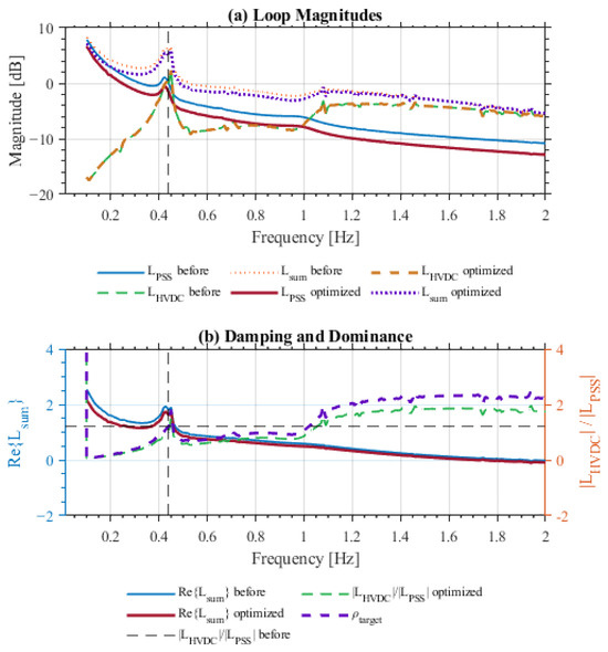
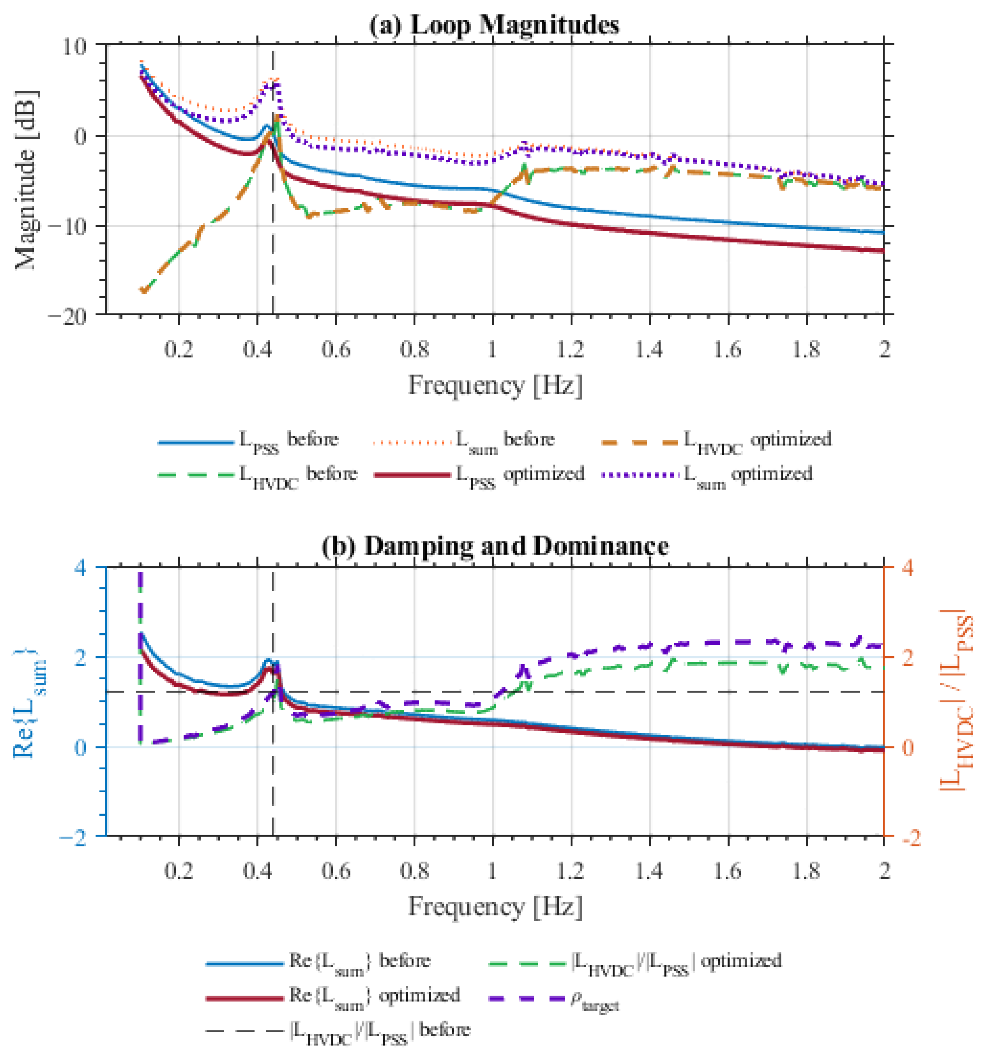
Figure 4 shows the results when the optimization enforces a high ratio target, i.e., strong weighting on equal participation between the AC and DC controllers. Under this constraint, both loops contribute almost equally to the overall damping torque. The HVDC loop magnitude increases, and the combined magnitude ratio remains above unity across most of the 0.1–1 Hz band.
Figure 4.
Open loop response with .
However, this balance comes at a cost. The real part of the total loop transfer function, decreases near the 0.46 Hz inter-area mode, indicating weaker positive torque and lower damping. Although authority sharing is achieved, phase alignment between the two channels deteriorates slightly, leading to partial cancelation of damping torques. This behavior illustrates that equal gain does not imply optimal damping when phase coherence is imperfect.
5.2. Case 2—Lower Ratio Target
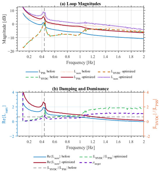
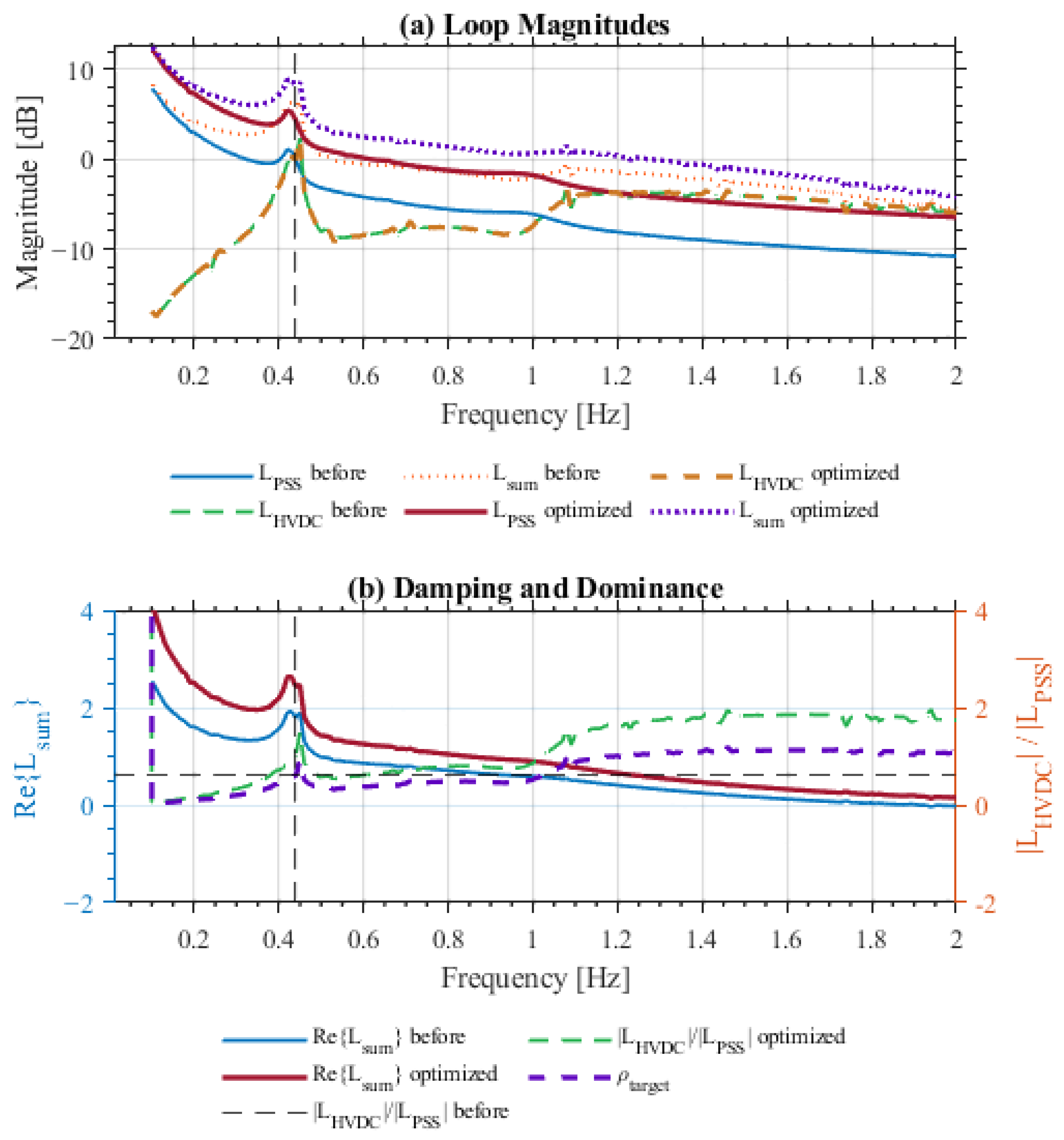
Figure 5 presents the results for a lower ratio target, where the optimization gives the PSS greater authority while the HVDC modulation acts as a supporting path. This configuration produces a higher and uniform positive across 0.1–1 Hz, confirming stronger net damping and better phase cooperation between the controllers. The magnitude responses of , and also exhibit smoother transitions, implying reduced loop interference. Comparing both cases shows that enforcing strict equality between PSS and HVDC torque contributions does not guarantee superior damping. Excessively high ratio targets amplify control interaction and may even reduce the total damping torque due to phase opposition. Moderate ratio targets, where the PSS dominates slightly, achieve a better trade-off between participation balance and effective damping.
Figure 5.
Open loop response with .
6. Conclusions
This paper has presented a measurement-based framework for coordinated tuning of power system stabilizers (PSSs) and HVDC Modulation Supplementary Damping Controllers (MSDC) in hybrid AC/DC systems. By embedding measured driving-point and transfer impedances directly into the control loops, the method captures the true small-signal environment experienced by both controllers, eliminating dependence on simplified analytical models. The proposed optimization algorithm simultaneously adjusts controller gains and phase-lead angles to maximize damping at the inter-area mode while enforcing three key coordination criteria: a defined HVDC-to-PSS dominance ratio, a consistent magnitude-crossing frequency, and a minimum damping margin across the 0.3–1.5 Hz electromechanical band.
Application of the framework to Kundur’s two-area benchmark demonstrated substantial improvements in damping uniformity and robustness. The coordinated design achieved stronger positive damping over the entire 0.01–2 Hz spectrum compared with conventional independent tuning, and successfully mitigated interaction effects that typically arise when the controllers are adjusted separately. The results confirmed that effective damping depends more on maintaining phase alignment between the PSS and HVDC modulation paths than on strictly matching their gain magnitudes. A moderate ratio target, typically between 0.6 and 0.7, provided the best trade-off between controller participation and phase coherence, yielding the uniform damping across the inter-area band.
The study further showed that the frequency-response-data-based (FRD) tuning approach ensures reproducibility and accuracy by characterizing the dynamic system response directly from small-signal measurements rather than through linearized models. This data-driven formulation mitigates the classical trade-off between enhancing low-frequency inter-area damping and degrading high-frequency local damping, which often limits conventional heuristic designs. Overall, the coordinated PSS–HVDC tuning framework offers a systematic and transparent means to achieve robust damping improvement in weakly interconnected or mixed-generation power systems.
Future work will extend the methodology to cover multiple HVDC infeeds and converter-interfaced renewable resources, and to validate the approach experimentally using real-time hardware-in-the-loop platforms, thereby confirming its applicability to large-scale practical systems.
Author Contributions
Conceptualization, R.V., J.v.C. and C.G.; methodology, R.V.; software, R.V.; validation, R.V., J.v.C. and C.G.; formal analysis, R.V.; investigation, R.V.; resources, J.v.C. and C.G.; data curation, R.V.; writing—original draft preparation, R.V.; writing—review and editing, R.V., J.v.C. and C.G.; visualization, R.V.; supervision, J.v.C. and C.G.; project administration, J.v.C.; funding acquisition, J.v.C. and C.G. All authors have read and agreed to the published version of the manuscript.
Funding
This research received no external funding.
Institutional Review Board Statement
Not applicable.
Informed Consent Statement
Not applicable.
Data Availability Statement
The data and MATLAB/ETAP scripts supporting the findings of this study are openly available in the GitHub repository: https://github.com/rvengesai17-cloud/engproc-140-00037.git (accessed on 7 April 2026).
Acknowledgments
During the preparation of this manuscript/study, the authors used ChatGPT, 5.2 for the purposes of proof reading. The authors have reviewed and edited the output and take full responsibility for the content of this publication.
Conflicts of Interest
The authors declare no conflicts of interest.
Abbreviations
The following abbreviations are used in this manuscript:
| AVR | Automatic Voltage Regulator |
| AC | Alternation Current |
| DC | Direct Current |
| HVDC | High Voltage Direct Current |
| PSS | Power System Stabilizer |
| FRD | Frequency-Response Data |
| ETAP | Power Systems Simulation Software |
| MATLAB | Simulation Software |
References
- De Mello, F.P.; Concordia, C. Concepts of synchronous machine stability as affected by excitation control. IEEE Trans. Power Appar. Syst. 1969, PAS-88, 316–329. [Google Scholar] [CrossRef] [Scilit]
- Kundur, P. Power System Stability and Control, 1st ed.; McGraw-Hill: New York, NY, USA, 1994. [Google Scholar]
- Larsen, E.V.; Piwko, J.J. Damping of power system oscillations by control of HVDC converters. IEEE Trans. Power Appar. Syst. 1981, PAS-100, 767–777. [Google Scholar]
- Larsen, E.V.; Piwko, J.J.; Long, W.F. Improving the dynamic performance of power systems by HVDC control. IEEE Trans. Power Appar. Syst. 1981, PAS-100, 481–489. [Google Scholar]
- Machowski, J.; Bialek, J.; Bumby, J. Power System Dynamics: Stability and Control, 3rd ed.; Wiley: Hoboken, NJ, USA, 2020. [Google Scholar]
- Kundur, P.; Paserba, J.; Ajjarapu, V.; Andersson, G.; Bose, A.; Canizares, C.; Hatziargyriou, N.; Hill, D.; Stankovic, A.; Taylor, C. Definition and classification of power system stability. IEEE Trans. Power Syst. 2004, 19, 1387–1401. [Google Scholar] [PubMed]
- Østbø, J.; Chow, J.H.; Germond, A.J.; Sanchez-Gasca, J.J. Wide-area power oscillation damping control in Nordic equivalent system. In Proceedings of the IEEE Power and Energy Society General Meeting, Denver, CO, USA, 6–10 June 2004. [Google Scholar]
- Gérin-Lajoie, L.; Lefebvre, D.; Racine, M.; Soulières, L.; Kamwa, I. Hydro-Québec experience with PSS tuning. In Proceedings of the IEEE Power Engineering Society Summer Meeting, Edmonton, AB, Canada, 18–22 July 1999. [Google Scholar]
- Wang, J.; Fu, C.; Zhang, Y. Design of WAMS-based multiple HVDC damping control system. IEEE Trans. Smart Grid 2011, 2, 363–374. [Google Scholar] [CrossRef] [Scilit]
- Elizondo, M.A.; Zhang, Y.; Pierre, B.J.; Huang, H. Inter-Area Oscillation Damping Control Using High-Voltage Direct Current (HVDC) and Multi-Terminal DC (MTDC) Systems; Pacific Northwest National Laboratory: Richland, WA, USA, 2018. [Google Scholar]
- Björk, J.; Uhlen, K.; Van Hertem, D. Analysis of coordinated HVDC control for power oscillation damping. In Proceedings of the IEEE eGrid Workshop, Aalborg, Denmark, 19–20 November 2018. [Google Scholar]
- Gustavsen, B.; Semlyen, A. Rational approximation of frequency domain responses by vector fitting. IEEE Trans. Power Deliv. 1999, 14, 1052–1061. [Google Scholar] [CrossRef] [Scilit]
- Huang, Y.; Vittal, V.; Heydt, G.T. Application of measurement-based impedance identification in power systems. IEEE Trans. Power Syst. 2011, 26, 2153–2160. [Google Scholar]
- Liu, Y.; Thorp, J.S.; Phadke, A.G. Impedance identification based on wide-area measurements. IEEE Trans. Power Syst. 2008, 23, 1197–1205. [Google Scholar]
- Hua, Y.; Liu, W. Generalized singular value decomposition method for harmonic retrieval. IEEE Trans. Signal Process. 1991, 39, 892–896. [Google Scholar] [CrossRef] [Scilit]
- Rogers, G. Power System Oscillations; Kluwer Academic: Boston, MA, USA, 2000. [Google Scholar]
- Chen, Y.; Zhang, Y. Coordinated control of power system stabilizers and HVDC damping controller using decentralized μ-synthesis. In Proceedings of the International Conference on Power System Technology (POWERCON), Chongqing, China, 22–26 October 2006. [Google Scholar]
- Vengesai, R.; van Coller, J.; Gomes, C. Emulation of LCC HVDC systems in ETAP for control interaction studies between PSS and HVDC modulation damping controllers. In Proceedings of the IEEE AFRICON 2025, Polokwane, Africa, 10–12 December 2025. [Google Scholar]
- Audet, C.; Dennis, J.E. Analysis of generalized pattern search methods. SIAM J. Optim. 2003, 13, 889–903. [Google Scholar] [CrossRef] [Scilit]
- Kolda, T.G.; Lewis, R.M.; Torczon, V. Optimization by direct search: New perspectives. SIAM Rev. 2003, 45, 385–482. [Google Scholar] [CrossRef] [Scilit]
- Torczon, V. On the convergence of pattern search algorithms. SIAM J. Optim. 1997, 7, 1–25. [Google Scholar] [CrossRef] [Scilit]
- Bertsekas, D.P. Nonlinear Programming; Athena Scientific: Belmont, MA, USA, 1999. [Google Scholar]
- Rockafellar, R.T.; Wets, R.J.-B. Variational Analysis; Springer: New York, NY, USA, 1998. [Google Scholar]
Disclaimer/Publisher’s Note: The statements, opinions and data contained in all publications are solely those of the individual author(s) and contributor(s) and not of MDPI and/or the editor(s). MDPI and/or the editor(s) disclaim responsibility for any injury to people or property resulting from any ideas, methods, instructions or products referred to in the content. |
© 2026 by the authors. Licensee MDPI, Basel, Switzerland. This article is an open access article distributed under the terms and conditions of the Creative Commons Attribution (CC BY) license.