


Abstract
We examined the performance of a novel early streamer emission air terminal (ESEAT), which is used as a lightning protection device. ESEAT was tested under a laboratory-simulated lightning strike scenario and compared with a classical air terminal (CAT). The results demonstrate that ESEAT is more effective at capturing artificial lightning in the laboratory setting than CAT. Data on failed lightning captures indicate that the failure rate of the ESEAT is approximately one-tenth that of CAT. These findings validate the effectiveness of the new ESEAT in a controlled laboratory environment.
1. Introduction
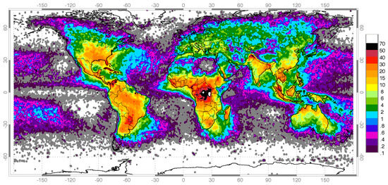
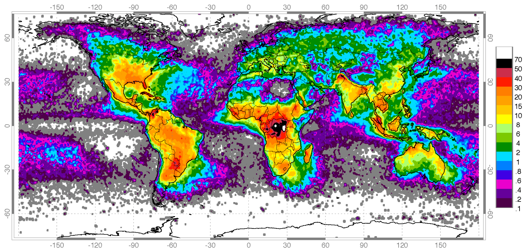
The National Aeronautics and Space Administration recorded the global lightning frequency map from January 1998 to February 2003, as shown in Figure 1 [1]. In areas suitable for human habitation, the average annual number of lightning strikes per square kilometer ranges from several to 70 occurrences. Wherever humans reside, there is a probability of lightning strikes. Lightning poses threats to life and causes property damage, necessitating the installation of protective devices to mitigate such disasters.
Figure 1.
Global lightning frequency.
The earliest lightning protection device invented was the traditional lightning rod, whose principle was first detailed by Franklin in 1749. It underwent improvements in the following years, was published in 1753, and was further refined into a reliable system around 1760 [2,3]. As a component of the lightning protection system, the classical air terminal (CAT) must be connected to the earth via a conductor, using the ground as the destination for releasing lightning strike energy to fulfill its protective function.
Technological evolution has enabled a significant increase in the vertical scale of modern urban structures. Consequently, the elevation of ground-based wireless communication equipment, such as signal transmission and reception devices, must also be increased to avoid communication dead zones and ensure high-performance radio signal transmission. This makes lightning protection critical. The installation of a lightning protection system must comply with lightning rod safety regulations to prevent failure. Otherwise, protection failures might occur [4]. Therefore, governments have established lightning rod installation standards. For example, in Taiwan, the Building Code stipulates that lightning protection equipment must be installed to protect buildings from lightning strikes, and buildings exceeding 20 m in height must be equipped with lightning protection devices that comply with legal regulations. Such measures were formulated to protect lives and property.
For outdoor lightning protection device installation, the placement of outdoor lightning rods is determined based on the size of the protection area. In Taiwan, if a building employs a traditional Franklin lightning rod for lightning protection, the cone formed by the tip of the rod and the perimeter of the protected ground area constitutes the protection range of the lightning rod. Half of the apex angle of this cone is defined as the protection angle, and it is required that the protection angle of the building must not exceed sixty degrees.
In this study, CAT and ESEAT were tested in a high-voltage laboratory for performance evaluation and comparison of lightning strike capture.
2. Lightning
Lightning strike generally refers to the occurrence of lightning in the Earth’s atmosphere reaching the ground. It commonly occurs at an altitude of several kilometers above sea level. The visible lightning strike phenomenon to the human eye is a bright discharge flash several kilometers long, appearing bright white due to the high temperature of the lightning. Typically, lightning originates from the base of clouds, about 1 to 2 km above sea level. When the flash reaches the ground, it is referred to as a lightning strike phenomenon.
The troposphere, which extends approximately 12 km (kilometer) above the Earth’s surface, is the layer of the atmosphere where most weather phenomena occur. As altitude increases, the temperature decreases by about 6.5 °C per km within this layer. At an altitude of four kilometers, temperatures drop below freezing, and at higher elevations, they can plummet to below −50 °C. Since the troposphere contains nearly all of the atmosphere’s water vapor, thunderstorms form under the right conditions of humidity, wind speed, air pressure, and temperature. The formation process is simplified as follows.
- Rising water vapor encounters low temperatures, forming small ice crystals. Collisions between these crystals result in charge separation, with positively charged ice crystals being carried upward by updrafts to the top of the thundercloud, reaching altitudes of nearly 10 km.
- These small ice crystals combine to form heavier hailstones, which either remain suspended or fall within the storm’s updrafts. At altitudes of 6–8 km, negatively charged hailstones accumulate, creating the charge distribution within the thundercloud.
- Before a lightning strike occurs, the base of the cloud accumulates sufficient negative charge to produce a corona discharge. Under the right conditions, this discharge initiates a downward leader toward the ground, marking the beginning of a lightning event.
- As the downward leader approaches the ground, the strong electric field induces an upward leader from the surface. When these two leaders connect, a lightning strike occurs. Details on the mechanisms of downward and upward leaders are presented in Ref. [5].
When lightning approaches the ground, the traditional CAT lightning rod provides an upward leader to capture the downward leader, thereby protecting ground structures from lightning strikes. CAT is a lightning strike capture device. Compared with CAT, the newly designed early streamer emission air terminal (ESEAT) captures the downward leader at a higher altitude [6,7], with this advance time being approximately tens of microseconds. ESEAT has a larger protection range and better lightning strike prevention performance.
3. Materials and Methods
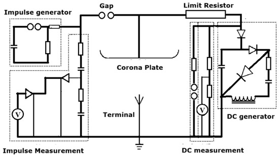
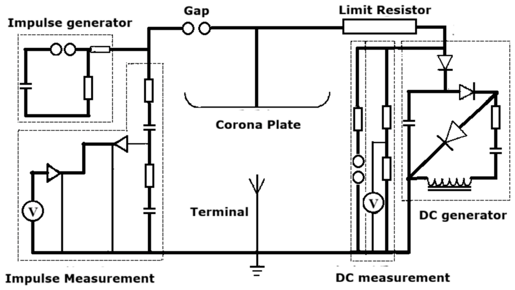
The lightning rod verification and lightning strike simulation system is shown in Figure 2.
Figure 2.
Lightning strike simulation system.
Based on its functions, it comprises the following three parts: (1) lightning rod test area; (2) high-voltage generator; (3) voltage signal measurement instrument. The middle part of the figure shows the aluminum alloy-made thundercloud plate and the grounding plane, which together form the lightning rod test area, where the lightning rod to be tested is placed on the grounding plane. The impact body part in the figure is the high-voltage generator, which generates a pulse voltage. The impact measurement part in the figure is the voltage signal measurement instrument, which records the voltage signal changes over time when the lightning rod receives the pulse voltage.
This high-voltage system generates high-voltage outputs for two subsystems: (1) the DC bias subsystem produces high voltage to simulate the corona phenomenon generated by natural lightning strikes, and (2) the pulsed voltage subsystem generates high voltage to simulate the natural triggering of lightning strikes. Since natural lightning clouds exhibit a negatively charged phenomenon, both the DC bias and pulsed voltages are negative high voltages.
The steps for generating voltage to simulate lightning strike phenomena are as follows. The DC main body generates a fixed bias voltage, which is sent to the thundercloud plate through a current-limiting resistor. An electric field is created between the thundercloud plate and the ground, ionizing nearby air molecules into charged molecules. The charging and discharging process forms a corona discharge phenomenon. Then, the impulse main body generates a ten times higher voltage pulse, which is sent to the thundercloud plate via an isolated discharge gap to trigger the simulated lightning strike. The impulse measurement subsystem monitors the high-voltage pulse. Finally, the DC measurement subsystem monitors and records the voltage signals between the thundercloud plate and the ground. The test conditions of the simulation system are listed in Table 1.
Table 1.
Simulation system test conditions.
The high-voltage system’s aluminum alloy-made thundercloud plate serves as a conductive carrier for generating pulsed negative high voltage. When a high-voltage pulse enters the thundercloud plate, a strong electric field is formed between the thundercloud plate and the grounded plate. The measured voltage on the thundercloud plate varies over time, where a negative high voltage is detected. If no lightning capture device is installed in this area, the voltage remains elevated. When a lightning capture device is present and captures a simulated lightning signal, the level of DC returns to that of the ground voltage due to discharge. Installing a lightning capture device between the thundercloud plate and the ground enables charge release through conduction, which is equivalent to installing a lightning rod in nature to attract lightning and protect nearby objects or personnel.
The testing method adopted in this study complies with the French standard Norme Française C 15 17-102 (09/2011) for early streamer emission lightning protection systems. The CAT was fixed at the grounding terminal for testing and then replaced by ESEAT to conduct the same test.
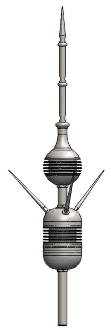
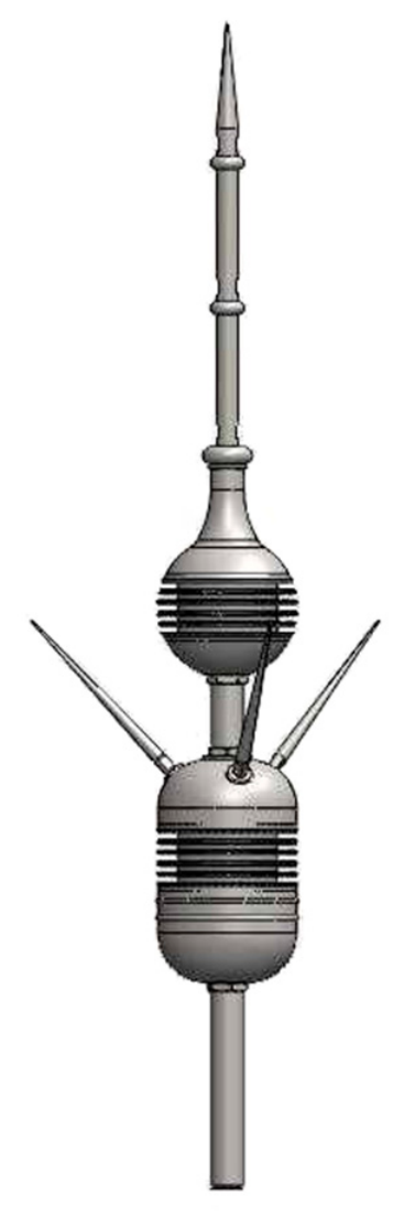
ESEAT used in the experiment is made of stainless steel SUS-304, with a height of 170 cm, and uses an insulating material (UV-resistant plastic) as a partition to provide an early streamer emission effect [3]. In this study, CAT was made of a pure copper rod with a diameter of 1 in. and a length of 170 cm (Figure 3).
Figure 3.
ESEAT for tests [3].
The lightning strike capture test involved simulating lightning with high-voltage pulses, where the lightning rod was set to receive a total of 100 lightning strikes. The number of successful and failed captures was recorded, with a time interval of 2 min between each consecutive test.
4. Results and Discussions
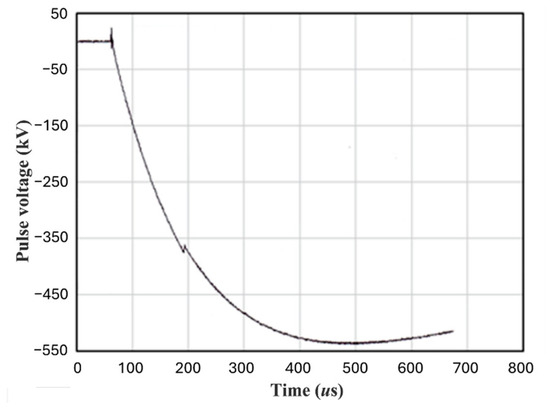
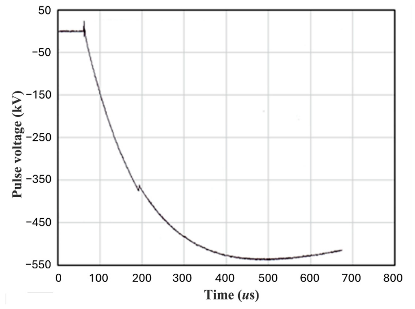
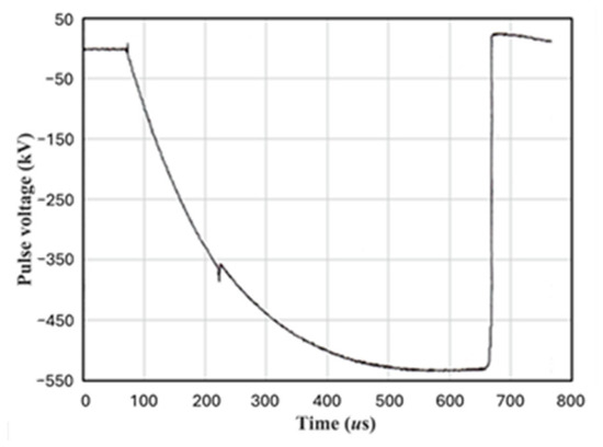
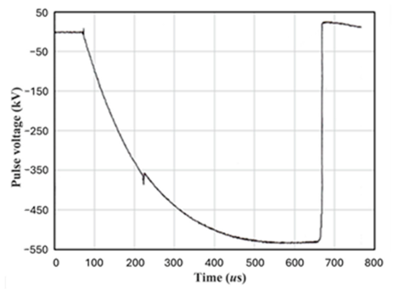
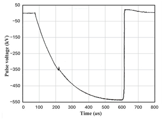
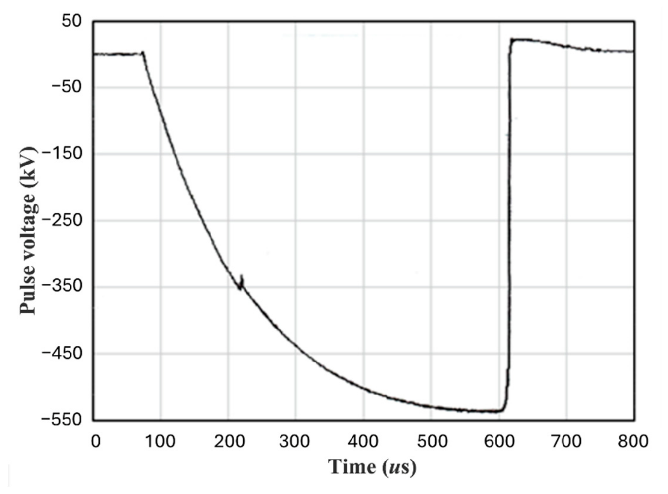
Figure 4 shows the test without a lightning strike capture device installed, recording the voltage waveform of the lightning cloud plate. The recording duration is 800 μs. Since no lightning strike capture device is installed, the voltage on the lightning cloud plate remains high, and the discharge voltage gradually recovers slowly.
Figure 4.
Simulated lightning strike generated a high-voltage pulse.
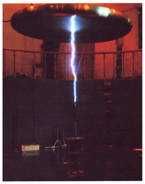
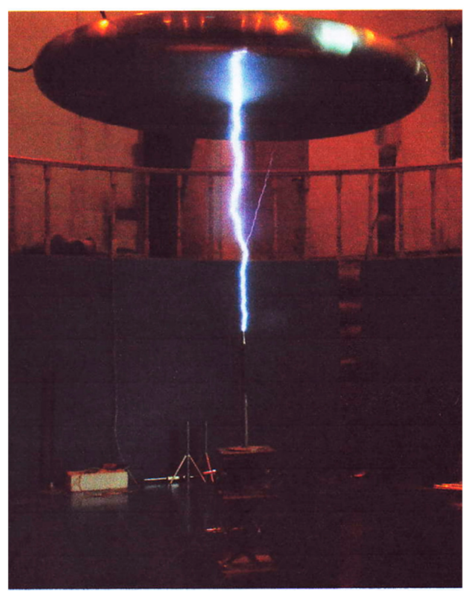
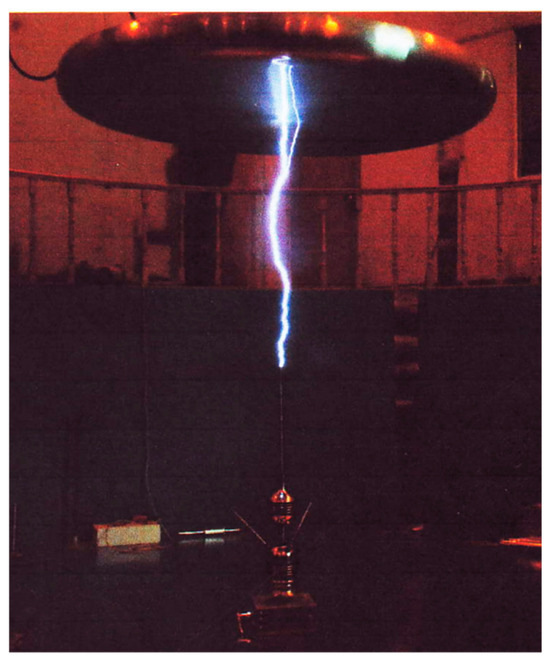
Figure 5 shows the installation of the CAT as a lightning protection device at the grounding end. The voltage waveform recorded on the lightning simulation plate rapidly returns to 0 (grounded) around 670 μs, indicating that the simulated lightning strike has been captured by CAT, and the high voltage on the lightning simulation plate has been eliminated. Figure 6 records the successful reception of the simulated lightning strike by CAT.
Figure 5.
Measurement voltage waveform of the pulse captured by CAT during a simulated lightning strike.
Figure 6.
CAT successfully captures simulated lightning strikes.
Figure 7 shows the voltage waveform recording from the lightning plate when the ESEAT surge protection device was installed at the grounding end. At 620 μs, the voltage rapidly dropped to 0, indicating that the simulated lightning strike was successfully intercepted by the ESEAT, and the high voltage from the lightning plate was dissipated. Figure 8 shows the successful reception of the simulated lightning strike by the ESEAT.
Figure 7.
Measured voltage waveform of simulated lightning strike pulses captured by ESEAT.
Figure 8.
ESEAT successfully captured the simulated lightning strike.
The discharge curves of simulated lightning received by traditional lightning rods and ESE lightning rods under experimental conditions were observed. Figure 5 shows that the charge on the thundercloud plate is completely released in a very short time, resulting in a rapid voltage recovery. The data shows that the CAT discharge time is 660 microseconds. On the other hand, Figure 7 shows that under the same test conditions, the ESE starts the discharge process at an earlier time of 620 μs. The experimental results show that the ESE can receive artificial lightning earlier and achieve a better lightning attraction effect.
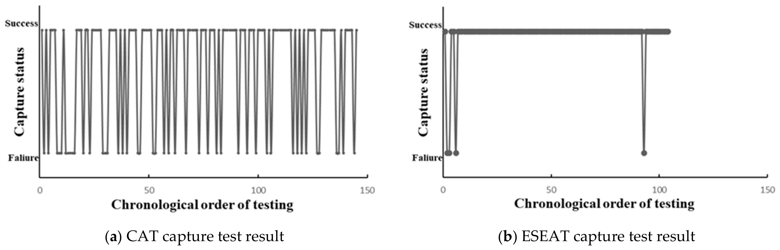
For the effectiveness verification of the lightning capture device, it was installed at the grounding terminal and multiple lightning strike tests were conducted. The process was repeated until the device successfully captured 100 simulated lightning strikes, at which point the testing was stopped.
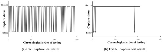
Figure 9a shows the test results of the CAT lightning strike capture, successfully capturing 100 simulated lightning strikes out of a total of 145 generated. Among them, 45 simulated strikes were received. The failure rate of the lightning capture device is defined as the ratio of uncaptured simulated strikes to successfully captured simulated strikes, with CAT’s failure rate being 0.45 (45/100). As shown in Figure 9b, ESEAT successfully recorded 100 simulated lightning strikes out of a total of 104 generated, resulting in a failure rate of 0.04 (4/100).
Figure 9.
(a) CAT successfully captured 100 simulated lightning strike test results; (b) ESEAT successfully captured 100 simulated lightning strike test results.
5. Conclusions
Using a high-voltage pulse generator, we produced short-pulse voltages, simulating the natural lightning phenomenon in a laboratory setting, to evaluate the performance of CAT and ESEAT. The testing methodology follows the NFC 17-102 standard issued in September 2011. Under laboratory conditions, we studied and compared the discharge time difference and flashover success rate of the two types of lightning rods. From the experimental results, the initial discharge time of the ESE lightning rod is 40 μs shorter than that of the CAT, indicating better protection capacity to capture lightning from the environment. Further, the calculated failure rate of our ESEAT is significantly lower than that of CAT, and the results of our study clearly demonstrate the superiority of ESEAT. The lightning strike failure rate of ESEAT is only 1/10 that of CAT. Comparing both sets of test data, we verify that the lightning protection performance of the ESEAT device is superior to that of the CAT device. However, in the real natural world, there are uncertainties such as temperature, humidity, air pressure, and different terrain and landforms outdoors, which cannot be simulated in the laboratory setup. This study be directly generalized to open-air situations. From the quick discharge time and low failure rate of the ESEAT, we recommend that early streamer emission (ESE) lightning rods be prioritized over conventional ones when lightning rods are to be installed.
Author Contributions
Conceptualization, Y.-H.A.C. and K.-J.L.; methodology, Y.-H.A.C. and Y.-C.M.L.; software, Y.-H.A.C.; validation, Y.-H.A.C. and K.-J.L.; writing—review and editing, Y.-H.A.C. and K.-J.L.; All authors have read and agreed to the published version of the manuscript.
Funding
This research received no external funding.
Institutional Review Board Statement
Not applicable.
Informed Consent Statement
Not applicable.
Data Availability Statement
Data are contained within the article.
Conflicts of Interest
The authors declare no conflict of interest.
Abbreviations
The following abbreviations are used in this manuscript:
| CAT | Conventional Air Terminal |
| ESEAT | Early Streamer Emission Air Terminal |
References
- Koko Agustinus, C.H.; Iskandar, I. Lightning protection according NFC17-102. Int. J. Sci. Eng. Res. 2019, 10, 1312–1317. [Google Scholar]
- Jernegan, M.W. Jernegan Benjamin Franklin’s “Electrical Kite” and Lightning Rod. N. Engl. Q. 1928, 1, 180–196. [Google Scholar] [CrossRef] [Scilit]
- Chen, Y.H.A.; Lin, K.J.; Li, Y.C.M. Assessment to effectiveness of the new early streamer emission lightning protection system. Int. J. Smart Sens. Intell. Syst. 2017, 10, 1–26. [Google Scholar] [CrossRef] [Scilit]
- Hong Kong News Network: Hong Kong Unit Struck by Lightning, Female Homeowner Recounts Harrowing Moment [Online News]. 2023. Available online: http://www.hkcna.hk/docDetail.jsp?id=100374467&channel=2803 (accessed on 16 April 2026).
- Dwyer, J.R.; Uman, M.A. The physics of lightning. Phys. Rep. 2014, 534, 147–241. [Google Scholar] [CrossRef] [Scilit]
- Hartono, Z.A.; Robiah, I. Conventional and Un-conventional Lightning Air Terminals: An Overview. In Proceedings of the Forum on Lightning Protection, Petaling Jaya, Malaysia, 8 January 2004; pp. 1–39. [Google Scholar]
- Van Brunt, R.J.; Nelson, T.L.; Stricklett, K.L. Early streamer emission lightning protection systems: An overview. IEEE Electr. Insul. Mag. 2000, 16, 5–24. [Google Scholar] [CrossRef] [Scilit]


Disclaimer/Publisher’s Note: The statements, opinions and data contained in all publications are solely those of the individual author(s) and contributor(s) and not of MDPI and/or the editor(s). MDPI and/or the editor(s) disclaim responsibility for any injury to people or property resulting from any ideas, methods, instructions or products referred to in the content. |
© 2026 by the authors. Licensee MDPI, Basel, Switzerland. This article is an open access article distributed under the terms and conditions of the Creative Commons Attribution (CC BY) license.