


Abstract
The structural design of aeronautical composite components requires numerical models which capture multilayer behaviour while keeping computational costs manageable. High-fidelity three-dimensional (3D) finite element models are often too expensive for systematic optimisation, whereas classical 1D and 2D formulations rely on simplifying assumptions. This work investigates the Carrera Unified Formulation (CUF) as a cost-effective composite simulation tool, using Equivalent Single-Layer (ESL) and Layer-Wise (LW) beam models whose hierarchical cross-sectional expansions approximate 2D/3D behaviour within a one-dimensional framework. A representative composite stiffened panel is analysed to compare 3D solid, 2D shell, CUF-ESL, and CUF-LW models in terms of static response and computational cost. High-order CUF-ESL models reproduce 3D strain fields with 2–7% error while reducing analysis time by over 89%. The CUF–FEM framework is then integrated into a gradient-based optimisation scheme with Automatic Differentiation, adjoint sensitivities, and Kreisselmeier–Steinhauser constraint aggregation. Panel optimisation achieves a 64% mass reduction in six iterations with CUF-ESL, compared with 56% in 18 iterations for the 2D shell model. The results prove that CUF-ESL beam models are a computationally cost-effective tool for preliminary sizing of composite structures.
1. Introduction
The structural design of aeronautical composite components is becoming increasingly reliant on numerical models and optimisation tools capable of exploring large design spaces at affordable computational cost.
High-fidelity three-dimensional (3D) Finite Element (FE) models offer accurate mechanical response predictions, but their large number of degrees of freedom (DOFs) makes them impractical for iterative optimisation routines, requiring hundreds of structural evaluations. Conversely, reduced-order one-dimensional (1D) or two-dimensional (2D) formulations enable faster analyses but rely on simplifying kinematic assumptions which may compromise accuracy in regions with significant through-thickness deformation or strong stiffness variations. Selecting an appropriate modelling strategy is therefore central to the preliminary sizing of composite-stiffened panels, where skins, webs, and flanges interact through highly heterogeneous laminates. Classical beam theories, from Euler–Bernoulli [1] to Timoshenko [2], provide the basis for modelling slender structures by predicting bending, torsion, and shear deformations. Modern FE formulations have extended structural simulation implementing shells and solids [3], which remain the industrial standard for global analysis of aircraft structures. However, computational cost often limits their use in simulation-driven design and optimisation. To overcome these limitations, several refined and higher-order theories have been proposed for composite beams, plates, and shells, with particular emphasis on shear effects, buckling, and vibration response [4]. Within this context, the Carrera Unified Formulation (CUF) offers a hierarchical and systematic framework for the modelling of multilayered beams, plates, and shells [5,6]. CUF implements variable-order cross-sectional expansions which allow us to enrich the kinematics as needed, recovering classical beam theories as special cases and enabling consistent convergence studies. Equivalent Single-Layer (ESL) models based on Taylor expansions (TEs) approximate the cross-section as a homogenised continuum, while Layer-Wise (LW) models based on Lagrange expansions (LE) resolve each lamina explicitly. Through this unified approach, CUF can approximate 2D or 3D mechanical responses with significantly fewer DOFs, making it attractive for optimisation frameworks where accuracy and computational efficiency must coexist. Recent applications to wing-type structures [7] confirm the suitability of CUF for aerospace airframe analyses. Recent developments in gradient-based optimisation and its application as design tool of large structure [7] have further increased the benefits of reduced-order models. Techniques such as the Kreisselmeier–Steinhauser (KS) [8,9] constraint aggregation allow large sets of local strain or stress constraints to be represented by smooth scalar functions, while Sequential Least SQuares Programming (SLSQP) [10] provides robust convergence for problems with many design variables. Accurate sensitivity calculation is essential in this context, and reverse-mode Automatic Differentiation (AD) [11], coupled with adjoint equations [12], enables exact gradients at a cost nearly independent of the number of design variables.
This work investigates the integration of CUF beam models within an adjoint-based optimisation framework for the mass minimisation of a composite stiffened panel representative of airframe structures. Different models, ranging from 3D solids to 2D shells and CUF beam formulations with increasing expansion orders, are systematically assessed to characterise the trade-offs between fidelity and computational performance. The objective is to determine whether CUF models can replace 2D shell formulations in early-stage design, providing sufficiently accurate mechanical responses for gradient-based optimisation at a fraction of the computational cost. The rest of the paper is structured as follows. Section 2 introduces the CUF theoretical framework, the modelling hierarchy, and the stiffened panel benchmark. Section 3 presents a detailed comparison of static responses and discusses the convergence properties of the different model families. Section 4 reports the optimisation results based on adjoint sensitivities and KS-aggregated strain constraints. Finally, the last section summarises the main findings and outlines directions for future research, including extensions to multiple load cases, buckling, and multi-fidelity optimisation strategies.
2. Methodology
2.1. Theoretical Background
The theoretical framework underpinning the suggested models couples FEM with CUF. CUF introduces a hierarchical expansion of the cross-section, allowing higher-order deformation modes to be characterised, overcoming beam theory limitation and enabling convergence studies by varying the expansion order [7]. The same modelling strategy can therefore be adapted to problems of different complexities. In this approach, the displacement field of a beam-like structure (1) is written as a product of longitudinal shape functions () and cross-sectional expansion functions () multiplied by a vector of unknown degrees of freedom ().
Two types of expansion functions are used. Taylor Expansions (TEs) provide an Equivalent Single-Layer (ESL) description of the cross-section, which is treated as a single equivalent continuum, and cross-sectional displacement fields are represented by a Taylor series, homogenising the individual layers of the laminate. TEn denotes a Taylor expansion of order n in the cross-section within the CUF notation, so that TE1 and TE2, correspond respectively to first- and second-order polynomial approximations of the cross-sectional displacement field within the ESL framework. TE1 is equivalent to a Timoshenko-like beam theory, while larger expansion order allows the representation of increasingly complex cross-sectional deformation modes. In contrast, Lagrange Expansions (LEs) adopt a Layer-Wise (LW) description, using Lagrange functions within elements discretising the cross-section. For instance, a four-node quadrilateral element (L4) leads to a bilinear (first-order) polynomial interpolation, whereas a nine-node quadrilateral element (L9) yields a biquadratic (second-order) representation. LE modelling is computationally more expensive than TE, but yields results closely approaching those of full 3D formulations, especially for complex geometries and pronounced through-thickness effects. The governing equations are obtained from the principle of virtual work, leading to a weak form where the global stiffness matrix is assembled by integrating contributions from both the longitudinal shape functions and the cross-sectional expansions. The hierarchical nature of CUF permits adaptive refinement either by increasing the order of the cross-sectional expansion or refining the mesh along the beam axis, ensuring accurate representation of bending, torsion and cross-sectional deformation while retaining beam element computational efficiency.
Within the optimisation framework, the CUF–FEM theory enables the structural analyses used to evaluate design responses. Gradients are efficiently computed via a hybrid reverse approach leveraging Automatic Differentiation (AD) and adjoint equation solution.
2.2. Test Case Description
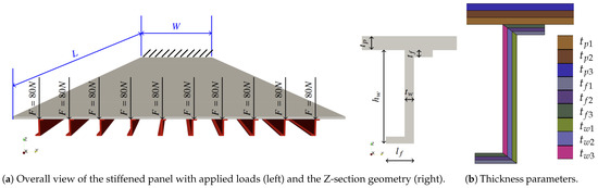
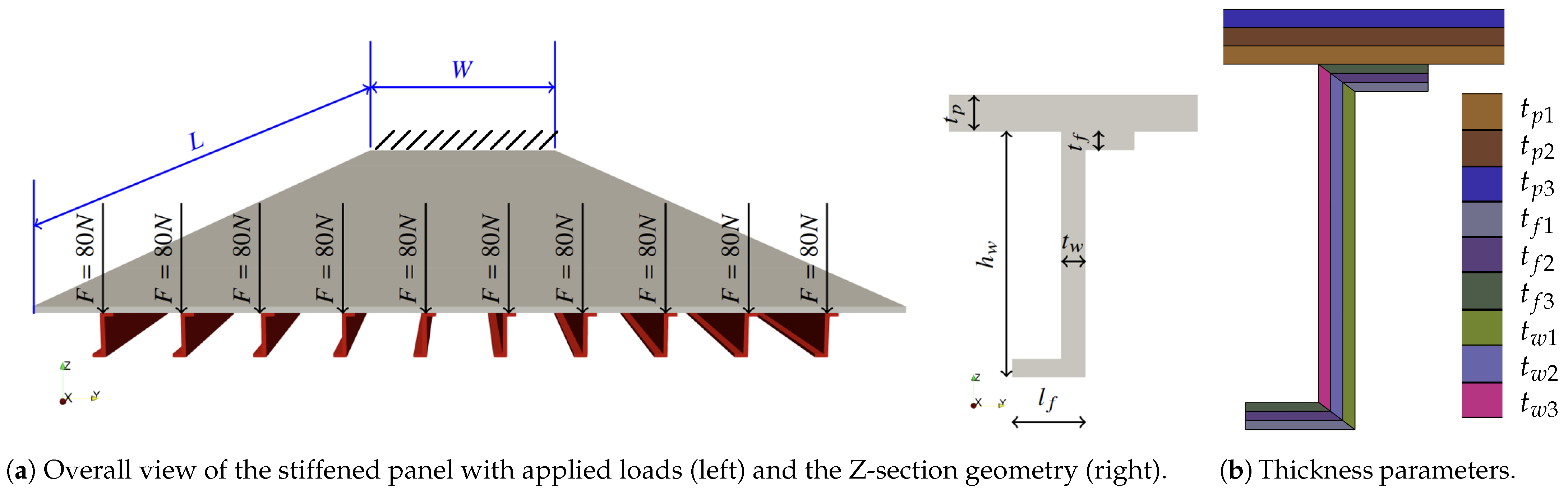
The benchmark structure consists of a composite stiffened panel with Z-shaped stringers, representative of a typical airframe component [7] (Figure 1a). The panel has an overall length of L = 1620 and a width of W = 390 . Ten identical Z-stringers are evenly distributed across the width. Each stringer comprises a web and two flanges, while the upper skin forms the panel surface. Figure 1 shows a schematic of the panel, its cross-section and the component stacking sequence.
Figure 1.
Geometric configuration and composite lay-up of the stiffened panel. The colours correspond to the ply-thickness parameters – (panel), – (flange), and – (web).
Structural components are made of unidirectional laminated composite material with stacking sequence . Table 1 summarises nominal ply thicknesses and fibre orientations for the three subcomponents: panel skin and stringer flange and web. Each component consists of three plies, reaching a total laminate thickness of 3 , , and 2 , respectively , and (Figure 1a).
Table 1.
Ply stacking sequence and thickness distribution for the composite-stiffened panel.
Figure 1b displays the panel cross-section, highlighting the laminate stacking sequences of different panel regions.
The panel is clamped on one end and free along the opposite side. Ten concentrated loads of 80 are applied above the stringer web centrelines in the longitudinal direction (Figure 1a). Table 2 lists the unidirectional CFRP lamina properties using conventional notation.
Table 2.
Material properties of the unidirectional composite lamina: density , Young’s moduli and , Poisson’s ratio , and shear modulus .
The stiffened panel shows an initial laminate mass of , which is used as the reference configuration for the optimisation study.
2.3. Optimisation Problem Formulation
The optimisation design variables (DVs) are the nine individual ply thicknesses constituting the skin (), the stringer web () and the stringer flange (). The stacking sequence is fixed, whereas the optimiser is free to vary each ply thickness independently. The optimisation aims at minimising the total structural mass.
where is the DV vector and is the mass of the laminate computed from the ply volumes. Two classes of constraints are imposed:
- Aggregated strength constraint in terms of strain. The constraint is formulated using the laminate strain components evaluated at the FE integration points. The maximum admissible absolute principal strain is set to . The individual laminate strain components are aggregated using the KS function, Equation (3), with smoothing parameter , resulting in a single differentiable constraint. The KS function approximates the envelope of the constraints set while guaranteeing feasibility. Larger values provide a closer approximation to the true shape at the cost of more iterations for convergence [9].
- Bounds on design variable. To ensure structural integrity and manufacturability, each ply thickness design variable is bounded. Table 3 lists the nine thickness limits implemented in the optimisation while the nominal initial ply thicknesses are reported in Table 1. The thickness values in Table 1 are continuous design values. They should be interpreted as ideal target thicknesses, which would need to be converted into a manufacturable stacking sequence in a subsequent design step.
Table 3.
Lower and upper bounds for the nine ply-thickness DVs.
The bounds in Table 3 are chosen consistently with the initial total laminate thicknesses reported in Table 1, while allowing the optimiser to redistribute material across individual plies. The optimisation problem is solved using a SLSQP algorithm. The sensitivities of the design responses (objective function and constraints) are computed through reverse-mode AD, ensuring exact and efficient gradient calculation for all DVs. At each optimisation iteration, a structural analysis is performed to evaluate the mass, and an adjoint analysis is carried out to compute the corresponding sensitivities. The optimisation is initialised using the ply thicknesses reported in Table 1. Convergence is declared when the internal first-order optimality measure of the SLSQP algorithm falls below , and all DVs are internally scaled by the optimiser to improve numerical conditioning. The 2D and 3D models were solved in Altair OptiStruct 2024.1 (Altair Engineering Inc., Troy, MI, USA). CUF models were implemented in the in-house C++ code AUGUSTO++ (UC3M, Leganés, Spain). All simulations were executed on a computational platform with an i9–14900HX CPU (24 cores) and 32 GB DDR5 RAM.
3. Results and Discussion
3.1. Static Analyses and Model Convergence
A comprehensive linear static analysis of the stiffened composite panel is carried out using four model fidelities: a high-fidelity 3D solid model and a 2D shell formulation developed on the commercial software OptiStruct plus two CUF beam models based on LE and TE. The objective is to assess the CUF beam models’ trade-off between accuracy and computational cost against the 3D and 2D reference models.
A convergence study is performed by progressively refining or enriching each model family. For the 3D solid, 2D shell, and CUF–LE beam models, the mesh is gradually refined by increasing the number of solid, shell, and beam elements, respectively. For the CUF–TE model, an initial 1D mesh convergence study is first carried out to identify a sufficiently refined beam discretisation, and, once this is fixed, the order of the TE expansion on the cross-section is increased. The 3D solid model uses eight-node hexahedral elements; the in-plane mesh was refined from 6 mm to 1 mm, with the converged configuration producing DOF. The 2D shell model employs four-node layered shells with mesh sizes from 6 mm to 0.5 mm; a 3 mm mesh was selected, yielding DOF. The CUF beam models share the same 1D axial mesh, refined from 27 to 54, 81, and 108 elements; 108 elements were selected for the converged configurations. CUF–LE adopts a cross-sectional expansion using L4, whereas CUF–TE employs expansions from order TE1 to TE6, with TE3 selected for the optimisation study.
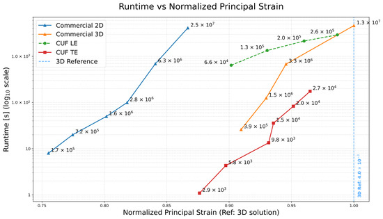
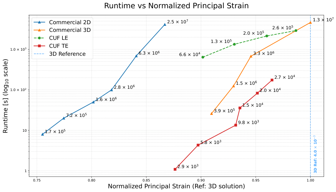
Figure 2 summarises the convergence study outcome by relating runtime to the calculated maximum principal strain value normalised by the converged 3D solid solution one. A logarithmic scale is used on the vertical axis to capture the three-order-of-magnitude variation in computational cost across the models. Each marker corresponds to a refined or enriched configuration: increasing mesh density for the 3D, 2D, and CUF–LE models, and the Taylor expansion order for the CUF–TE formulations. DOF labels are displayed next to each marker to quantify the FE system size.
Figure 2.
Normalised maximum principal strain for all models; the blue dashed line represents the 3D reference solution.
The commercial 3D model is capable of reaching the maximum strain value, although at a rapidly escalating computational time. The 2D shell results considerably more efficient, yet its strain predictions saturate early without approaching the benchmark due to reduced through-thickness kinematics. The CUF–LE model offers an improved accuracy–cost balance, outperforming the 2D shell accuracy for comparable runtimes, though its predicted strain plateaus below the 3D reference. In contrast, the CUF–TE formulation provides the most advantageous compromise: once an adequate 1D mesh is selected, enriching the cross-section kinematics allows us to approximate the 3D benchmark result with runtimes that are one to two orders of magnitude lower. In particular, CUF–TE3 calculates the strain within ≤7% error from the reference 3D value, while reducing the DOF count by three orders of magnitude and runtime by .
Therefore, CUF–TE3 (with DOF) is selected as the model for the subsequent optimisation study and compared against the size optimisation performed on the 2D shell configuration (with DOF).
3.2. Optimisation Results
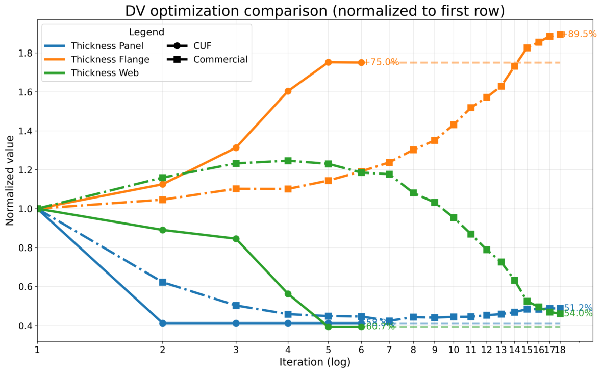
Two sizing optimisations are performed with identical problem settings (Section 2.3): one using the industrial 2D shell model and the other using the CUF–TE3 formulation. Table 4 summarises the optimisation campaign outcomes. Both models converge qualitatively to the same material distribution: a strong thickness reduction on the skin and stringer web and a marked thickening of the stringer flanges, consistent with the bending-dominated stiffened panel response. The CUF–TE3 model attains a larger mass reduction ( versus ) with only six iterations and 564 s of wall time, whereas the 2D shell requires 18 iterations and 2912 s.
Table 4.
Optimisation outcomes. Mass variations are relative to the initial kg.
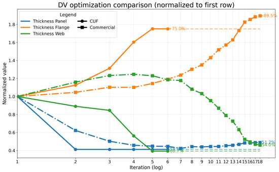
Figure 3 shows the normalised evolution of the three thickness groups (panel, web, flange) for both optimisation models. Both analyses progressively remove material from the skin panel and stringer web while increasing the flange thickness. The CUF–TE3 reaches its optimum mass in fewer iterations and with smoother convergence. The shell model follows the same trend but features a less aggressive thickness reduction of panel and web and a stronger over-thickening of the flanges, consistent with its tendency to underpredict maximum strains (Figure 2).
Figure 3.
Normalised evolution of the DV groups (panel, flange, web) for CUF–TE3 and 2D shell.
Overall, both optimisations converge to a physically meaningful architecture characterised by thin panel and web and thickened flanges. CUF–TE3 achieves this layout with substantially fewer degrees of freedom, fewer iterations, and about five times lower runtime, confirming its suitability as an analysis tool within gradient-based sizing workflows.
4. Conclusions
This work shows that CUF, coupled with an adjoint-based optimisation framework, provides a practical balance between fidelity and computational cost for sizing aircraft composite-stiffened panels. CUF beams reproduce stiffened panel static responses close to the 3D solid reference while cutting degrees of freedom and computational time by over two orders of magnitude. Within optimisation frameworks, both CUF–TE3 and the commercial 2D shell baseline converge to the same physically consistent architecture, yet CUF–TE3 achieves a 64% mass reduction in six iterations and ∼564 s versus 56% in 18 iterations and ∼2912 s of the shell model, underscoring the value of accurate through-thickness kinematics and efficient adjoint sensitivities with AD. These results support a design workflow in which CUF beam models are used as the default analysis tool for early-stage sizing, with shells or solids reserved for local checks and detailed stress analysis. The study is limited to linear elastic static analyses with fixed lay-up and a single loading scenario. Future work will extend the framework to buckling and vibration constraints, multiple load cases, probabilistic or robust optimisation, and adaptive CUF order within multi-fidelity strategies, further shortening design cycles while preserving the accuracy required for certifiable and lightweight composite structures.
Author Contributions
Conceptualization, D.C. and A.C.; Methodology, D.C.; Software, D.C.; Validation, D.C.; Formal analysis, D.C.; Investigation, D.C.; Resources, R.C.; Data curation, D.C.; Writing—original draft preparation, D.C.; Writing—review and editing, A.C.; Visualization, D.C.; Supervision, R.C. and A.C.; Project administration, A.C.; Funding acquisition, A.C. All authors have read and agreed to the published version of the manuscript.
Funding
This research was funded by the Spanish Agencia Estatal de Investigación (AEI) under the “Programa Transmisiones”, project TIFON (Tecnologías Inteligentes para la Fabricación, el Diseño y las Operaciones en entornos Industriales), grant number PLEC2023-010251.
Institutional Review Board Statement
Not applicable.
Informed Consent Statement
Not applicable.
Data Availability Statement
The data and numerical models supporting the findings of this study are available from the corresponding author upon reasonable request. No publicly archived datasets were generated.
Acknowledgments
This work was conducted within the project TIFON (Tecnologías Inteligentes para la Fabricación, el Diseño y las Operaciones en entornos Industriales), coordinated by the Universidad Politécnica de Madrid (UPM).
Conflicts of Interest
The authors declare no conflicts of interest. The funders had no role in the design of the study; in the collection, analyses, or interpretation of data; in the writing of the manuscript; or in the decision to publish the results.
References
- Euler, L. Methodus Inveniendi Lineas Curvas Maximi Minimive Proprietate Gaudentes; Bousquet: Lausanne, Switzerland, 1744. [Google Scholar]
- Timoshenko, S.P. On the Correction for Shear of the Differential Equation for Transverse Vibrations of Prismatic Bars. Philos. Mag. 1921, 41, 744–746. [Google Scholar] [CrossRef] [Scilit]
- Zienkiewicz, O.C.; Taylor, R.L. The Finite Element Method, Vol. 2: Solid Mechanics, 5th ed.; Butterworth-Heinemann: Oxford, UK, 2000. [Google Scholar]
- Kapania, R.K.; Raciti, S. Recent Advances in Analysis of Laminated Beams and Plates, Part I: Shear Effects and Buckling. AIAA J. 1989, 27, 923–934. [Google Scholar] [CrossRef] [Scilit]
- Carrera, E. Theories and Finite Elements for Multilayered Plates and Shells: A Unified Compact Formulation with Numerical Assessment and Benchmarking. Arch. Comput. Methods Eng. 2003, 10, 215–296. [Google Scholar] [CrossRef] [Scilit]
- Carrera, E.; Giunta, G. Refined Beam Theories Based on a Unified Formulation. Int. J. Appl. Mech. 2010, 2, 117–143. [Google Scholar] [CrossRef] [Scilit]
- Cardone, D.; Cavallaro, R.; Cini, A.; Petrolo, M.; Zappino, E. Application of CUF for the Structural Optimization of Wings. In Proceedings of the AIAA SciTech 2025 Forum, Orlando, FL, USA, 6–10 January 2025. AIAA Paper 2025-1745. [Google Scholar] [CrossRef] [Scilit]
- Kreisselmeier, G.; Steinhauser, R. Systematic Control Design by Optimizing a Vector Performance Index. IFAC Proc. Vol. 1979, 12, 113–117. [Google Scholar] [CrossRef] [Scilit]
- Martins, J.R.R.A.; Poon, N.M.K. On Structural Optimization Using Constraint Aggregation. In Proceedings of the 6th World Congress on Structural and Multidisciplinary Optimization (WCSMO-6); ISSMO: Rio de Janeiro, Brazil, 2005. [Google Scholar]
- Kraft, D. A Software Package for Sequential Quadratic Programming; Forschungsbericht DFVLR-FB 88-28; DFVLR: Köln, Germany, 1988. [Google Scholar]
- Griewank, A.; Walther, A. Evaluating Derivatives: Principles and Techniques of Algorithmic Differentiation, 2nd ed.; SIAM: Philadelphia, PA, USA, 2008. [Google Scholar] [CrossRef] [Scilit]
- Jameson, A. Aerodynamic Shape Optimization Using the Adjoint Method. In VKI Lecture Series on Aerodynamic Design and Optimization of Aircraft and Turbomachinery; VKI: Rhode-Saint-Genèse, Belgium, 2003. [Google Scholar]

Disclaimer/Publisher’s Note: The statements, opinions and data contained in all publications are solely those of the individual author(s) and contributor(s) and not of MDPI and/or the editor(s). MDPI and/or the editor(s) disclaim responsibility for any injury to people or property resulting from any ideas, methods, instructions or products referred to in the content. |
© 2026 by the authors. Licensee MDPI, Basel, Switzerland. This article is an open access article distributed under the terms and conditions of the Creative Commons Attribution (CC BY) license.