


Abstract
The design process of complex systems, such as hybrid aircraft, consists of several stages that depend on each other. The product is virtually validated by simulations in various disciplines. Each of these stages and simulation disciplines is carried out by different experts and they can choose from different tools in their field. The models created during this process are highly interdependent but are typically managed independently by each team. In this paper the first implementation of an open digital platform (ODP) is presented to provide a common data backbone for models from various tools and enable traceability across domains. An open data schema is used to ensure an open interface for the platform. This is implemented with SysML v2. In a proof of concept, two tools from different domains, simulation process and data management (SPDM) and product lifecycle management (PLM) using Teamcenter® Simulation software and model-based design (MBD) using Simcenter™ Amesim™ software, are connected through this open standard.
1. Introduction and State of the Art
Hybrid-electric regional (HER) aircraft are designed to enable more environmentally friendly flights by reducing emissions. These aircrafts are highly complex, and their complexity further increases with the introduction of novel technologies in aircraft design [1]. The number of parameters in a hybrid-electric propulsion system is significantly higher than in a conventional turboprop [1]. In aircraft design, the duration of design and subsequent activities increases proportionally with product complexity [2]. Designing such complex systems involves multiple sequential stages that require close collaboration among experts, starting from requirements management and continuing through to final optimization. Although various software tools are available to support this process, most are specialized for individual stages. This specialization is particularly relevant during simulation, where different engineering domains (such as 1D system behavior, aerodynamics, structures, etc.) rely on their own dedicated tools. Additionally, within each domain, engineers often have several software options offering similar simulation capabilities.
Each domain typically produces large amounts of data that are highly interdependent, e.g., the optimization of a hybrid aircraft depends on simulation models and vice versa. For successful product development it is crucial to effectively manage these dependencies by ensuring interoperability between the tools and enabling traceability along the process.
Already existing state-of-the-art solutions are simulation process and data management (SPDM) tools that are embedded in product lifecycle management (PLM) tools. While SPDM tools attempt to connect different development stages, they have two main limitations: they only work with a restricted set of software tools, and they usually use proprietary rather than open interfaces. Considering the variability of design projects, a more flexible tool support for hybrid aircraft design is necessary.
Single-source-of-truth solutions provide centrally managed data that is accessible to all users. This improves the consistency of data that is shared between different tools. In aircraft design, the Common Parametric Aircraft Configuration Schema (CPACS) [3] represents the aircraft itself and can serve as single source of truth. Nevertheless, simulation and workflow data are not fully covered in detail in the CPACS and the format is restricted to aircraft description only.
A more open format is given by the Systems Modeling Language (SysML), particularly SysML v2. It is meant to support model-based systems engineering (MBSE) to enable a traceable and consistent system design [4]. SysML v2 supports MBSE activities by already covering relevant concepts in this domain [5]. It offers standardized textual notation and is human- and machine-readable. A key feature of SysML v2 is its ability to extend data models and concepts beyond the core domain of systems engineering, through the development of domain-specific libraries. This capability is exploited through the use of the libraries developed within the ODE4HERA project [6]. They extend already existing SysML v2 capabilities and cover requirements (REs), system architecting (SA), model-based design (MBD), multidisciplinary analysis and optimization (MDAO), and SPDM. In this paper, mainly the MBD and the SPDM ontologies were used.
2. Methodology and Implementation
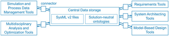
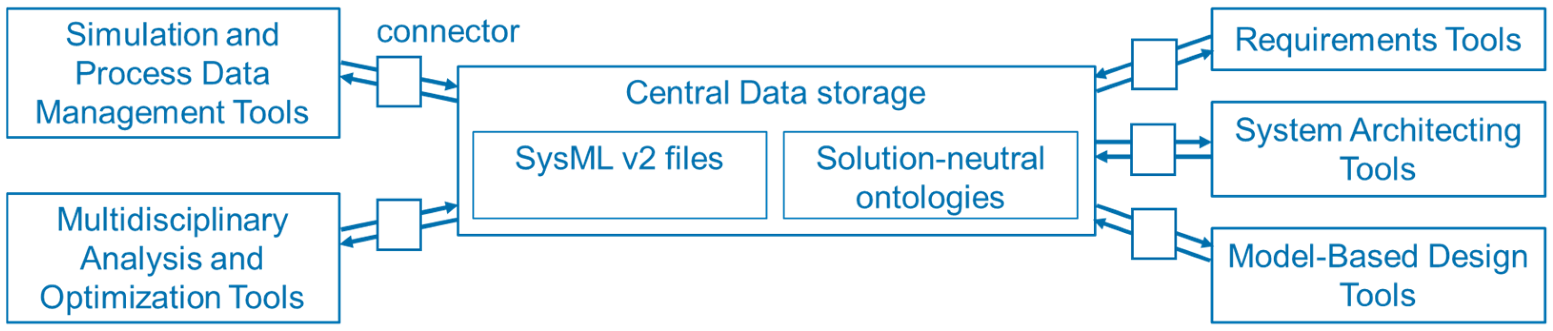
The aim of the open digital platform (ODP) is to connect tools from different domains and enable data transfer between them. New connections between tools can also be established among different vendors or open-source tools. The tools are connected to the central data storage with connectors, as presented in Figure 1.
Figure 1.
Architecture of the open digital platform.
Tools. The tools are used to support technical steps of the design process for specific domains. Starting from the requirements, the system architecture is derived. In model-based design tools, this architecture can be implemented in executable simulation models. They comprise various disciplines such as mechanical and electrical 1D simulations up to structural and fluid 3D simulations. Optimal solutions can then be found using multidisciplinary analysis and optimization tools, which can consume various models from the MBD domain. Information concerning data management is captured with SPDM tools.
Central Data Storage. Central data storage serves as the single source of truth, where all relevant data generated during product development is stored. A data schema is predefined to store the data consistently by enforcing a uniform structure and standardized relationships between data elements. This prevents ambiguity, reduces errors, and enables seamless integration across tools. Such consistency is a prerequisite to automate accessing, adding and manipulating the data from different tools. Solution-neutral ontologies [6] are used as the data schema. Solution-neutral means that they are independent of a specific tool but cover the relevant concepts and relations of a domain. Current domains considered in the ODP include REs, SA, MBD, MDAO and SPDM. These ontologies are implemented as SysML v2 user-defined library packages. Instance data from a specific design project is stored in SysML v2 files as well. It is structured according to solution-neutral ontologies and contains information such as specific requirements and simulation models. These instances can be seen as usages of ontology definitions, populated with data from the connected tools. The data exchange with SysML v2 is possible on different levels:
- SysML v2 Textual Notation (Concrete Syntax, file-based): The models and libraries are exchanged using the SysML v2 textual notation. This syntax is human-readable and can be parsed into a machine-readable format [7,8].
- SysML v2 Abstract Syntax (file-based): SysML v2 supports abstract model representation which can be serialized as JSON files. This format is more suitable for automated processing, but is not human-readable [7].
- SysML v2 Repository (REST API): The models and libraries can be stored in a SysML v2 repository using open-standard REST APIs. This approach offers the best support for tool integration [9].
While it is planned to explore the use of server-based exchange of SysML v2 models in the future, available implementations of the APIs are still under development. For simplicity, in this paper, the ODP is demonstrated using file-based exchange with SysML v2 textual notation.
Connectors. The connectors enable data transfer (indicated by arrows) between the tools and the central data storage by converting tool-specific data formats into the solution-neutral data schema and vice versa. They can read and write data from the storage and pass it to the tools. On the tool side, data is accessed through APIs or by parsing input and output files, if available. The connectors adhere to solution-neutral ontologies by relying on the corresponding SysML v2 libraries. Data extracted from the central storage conforms to this standard format, while outputs from domain-specific tools are transformed into this structure before being stored. Each domain tool requires a dedicated connector. In this paper, the connectors are implemented in Python 3.12, integrating the pilot implementation from OMG (Milford, MA USA) [10] and SysIDE Automator from Sensmetry (Vilnius, Lithuania) [11].
3. Proof of Concept
The ODP concept is evaluated using a simple proof of concept. Two tools, Teamcenter Simulation and Simcenter Amesim from Siemens (Munich, Germany) are connected using SysML v2 as a common exchange format. While an existing interface between these tools is available, it relies on proprietary formats (based on PLMXML [12]). In this contribution, we demonstrate how solution-neutral ontologies can replace this proprietary interface.
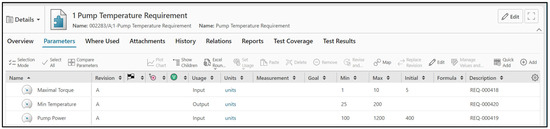
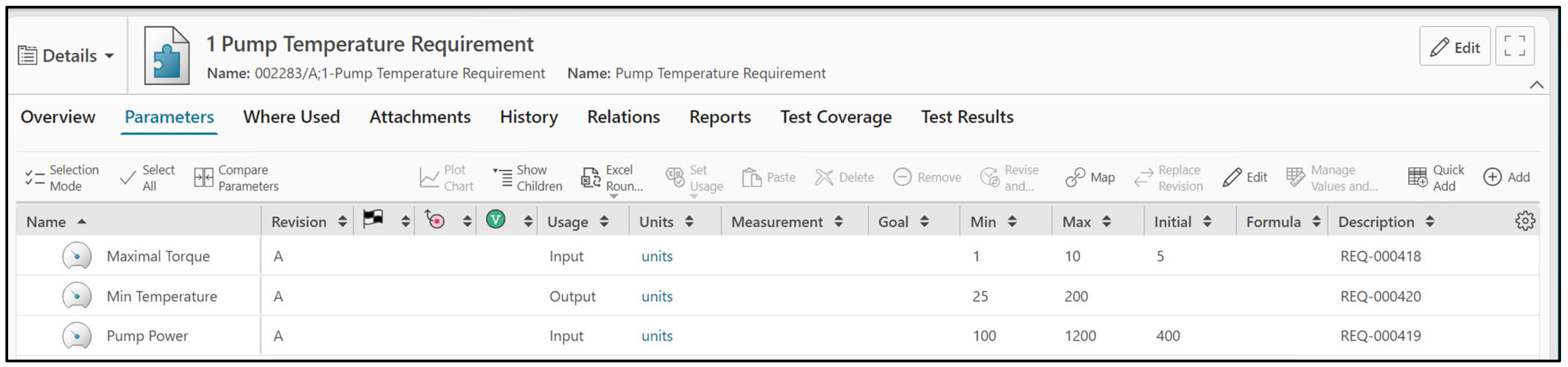
Teamcenter Simulation can manage simulation data, simulation tools and simulation workflows and is a tool from the SPDM domain [13]. It is an extension of the Teamcenter® portfolio from the PLM domain that uses digital twins and enables collaboration to manage the product lifecycle [14]. In Teamcenter Simulation, requirements can be stored, and parameters can be retrieved from the requirements, as shown in Figure 2. A simulation request can be created to run an already existing simulation model or to create a new simulation model to test a set of requirements with predefined boundary conditions. In this paper, the simulation request is used to test a set of requirement parameters and predefined initial values with an already created simulation model. A simulation model from Simcenter Amesim is linked to the simulation request and its associated parameters derived from the requirements. Parameters and variables from the simulation model are mapped to these requirement parameters to ensure consistency and traceability.
Figure 2.
Requirement parameters in Teamcenter Simulation.
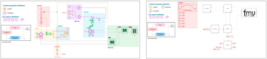
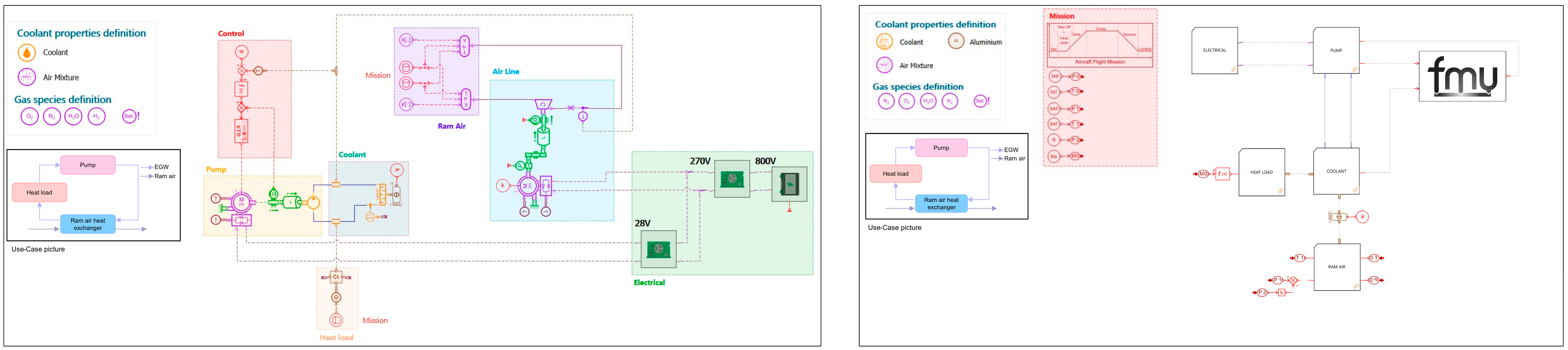
Simcenter Amesim is used within the context of MBD and provides a simulation platform for analyzing and optimizing mechatronic systems [15]. Behavioral models are created in this simulation tool using an extensive library of components that can be added to a simulation and are interconnected through ports. Groups of components (marked with colored rectangles) can be aggregated into supercomponents. Components and supercomponents can have multiple input parameters and output variables, as seen in Figure 3. To ensure that the connector generates the correct syntax with all essential information, the Simcenter Amesim model must be properly configured. The connector captures information at the supercomponent level, but not at the individual component level.
Figure 3.
Simulation model in Simcenter Amesim. (Left) Detailed model, (Right) same model, but grouped into supercomponents. The connector operates at the supercomponent level and does not extract details of individual components.
With the connectors for these tools, the use case of a thermal management system (TMS) was tested. The TMS proposed in this work is focused on the heat exchange between Ram Air, which picks air from outside, and the aircraft’s heat load via a coolant circuit (EGW coolant). A pump is directly controlled to maintain the target temperature by adjusting the coolant flow. The control logic for the pump is included, along with the electrical subsystem to estimate pump power consumption. The TMS model proposed can be simulated over an entire aircraft mission. It was designed to cover multiple domains through different blocks and their interactions. The behavioral model is implemented in Simcenter Amesim and illustrated in Figure 3.
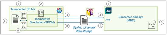
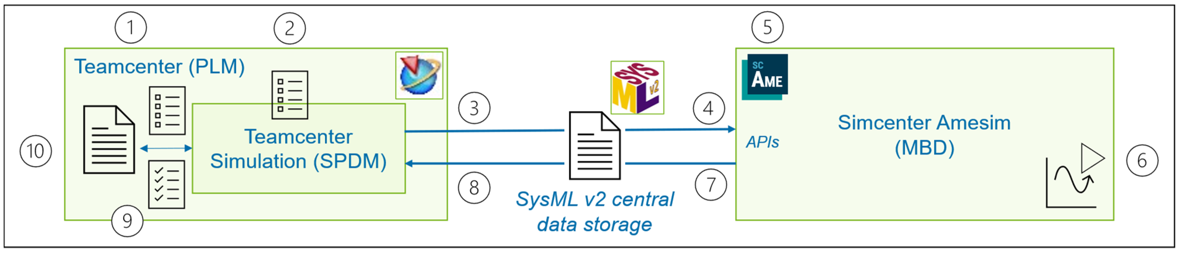
The workflow for the proof of concept begins in Teamcenter Simulation, exchanges information with Simcenter Amesim through SysML v2, and then feeds the results back into Teamcenter Simulation. The workflow is shown in Figure 4.
Figure 4.
Workflow of the proof of concept.
To execute the workflow, the following steps are performed:
- Model and store requirements: The requirements of the System of Interest are modeled and stored. They can be imported from a word document or directly created in Teamcenter Simulation. The requirements contain parameters with goal values, a permissible range and units.
- Create verification and simulation request: The requirements to be tested are selected and a verification request is created. A simulation request is derived from this verification request, and a simulation model is selected that is used to test the selected requirements virtually. Each parameter from the requirements is mapped to a parameter or variable from the simulation model. Initial values that serve as input values for the simulation model are defined.
- Convert to SysML v2 format: The information from the simulation request is converted into a SysML v2 file using the Teamcenter Simulation connector. The requirements with the initial values and the simulation request with the connected simulation model are stored in the file.
- Set initial values in Simcenter Amesim: The Simcenter Amesim connector reads the initial values from the SysML v2 file and uses the Simcenter Amesim API to set these values in the simulation model.
- Prepare the simulation model: In this case, the simulation model already exists, and the initial values can be set.
- Run the simulation: The behavioral model is executed. The initial values given by the SysML v2 file are consumed and the simulation results are computed.
- Store simulation results in SysML v2 format: The simulation results are saved in the SysML v2 text file by using the Simcenter Amesim connector. In addition, information about the simulation model’s structure, like the supercomponents, ports, parameters and variables, is stored.
- Import results into Teamcenter Simulation: The simulation results from the SysML v2 file are imported into Teamcenter Simulation with the Teamcenter Simulation connector.
- Update the simulation request: The simulation results are directly stored in the simulation request that was created in Teamcenter Simulation.
- Compare results with requirements: In Teamcenter Simulation, the simulation results are compared to the requirements from the simulation request. There is visual feedback on whether the requirements are met with the linked simulation model and the predefined initial values. If needed, a new iteration can be performed.
In addition to this workflow, it is also possible to exchange other information through the SysML v2 file. If the simulation model is not yet created, it is also possible to receive information about the model’s structure from a SysML v2 file and create, validate and verify the behavioral model with the provided information.
4. Results and Discussion
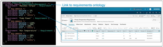
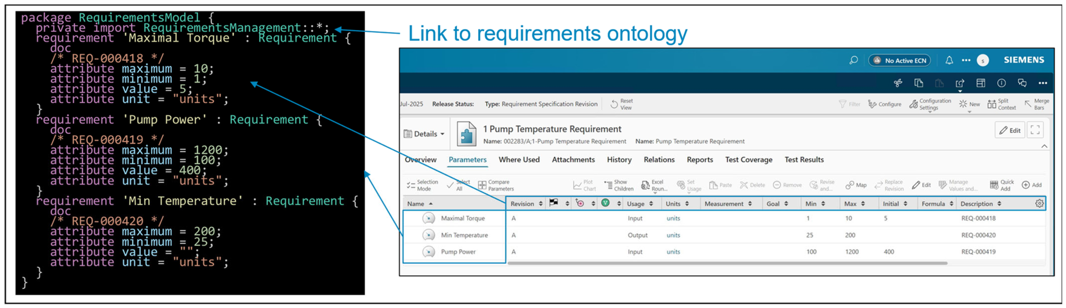
As a result, data from the tools is stored in the SysML v2 data schema. Moreover, data from the SysML v2 files in the data storage is used to extract information and transfer it to the tools. In Figure 5, the SysML v2 code for the requirements is shown. Each requirement from Teamcenter Simulation is automatically transferred into SysML v2 by using the Teamcenter Simulation connector. Attributes regarding the parameters are included. The “value” attributes can serve as initial values for the Simcenter Amesim models.
Figure 5.
SysML v2 code produced from the Teamcenter Simulation connector and representing the requirements.
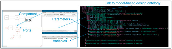
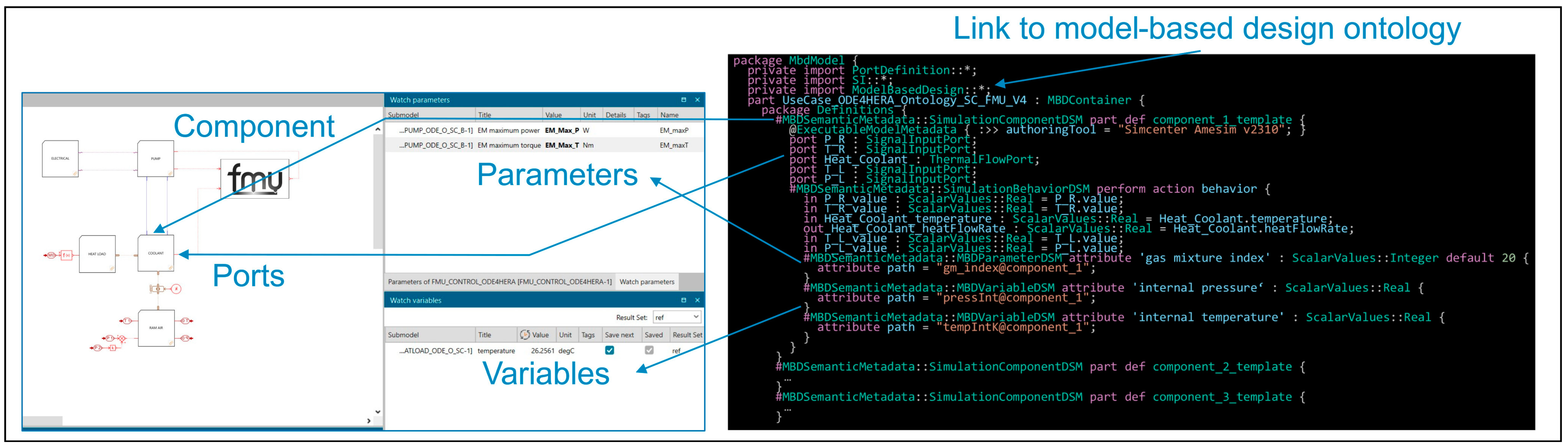
SysML v2 code is also generated for the Simcenter Amesim model, as seen in Figure 6. In this case, a SysML v2 library with SI units and the customized library for model-based design is imported. The simulation model is represented in the SysML v2 file according to the MBD ontology. For example, supercomponents from the simulation model are associated with “SimulationComponentDSM” from the MBD ontology, meaning that each supercomponent is automatically associated with this metadata in the SysML v2 file. To read information out of the MBD file, these keywords can be used to search for specific information. Each supercomponent is automatically captured in the SysML v2 file with its ports, port values, parameters, and variables. The initial values and the simulation results are stored as values of the respective parameters or variables.
Figure 6.
SysML v2 code produced from the Simcenter Amesim connector representing the behavioral model structure.
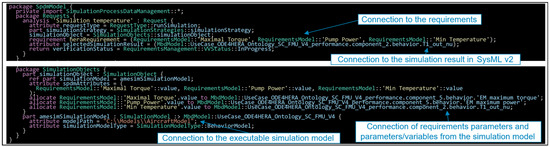
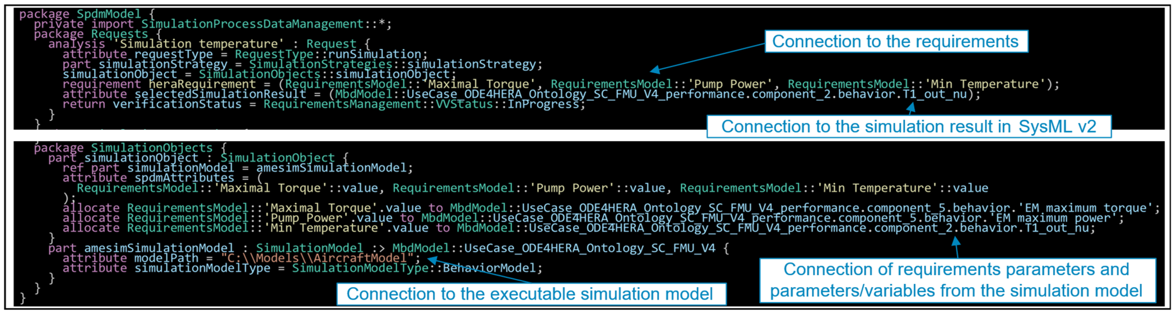
Both the requirements from Teamcenter Simulation and the simulation model from Simcenter Amesim are connected through the simulation request in Teamcenter Simulation. The purpose of the simulation request is to verify the requirements but also to save the connections between the requirements and the simulation model. The SysML v2 code is shown in Figure 7. The requirements from the requirements package and the simulation result from the MBD package are referenced in the SPDM package. Most important is the connection between requirement parameters and variables from the simulation model as allocations. They were already defined in the simulation request. For other tools without the capability to connect parameters from different tools, a solution is needed. Additionally, a link to the local executable model is given.
Figure 7.
SysML v2 code produced from the Teamcenter Simulation connector representing the simulation request.
5. Conclusions and Outlook
Using an ODP with central data storage and connectors for different tools enables data exchange between various tools. This was tested by using SysML v2 as the open data schema to transfer data between Teamcenter Simulation and Simcenter Amesim successfully. An exchange of initial values and the simulation result was possible. It remains open how other types of data, e.g., vectors, matrices and specific simulation result files, will be exchanged with SysML v2. It is recommended not to replace well-established formats like CPACS but instead refer to them in the SysML v2 file.
The exchange with the open standard was demonstrated for two tools. To connect a new tool, an initial effort is needed in implementing a connector to read and write the information from the SysML v2 file. Once this connection is established, data exchange with all the other connected tools is possible. Future directions can be to include other tools like 3D simulation tools. An extension of the ontologies might be useful with relevant concepts from these domains, e.g., for simulation setup and mesh data, and new connectors need to be implemented to integrate associated tools. If appropriate, existing ontologies should be reused.
The current demonstration could show how SysML v2 can serve as a common format for data exchange in the domain of SPDM and MBD. A key limitation is that the current setup relies on file-based exchange and is limited to working on a single machine setup. Now that the usefulness of SysML v2 as an exchange format is demonstrated, further investigations will focus on the integration of this workflow into a server-based architecture supported by SysML v2 APIs, which are part of the standard. The addition of online object storage for simulation files will enable true multi-user, multi-location collaboration for simulation-based design and verification.
Author Contributions
Conceptualization, K.Z., O.K., E.A., P.B. (Philippe Barabinot), J.M.L. and F.R.; methodology, K.Z., O.K., P.B. (Pierre Brionne), J.M.L. and F.R.; software, K.Z. and O.K.; validation, K.Z., O.K. and F.R.; writing—original draft preparation, K.Z.; writing—review and editing, R.P., O.K., R.W., J.M.L. and F.R.; visualization, K.Z., P.B. (Pierre Brionne) and F.R.; supervision, R.W.; project administration, P.B. (Philippe Barabinot), J.M.L. and F.R. All authors have read and agreed to the published version of the manuscript.
Funding
Co-funded by the European Union under GA no. 101140510. Views and opinions expressed are however those of the authors only and do not necessarily reflect those of the European Union or Clean Aviation Joint Undertaking. Neither the European Union nor the granting authority can be held responsible for them.
Institutional Review Board Statement
Not applicable.
Informed Consent Statement
Not applicable.
Data Availability Statement
Data is contained within the article.
Conflicts of Interest
Author K.Z., R.P., O.K., P.B. (Pierre Brionne), J.M.L. were employed by the company Siemens AG. Author E.A. was employed by the company Siemens Industry Software NV. Authors P.B. (Philippe Barabinot) and F.R. were employed by the company Siemens Industry Software SAS. The remaining authors declare that the research was conducted in the absence of any commercial or financial relationships that could be construed as a potential conflict of interest..
Credits
Simcenter™ Amesim™ software, Teamcenter® portfolio and Teamcenter® Simulation software are Siemens trademarks.
References
- Context and Challenges. Available online: https://www.ode4hera.eu/context-and-challenges (accessed on 5 November 2025).
- Manuse, J.E.; Sniezek, B. On the Perception of Complexity and Its Implications. In Transdisciplinary Perspectives on Complex Systems; Kahlen, F.-J., Flumerfelt, S., Alves, A., Eds.; Springer International Publishing: Cham, Switzerland, 2017; pp. 213–269. [Google Scholar]
- Alder, M.; Moerland, E.; Jepsen, J.; Nagel, B. Recent Advances in Establishing a Common Language for Aircraft Design with CPACS. In Proceedings of the Aerospace Europe Conference 2020, Bordeaux, Frankreich, 25–28 February 2020. [Google Scholar]
- Friedenthal, S. Future Directions for MBSE with SysML V2. In Proceedings of the 11th International Conference on Model-Based Software and Systems Engineering; SciTePress: Lisbon, Portugal, 2023; pp. 5–9. [Google Scholar] [CrossRef] [Scilit]
- Bajaj, M.; Friedenthal, S.; Seidewitz, E. Systems Modeling Language (SysML v2) Support for Digital Engineering. Insight 2022, 25, 19–24. [Google Scholar] [CrossRef] [Scilit]
- Bussemaker, J.; Torrigiani, F.; Cabaleiro, C. HERA Architecture Framework Libraries (1.0). 2026. Available online: https://zenodo.org/records/18267043 (accessed on 11 November 2025).
- OMG Systems Modeling LanguageTM (SysML®). Available online: https://github.com/Systems-Modeling/SysML-v2-Release/blob/master/doc/2a-OMG_Systems_Modeling_Language.pdf (accessed on 11 November 2025).
- Introduction to the SysML v2 Language Textual Notation. Available online: https://github.com/Systems-Modeling/SysML-v2-Release/blob/master/doc/Intro%20to%20the%20SysML%20v2%20Language-Textual%20Notation.pdf (accessed on 11 November 2025).
- Systems Modeling Application Programming Interface (API) and Services. Available online: https://github.com/Systems-Modeling/SysML-v2-API-Services (accessed on 11 November 2025).
- SysML-v2-Pilot-Implementation. Available online: https://github.com/Systems-Modeling/SysML-v2-Pilot-Implementation (accessed on 5 November 2025).
- Vaicenavičius, J.; Wiklund, T.; Kavolis, D.; Draukšas, S.; Kalkauskas, A.; Vaicenavičius, R. SysIDE: SysML v2 Textual Editing and Analysis System: Overview and Applications. CEAS Space J. 2025. [Google Scholar] [CrossRef] [Scilit]
- PLM XML. Available online: https://plm.sw.siemens.com/de-DE/plm-components/plm-xml/ (accessed on 28 October 2025).
- Simulation Process and Data Management (SPDM) with Teamcenter Simulation. Available online: https://resources.sw.siemens.com/de-DE/fact-sheet-simulation-process-and-data-management-spdm-with-teamcenter-simulation/ (accessed on 12 November 2025).
- Teamcenter PLM Software. Available online: https://plm.sw.siemens.com/en-US/teamcenter/ (accessed on 12 November 2025).
- Simcenter Amesim Software. Available online: https://plm.sw.siemens.com/en-US/simcenter/systems-simulation/amesim/ (accessed on 12 November 2025).
Disclaimer/Publisher’s Note: The statements, opinions and data contained in all publications are solely those of the individual author(s) and contributor(s) and not of MDPI and/or the editor(s). MDPI and/or the editor(s) disclaim responsibility for any injury to people or property resulting from any ideas, methods, instructions or products referred to in the content. |
© 2026 by the authors. Licensee MDPI, Basel, Switzerland. This article is an open access article distributed under the terms and conditions of the Creative Commons Attribution (CC BY) license.