


Abstract
This research work is aimed at developing and manufacturing thermoplastic-composite parts for a Type V hydrogen storage tank based on a patented design. A 57% fibre volume fraction of a carbon fibre and polyamide 11 (PA11) thermoplastic matrix was used in an automated tape layup (ATL) process to manufacture a laser-assisted in situ-consolidated composite part for a hydrogen storage vessel. A series of mechanical and thermal tests were performed to optimize the process parameters for composite manufacturing. Based on the optimized process parameters, a scaled-up demonstrator composite part was manufactured and demoulded using pressurized air.
1. Introduction
As the demand for hydrogen gas as a fuel continues to grow, researchers are focusing on developing advanced materials that are both lightweight and durable, capable of safely storing hydrogen in its liquefied state at cryogenic temperatures. Hydrogen exists as a diatomic molecule with the smallest molecular diameter in the atmosphere; therefore, the materials used for its containment must possess high gas permeability resistance to prevent leakage and ensure safety. Carbon fibre composites are lightweight and widely used materials for high-pressure hydrogen storage, offering customized properties to meet specific operational requirements [1,2,3]. Hydrogen storage vessels are classified into five types based on the proportion of composite material used. Type I cylinders are entirely metallic, typically fabricated from aluminium or steel alloys such as Al 6061, AA7175, and AA6XX series [4]. Type II and Type III designs incorporate filament-wound carbon or glass fibres, applied either to the dome region or across the entire vessel, respectively. Type IV tanks employ a polymer liner reinforced with carbon or glass fibres through tow winding. Type V represents fully composite structures without any liner. As the composite content increases across these categories, the gravimetric efficiency of the storage system improves correspondingly [5].
The permeability of gases (particularly hydrogen) in Type IV and Type V pressure vessels is critical in ensuring the safety, performance, and longevity of high-pressure storage systems. The U.S. Department of Energy’s Hydrogen Program specifies that the permissible hydrogen permeation rate for carbon composite pressure vessels is 0.05 (g/h)/kg [6]. Key factors affecting hydrogen permeability in these tanks include operating temperature, internal pressure, and the intrinsic properties of the composite materials used [7].
Project OVERLEAF (The OVERLEAF cryogenic tank for storing H2 in liquid form is patent-protected, based on a concept protected by an Aciturri patent (European Patent Number 22 382 492.1.) is aimed at developing a Type V cryogenic liquid-hydrogen storage tank with a working pressure of 6 bar. The overall tank consists of two major components: a 3D-printed inner tank and a thermoplastic-composite outer tank. The outer tank acts as a structural support with a low burst pressure of 350 MPa. The material used was carbon fibre as reinforcement and polyamide 11 (PA11) as the matrix in unidirectional (UD) tape. An automated tape layup (ATL) technique with a 6 kW laser as the heating source was used to manufacture the composites with a quasi-isotropic layup sequence.
2. Material Characterization
PA 11-impregnated carbon fibre UD tapes developed by Arkema® (Serquigny, France) and sourced from Suprem® (Suprem 11701, Yverdon-les-Bains, Switzerland), having a width of 12.7 mm and 57% fibre volume content, were characterized by single-lap shear (SLS) to optimize process parameters [8] and used to manufacture the final composite part. The PA11 thermoplastic resin formulation of Arkema®, having a 150 Pa.s viscosity, was specifically developed to resist traverse microcracking at a cryogenic temperature of 120 K.
2.1. Thermal and Optical Characterization
The glass transition temperature (Tg), melting temperature (Tm) and crystallinity of the unprocessed CF|PA11 tapes were measured according to the UNE-EN ISO 11357 test standard [8] using Digital Scanning Calorimetry (DSC) Q20 V24.10 Build 122™ from TA Instrument® (New Castle, DE, USA). The samples were subjected to a pre-drying cycle of 80 °C for 6 to 8 h. After this step, a nitrogen atmosphere was used and the samples were heated to 250 °C at a heating rate of 10 °C/min, held isothermally for 15 min, and cooled down at a rate of 10 °C/min.
Microstructural analysis of the processed and unprocessed CF|PA11 tape was carried out on OLIMPUS GX71™ (Tokyo, Japan) microscope. At 100- and 500-times magnification, the results were used to determine the porosity.
2.2. Mechanical Characterization
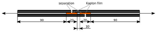
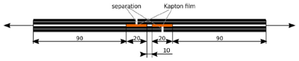
Simplified single-lap shear test samples of 230 mm × 25 mm were manufactured with 0 ply fibre orientation and 25 mm × 10 mm shear zone as shown in Figure 1. Based on the DSC test results and manufacturer’s recommendation, the ATL process parameters, ranging in nip point temperature, layup speed and compaction force, as shown in Table 1, were used to manufacture 9 samples.
Figure 1.
Simplified single-lap shear test schematic [9].
Table 1.
ATL process parameters for SLS test.
3. Technical Infrastructure
3.1. ATL Machine
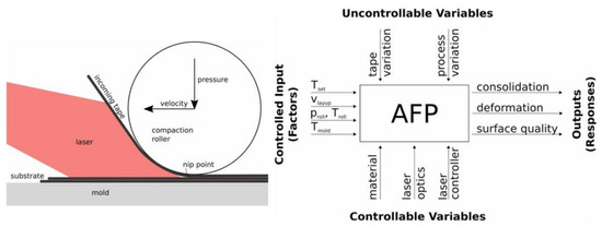
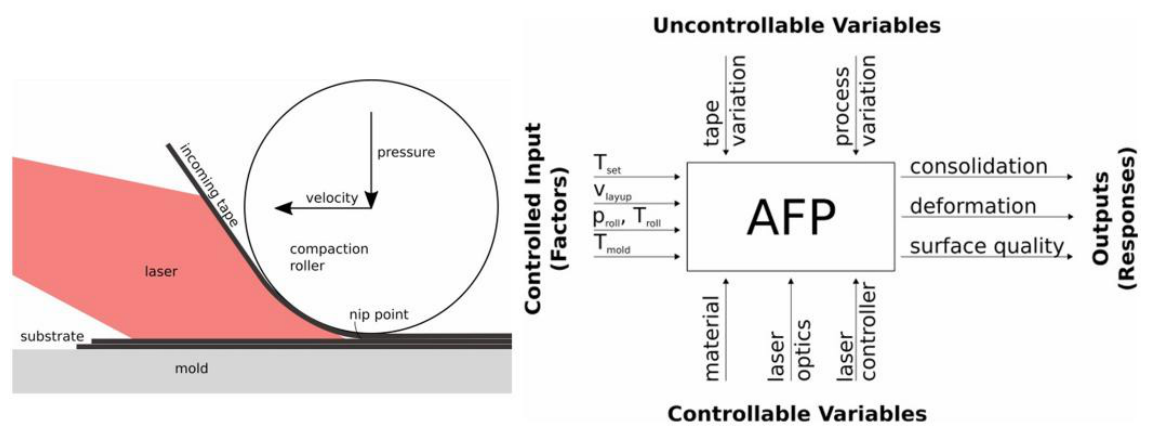
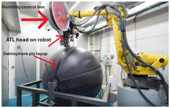
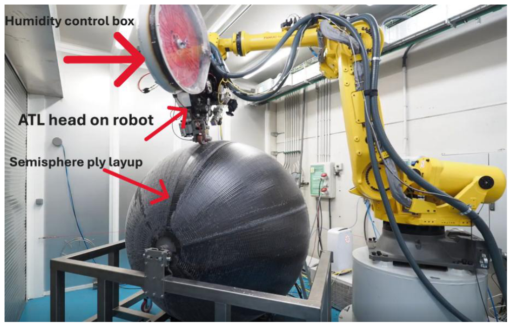
A Conbility® ATL head mounted on a FANUC® R-2000iC/165Fi™ 6-axis robot (FANUC Corporation, Yamanashi, Japan) with a Laserline® (Laserline GmbH, Mülheim-Kärlich, Germany) 6 kW diode laser heater was used to automate the manufacturing of the composites. Pyrometer-based closed-loop control was used to avoid overheating of the tapes. As the moisture absorption of PA11 affects the warping effect in composites, a humidity control chamber was designed to keep the UD tapes at a constant 60 °C temperature. Figure 2 shows the complete setup of the tape-laying system.
Figure 2.
ATL process schematic [10].
CAM Process Chain
The workflow included importing ply layup in Rhino® (McNeel Europe S.L., Barcelona, Spain), ply design, process simulation, collision analysis and path planning, all of which was carried out in ADDPath™ (Addcomposites Oy, Espoo, Finland). The path planning programs generated were validated offline on 8 axes of the robot (6-axis robot native and 2 external rotary axes) to match the simulation and collision detection.
3.2. Tooling for Semi-Sphere Manufacturing
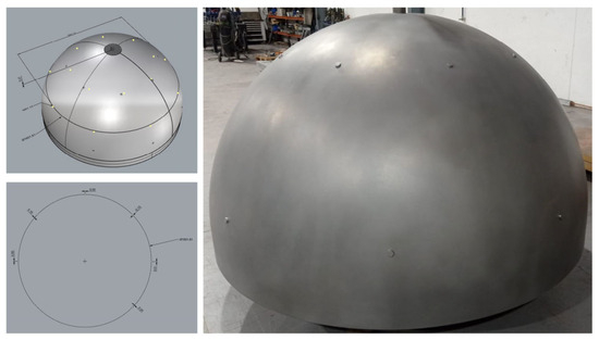
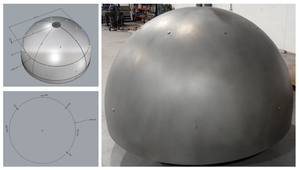
Aluminium alloy EN AB46400 was used to cast the Semi-sphere tooling as shown in Figure 3 and machined to the final dimensions of 1796 mm diameter and 1017 mm height. In total, 16 ejection holes of 24 mm diameter, evenly distributed over the tooling surface, were machined to enable 8 bar air pressure for demoulding of the finished composite part. A surface tolerance study showed that the geometry variance was 0.45 mm in height and 0.68 mm in diameter, which was within acceptable limits. To facilitate the rotation of the mould for Semi-sphere manufacturing, it was supported on a steel frame with castor wheels. This setup also enabled mounting of lathe cutting tools to machine the composite to the engineered end of part (EEoP).
Figure 3.
CAD model (left up), tolerance study (left down) and aluminium casting (right).
4. Results and Discussion
4.1. Material Characterization
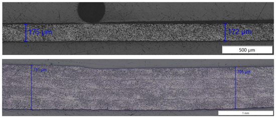
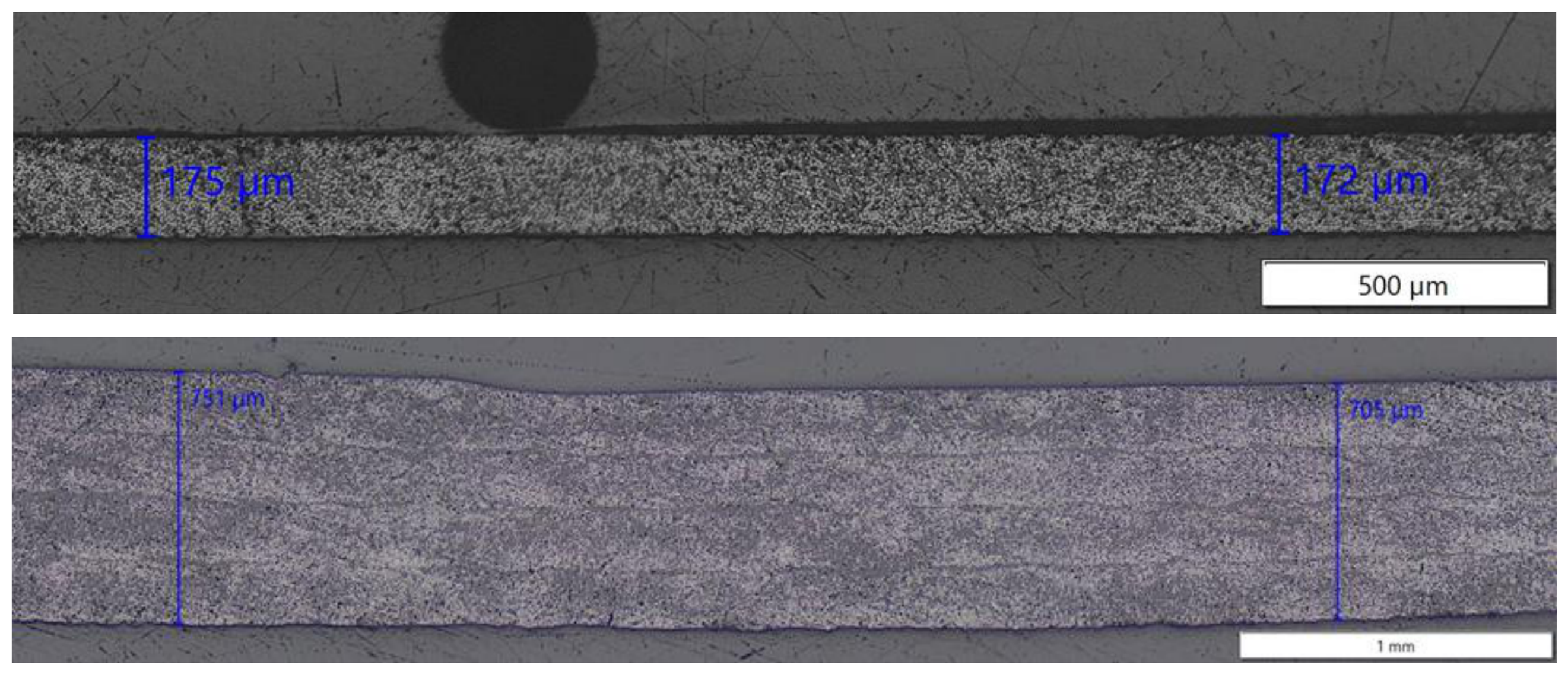
The DSC results showed a Tm of 188.45 °C, a Tg of 94.44 °C and 22% crystallinity with a fusion enthalpy of 18.89 J/g. The microstructural characterization, as shown in Figure 4, showed homogeneity throughout the thickness, no voids or other fibre/resin defects, and porosity of less than 1%.
Figure 4.
Cross-section of CF|PA11: Top, UD tape; bottom, ATL processed composite.
The SLS tests are presented in Table 2. Due to the relatively high viscosity of the resin, with an increase in the layup speed, the bond strength decreases; thus, to optimize between the bond strength and production speeds, the combination of 300 °C and 200 mm/s speed was chosen for the component manufacturing.
Table 2.
SLS results from the process analysis [11].
4.2. Semi-Sphere Manufacturing
The manufacturing of two Semi-spheres was completed with 200 h of manufacturing with a total of 68 kg of CF|PA11 tape material. A total of 40 layers were deposited by the ATL head as shown in Figure 5, with the majority of ply angles in three directions, viz. 90° and ±7°. The ply layup was designed so that there is a progressive increase in the thickness from the equator (4 mm) to the pole (8 mm).
Figure 5.
ATL of Semi-sphere.
4.2.1. First Ply Layup
The adhesion of the first ply to the aluminium mould was done using the process parameters and robotic path plan programming described in the previous section. Double-sided adhesive Kapton™ tapes were placed on the mould such that the start and end of the placed tape remain in position, as adhesion between CF|PA11 and the metal is low.
4.2.2. Challenges During Manufacturing
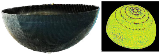
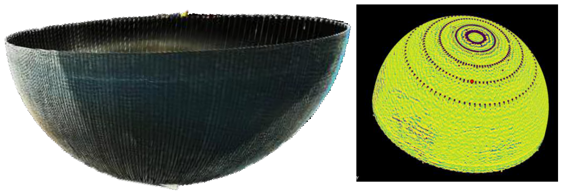
The major challenge during manufacturing was to plan robot movements for tape trajectories on a double-curve surface such that the tapes adhere fully without wrinkles or defects. At some points, especially near the pole, maintaining the gaps and overlaps in the tolerance limit of ±5 mm as per the composite design criteria was a challenge due to collision of the ATL head with the mould and the walls of the cell. This was mitigated by making changes in the robot program manually. Another challenge was to maintain the nominal tape angle of ±7°. Due to the double curvature of the Semi-sphere, the tape angle constantly deviated, due to which an error of ±1° led to the opening of a gap 7–10 mm wide between the tapes. This was mitigated by increasing the point density in the robot program for higher precision of the ATL. An in-house-developed software, Smarthub (version 4.2), was used to capture the processing parameters, viz. temperature, speed, compaction pressure and location coordinates of the tapes during layup, shown in Figure 6, for generating a digital twin of the Semi-sphere.
Figure 6.
Outer-tank composite Semi-sphere (left) manufactured by ATL; (right) digital twin [thermal map].
4.2.3. Cutting of EEoP and Demoulding
Cutting the final dimensions of the Semi-sphere was done by a diamond-coated drill bit. The machining at the pole and equator was done by rotating the Semi-sphere while keeping the drill stationary. Once the final dimensions of the Semi-sphere were achieved, demoulding of the part was carried out by supplying pressurized air at 2 bar through the inlet holes on the mould. Due to stress build-up during ATL manufacturing, the Semi-sphere part contracts in diameter and thus makes it difficult to demould mechanically, so the pressurized-air demoulding technique was used. The final part, as shown in Figure 6, was deburred at the edges and cleaned with propanol.
5. Conclusions
In this research work, manufacturing of a Type V hydrogen storage vessel component of the outer tank from CF|PA11 thermoplastic composite was carried out using an ATL with a 6 kW laser heating source, to demonstrate scale-up of the process optimization. In the first stage, the process parameters for the CF|PA11 material were optimized by conducting mechanical, thermal and optical tests. With the optimized process parameters, the scaled-up outer-tank component was manufactured on aluminium alloy tooling with progressive thickness increase from 4 mm at the equator to 8 mm at the pole. The final part was machined using a diamond-coated drill bit and demoulded using pressurized air at 2 bar. The following conclusions can be derived from this work:
- (a)
- The parameters of 300 °C temperature, 200 mm/s speed and 500 N compaction force are optimum for processing CF|PA11 given the relatively high viscosity of 150 Pa.s.
- (b)
- The robot path planning simulation is accurately able to detect collisions, especially in the pole region of the mould, which enables the planning of corrective actions in the offline robot programming.
- (c)
- In-house software Smarthub is able to successfully capture the online process parameters and generate a digital twin of the composite. A diamond-coated drill bit and pressurized air at 2 bar are successful techniques for machining and demoulding CF|PA11 thermoplastic composites without damaging the component.
For further research, effects of factors such as humidity in the tape, laser power uniformity, thermal gradient and tool temperature on the consolidation degree of the composite could be studied. In addition, to increase the production rate and efficiency, a multi-tow layup approach on complex geometries could be explored.
Author Contributions
Conceptualization, P.S. and P.R.-R.; methodology, B.G. and M.I.C.; software, P.S.; validation, B.G., M.F.-P. and M.I.C.; formal analysis, P.S. and P.R.-R.; investigation, B.G., P.S., M.F.-P. and M.I.C.; resources, P.R.-R.; data curation, P.S. and M.I.C.; writing—original draft preparation, P.S. and B.G.; writing—review and editing, P.R.-R.; visualization, M.F.-P., P.S. and M.I.C.; supervision, P.R.-R.; project administration, P.R.-R. and P.S.; funding acquisition, P.R.-R. All authors have read and agreed to the published version of the manuscript.
Funding
This research was funded by HORIZON EUROPE project Overleaf (Project ID 101056818).
Institutional Review Board Statement
Not applicable.
Informed Consent Statement
Not applicable.
Data Availability Statement
No data available.
Conflicts of Interest
The authors declare no conflicts of interest and that the funders had no role in the design of the study; in the collection, analyses, or interpretation of data; in the writing of the manuscript; or in the decision to publish the results.
Abbreviations
The following abbreviations are used in this manuscript:
| ATL | Automated Tape Layup |
| CF | Carbon Fibre |
| EEoP | Engineered End of Part |
| PA11 | Polyamide 11 |
| UD | Unidirectional |
References
- Hamori, H.; Kumazawa, H.; Higuchi, R.; Yokozeki, T. Gas permeability of CFRP cross-ply laminates with thin-ply barrier layers under cryogenic and biaxial loading conditions. Compos. Struct. 2020, 245, 112326. [Google Scholar] [CrossRef] [Scilit]
- Air, A.; Oromiehie, E.; Prusty, B.G. Design and manufacture of a Type V composite pressure vessel using automated fibre placement. Compos. Part B Eng. 2023, 266, 111027. [Google Scholar] [CrossRef] [Scilit]
- Roh, H.S.; Hua, T.Q.; Ahluwalia, R.K. Optimization of carbon fibre usage in Type 4 hydrogen storage tanks for fuel cell automobiles. Int. J. Hydrogen Energy 2013, 38, 12795–12802. [Google Scholar] [CrossRef] [Scilit]
- Alves, M.P.; Gul, W.; Junior, C.A.C.; Ha, S.K. A Review on Industrial Perspectives and Challenges on Material, Manufacturing, Design and Development of Compressed Hydrogen Storage Tanks for the Transportation Sector. Energies 2022, 15, 5152. [Google Scholar] [CrossRef] [Scilit]
- Air, A.; Shamsuddoha, M.; Prusty, B.G. A review of Type V composite pressure vessels and automated fibre placement based manufacturing. Compos. Part B Eng. 2023, 253, 110573. [Google Scholar] [CrossRef] [Scilit]
- Ahluwalia, R.K.; Hua, T.Q.; Peng, J.K. On-board and Off-board performance of hydrogen storage options for light-duty vehicles. Int. J. Hydrogen Energy 2012, 37, 2891–2910. [Google Scholar] [CrossRef] [Scilit]
- Kadri, K.; Abdallah, A.B.; Ballut, S. Hydrogen Storage Vessels of Type 4 and Type 5. In Hydrogen Technologies—Advances, Insights, and Applications; IntechOpen: London, UK, 2024. [Google Scholar] [CrossRef] [Scilit]
- UNE-EN ISO 11357-1:2023; Plastics—Differential Scanning Calorimetry (DSC)—Part 1: General Principles. International Organization for Standardization (ISO): Geneva, Switzerland, 2023.
- Dreher, P.N.; Chadwick, A.R.; Nowotny, S. Optimization of in-situ thermoplastic automated fibre placement process parameters through DoE. In Proceedings of the SAMPE Europe, Nantes, France, 17–19 September 2019. [Google Scholar]
- Dreher, P.N.; Chadwick, A.; Doll, G. Optimization of DDP test parameters through DoE for AFP process improvement. In Proceedings of the ITHEC 2018 Conference, Bremen, Germany, 30–31 October 2018; pp. 179–182. [Google Scholar]
- Shimpi, P.; Ion-Ebrasu, D.; Pedrera, M.; Coto, I.; Gomes, B.; Rodriguez, P. Automated manufacturing of thermoplastic composites for hydrogen storage. In Proceedings of the Materiales Compuestos (2025), MatComp25, Barcelona, Spain, 8–10 July 2025; Volume 9. Available online: https://www.scipedia.com/public/Shimpi_et_al_2025a (accessed on 8 July 2025).

Disclaimer/Publisher’s Note: The statements, opinions and data contained in all publications are solely those of the individual author(s) and contributor(s) and not of MDPI and/or the editor(s). MDPI and/or the editor(s) disclaim responsibility for any injury to people or property resulting from any ideas, methods, instructions or products referred to in the content. |
© 2026 by the authors. Licensee MDPI, Basel, Switzerland. This article is an open access article distributed under the terms and conditions of the Creative Commons Attribution (CC BY) license.