


Abstract
Thin-walled tubes and beams are widely adopted for their excellent stiffness-to-weight performance. When subjected to bending, their structural response is governed by cross-section deformation (in-plane warping) that classical beam theories neglect. This work proposes a method based on deformation modes aimed at predicting the deformation of the cross-section of thin-walled members subjected to pure bending. The objective is to capture the in-plane warping mechanisms that drive stiffness degradation and nonlinear moment–curvature behavior with a computationally light and physically interpretable model. The method represents the cross-section kinematics through a combination of a set of deformation modes and determines their amplitudes by minimizing the total potential energy under geometrically nonlinear kinematics of the tube. The approach comprehends large rotations, applies to both closed and open sections, and can be applied to a tube with a generic cross-section. Representative applications show that the model reproduces the progressive in-plane deformation of closed circular and U open tubes, yielding moment–curvature curves consistent with reference solutions. The proposed method offers a practical analytical reference for predicting cross-section deformation of tubes under a finite bending regime and provides a bridge between classical one-dimensional theories and high-fidelity shell formulations.
1. Introduction
Thin-walled tubes and beams have long been recognized as essential building blocks in many branches of engineering. They are employed in civil infrastructures, in the aerospace and naval industries, in the automotive field, as well as in energy transportation systems such as pipelines and offshore risers [1,2,3,4]. What makes these elements so widely used is a combination of properties that are not easily achieved with solid members: reduced weight, efficient use of material, adequately flexural and torsional capacity, together with a relative ease of fabrication. The spread of lightweight design attitudes, in particular, has pushed further the interest in thin-walled components, since the balance between stiffness and mass has become a key performance indicator in many technological areas.
However, it is important to stress that the same geometrical features that provide efficiency also introduce highly nonlinear mechanical behaviors. Because the wall thickness is much smaller than the other characteristic dimensions, these members are particularly prone to local phenomena that can significantly influence their structural response. In practice, even when global displacements are not excessively large, distortions of the cross-section may occur and alter the effective stiffness of the structural element [5,6,7,8]. These distortions, usually referred to as warping, ovalization, or sectional distortion depending on the geometry of the mechanical element and on the deformation mechanism involved, have been extensively discussed in the classical theory of thin-walled bars and structures [9,10,11]. Nevertheless, they are usually neglected in classical linear [12,13,14] and nonlinear [15,16,17,18,19,20] beam theories, although they cannot be ignored when thin-walled tubes and beams are subjected to bending or torsion.
The influence of cross-section deformation on the overall behavior is more than a theoretical curiosity. Consider, for instance, long pipelines deployed in offshore installations, where during laying or arrangement operations they may be forced into configurations with large curvature [21,22,23]. If the section deforms, the bending stiffness decreases and the load–curvature relation deviates from the predictions of simple beam models. Similar situations arise in aircraft or ship structures, where thin stiffeners or frames undergo complex combinations of bending and torsion, and in automotive applications, where lightweight tubular components are required to sustain high loads under crash conditions. In all these scenarios, the capacity to foresee the real deformation patterns is closely tied to the safety and reliability of the structure.
Traditionally, the mechanics of beams has relied on the assumption of rigid cross-sections, leading to well-known theories such as those of Euler–Bernoulli or Timoshenko. These theories are extremely successful when thickness is not negligible and the geometry does not favor distortional modes. However, they fall short when the local deformation of the section plays a central role. The need to go beyond such classical frameworks has led, especially in the second half of the last century, to the development of refined models for thin-walled members. Among them, the Generalized Beam Theory (GBT) occupies an important place [24,25,26,27]. The GBT extends the concept of beam modeling by expressing the displacement field of the section as a superposition of predefined deformation modes. Each mode has a specific mechanical meaning, such as uniform torsion, local distortion, or global bending. By combining them, one can represent a rich spectrum of behaviors while still retaining a one-dimensional description along the beam axis. This approach has proven efficient since the number of degrees of freedom is drastically reduced compared to full shell or solid discretization. Over the years, GBT has been enriched to cover a variety of cases, including composite materials, stability problems, and post-buckling analyses.
Despite its many advantages, GBT has inherent limitations. The definition of modes is tied to the undeformed configuration, and the theory essentially combines them in a linear way since the formulation is mainly aimed at linear or weakly nonlinear analyses. As a consequence, strongly nonlinear phenomena, such as those occurring in finite bending of thin-walled tubes and beams, where the geometry itself evolves significantly during loading, are only partially captured.
On the opposite side of beam and GBT modelling lie nonlinear shell theories. Starting from the pioneering works of Chien [28,29,30,31] and Reissner [32,33,34], and the recent paper of of Iandiorio and Salvini [35], a mathematically rigorous description of shells under large displacements and rotations has been established. Classical and nonlinear shell theories provide the high-fidelity mechanical background for this class of finite-rotation, small-strain problems [36,37,38,39]. These theories, often based on intrinsic geometrical formulations, are capable in principle of describing any kind of large deformation, without restrictions on rotations or displacements. They rely on tools such as curvature tensors and differential geometry, and they provide a complete framework to address nonlinear shell mechanics. However, the resulting formulations typically lead to strongly nonlinear differential equations which can be challenging to solve in practice, even with advanced numerical schemes.
Therefore, usually, to address the design of thin-walled structures, engineers have tended to favor computational methods, particularly finite element (FE) models based on shell elements. These are versatile, widely implemented in commercial codes, and capable of handling arbitrary geometries and boundary conditions. However, they come with significant computational cost, especially when used to explore nonlinear responses in a large parameter space, e.g., thickness, material stiffness, geometry, etc. In addition, although Finite Element Analysis (FEA) can deliver detailed stress fields, it may obscure the connection between the observed behavior and the underlying deformation mechanisms, much like a black box would do.
A classic example of why it is important to accurately design a thin-walled structure is provided by the so-called Brazier effect [5,6,7]. When a thin-walled circular tube is bent, the cross-section tends to ovalize. This ovalization reduces the second moment of area, and hence the bending stiffness, in a progressive way. As the curvature increases, the bending moment initially rises but eventually reaches a maximum and then decreases, defining a critical load associated with instability. Brazier’s original analysis, although approximate, captured this essential phenomenon and highlighted how the deformation of the cross-section cannot be overlooked. Subsequent refinements by many authors, both analytically, numerically and experimentally, confirmed the relevance of ovalization in practical cases. Yet, most of these works were tailored to circular sections and to specific conditions, leaving open the question of how to generalize the understanding to other shapes or to large-displacement regimes.
The present contribution situates itself precisely in this landscape. Our aim is to introduce a modal method capable of predicting, for an arbitrary cross-section, the deformation of thin-walled tubes and beams under pure bending. Unlike approaches limited to small deformations or predefined linear combinations of modes, the proposed method is constructed within an energetic framework, based on the recent work of Iandiorio and Salvini [35] and consistent with standard variational energy methods in applied mechanics, that naturally incorporates nonlinear coupling and accounts for large displacements. The in-plane warping of the cross-section is represented through a set of modes, and the evolution of their amplitudes under loading is obtained by minimizing the total potential energy of the system. This makes it possible to describe, within a unified formulation, the progressive ovalization, the modification of stiffness, and the dimensionless nonlinear moment–curvature relations characteristic of thin-walled members in finite bending. Therefore, the ultimate goal is the same: reduce the dimensionality of the problem while keeping the essential physics in sight.
From a practical standpoint, the advantages are twofold. First, the method retains the interpretability of modal approaches in which each mode has a physical meaning and can be directly associated with observable deformation patterns. Second, the computational efficiency is significantly higher than that of full shell analyses, since the problem is reduced to the evolution of a relatively small number of modal amplitudes and can be addressed once for all by introducing dimensionless quantities.
2. The Modal-Based Energetic Approach: Mode Extraction and Variational Solution
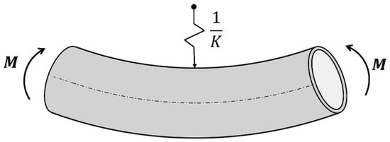
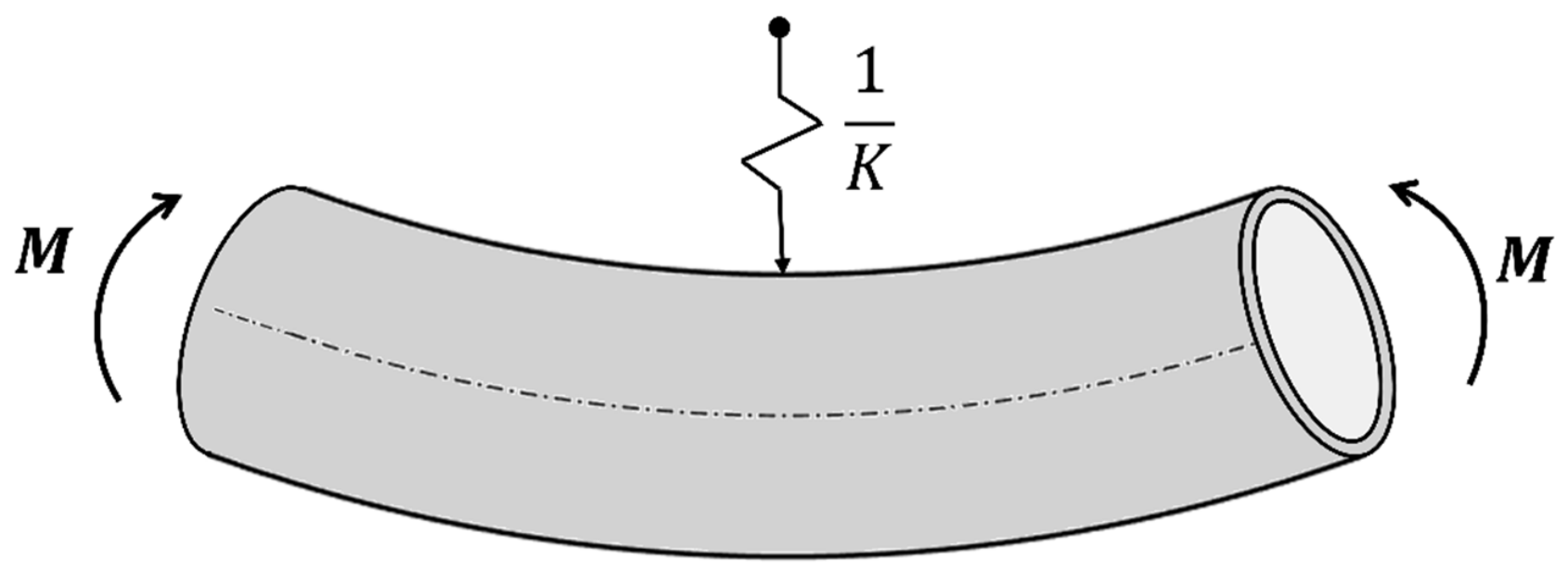
To place out the present contribution, it is useful to recall the geometrically nonlinear shell model recently proposed by Iandiorio and Salvini [35]. Their formulation is derived from an intrinsic geometry and moving frames approach, and it is explicitly tailored to thin-walled tubular members, both open and closed, subjected to large displacements and rotations, remaining in a small-strains regime. The kinematics assumes constant thickness, biaxial in-plane strains (no strains through-thickness extension), planar undeformed sections, and general curvilinear centerlines and cross-sections. Boundary effects are neglected following Saint-Venant’s principle. Within these hypotheses, they provide the full set of constitutive and equilibrium relations for thin-walled shells and then specialize the framework to pure bending (Figure 1), defining the total energy functional for an arbitrary cross-section and enforcing the stationary condition of the total energy (Euler’s Variational Principle of Least Effort) to obtain the governing equations. The resulting problem is a nonlinear ODE system accompanied by a boundary-value problem (BVP). Its solution is nontrivial in practice. To solve it, they recast the BVP with a collocation scheme and advance it through Newton–Raphson iterations; because the collocation enforces the differential relations and inter-element continuity at multiple points, the discrete system becomes overdetermined and is therefore treated as an unconstrained least-squares problem.
Figure 1.
Pure bending of a thin-walled tube.
Against this backdrop, the purpose of the present work is to show that the same geometrically exact shell problem under pure bending can be solved more directly and more economically, for each type of tubular cross-section, by embedding the section kinematics in a modal representation. Instead of integrating a nonlinear boundary-value problem in strong form, we identify a compact set of eigenmodes on a beam-element mesh of the section and use those modes as generalized coordinates in the shell energy. The total potential energy, evaluated on the warped section reconstructed from the modal expansion, is then minimized with respect to the modal amplitudes. This turns the original system into a finite-dimensional nonlinear optimization that returns the modal weights at each curvature level, with an incremental continuation in curvature and update of geometry at every substep. The resulting procedure applies unchanged to any tube’s cross-section (open or closed), reproducing accurately the stiffness changing during the loading and the moment–curvature softening that characterize the nonlinear bending.
The total potential energy for a generic tube of unitary length subjected to pure bending can be written as follows [35]:
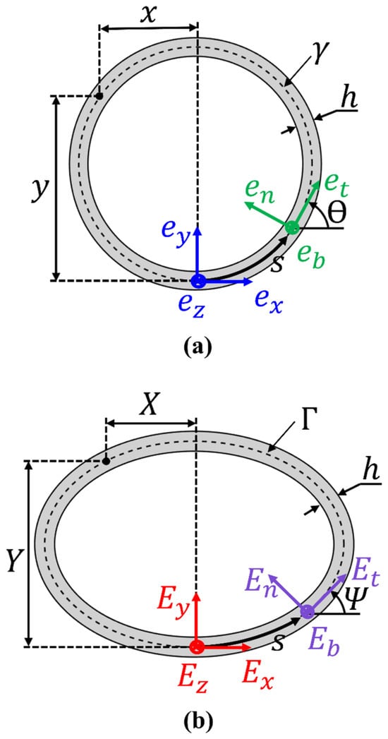
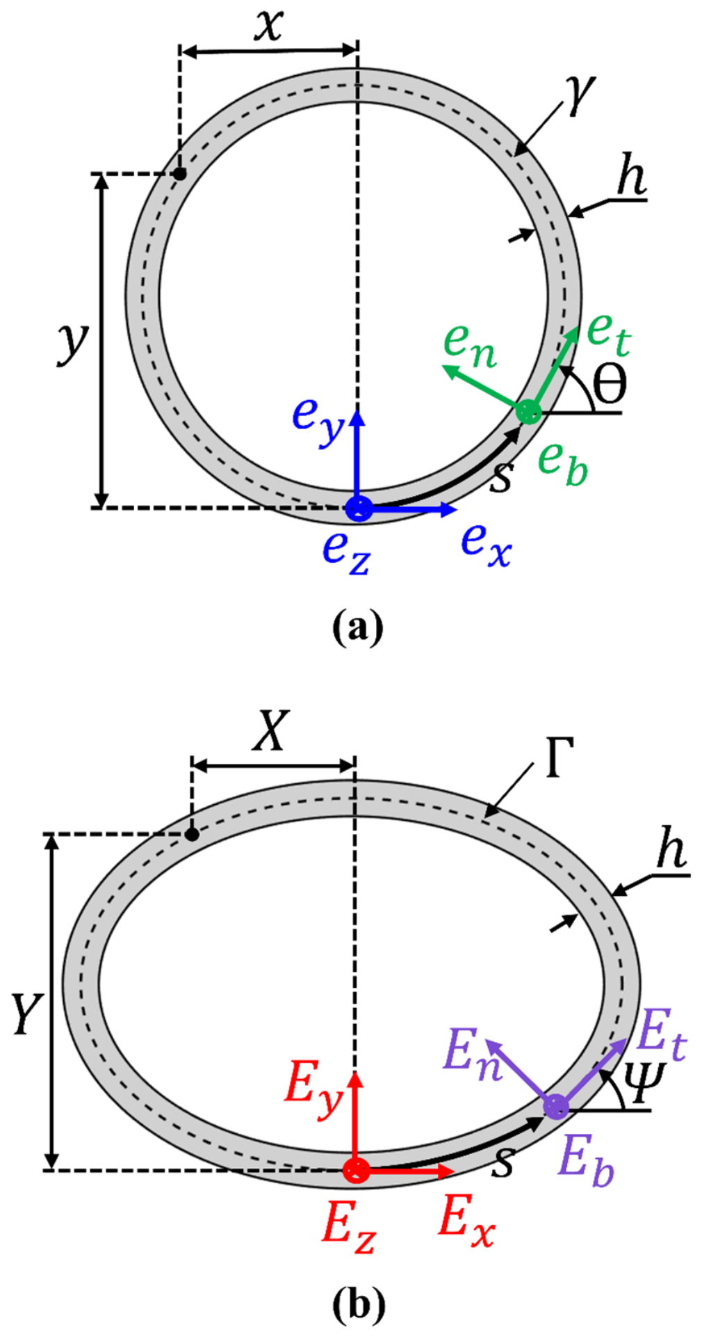
where ; is a dummy variable; and are the Young modulus and Poisson coefficient; is the thickness of the thin-walled structure; is the imposed curvature at the bottom material line of the tube; is the position of the points of the deformed middle line of the cross-section along the vertical axis, function of the curvilinear abscissa ; and are the angles of the tangent unit-vector of the cross-section centerline in the undeformed and deformed configuration, respectively; and is the length of the middle line γ of the undeformed cross-section. A geometrical representation of the previously defined variables is presented in Figure 2.
Figure 2.
(a) Undeformed and (b) deformed configuration of the tube’s cross-section with the respectively fixed and mobile frames .
In Equation (1), two energy contributions can be distinguished: The first is a beam-like term associated with bending of the member axis, evaluated with geometrically nonlinear kinematics and with the second moment of area computed on the current (warped) section. Equation (1) takes into account that the neutral axis position is evaluated on the current configuration to ensure that axis-bending energy reflects the actual evolving geometry rather than the undeformed one. The second is a shell-like term associated with in-plane ovalization (warping) of the section, whose stiffness term is the classical bending stiffness of thin shells.
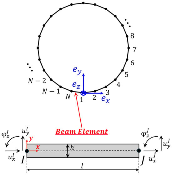
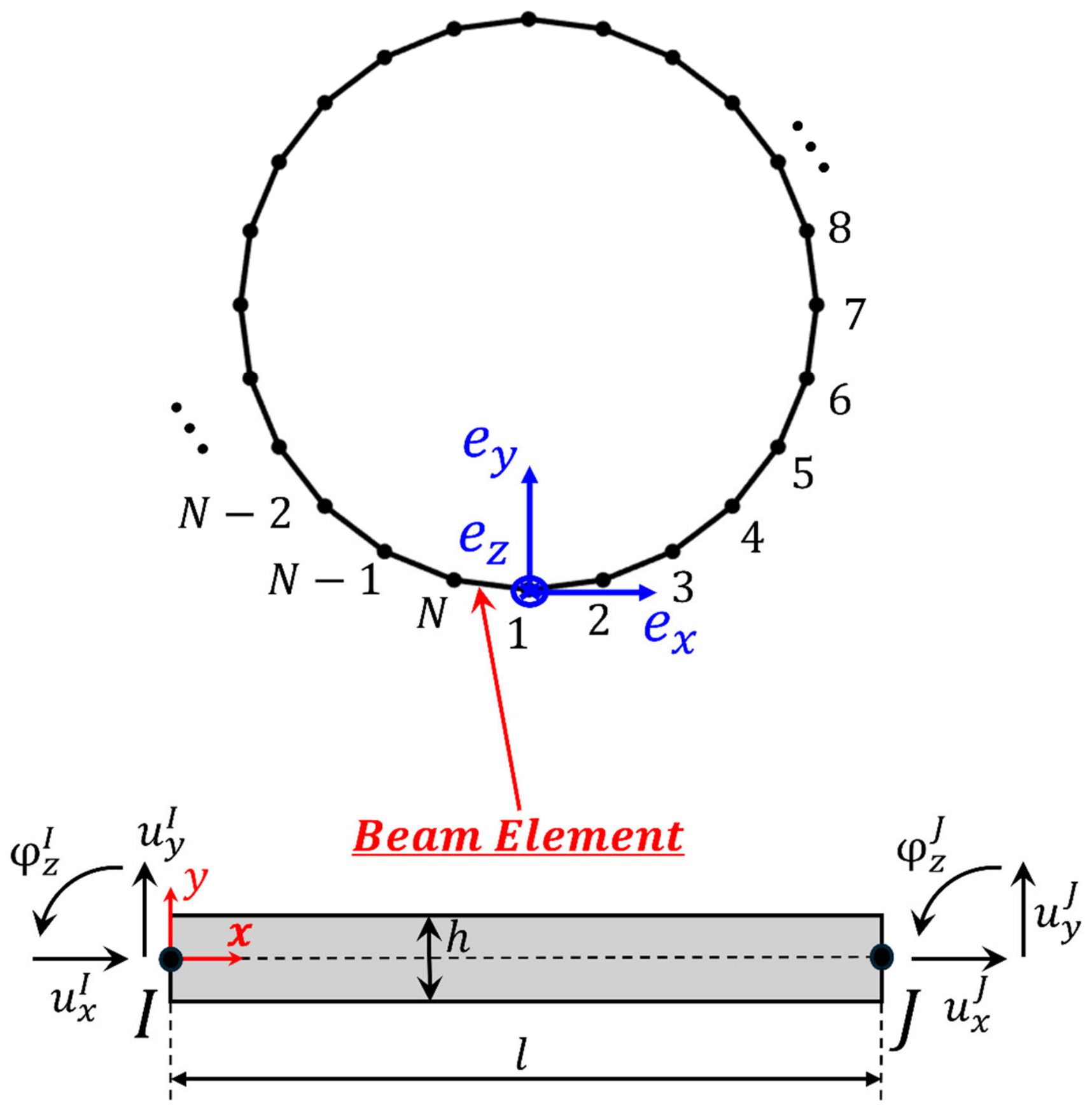
To determine the deformed configuration that makes Equation (1) stationary, a modal approach is adopted. Mode construction proceeds from a discrete model of the cross-section. Its mid-line is discretized with nodes using beam finite elements (Figure 3). The assembled stiffness matrix is used to solve the stiffness eigenproblem:
where is the identity matrix and , are the k-th eigenvalue and eigenvector respectively.
Figure 3.
Discretization of the tube cross-section into beam finite elements.
The resulting eigenvectors, ordered by increasing eigenvalue and in which the first three rigid-body modes are removed, form a compact basis of mechanically deformed patterns tailored to the specific cross-section. The number of extracted modes is far smaller than the total DOFs of the mesh, and the number of taken modes will be discussed in the results section. For the developments that follow, each eigenvector is partitioned into its DOFs components, translations along the global x- and y-axes and the rotation, yielding three vectors for each extracted eigenvector. To move from nodal discretized values to smooth fields along the mid-line, these vectors are interpolated with smoothing splines as functions of the curvilinear coordinate obtaining the analytical functions , which provides a differentiable description of position and curvature along the curvilinear coordinate and stabilizes the calculation of energetic derivatives.
The deformed cross-section is represented as the superposition of the taken modes (having excluded rigid modes), weighed by the modal amplitude coefficients , added to the undeformed nodal coordinates (Figure 2):
Therefore, the total potential energy in Equation (1), defined as the sum of the axis-bending and sectional-warping energy contributions, is made stationary with respect to the modal amplitudes
The use of the total potential energy and its stationarity with respect to a reduced set of generalized coordinates is consistent with standard variational energy methods in applied mechanics [40]. Using Equations (1) and (3) one obtains:
Consequently, the stationarity of the energy with respect to the modal amplitude coefficients yields a set of nonlinear governing equations written in analytical form. Alongside Equations (4) and (5), the result is fundamental to impose the inextensibility condition of the cross-section mid-line length. This constraint is enforced requiring that the length of the current reference line , during the evaluation of the modal weights , is equal to the reference length of the undeformed reference line :
where
For computational effortlessness, the constraint of Equation (6) is inserted directly into the following nonlinear system, which now becomes equations (Equations (4) and (6)):
where is a weighting coefficient used to penalize the constraint-equation error more heavily than the errors in the energy equations.
Equation (8) admits no closed-form solution and must be handled numerically. We employ a numerical strategy recently adopted by the authors also in [41,42,43] for problems of the same nature as Equation (8), by recasting Equation (8) as an optimization task. Specifically, we solve for the coefficients by minimizing the residual norm, i.e.,
Thanks to the convexity of Equation (9), any exact satisfaction of Equation (8) corresponds to a strong minimum of the objective function. A practical advantage of this reformulation is that it provides a built-in a posteriori check, since evaluating the residual of Equation (8) at the candidate solution from Equation (9) immediately indicates whether convergence has been reached. Therefore, the simple and robust stopping criterion is adopted, where is a small tolerance value. In this manner the unknown modal coefficients are found by an unconstrained optimization, without using auxiliary multipliers.
Once the system is solved, the modal coefficients give the warped section geometry for the prescribed curvature (Figure 1).
To follow how applied moment–curvature relationships develop and to enhance robustness near stiffness softening, the solution is advanced incrementally. Rather than imposing the target curvature in a single step, the curvature is increased through small substeps. At each i-th increment the converged solution from the previous substep is assumed as an initial state for the new solution, i.e., considering , and then perturbed with the newly computed modes. After convergence, all geometry-dependent quantities, i.e., interpolated mid-line, tangent rotation, neutral axis location, and sectional properties, are recomputed on the newly deformed section before proceeding to the next increment. This update-and-perturb loop allows to effortlessly follow the overall geometrical nonlinearity while keeping each incremental solve well-conditioned, allowing the progressive reduction in effective bending stiffness due the in-plane warping of the cross-section.
The corresponding applied bending moment to realize the imposed curvature is recovered a posteriori, once the deformed solution is known, by [30].
where and are the dimensionless bending moment and curvature, while the other variables with the symbol indicate the dimensionlessness with respect to the mid-line length.
By repeating the computation of Equation (10) for each applied substep curvature, the moment–curvature relationship in non-dimensional form is provided.
3. Applications of the Energetic-Modal Approach and Validation vs. FEA
This section discusses the results obtained with the energetic-modal formulation presented in Section 2 on two geometries, chosen to exercise different deformation mechanisms and loading-path features: a thin circular tube, representative of closed sections dominated by in-plane ovalization, and an open U-profile, where in-plane warping interacts more visibly. In both cases, the response is compared with shell FEA conducted under curvature-controlled loading.
The number of nodes and modes used to proceed is chosen based on the observation that increasing them leads to a monotonic convergence of the solution. In the first substep of the solution procedure a unit trial vector is applied to consider the same weight of the deformation modes. With this trial vector, Equation (9) is solved for the corresponding curvature value and the moment causing it is calculated.
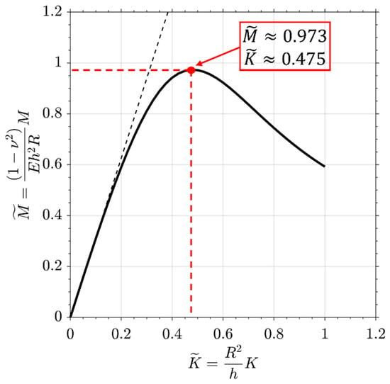
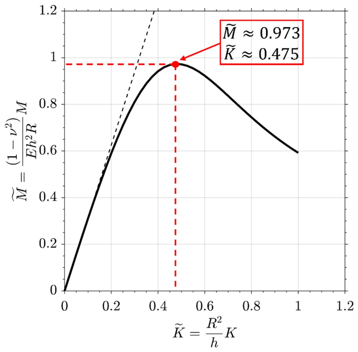
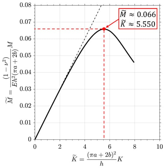
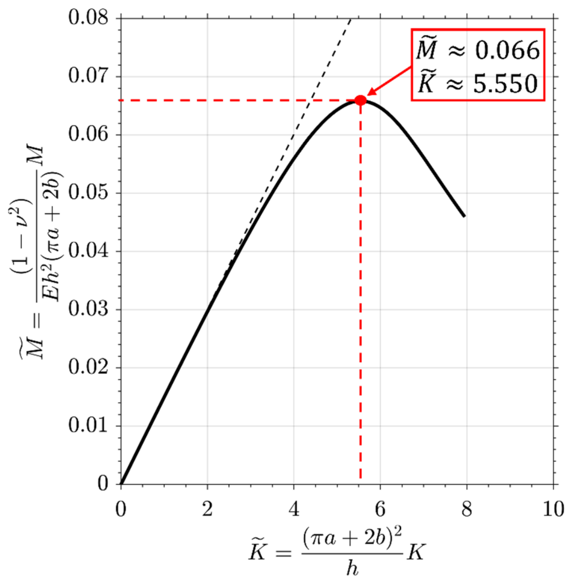
Proceeding incrementally in this manner, as described in Section 2 and using the first non-rigid seven modes, it is possible to derive the complete dimensionless moment–curvature relationship of Figure 4 which is valid for every pipe whatever thickness, radius and isotropic linear elastic material. For the circular case, this reduction is particularly meaningful because the elastic geometrically nonlinear problem collapses to a single curve. The well-known sequence, i.e., initial hardening, a peak under moment control, and a descending branch reachable only under curvature (or end-rotation) control, emerges naturally from the progressive ovalization that accompanies bending and it is captured by the proposed modal approach. Therefore, the resulting curve can be recognized as “universal” for circular pipes within the elastic regime and has been documented in prior shell-based studies [34,44].
Figure 4.
Dimensionless moment–curvature diagram for circular tubes.
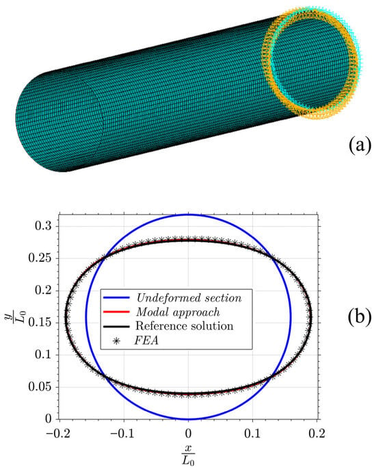
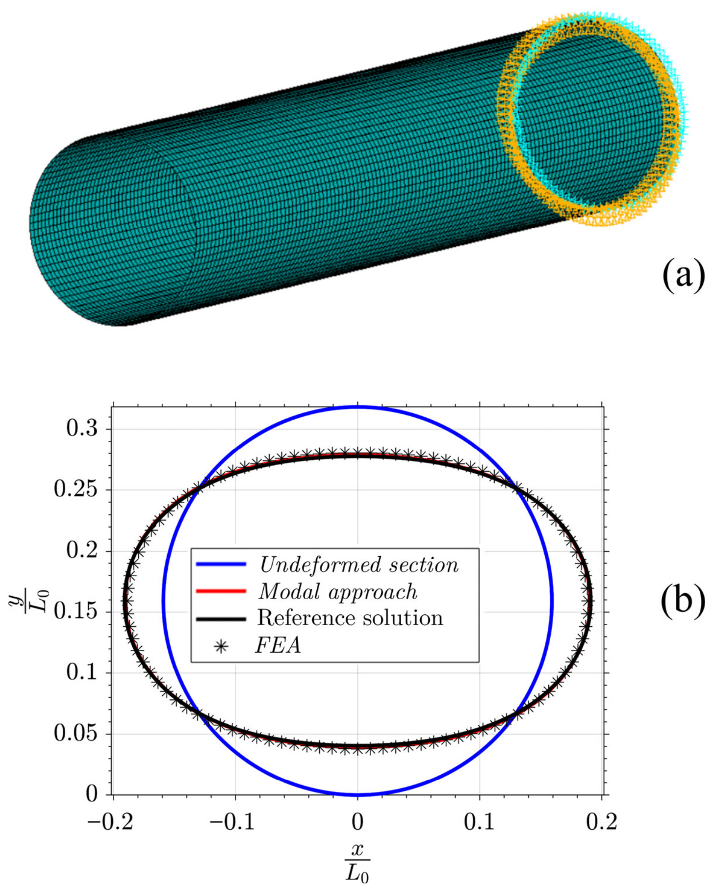
The above procedure is also applied to a specific pipe’s geometry with 37.5 mm radius, 0.4 mm thickness, considering material assumed linear, elastic and isotropic with a Young’s modulus and a Poisson’s coefficient . The results of the modal approach are verified through a geometric nonlinear FEA using 15,000 quadratic shell elements [45], with 96 elements along each section contour and 157 elements along the tube’s length, assumed equal to five times the diameter to simulate the behavior of a long tube. The FE model in Figure 5a was constrained at the end with boundary conditions imposed to allow the in-plane warping of the right end-section. The ovalized condition is reproduced by applying a rotation law to each cross-section of the pipe’s FE model such as to follow a circular arc with the prescribed curvature of , or in the dimensionless form of . The FEA involves a critical moment equal to , correspondent to , very close to the critical moment of obtained from the modal approach. The results of the modal approach are compared with both the FEA and the reference solution [30] in Figure 5b; the close agreement of the deformed sections demonstrates the consistency of the proposed method.
Figure 5.
(a) FE model; (b) comparison of the deformed cross-section obtained with the modal approach, the reference [30] and the FEA.
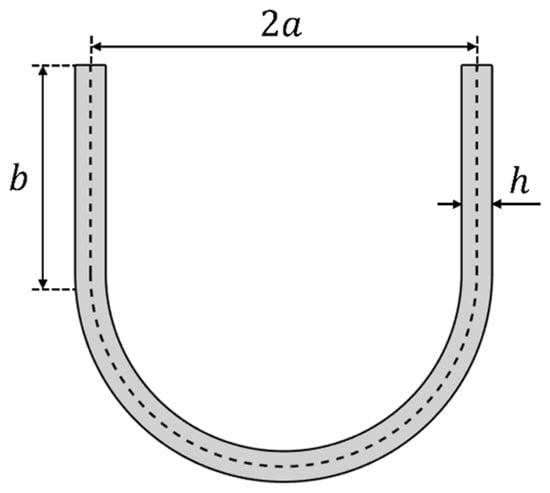
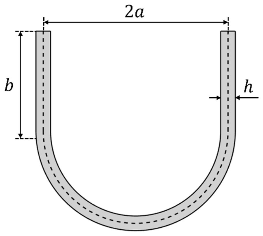
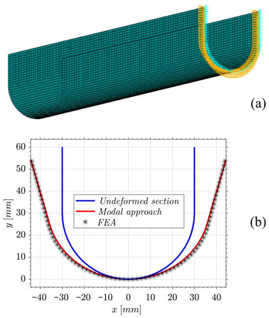
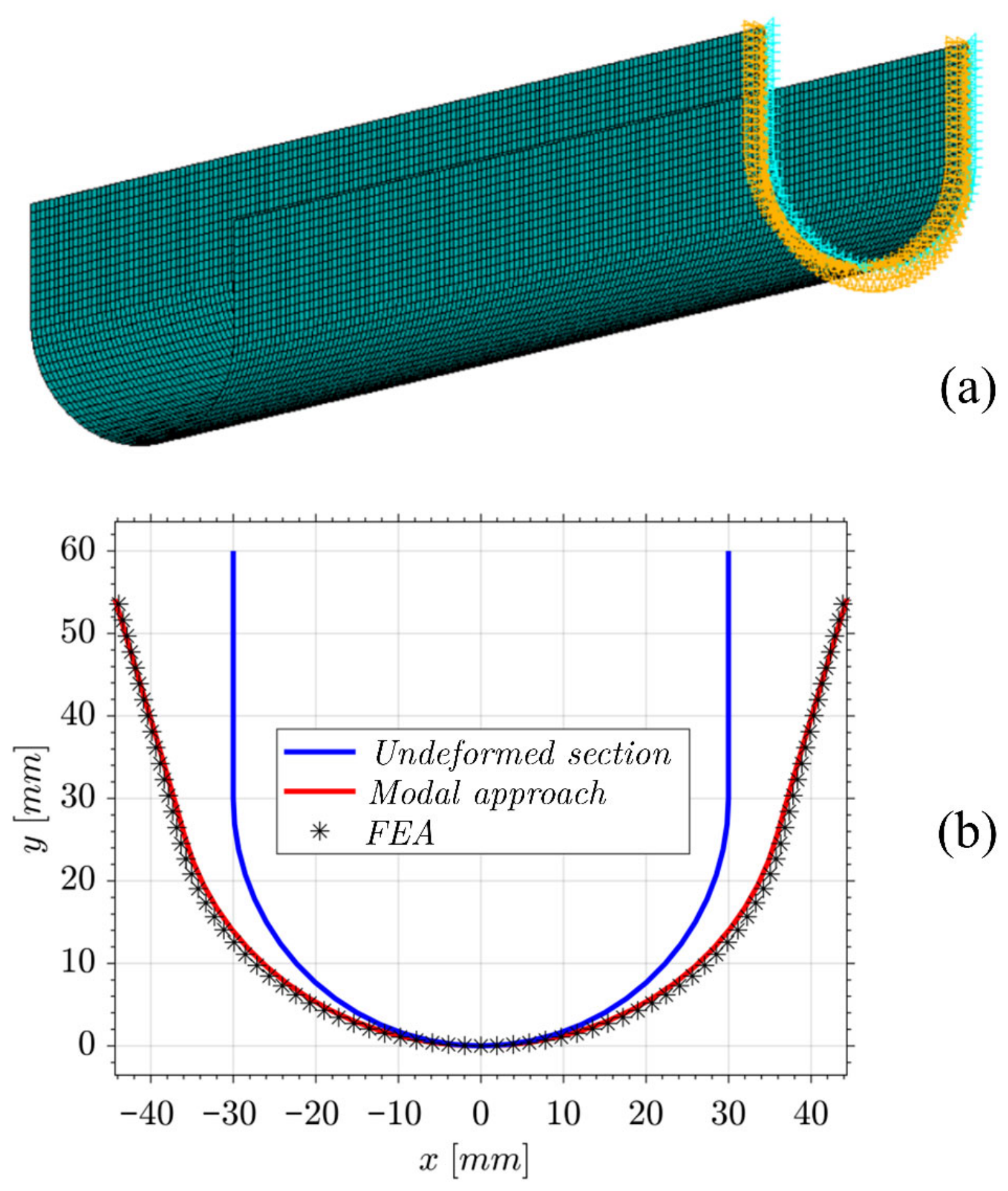
The second case considers a U-shaped profile with (Figure 6). Also for this section a small set of stiffness-derived modes, equal to seven, are sufficient. The dominant deformation mechanism in this case is the distortion of the flanges. This is a demanding test because open sections are more sensitive to the kinematic representation, yet the compact modal basis extracted from the sectional stiffness reproduces the correct in-plane warping without spurious oscillations or numerical artifacts. The dimensionless moment–curvature for this section is shown in Figure 7. Also in this case a comparison with the FEA is performed. The FE shell counterpart mirrors the closed-tube discretization strategy, with a mesh of 12,000 shell elements (Figure 8a), eighty elements around the perimeter and 150 along the span and a total length about five times the characteristic section size to suppress end effects. Figure 8b shows that the modal solution and the FE shell deformed shape overlay with good correspondence, confirming that a small modal set is adequate to capture the governing mechanics of open sections under finite bending with the same fidelity observed for the circular tube and at substantially lower computational cost.
Figure 6.
Geometry nomenclature of the U-section.
Figure 7.
Dimensionless moment–curvature diagram of the U-section with and .
Figure 8.
(a) FE model; (b) comparison of the deformed U cross-section obtained with the modal approach and FEA.
4. Conclusions
This paper introduces a modal, energy-based, framework to predict cross-section deformation of thin-walled tubes and beams of whatever sectional shape subjected to finite pure bending.
We show that the geometrically exact shell problem in pure bending can be treated more directly and with far less computational effort for any tubular cross-section by representing the sectional kinematics with a set of modes. Instead of tackling the nonlinear ODE system with BVP directly, a beam-element model of the section furnishes a concise eigenmode set whose coefficients act as generalized coordinates in the total potential energy.
The deformation modes are constructed by discretizing the cross-section mid-line with beam elements and extracting the associated eigenvectors excluding rigid-body motions. These vectors form a mechanically meaningful basis tailored to the given section.
The resulting energy minimization yields a set of nonlinear governing equations in analytical form whose solution, obtained via an optimization algorithm, directly returns the modal weights. To ensure the robustness of the numerical solution, the problem is solved incrementally in substeps; the target curvature is applied in small increases, and at each increment the previous solution serves as the initial state, which is then perturbed and updated through the new modes until convergence. With this strategy the model reproduces the progressive stiffness decreasing and non-monotone moment–curvature response characteristic of finite pure bending in dimensionless form. For closed sections the response is dominated by in-plane ovalization with a Brazier-type softening, whereas for open sections the in-plane warping causes distortion of flanges and governs the nonlinear evolution of stiffness.
The approach remains effective with a small set of modes and its energetic consistency intrinsically couples the beam-like behavior with the cross-sectional evolution, updating effective global bending stiffness as the deformation grows.
The proposed method has been validated for both open and closed sections against benchmark results from the literature and FEA using shell elements, showing close agreement in cross-sectional deformation pattern.
Author Contributions
Conceptualization, C.I. and P.S.; methodology, C.I. and D.M.; software, C.I. and D.M.; validation, C.I., D.M. and P.S.; formal analysis, C.I. and D.M.; investigation, C.I., D.M. and P.S.; resources, P.S.; data curation, C.I. and D.M.; writing—original draft preparation, C.I.; writing—review and editing, C.I. and D.M.; visualization, C.I. and D.M.; supervision, C.I.; project administration, C.I. and P.S. All authors have read and agreed to the published version of the manuscript.
Funding
This research received no external funding.
Institutional Review Board Statement
Not applicable.
Informed Consent Statement
Not applicable.
Data Availability Statement
Data are contained within the article.
Conflicts of Interest
The authors declare no conflicts of interest.
References
- Nayyar, M.L. Piping Handbook, 7th ed.; McGraw-Hill Education: New York, NY, USA, 1999. [Google Scholar]
- McKetta, J.J. Piping Design Handbook; CRC Press: Boca Raton, FL, USA, 2019. [Google Scholar]
- Bai, Y.; Bai, Q. Subsea Pipeline Integrity and Risk Management; Gulf Professional Publishing: Cambridge, MA, USA, 2014. [Google Scholar]
- Guo, B.; Song, S.; Ghalambor, A.; Lin, T. Offshore Pipelines Design, Installation, and Maintenance, 2nd ed.; Gulf Professional Publishing: Cambridge, MA, USA, 2013. [Google Scholar]
- Brazier, L.G. On the flexure of thin tubular shells and other “thin” sections. Proc. R. Soc. Lond. 1927, 116, 104–114. [Google Scholar] [CrossRef] [Scilit]
- Mazor, D.; Rand, O. The influence of the in-plane warping on the behavior of thin-walled beams. Thin-Walled Struct. 2000, 37, 363–390. [Google Scholar] [CrossRef] [Scilit]
- Luongo, A.; Zulli, D.; Scognamiglio, I. The Brazier effect for elastic pipe beams with foam cores. Thin-Walled Struct. 2018, 124, 72–80. [Google Scholar] [CrossRef] [Scilit]
- Iandiorio, C.; Salvini, P. Bending Ovalization of Thin-Walled Circular Tubes. Adv. Sci. Technol. 2024, 144, 135–150. [Google Scholar] [CrossRef] [Scilit]
- Vlasov, V.Z. Thin-Walled Elastic Beams, 2nd ed.; Israel Program for Scientific Translations: Jerusalem, Israel, 1961. [Google Scholar]
- Gjelsvik, A. The Theory of Thin Walled Bars; Wiley: New York, NY, USA, 1981. [Google Scholar]
- Murray, N.W. Introduction to the Theory of Thin-Walled Structures; Oxford University Press: Oxford, UK, 1984. [Google Scholar]
- Timoshenko, S.P. Strength of Materials (Part I & II); Van Nostrand Company Publisher: Princeton, NJ, USA, 1940. [Google Scholar]
- Öchsner, A. Classical Beam Theories of Structural Mechanics; Springer: Cham, Switzerland, 2021. [Google Scholar]
- Iandiorio, C.; Salvini, P. An Engineering Theory of thick Curved Beams loaded in-plane and out-of-plane: 3D Stress Analysis. Eur. J. Mech.-A/Solids 2022, 92, 104484. [Google Scholar] [CrossRef] [Scilit]
- Reissner, E. On one-dimensional finite-strain beam theory: The plane problem. Z. Angew. Math. Phys. (ZAMP) 1972, 23, 795–804. [Google Scholar] [CrossRef] [Scilit]
- Simo, J.C. A finite strain beam formulation. The three-dimensional dynamic problem. Part I. Comput. Methods Appl. Mech. Eng. 1985, 49, 55–70. [Google Scholar] [CrossRef] [Scilit]
- Batista, M. Analytical treatment of equilibrium configurations of cantilever under terminal loads using Jacobi elliptical functions. Int. J. Solids Struct. 2014, 51, 467–484. [Google Scholar] [CrossRef] [Scilit]
- Iandiorio, C.; Salvini, P. Large displacements of slender beams in plane: Analytical solution by means of a new hypergeometric function. Int. J. Solids Struct. 2020, 185–186, 467–484. [Google Scholar] [CrossRef] [Scilit]
- Iandiorio, C.; Salvini, P. Heavy Elastica soil-supported with lifting load and bending moment applied to an end: A new analytical approach for very large displacements and experimental validation. Int. J. Solids Struct. 2020, 206, 153–169. [Google Scholar] [CrossRef] [Scilit]
- Iandiorio, C.; Salvini, P. Inflectional Heavy Elastica with Unilateral Contact constraint: Analytical Solution through the Curvilinear Abscissa Mapping approximation. Int. J. Solids Struct. 2022, 234–235, 111258. [Google Scholar] [CrossRef] [Scilit]
- Hibbitt, H.D.; Becker, E.B.; Taylor, L.M. Nonlinear analysis of some slender pipelines. Comp. Meth. Appl. Mech. Eng. 1979, 18, 203–225. [Google Scholar] [CrossRef] [Scilit]
- Ansari, K.A. Nonlinear stress analysis of offshore pipelines during pickup operations. Comp. Struct. 1984, 8, 357–363. [Google Scholar] [CrossRef] [Scilit]
- Ngiam, P.C.A.; Jo, C.H. Intrinsic Coordinate Elements for Large Deflections of Offshore Pipelines. Int. J. Offshore Polar Eng. 2000, 10, 149–157. [Google Scholar]
- Mittelstedt, C. Generalized beam theory for the analysis of thin-walled structures—A state-of-the-art survey. Thin-Walled Struct. 2024, 200, 111849. [Google Scholar] [CrossRef] [Scilit]
- Schardt, R. Generalised Beam Theory—An adequate method for coupled stability problems. Thin-Walled Struct. 1994, 19, 161–180. [Google Scholar] [CrossRef] [Scilit]
- Silvestre, N.; Camotim, D. Second-order generalised beam theory for arbitrary orthotropic materials. Thin-Walled Struct. 2002, 40, 791–820. [Google Scholar] [CrossRef] [Scilit]
- Bianco, M.J.; Habtemariam, A.K.; Könke, C.; Zabel, V. Analysis of warping and distortion transmission in mixed shell–GBT (generalized beam theory) models. Int. J. Adv. Struct. Eng. 2019, 11, 109–126. [Google Scholar] [CrossRef] [Scilit]
- Synge, J.L.; Chien, W.Z. The intrinsic theory of elastic shells and plates. In Applied Mechanics, Theodore von Karman Anniversary Volume; California Institute of Technology: Pasadena, CA, USA, 1941; pp. 103–120. [Google Scholar]
- Chien, W.Z. The Intrinsic Theory of Thin Shells and Plates: Part I.—General Theory. Q. Appl. Math. 1994, 1, 297–327. [Google Scholar]
- Chien, W.Z. The Intrinsic Theory of Thin Shells and Plates: Part II.—Applications to thin Plates. Q. Appl. Math. 1994, 2, 43–59. [Google Scholar]
- Chien, W.Z. The Intrinsic Theory of Thin Shells and Plates: Part III.—Applications to thin Shells. Q. Appl. Math. 1994, 2, 120–135. [Google Scholar]
- Reissner, E. On finite pure bending of cylindrical tubes. Österr. Ing. Arch. 1961, 15, 165–172. [Google Scholar]
- Reissner, E.; Weinitschke, H.J. Finite pure bending of circular cylindrical tubular shells. Q. Appl. Math. 1963, 20, 305–319. [Google Scholar] [CrossRef] [Scilit]
- Reissner, E. On Finite pure Bending of Curved Tubular shells. Int. J. Sol. Struc. 1981, 17, 839–844. [Google Scholar] [CrossRef] [Scilit]
- Iandiorio, C.; Salvini, P. A geometrically nonlinear shell theory for thin-walled tubes and beams subjected to large displacements and cross-section deformation. Thin-Walled Struct. 2025, 216, 113583. [Google Scholar] [CrossRef] [Scilit]
- Calladine, C.R. Theory of Shell Structures; Cambridge University Press: Cambridge, UK, 1983. [Google Scholar]
- Flügge, W. Stresses in Shells, 2nd ed.; Springer: Berlin/Heidelberg, Germany, 1973. [Google Scholar]
- Koiter, W.T. On the nonlinear theory of thin elastic shells. Proc. Kon. Ned. Akad. Wet. 1966, B69, 1–54. [Google Scholar]
- Libai, A.; Simmonds, J.G. The Nonlinear Theory of Elastic Shells, 2nd ed.; Cambridge University Press: Cambridge, UK, 1998. [Google Scholar]
- Reddy, J.N. Energy Principles and Variational Methods in Applied Mechanics, 2nd ed.; John Wiley & Sons: New York, NY, USA, 2002. [Google Scholar]
- Iandiorio, C.; Milani, D.; Salvini, P. Optimal Uniform Strength Design of Frame and Lattice Structures. Comput. Struct. 2024, 301, 107430. [Google Scholar] [CrossRef] [Scilit]
- Iandiorio, C.; Cirelli, M.; Salvini, P.; Valentini, P.P. Elasto-Kinematics and second-order pseudo-rigid model of cross-axis flexure hinges. Mech. Mach. Theory 2025, 205, 105894. [Google Scholar] [CrossRef] [Scilit]
- Iandiorio, C.; Serenella, R.; Salvini, P. A Combined Approach of Experimental Testing and Inverse FE Modelling for Determining Homogenized Elastic Properties of Membranes and Plates. Eng. Proc. 2025, 85, 27. [Google Scholar] [CrossRef] [Scilit]
- Karamanos, S.A. Bending instabilities of elastic tubes. Int. J. Solids Struct. 2002, 39, 2059–2085. [Google Scholar] [CrossRef] [Scilit]
- Chapelle, D.; Bathe, K.-J. The Finite Element Analysis of Shells—Fundamentals, 2nd ed.; Springer: Berlin/Heidelberg, Germany, 2011. [Google Scholar] [CrossRef] [Scilit]
Disclaimer/Publisher’s Note: The statements, opinions and data contained in all publications are solely those of the individual author(s) and contributor(s) and not of MDPI and/or the editor(s). MDPI and/or the editor(s) disclaim responsibility for any injury to people or property resulting from any ideas, methods, instructions or products referred to in the content. |
© 2026 by the authors. Licensee MDPI, Basel, Switzerland. This article is an open access article distributed under the terms and conditions of the Creative Commons Attribution (CC BY) license.