


Abstract
This paper introduces an innovative radar-based navigation approach designed to address precision navigation challenges for Vertical Take-Off and Landing (VTOL) platforms. The key innovation is a unique extension of radar altimeter functionality when used with ground navigation beacons realized by Radio Frequency (RF) repeaters. The proposed solution is intended to support helicopter and Advanced Air Mobility (AAM) autonomous operations.
1. Introduction
Navigation is one of the key enablers for autonomous air vehicle operations as part of Advanced Air Mobility (AAM). The most critical phases of Vertical Take-Off and Landing (VTOL) autonomous flight, especially in terms of navigation accuracy and integrity requirements, are the approach and landing phases in complex/urban terrain surrounding highly constrained landing sites. Navigation solutions for these phases assume hybridization of various sensors and systems to create a solution that meets stringent navigation performance and integrity requirements. Current solutions are usually based on Inertial Navigation Systems (INS), Global Navigation Satellite Systems (GNSS), barometers, and radar altimeters to determine horizontal and vertical positions. Nowadays, the challenge is to satisfy the navigation requirements in GNSS-denied conditions. Various alternative navigation aiding systems can be used to complement GNSS such as Vision-based systems (EO/IR cameras), Lidar-based systems, Radar-based systems (Radar Altimeters or Imaging Radar), Marker-based systems, or RF beacon-based systems. One of many radar-based approaches is to extend the capability of the radar altimeter to provide not only the 1-dimensional vertical measurements but full 3-dimensional position measurements. This can be achieved with the help of dedicated ground/surface-based beacons at known positions, using the multilateration method and advanced detection algorithms. The beacons can be either passive (such as corner reflectors) or active (e.g., RF repeaters).
The utilization of passive radar reflectors has been considered to support approach and landing operations in many works; see [1], [2] or [3]. However, many challenges have to be overcome to satisfy navigation requirements. For example, proper arrangement of reflectors is not a trivial task, especially for VTOL operations. The reflectors need to be installed both close to the center of the helipad’s or vertiport’s landing site due to the limited beamwidth of the radar altimeter and installed at various heights above the surface (to provide different ranges other than the landing surface), which constitutes unwanted obstacles from an operational perspective. It is also difficult to distinguish between different reflectors that fall into the same measurement range bin of the radar. Even when the radar has the capability to provide accurate Angle of Arrival (AOA) measurements (e.g., using monopulse or multiple-input multiple-output (MIMO) techniques), the sidelobe and multipath antenna effects can lead to outlier detections and spurious measurements. In addition, it is difficult to reliably identify each (passive) reflector with the corresponding radar detection, which enables a high-integrity navigation solution. For these reasons, passive reflectors and the resulting radar-based navigation system for VTOL approach and landing phases likely do not satisfy accuracy and integrity requirements.
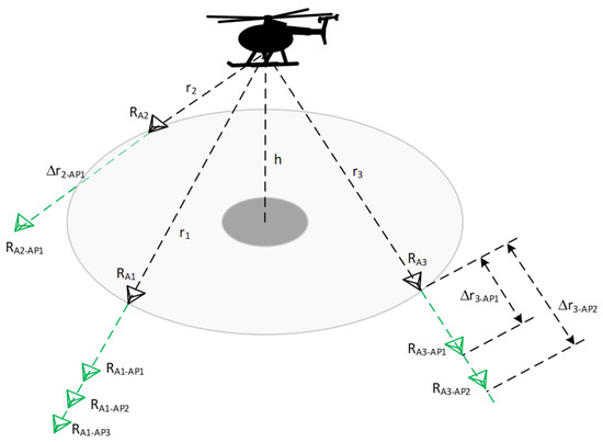
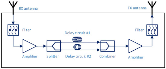
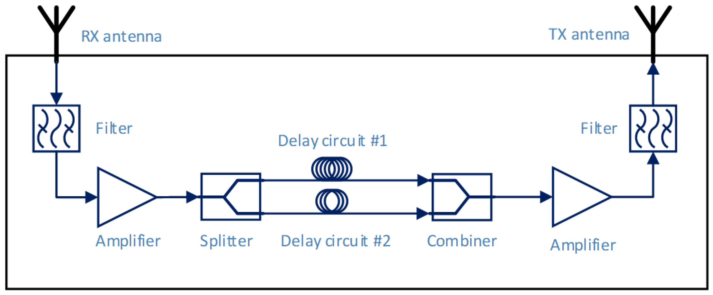
This paper presents a novel concept utilizing onboard radar altimeters and RF repeaters on the landing surface [4]. In contrast to passive reflector that just reflects the incoming radar signal and creates one echo, RF repeater can modify and retransmit the incoming radar signal and create a unique pattern of echoes. The signal modification helps to overcome the issues with reflector’s installation (eliminates the need to mount reflectors at different heights), detection, and identification. The signal modifications include signal amplification, delay, time extension, and even transmission of multiple copies of the received radar signals, wherein each copy of the retransmitted signal might be modified differently. For example, the received signal might be amplified and propagated through two or more different delay circuits. These signals are further denoted as artificial echoes. Signals from two or more delay circuits are combined together and transmitted back towards the onboard radar. As a result, the radar altimeter receives the reflected signal from the surface but also two or more additional modulated artificial echoes as radar reflections. The onboard radar altimeter processing unit determines detections corresponding to the surface (as performed by conventional radar altimeter) and detections corresponding to the artificial echoes. A similar principle of multitarget detection by radar sensor was presented in ref. [3] and multitarget detection by radar altimeter was presented in ref. [5]. A different, unique, set of artificial echoes might be used for each repeater and landing zone to enable detection and unique identification of individual repeaters and landing zones.
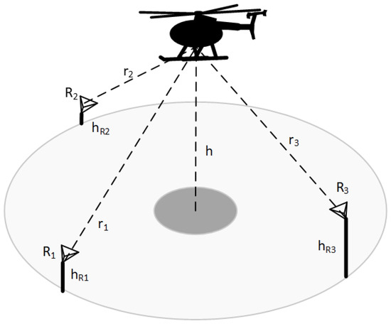
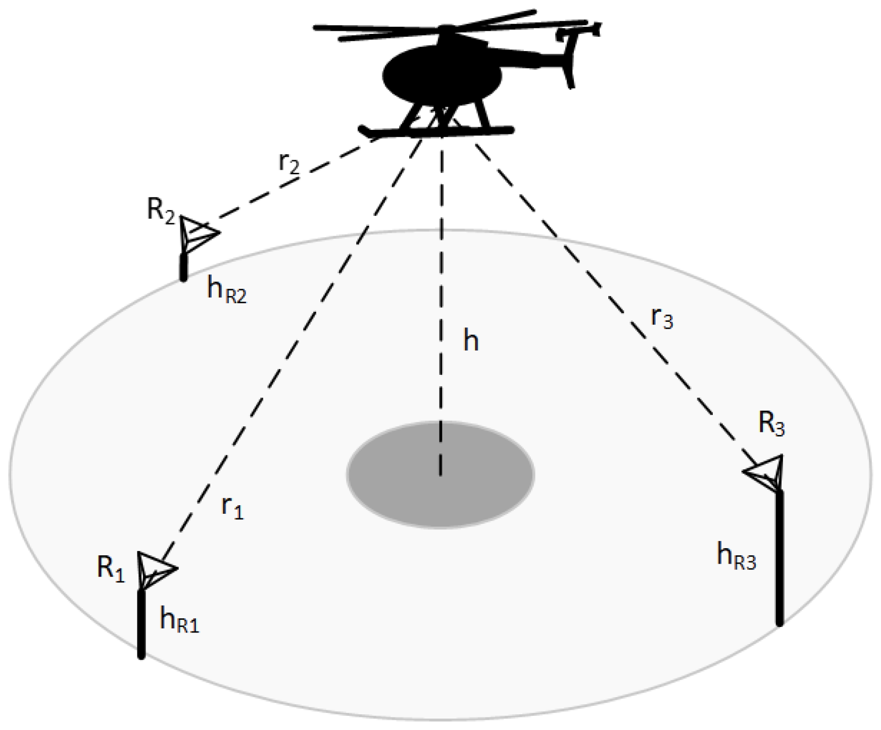
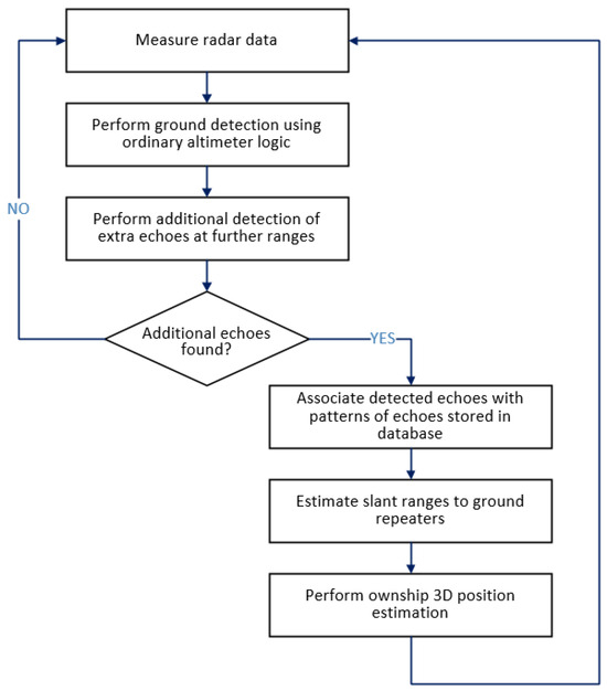
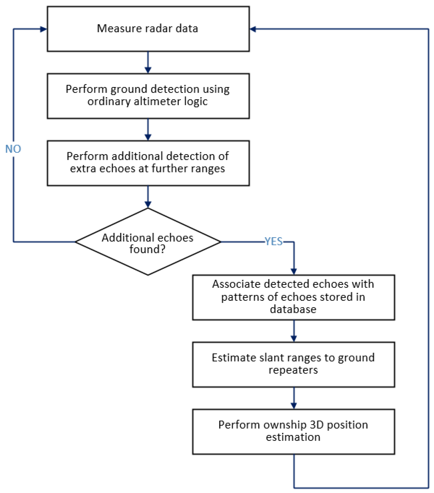
An onboard database with a list of repeaters, their coordinates, and patterns of echoes is required to enable the identification of repeaters and the computation of a navigation solution. After the repeater is identified, a slant range between the radar antenna and the repeater might be accurately measured. If three or more ranges are measured at an epoch, then the vehicle’s position can be estimated using well-known multilateration methods in various navigation frames; one such frame is the local-level frame where the repeater positions are given by the onboard database.
This paper describes the novel radar altimeter, surface repeater navigation concept, and the results of Uncrewed Aircraft System (UAS) flight test experiments with the repeaters. The flight tests included three prototype repeaters with known positions relative to the landing zone.
3. Experimental Validation
An experimental validation was performed to prove the feasibility of the proposed radar altimeter active repeater-based navigation solution.
3.1. Setup
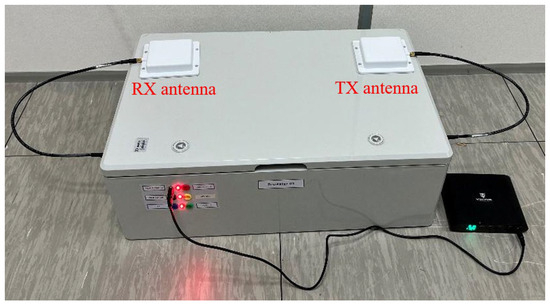
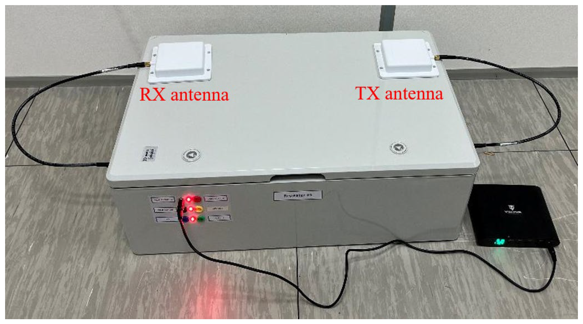
Honeywell built three prototype repeaters with different configurations. Figure 6 shows one of the ground repeater prototypes. The repeater configurations are as follows:
Figure 6.
RF repeater prototype.
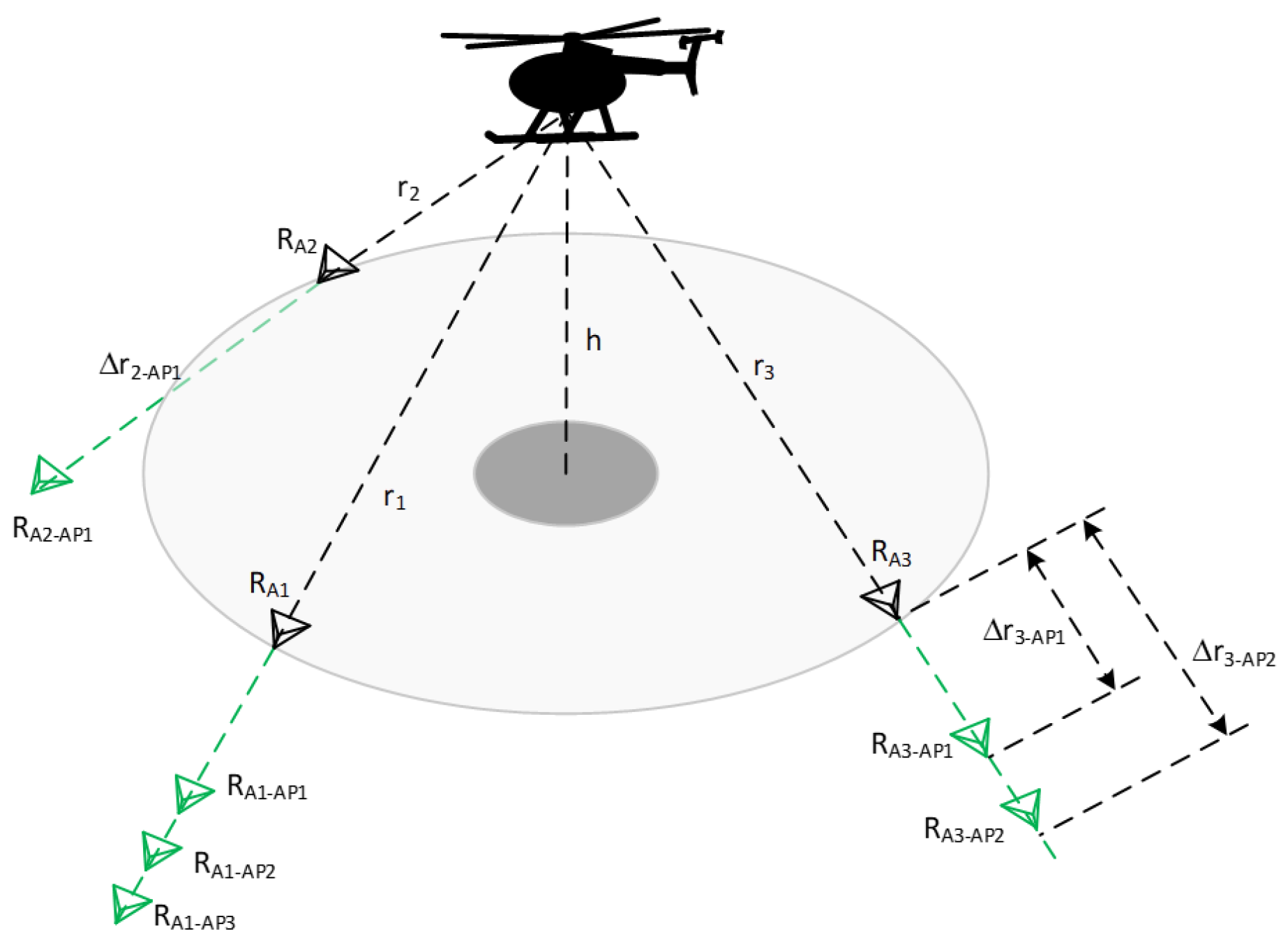
- Repeater #1: one artificial range echo with an artificial range shift (Δr1-AP1) equal to 43.0 m;
- Repeater #2: one artificial range echo with an artificial range shift (Δr2-AP1) equal to 65.5 m;
- Repeater #3: two artificial range echoes with artificial range shifts (Δr3-AP1 and Δr3-AP2) equal to 90.0 m and 95.0 m.
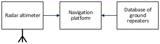
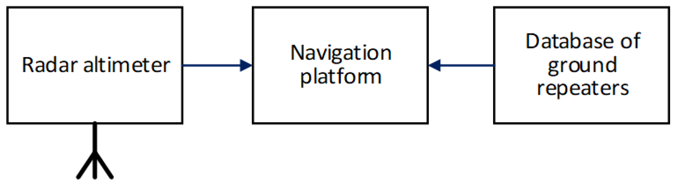
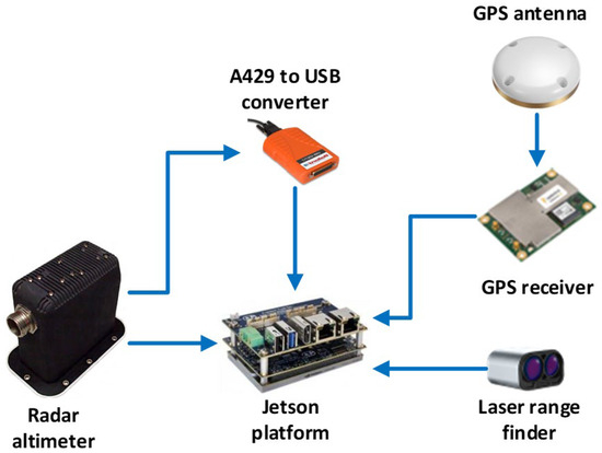
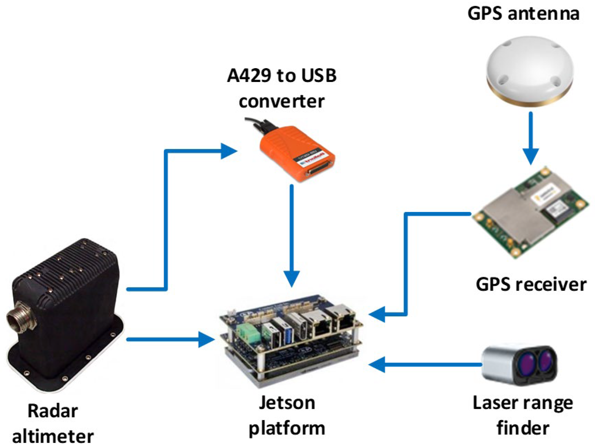
The onboard components of the radar altimeter active beacon-based navigation system used for experimental validation is shown in Figure 7. Data from Honeywell’s Single Antenna Radar Altimeter (SARA; ref. [7]) were recorded using a Jetson platform. Data from a GPS receiver and a Laser Range Finder (LRF), both mounted on the UAS, were also recorded. Data analysis was performed offline after the data collection.
Figure 7.
Onboard components of the navigation system used for experimental validation.
3.2. Data Collection
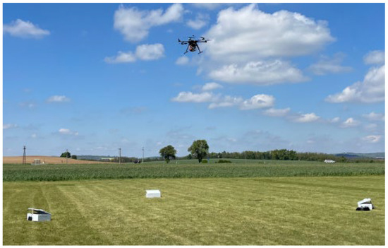
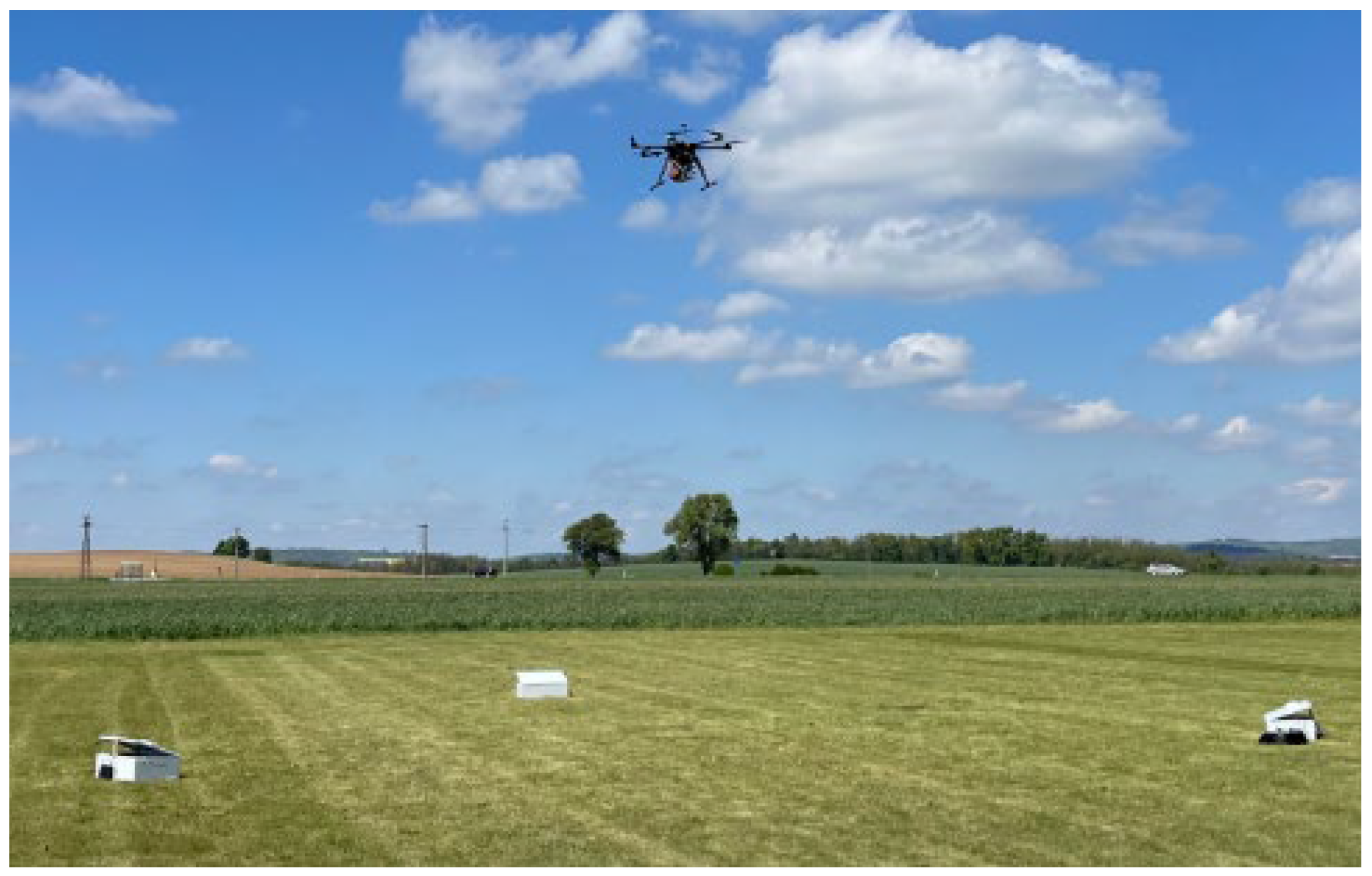
Data collection was performed to validate the feasibility and performance of the proposed navigation concept. The three repeater prototypes were placed around the landing site. A number of UAS maneuvers were performed, emulating both approach and landing scenarios. Figure 8 captures a UAS during a landing maneuver.
Figure 8.
Data collection using UAS.
3.3. Results
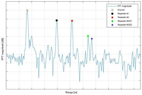
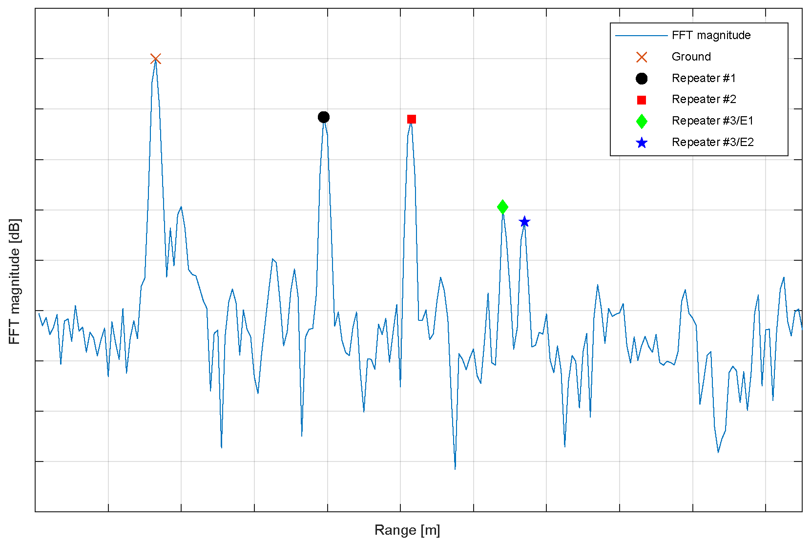
Data collected during the data collection exercise were analyzed offline. Figure 9 shows an illustrative example of radar altimeter data collected during the data collection. It visualizes signal magnitude as a function of range. Figure 9 shows a scenario when the UAS was 33 m above ground. The signal peak corresponding to the signal reflected from the ground is present in radar data at the corresponding range. All four artificial range echoes created by ground repeaters are present in radar signal at expected distances.
Figure 9.
Illustrative example of radar altimeter data.
Slant ranges (r1, r2, and r3) between ownship/platform and repeaters (active reflectors RA1, RA2, and RA3) were determined. Thereafter, the UAS 3D position by multilateration was estimated using the estimated slant ranges to the ground repeaters and their known positions.
4. Summary and Conclusions
The new VTOL Navigation Based on Radar Altimeter and Ground/Surface RF Repeaters was proposed, repeater prototypes were built, and experimental flight tests using UAS were performed.
Data collected during the flight tests were crucial for the assessment of the proposed navigation concept. The feasibility of the navigation concept was confirmed, and the initial performance analysis has shown promising results. It was also demonstrated that the proposed navigation concept is backward compatible with standard radar altimeters. The data collected will be used for further development.
Author Contributions
Conceptualization, P.K., T.B., J.R. and J.L.; methodology, T.B., M.D. and J.R.; software, J.R.; validation, P.K.; formal analysis, M.D.; investigation, M.D. and J.R.; resources, T.B. and J.L.; writing—original draft preparation, P.K.; writing—review and editing, P.K., T.B. and V.B.; visualization, P.K.; supervision, T.B. and V.B.; project administration, T.B. and V.B. All authors have read and agreed to the published version of the manuscript.
Funding
This research received no external funding.
Institutional Review Board Statement
Not applicable.
Informed Consent Statement
Not applicable.
Data Availability Statement
The data sets presented in this article are not publicly available because the data are under company policy restrictions. Further inquiries can be directed to the corresponding author.
Conflicts of Interest
Author Petr Kejik, Tomas Beda, Jan Reznicek, Michal Dobes, Jan Lukas and Vibhor Bageshwar were employed by the company Honeywell International.
Abbreviations
The following abbreviations are used in this manuscript:
| 3D | Three-Dimensional |
| AAM | Advanced Air Mobility |
| AOA | Angle Of Arrival |
| GNSS | Global Navigation Satellite System |
| GPS | Global Positioning System |
| INS | Inertial Navigation System |
| LRF | Laser Range Finder |
| MIMO | Multiple-Input Multiple-Output |
| RF | Radio Frequency |
| RX | Receiver |
| SARA | Single Antenna Radar Altimeter |
| TX | Transmitter |
| UAS | Uncrewed Aircraft System |
| VTOL | Vertical Take-Off and Landing |
References
- Korn, B.; Doehler, H.-U. Passive Landing Aids for Precision EVS Approach and Landing. Digital Avionics Systems Conference, 2003. DASC ‘03, October 2003. Available online: https://ieeexplore.ieee.org/document/5731161 (accessed on 5 March 2025). [CrossRef] [Scilit]
- Iizuka, T.; Sasatani, T.; Nakamura, T.; Kosaka, N.; Hisada, M.; Kawahara, Y. MilliSign: mmWave-Based Passive Signs for Guiding UAVs in Poor Visibility Conditions. In ACM MobiCom ‘23: Proceedings of the 29th Annual International Conference on Mobile Computing and Networking; Association for Computing Machinery: New York, NY, USA, 2023; pp. 1–15. [Google Scholar]
- Yasentsev, D.; Shevgunov, T.; Efimov, E.; Tatarskiy, B. Using Ground-Based Passive Reflectors for Improving UAV Landing. Drones 2021, 5, 137. [Google Scholar] [CrossRef] [Scilit]
- Beda, T.; Reznicek, J.; Kejik, P.; Lukas, J.; Bageshwar, V.L.; Ptacek, P. Landing Navigation Based on Radar Altimeter and Multi-Echoes RF Beacons. US Patent 2025/0004127 A1, 2 January 2025. Available online: https://patents.google.com/patent/US20250004127A1/en (accessed on 5 March 2025).
- Frick, S.; Vacanti, D.; Burlet, T. System and Method for Tracking a Sling Load and Terrain with a Radar Altimeters. US Patent 10,539,674 B2, 21 January 2020. Available online: https://patentimages.storage.googleapis.com/d2/53/be/a80d78493ab46f/US10539674.pdf (accessed on 5 March 2025).
- Bageshwar, V.L.; Ganapathy, A.; Venkataraman, V.; Srivastava, R. Systems and Methods for Extracting Surface Markers for Aircraft Navigation. US Patent 2025/0104419 A1, 27 March 2025. Available online: https://patents.google.com/patent/US20250104419A1/en (accessed on 23 March 2025).
- Honeywell. Single Antenna Radar Altimeter (SARA). Available online: https://aerospace.honeywell.com/us/en/products-and-services/products/cabin-and-cockpit/radios/radar-altimeters/single-antenna-radar-altimeter-sara (accessed on 25 March 2025).
Disclaimer/Publisher’s Note: The statements, opinions and data contained in all publications are solely those of the individual author(s) and contributor(s) and not of MDPI and/or the editor(s). MDPI and/or the editor(s) disclaim responsibility for any injury to people or property resulting from any ideas, methods, instructions or products referred to in the content. |
© 2026 by the authors. Licensee MDPI, Basel, Switzerland. This article is an open access article distributed under the terms and conditions of the Creative Commons Attribution (CC BY) license.