


Abstract
Based on ongoing experimental research, the present manuscript presents the effect of the slippage of a steel reinforcing bar due to corrosion on the chord rotation and deformation of corroded Reinforced Concrete members. The experimental results recorded that the increase in the corrosion level of the steel led to bond strength loss and relative slip between the steel and concrete, which was increased from 1.5 mm in non-corroded conditions to 3.5 mm even at low corrosion levels, up to a 5% steel mass loss. This slippage of corroded reinforcing bars from the anchorage leads to a proportional increase in terms of chord rotation due to pull out resulting in an additional increase in the displacement of the column’s top. In conclusion, the present study highlights the great importance of the contribution of the resulting slippage of a steel reinforcing bar due to corrosion in the calculation of the limit chord rotation (column–beam), a term which is of major importance in the assessment of the structural integrity of old RC structures, which was introduced as an adequacy requirement by both Eurocode 8-3 and the Greek Code of Structural Interventions (KAN.EPE).
1. Introduction
Reinforced Concrete (RC) has prevailed as the most popular construction and infrastructure material worldwide, as it is characterized by strong mechanical properties, low production costs, and easily available raw materials. However, the corrosion of steel reinforcements is recognized as a main degradation factor of the durability and serviceability of RC structures, since it leads mainly to the loss of bonding between steel and concrete and reduces the mechanical properties of steel reinforcement, affecting the entire structural behavior of RC members [1,2,3,4,5,6].
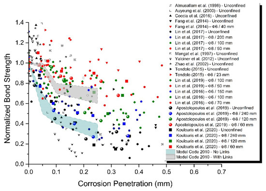
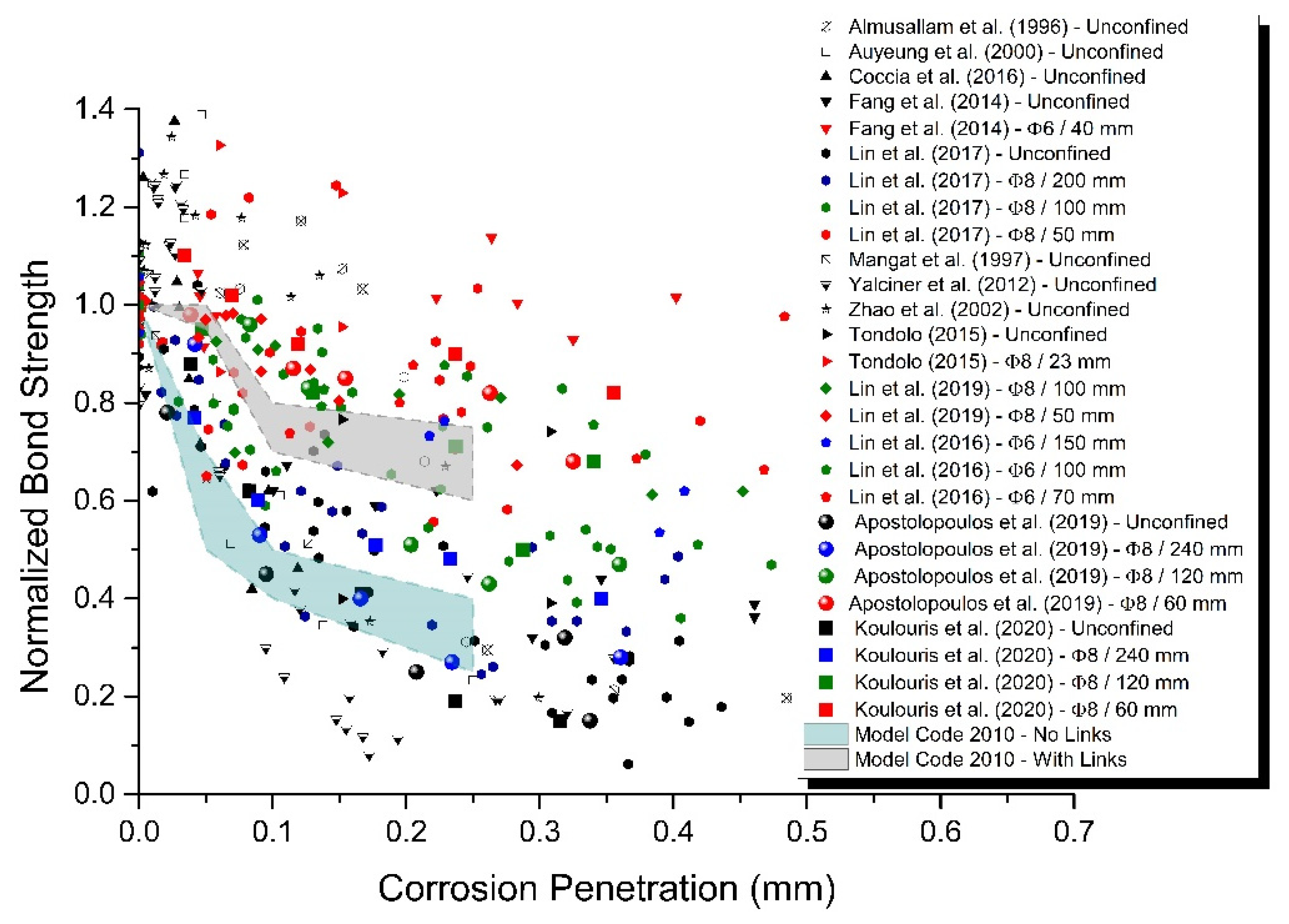
Various researchers [1,2] have indicated that the corrosion of steel reinforcement deteriorates the steel–concrete interface conditions, degrading the bond characteristics between both materials. The increasing volume of corrosion products (oxides) in relation to the initial material of steel results in the cracking and spalling of the concrete cover. Furthermore, the degraded interface conditions and the consequent reduction of ribs’ geometry due to corrosion affect the mechanical interlocking between steel and concrete and lead to an increase in relative slip between them and to a loss of bond strength (Figure 1).
Figure 1.
Reduction in bond strength due to steel corrosion as a function of corrosion penetration [1].
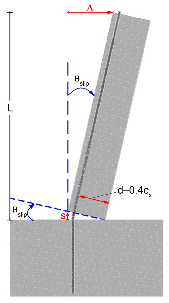
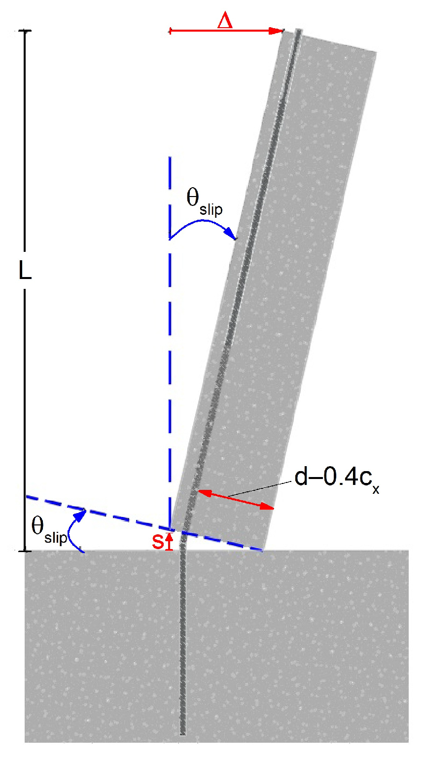
Generally, the slippage of a reinforcement (s) can be crucial in anchorage zones, since the pull out of a steel rebar has a direct effect on the deformation of RC members and, especially in the case of columns, leads to an increase in the chord rotation angle owing to slip (θslip) and displacement (Δ) at their top (Figure 2). The theoretical expression of chord rotation due to the slippage of steel bars is as follows in Equation (1) [6]:
Figure 2.
Increase in chord rotation angle (θslip) and displacement of the top (Δ) due to slippage of steel reinforcing bar in anchorage zone.
The slippage of a steel reinforcement and the consequent increase in chord rotation (θslip) is of great importance in the mechanical response of RC members, since the transfer of forces in an RC member occurs through three mechanisms, which for ductile members are considered to act in series: (a) the mechanism of force transfer through bending, (b) the mechanism of force transfer through shear, (c) the mechanism of transfer of longitudinal reinforcement stresses to the anchorage area. Consequently, the deformation of an RC member can be calculated as the sum of the deformation due to bending, θfl, due to shear, θsh and due to slippage of the reinforcement from its anchorage area, θslip.
The yielding chord rotation (θy) is a key parameter in assessing the structural capacity of existing RC members, particularly when subjected to seismic or other dynamic forces (EC8-3 or KAN.EPE) [7,8].
However, in the experimental data base, there are very few experiments on non-corroded RC members in which the chord rotation at yielding, due to the slip of the reinforcement from the anchorage area (θy,slip), has been measured separately. In the majority of experiments, the measurement of chord rotation due to slip is included in the chord rotation due to bending. Hence, the corresponding term of chord rotation due to slip, which is proposed by the technical regulations, is semi-empirical. It is noteworthy that in the case of corroded steel RC elements, there are no recorded measurements concerning the slip of steel reinforcements until now. As a result, there is a gap in the current scientific knowledge concerning the influence of corrosion on the mechanical behavior of corroded RC members and mainly in their rotational capacity.
For this reason, the present research studies the degradation of local bond properties due to steel corrosion, taking into account the confinement provided by stirrups and attempts to correlate the experimental results of the slippage of a corroded steel rebar with the rotational capacity (chord rotation) of corroded RC members due to the pull out of a steel reinforcement.
2. Materials and Methods
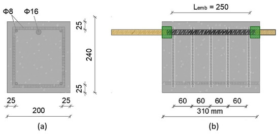
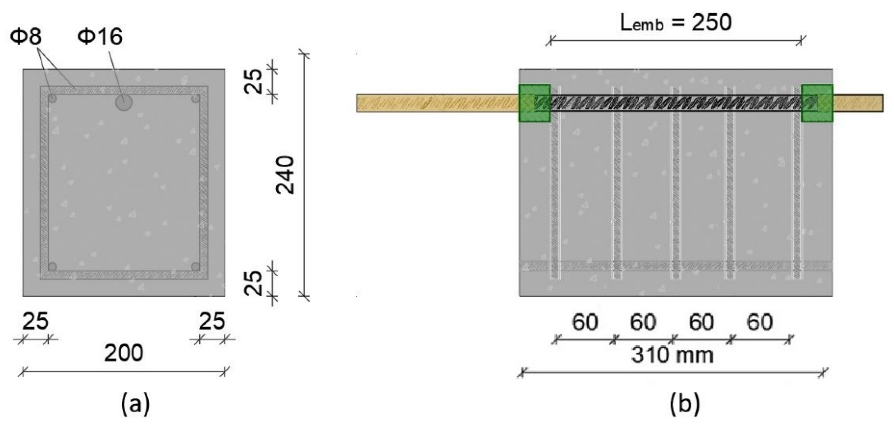
In order to investigate the bond mechanism between a corroded steel reinforcement and concrete, RC specimens were casted using the C20/25 concrete class and Tempcore B500c steel reinforcement grade, the geometry of which is illustrated in Figure 3. At this point, it is worth mentioning the fact that during the period between 1990 and 2010, the majority of the building stock located in coastal regions of the Mediterranean basin used the C20/25 concrete class, disregarding the provisions of standard EN 206 [9] for using higher concrete classes, i.e., C25/30 or C30/37. Hence, the choice of materials used in the abovementioned experimental study is in line with a typical old structure of that period. In particular, the main longitudinal reinforcement consisted of one semi-embedded rebar with a nominal diameter of 16 mm and the transverse reinforcement consisted of rebars with nominal diameters of 8 mm placed per 60 mm, i.e., Φ8/60 mm. Furthermore, the concrete cover was equal to 40 mm. In order to limit the corrosion damage only to the main rebar of RC specimens, all stirrups were protected with a special anti-corrosive coating (epoxy resin) and a 250 mm section of rebar was set to be exposed to corrosion and the rest was protected with a wax layer. Hence, the embedded length of the rebar in concrete, which was tested in pull out tests, was equal to 250 mm.
Figure 3.
Geometry of the RC specimens. Cross-section of specimen (a); side view of specimen (b).
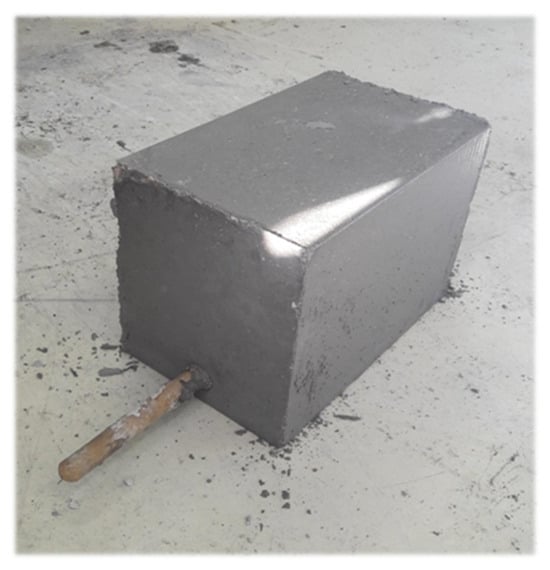
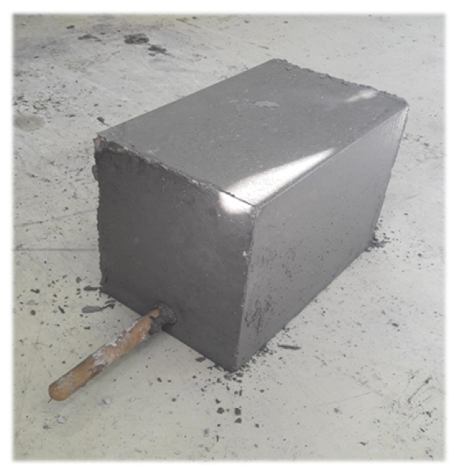
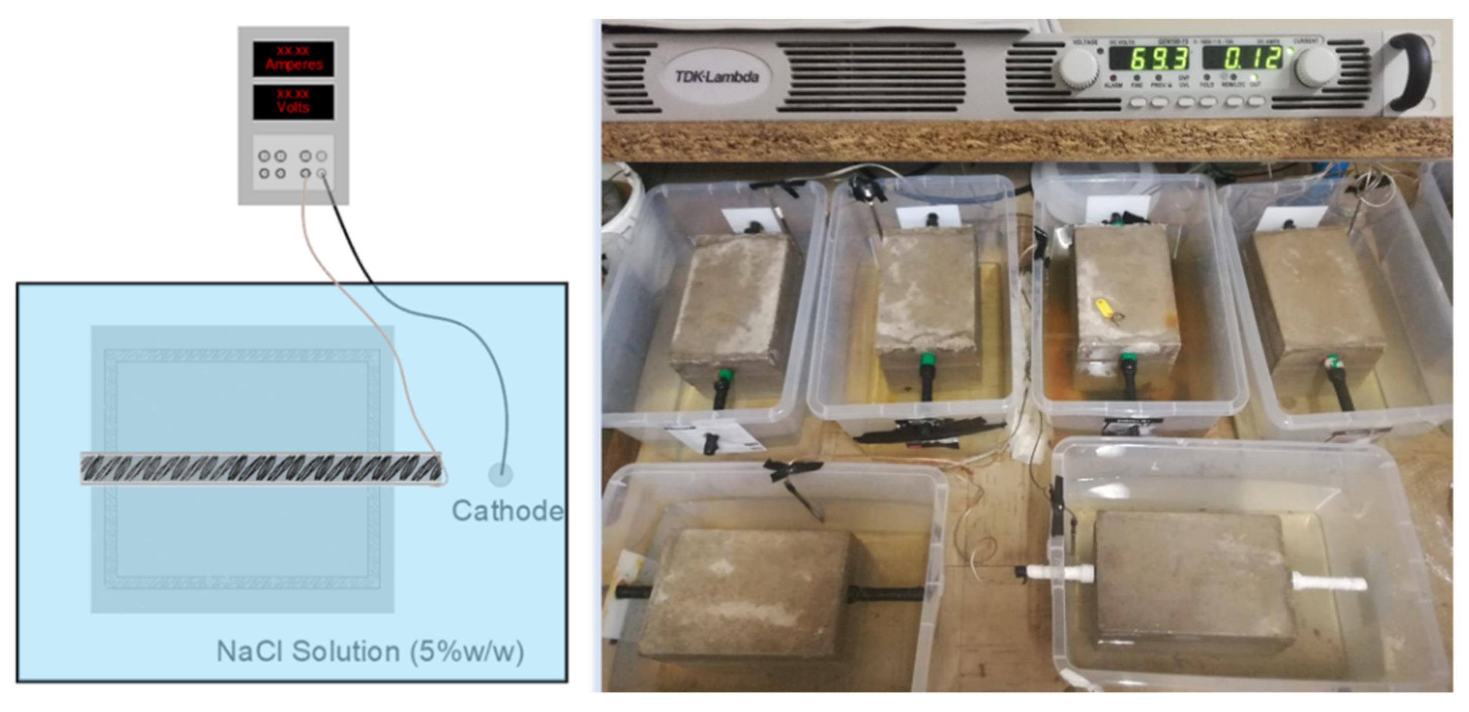
Upon the completion of the casting of the specimens (Figure 4), the accelerated corrosion process followed. All specimens were subjected to the impressed current density corrosion method, in which reinforcing rebars were immersed in a 5% sodium chloride solution by weight of water and connected to a power supply applying a direct electric current of 0.12 A (Figure 5). In order to reach different levels of corrosion damage on the main reinforcement, 1%, 2%, 3%, and 4% of mass loss, Faraday’s law was adopted to determine the necessary experimental accelerated corrosion times; hence, the specimens remained in the corrosion cells for different exposure times. It is customary in several experimental studies for the current to be imposed solely on the longitudinal and not in parallel on stirrups. For this purpose, stirrups of all specimens were covered with a special anti-corrosion coating (epoxy resin) in order to adequately maintain their corrosion resistance.
Figure 4.
RC specimen after concrete curing for 28 days.
Figure 5.
Schematic representation of accelerated corrosion technique (left); experiments of accelerated electro-corrosion in RC specimens (right).
After the completion of the accelerated corrosion tests, the main steel bars were carefully extracted for the RC specimens and cleaned with a bristle brush, followed by immersion in 3.5 g hexamethylene tetramine diluted in 500 mL hydrochloric acid according to the ASTM G1-90 standard [10] for removing corrosion oxides and debris. Afterwards, the corrosion damage of the steel bars was determined by gravimetric measurements in terms of mass loss according to the following equation:
where η is the percentage mass loss of the steel bar, Mref is the reference mass of the non-corroded bar, and Mcor is the final mass of the corroded bar after the corrosion tests.
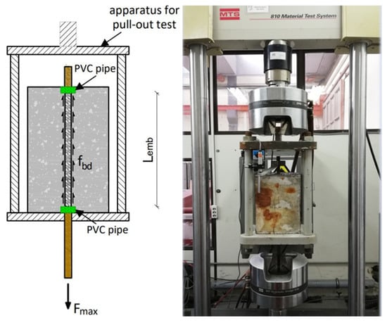
Pull out tests followed the corrosion process, based on the guidelines of ASTM C234-91a [11]. In the context of pull out tests, a special apparatus was designed to enable the applied force from the steel bar to be transferred directly to the concrete, preventing the development of bending moments (Figure 6). All tests were executed on a general-purpose servohydraulic machine MTS 250, where an external linear variable differential transformer (LVDT) was set to the free loaded end of the reinforcing bar to determine the relative slip between steel and concrete. All specimens were loaded under displacement control at a constant displacement rate of 0.2 mm/min and the bonding resistance was determined, as expressed in Equation (2):
where Fmax is the maximum pull out load, D stands for the nominal diameter of the main reinforcing bar, i.e., 16 mm, and Lemb stands for the embedded length, i.e., 250 mm.
Figure 6.
Schematic representation of pull out test set-up (left); pull out experiment of corroded RC specimen (right).
3. Results and Discussion
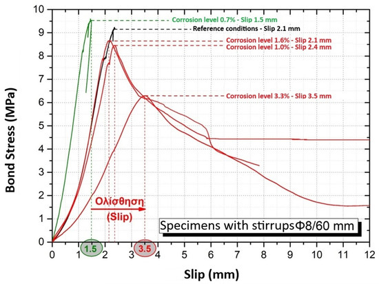
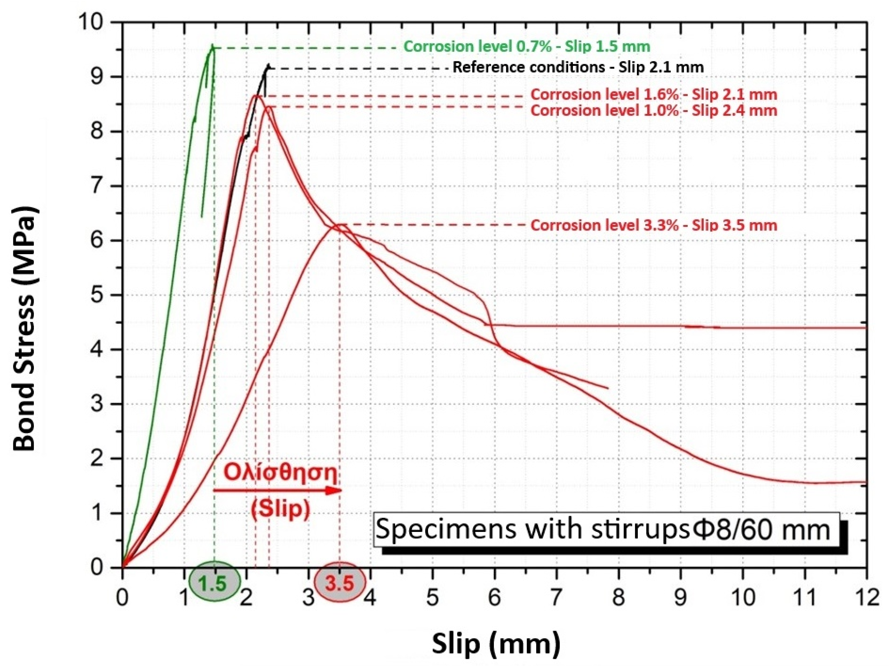
The curves of bond stress versus slip of the reinforcing bar, as extracted by the pull out tests on the RC specimens, are presented in Figure 7. The main results of the experiments are summarized in Table 1.
Figure 7.
Results of pull out tests. Curves of bond stress versus slip of steel reinforcing bar in non-corroded and corroded RC specimens.
Table 1.
Experimental results of corrosion tests and pull out tests.
It should be noted that for a very small corrosion level of up to 1%, an improvement of the bond behavior was observed, since a slight increase in the bond strength was recorded. This observation has already been depicted in similar experimental studies and is due to the oxides produced at this low initial corrosion stage, which increase the roughness and friction at the steel–concrete interface and is reflected in the increase in the bond strength. As expected, as the corrosion of the steel reinforcement increases, the bond strength is reduced and relative slip is increased. In particular, corrosion led to a significant drop of the bond strength from 9.2 MPa to 6.2 MPa (32.6% percentage reduction). Even at a low corrosion level, only a 3.3% mass loss of steel was recorded and at the same time the slippage of the corroded reinforcing bar at the maximum stress state was increased by about two times more than the corresponding bar in non-corroded conditions (3.5 mm from 1.5 mm) between the two materials.
At this point, it is particularly important to emphasize the influence of confinement (through stirrups) and corrosion on the failure mode of the specimens. In particular, as shown from the black and green curves in Figure 7, specimen 1 (without corrosion) and specimen 2 (corrosion level 0.7%) failed, not due to the pull out of the steel bar, but due to the failure of the steel bar under tension. This highlights the strong contribution of confinement with dense stirrups (Φ8/60 mm) to the anchorage of the bar. On the contrary, analyzing the curves of the remaining tested specimens, it emerges that corrosion has a primary and negative effect on the steel–concrete bond behavior, as it favors the increase in the slippage of the bar and its pull out from the concrete. The corroded RC specimens demonstrated a mixed split and pull out failure mode.
Extending the results of the pull out tests to the scale of RC columns with corroded steel reinforcements, the increase in slip of the steel bar in the anchorage zone will cause an increase in chord rotation and the total displacement of the top RC member. Taking into account Equation (1), the increase in slip of the reinforcing bar due to corrosion will result in a proportional increase in the chord rotation of the structural member, affecting its entire deformation. These results are particularly important when studying the structural capacity of existing RC structures, where design criteria are proposed in terms of the chord rotation of the structural members. The further increase in deformation due to steel corrosion should be taken into account so as not to lead to an overestimation of the available rotational capacity of the existing members and to reach reliable conclusions.
Our experimental results were obtained based on the fact that the examined bond length in our specimens was limited to 30 cm. At this point, it is worth noting that if the corroded length of a steel bar in a column extends to a multiple length (2 × 30 = 60 cm or 3 × 30 = 90 cm or 3 × 30 = 120 cm), then the resulting slip of the bar will be corresponding and will (with certainty) cause issues that further increase the horizontal displacement and the ultimate angle of rotation of the corroded RC member. Based on the abovementioned, the need to evaluate the extent of the corroded bar length could be emphasized and the evaluation (calibration) of the criterion of this almost-inevitable damage is put up for discussion, at least in the case of columns of existing (old) structures.
In contrast to the experimental findings, it is noteworthy that according to the Greek Code (KAN.EPE) of Structural Interventions for the assessment and strengthening of existing RC buildings, the magnitude of the chord rotation at yielding is assumed to remain constant regardless of the degree of corrosion of the reinforcement, as shown below. The reduction factor of yielding chord rotation due to steel corrosion rcor,y, which is the fraction of the chord rotation at yielding of a corroded element to the chord rotation at yielding in reference conditions (without corrosion), is proposed to be equal (Equation (3)). Based on the above, it seems that there is room for the further improvement of certain points of the existing regulations and. at the same time, more experimental projects should be carried out studying the influence of steel corrosion on the rotational capacity of RC members by conducting large-scale experiments, which will provide more reliable results.
4. Conclusions
From the study of the slippage of a steel reinforcing bar due to corrosion and its effect on the chord rotation and deformation of corroded RC members, the main conclusions are summarized below:
- The experimental results indicated an increase in slip of a steel reinforcement due to corrosion.
- In the case of corroded RC columns, the degraded local bond mechanism has a significant effect, not only in terms of the strength of the structural member, but also in its deformation capacity, since the increase in slip will further increase the actual chord rotation and the top’s displacement.
- The present study highlights the need to enhance existing technical regulations regarding the influence of steel corrosion on the structural behavior of corroded RC members and highlights the great importance of the contribution of the slippage of a steel reinforcing bar due to corrosion in the calculation of the limit chord rotation (column–beam), a term which is of major importance in the assessment of the structural integrity of old RC structures, as introduced as an adequacy requirement by both Eurocode 8-3 and the Greek Code of Structural Interventions (KAN.EPE).
Author Contributions
Investigation, C.A., M.B. and K.K.; writing—original draft preparation, C.A., M.B. and K.K.; writing—review and editing, C.A. and K.K.; supervision, C.A. All authors have read and agreed to the published version of the manuscript.
Funding
This research received no external funding.
Institutional Review Board Statement
Not applicable.
Informed Consent Statement
Not applicable.
Data Availability Statement
The data presented in this study are available upon request from the corresponding author.
Conflicts of Interest
The authors declare no conflicts of interest.
References
- Koulouris, K.; Apostolopoulos, C. Study of the Residual Bond Strength between Corroded Steel Bars and Concrete—A Comparison with the Recommendations of Fib Model Code 2010. Metals 2021, 11, 757. [Google Scholar] [CrossRef] [Scilit]
- Lin, H.; Zhao, Y.; Feng, P.; Ye, H.; Ozbolt, J.; Jiang, C.; Yang, J.-Q. State-of-the-art review on the bond properties of corroded reinforcing steel bar. Constr. Build. Mater. 2019, 213, 216–233. [Google Scholar] [CrossRef] [Scilit]
- Dai, K.; Daia, K.-Y.; Liua, C.; Lua, D.-G.; Yua, X.-H. Experimental investigation on seismic behavior of corroded RC columns under artificial climate environment and electrochemical chloride extraction: A comparative study. Constr. Build. Mater. 2020, 242, 118014. [Google Scholar] [CrossRef] [Scilit]
- Kioumarsi, M.; Benenato, A.; Ferracuti, B.; Imperatore, S. Residual Flexural Capacity of Corroded Prestressed Reinforced Concrete Beams. Metals 2021, 11, 442. [Google Scholar] [CrossRef] [Scilit]
- Vecchi, F.; Belletti, B. Capacity Assessment of Existing RC Columns. Buildings 2021, 11, 161. [Google Scholar] [CrossRef] [Scilit]
- Megalooikonomou, K.G.; Tastani, S.P.; Pantazopoulou, S.J. Effect of yield penetration on column plastic hinge length. Eng. Struct. 2018, 156, 161–174. [Google Scholar] [CrossRef] [Scilit]
- EN 1998-3:2005; Eurocode 8—Design of Structures for Earthquake Resistance—Part 3: Assessment and Retrofitting of Buildings. European Committee for Standardization (CEN): Brussels, Belgium, 2005.
- Tassios, T.P.; Kostikas, C.; Abakoumkin, V.; Vintzilaiou, E.; Vlachos, I.; Vougioukas, E.; Dritsos, S.; Theodorakis, S.; Kappos, A.; Plainis, P.; et al. Code of Structural Interventions (KAN.EΠE.), 3rd ed.; Earthquake Planning and Protection Organization: Athens, Greece, 2022. [Google Scholar]
- BS EN. 206-1; Concrete-Part 1: Specification, Performance, Production and Conformity. British Standards Institution: London, UK, 2000.
- ASTM G1-90; Standard Practice for Preparing, Cleaning, and Evaluating Corrosion Test Specimens. Annual Book of ASTM Standards, Vol. 3.02. ASTM: Philadelphia, PA, USA, 1993.
- ASTM C234-91a; Standard Test Method for Comparing Concretes on the Basis of the Bond Developed with Reinforcing Steel (Withdrawn 2000). ASTM International: West Conshohocken, PA, USA, 1991.

Disclaimer/Publisher’s Note: The statements, opinions and data contained in all publications are solely those of the individual author(s) and contributor(s) and not of MDPI and/or the editor(s). MDPI and/or the editor(s) disclaim responsibility for any injury to people or property resulting from any ideas, methods, instructions or products referred to in the content. |
© 2026 by the authors. Licensee MDPI, Basel, Switzerland. This article is an open access article distributed under the terms and conditions of the Creative Commons Attribution (CC BY) license.