


Abstract
It has been established that hydrogen diffusion can significantly influence the mechanical response of metallic materials under various loading conditions. This phenomenon is particularly evident in reducing the ability for macroscopic plastic deformation. The formation and collapse of bubbles inside a fluid, i.e., cavitation, near a solid surface, generates one of the most complex loading scenarios. The characteristics of localized, high-velocity, and cyclic loading inherent to this process may lead to material removal from the surface, a phenomenon known as cavitation erosion. The mechanical properties of the metal surface, affected by hydrogen, may alter the resistance against erosion wear under cyclic loading conditions during cavitation. In this research, 316L stainless steel samples were electrochemically charged in H2SO4 to assess the effect of diffused hydrogen on mechanical behavior, as determined by tensile and micro-indentation testing. The cavitation erosion experiments were conducted on hydrogen-charged and uncharged samples in an ultrasonic cavitation test rig. The findings showed that hydrogen diffusion resulted in a significant reduction of up to 80% in cavitation erosion damage after 5 h of testing compared to the uncharged sample. After seven days of storage, however, the cavitation erosion damage of the hydrogen-charged specimens returned to a level comparable to that of the uncharged specimens, indicating that the beneficial effect of hydrogen on cavitation erosion resistance is reversible. Following short-term cavitation exposure, notable plastic deformation was observed on the eroded surfaces of the uncharged specimens, particularly as raised grain boundaries and slip bands. In contrast, the surfaces of the hydrogen-charged specimens predominantly retained their integrity, suggesting an increased resistance to plastic deformation following hydrogen charging.
1. Introduction
The effects of diffusible hydrogen on the mechanical properties of metallic materials have been explained by several proposed mechanisms, including hydrogen-enhanced decohesion (HEDE), hydrogen-enhanced localized plasticity (HELP), and hydrogen-induced changes in stacking fault energy and vacancy formation [1,2,3,4]. Although hydrogen is generally associated with a loss of ductility in metallic materials, some studies have reported a positive effect on ductility. For example, hydrogen has been shown to increase the elongation of a Fe-30Mn-6Al alloy [3], an effect attributed to hydrogen-assisted deformation twinning, which enhances the work-hardening capacity. In addition, the work-hardening rate of hydrogen-charged samples from Fe–24Cr–19Ni alloy exceeds that of uncharged specimens at later stages of deformation (εt > 0.2), delaying plastic instability and improving uniform elongation [5].
In addition to its effects on ductility, hydrogen has also been reported to influence the strength of steels. While hydrogen-induced softening, characterized by a reduction in strength, has mainly been reported for non-austenitic steels [6,7,8,9], most studies on austenitic steels have reported hydrogen-induced strengthening [5,10,11,12,13,14,15,16,17,18,19,20]. Marchi et al. [12] have investigated the tensile properties of 316 alloys with different chemical compositions after gaseous hydrogen charging. Both the tensile flow stress and the strain-hardening rate of the tested materials increased due to hydrogen diffusion. In the work conducted by Ogawa et al. [14], gaseous hydrogen charging was applied to Fe-24Cr-19Ni austenitic stainless steel (310S), resulting in improvements in yield strength, ultimate tensile strength, and ductility. Remarkably, the introduction of hydrogen significantly increased the true fracture strength by more than 40% compared with the uncharged sample. The hydrogen-induced strengthening was also reported to increase the yield strength of Fe-15Cr-15Ni austenitic steel [11].
The enhancement in strength due to hydrogen incorporation is primarily attributed to solid-solution strengthening [5,20], governed by the dynamic interaction between diffusive hydrogen and moving dislocations. Two primary contributions to the flow stress have been identified: (i) hydrogen atoms acting as short-range, thermally activatable obstacles within the dislocation core, and (ii) resistance to dislocation motion arising from solute drag associated with a diffusible hydrogen atmosphere (i.e., a hydrogen Cottrell atmosphere) [19]. The latter originates from the limited ability of hydrogen atoms to overcome diffusion barriers and follow the dislocation core. The relative contribution of these mechanisms is strongly dependent on dislocation velocity, and thus on the applied strain rate. Specifically, the glide resistance associated with hydrogen atoms in the dislocation core increases with increasing dislocation velocity, whereas the solute-drag force initially increases and subsequently decreases. Consequently, maximum hydrogen-induced solid-solution strengthening is achieved when the combined contributions of these mechanisms are optimally balanced [18].
The strain rate also influences the susceptibility of materials to hydrogen embrittlement. Depover et al. [21] reported that hydrogen embrittlement of DP600 steel was significantly reduced as the tensile strain rate increased from 0.0167 to 1.67 s−1. Under dynamic loading conditions, at high strain rates of 450 and 900 s−1, the susceptibility to hydrogen embrittlement was further reduced. At low strain rates, the greater time available for hydrogen diffusion toward regions of high stress concentration, particularly ahead of crack tips, increases the likelihood of hydrogen-assisted failure [21].
The effect of hydrogen on the mechanical properties of 316L stainless steel has been broadly investigated [13,17,22,23,24,25,26,27]. Takakuwa et al. [17] studied 316L stainless steel using indentation testing following cathodic hydrogen charging in H2SO4. The yield stress increased from 304 MPa for the uncharged sample to 620 MPa after charging. After 384 h of storage, the yield stress returned to its original value, consistent with hydrogen desorption. Increases in surface hardness and fatigue resistance have been reported for both 304 and 316L stainless steels following gaseous hydrogen charging [13]. Near fatigue cracks, uncharged samples exhibited a greater number of slip bands compared to hydrogen-charged specimens. This behavior is attributed to hydrogen atoms trapped at dislocation cores, which increase the critical shear stress required for dislocation motion, producing a pinning effect. In contrast to the hardening effects, hydrogen-induced softening has also been observed in 316L stainless steel fabricated by laser powder bed fusion, which was primarily attributed to the elastic shielding effect of hydrogen, which weakens interactions (typically repulsive forces) between dislocations and between dislocations and other lattice defects [25].
Another factor that should be considered in assessing the effect of hydrogen on the mechanical properties of austenitic steels is its influence on stress-induced martensitic (SIM) transformation. Hydrogen has generally been reported to suppress SIM transformation in 316L stainless steel [23,28,29]. For example, hydrogen decreases the martensite fraction in 304 and 316L steels subjected to high-pressure torsion [28], which has been attributed to slip localization arising from hydrogen-enhanced slip planarity. Similarly, suppression of SIM during tensile deformation of 316L samples has been associated with a reduction in ductility [29].
The interaction between diffused hydrogen and tribological loading has been investigated, with reported effects on wear behavior varying depending on the material and testing conditions. Tribocorrosion studies of C45E steel (AISI 1045) following cathodic hydrogen charging demonstrated that hydrogen uptake promotes grain refinement in the subsurface region of the worn area [30]. This behavior was attributed to the inhibition of dislocation motion by hydrogen, which facilitates recrystallization and promotes the formation of nanocrystalline layers through severe plastic strain accumulation. Electrochemically hydrogenated AISI 316H exhibited a lower wear rate, higher hardness, and a slight increase in impact toughness compared with the uncharged condition [31]. In contrast, ball-on-disk wear tests conducted on X65, X70, and X80 pipeline steels showed an increase in wear rate following hydrogen charging, despite an accompanying increase in hardness [31]. Furthermore, impact-abrasive wear testing of bainitic steel revealed a deterioration in wear resistance in the presence of hydrogen, which was attributed to hydrogen-induced embrittlement [32]. The increased susceptibility to embrittlement resulted in greater microcrack formation both on the surface and in the near-surface region of the wear track [32].
Cavitation erosion is a form of surface mechanical damage that occurs due to the repeated collapse of gaseous bubbles on a solid surface within a fluid. Numerous studies have investigated the effect of surface treatments on mechanical damage under cavitation conditions [33,34,35,36]. It has been demonstrated that strain hardening in the near-surface region of 316L stainless steel results in the formation of a fine-grained crystalline layer with a depth of approximately 400 nm [33]. This refined surface layer enhances the resistance of the surface to cavitation-induced stresses generated by bubble collapse.
Our previous work [34] showed that the diffusion of oxygen into the surface of titanium can significantly increase surface hardness. Cavitation erosion tests revealed that the mass loss of the treated samples either increased or decreased relative to the untreated material, depending on the achieved surface hardness. Notably, a sample with a surface hardness of 800 HV exhibited a 90% improvement in erosion resistance compared to untreated titanium. Other diffusion-based hardening processes, including nitriding [35], carburizing [37], and boronising [38,39] have also been shown to enhance the cavitation erosion resistance of metallic materials.
Although extensive research has been conducted on the effect of hydrogen on the mechanical properties of bulk metallic materials, primarily through tensile, compression, and fatigue testing, its influence on cavitation erosion behavior remains largely unexplored. This gap is of particular interest because cavitation imposes a complex surface loading characterized by high strain rates and repeated transient impacts, which differ significantly from conventional mechanical testing conditions. Furthermore, in austenitic steels, hydrogen diffusion at room temperature is largely confined to the near-surface region. Therefore, investigating the cavitation erosion behavior of 316L stainless steel following cathodic hydrogen charging can provide valuable insights into the interaction between hydrogen-affected surface layers and cavitation-induced loading. Cavitation erosion experiments were conducted on both the as-received and solution-annealed 316L stainless steel to evaluate the effect of hydrogen charging in two distinct microstructural conditions.
2. Materials and Methods
2.1. Materials
316L stainless steel bars were used in both the as-received and solution-annealed conditions for the cavitation erosion tests. Specimens with dimensions of 22 × 22 × 7 mm3 were prepared using water-jet cutting. Some specimens were subsequently solution annealed at 1100 °C for 30 min, followed by water quenching. Before cavitation erosion testing, the samples were mounted and mechanically ground using silicon carbide papers with grit sizes of 220, 500, and 800, followed by polishing with a 6 µm abrasive suspension under a load of 20 N for 10 min in a half-automatic metallographic grinding machine. As the final preparation step, the specimen surfaces were manually polished using 4000-grit paper in a single direction to produce parallel scratch lines. This procedure was adopted to facilitate the identification of slip lines generated during cavitation erosion, as the orientation of the pre-existing scratches allows clearer differentiation from deformation-induced surface features after testing. The surface roughness of the prepared samples was measured to be Ra ≈ 0.02 µm.
Tensile tests were conducted on bulk 316L stainless steel specimens in the as-received condition using standard cylindrical specimens prepared in accordance with ASTM E8 [40]. The specimens had a gauge length of 50 mm and a gauge diameter of 8 mm. Before testing, the surface of the gauge section was polished using 1200-grit SiC paper, followed by polishing with 3 µm and 1 µm diamond suspensions to remove surface defects and ensure a uniform finish. In addition, a 20 µm thick metallic foil produced from the same material was used for tensile testing. The surface roughness of the foil was measured to be 0.1 µm. Rectangular tensile specimens with dimensions of 230 mm in length and 12.5 mm in width were cut from the foil sheets using a precision cutter according to ASTM E345 [41]. For optical microstructural analysis, the specimens were electrochemically etched in 10% oxalic acid at 12 V for 40 s [42].
2.2. Hydrogen Charging
Cathodic hydrogen charging was performed in an aqueous electrolyte containing 0.05 M H2SO4 with 0.4 wt.% NH4SCN under a constant current density of 10 mA/cm2 for 24 h. To maintain the same current density across all specimens, the exposed surface areas of the cavitation-erosion and tensile samples were first measured, and the required charging current was then calculated for each sample. For the hydrogen charging setup, an electrical wire was welded to each specimen to ensure stable electrical contact. During charging, the steel specimens served as the cathode, while a platinum-coated titanium mesh served as the anode. To evaluate the effect of hydrogen effusion on the cavitation erosion behavior, a subset of the hydrogen-charged specimens was stored at room temperature for 7 days before cavitation erosion testing.
2.3. Cavitation Erosion
Cavitation erosion tests were performed in distilled water using an ultrasonic cavitation rig according to ASTM G32 standard [43]. Replaceable stainless steel tips with a diameter of 16 mm were mounted at the end of the sonotrode. The sonotrode-tip assembly oscillated at a frequency of 20 kHz with a peak-to-peak amplitude of 40 µm, generating cavitation bubbles in the surrounding liquid. The samples were positioned beneath the vibrating tip, maintaining two parallel surfaces separated by a distance of 0.5 mm between the specimen surface and the tip. During prolonged testing, the surface of the tips gradually became roughened due to cavitation damage. Therefore, the tips were replaced after every 10 h of cavitation erosion testing to ensure consistent testing conditions. The experiments were conducted in a double-walled container connected to a chiller to maintain the cavitation medium at a constant temperature of 25 ± 3 °C. Before testing, the specimens were cleaned in an ultrasonic bath containing ethanol for 3 min, then air-dried. The samples were subsequently placed in a vacuum chamber for 2 min to ensure complete removal of any residual liquid from the surface. The initial mass of each sample was then measured using an analytical balance with an accuracy of 0.1 mg. At predetermined intervals during the cavitation erosion test, the specimens were removed from the holder, cleaned using the same procedure described above, and weighed again to determine the mass loss. Three samples were tested for each condition, and the average cumulative mass loss is presented. A scanning electron microscope (SEM; Leo 1530 Gemini, Zeiss GmbH, Jena, Germany) was used to investigate the eroded surfaces and subsurfaces. Electron backscatter diffraction (EBSD; Digiview IV CCD camera with OIM 7.3.1 data collection and analysis software, EDAX Inc., Pleasanton, CA, USA) was also performed on cross-sections of the eroded samples.
2.4. Mechanical Testing
Tensile tests were performed on both cylindrical specimens and foil specimens using a universal tensile testing machine (Quasar 100, Galdabini, Cardano al Campo, Italy). The specimens were loaded at a constant strain rate of 2 × 10⁻⁴ s−1 until fracture. The experiments lasted approximately 25 min for the cylindrical specimens and 3 min for the foil specimens. For the cylindrical specimens, an extensometer was used to precisely measure the elongation during testing. For the foil specimens, 320-grit silicon carbide paper was placed between the 50 mm ends of the specimens and the wedge grips of the tensile testing machine to prevent tearing and slippage during testing. This procedure was implemented in accordance with the recommendations of ASTM E345 [41] for tensile testing of thin metallic foils. All tensile tests were repeated at least three times, and the average mechanical properties were determined from the resulting stress–strain curves.
Microhardness tests were performed on the surfaces of both charged and uncharged samples. A low normal load of 25 g applied for 10 s was used to minimize the indentation depth and to approximate the hardness of the near-surface material. Hardness measurements were also conducted after varying periods of storage at room temperature to assess the effect of hydrogen effusion on surface hardness. For each sample, at least five indentations were made, and the reported hardness values represent the average of these measurements.
2.5. Secondary Ion Mass Spectrometry (SIMS)
SIMS measurements were performed on samples (10 × 10 × 7 mm3) before and after hydrogen charging in the solution-annealed condition. The specimens were introduced into the vacuum chamber of a time-of-flight secondary ion mass spectrometer (TOF-SIMS5-100, IONTOF GmbH, Münster, Germany). Interlaced sputtering was carried out using O2+ primary ions over an area of 400 × 400 µm2 at an acceleration voltage of 2 kV. Mass spectrometry analysis was performed using Bi+ primary ions within a raster square of 100 × 100 µm2 at 30 kV, operated in positive polarity. The secondary ions H+ and Fe+ were selected for analysis. The total sputtering time and the total analysed depth were used to determine the mean sputtering rate (µm·s−1). This calibration allowed conversion of the analysis time into the corresponding depth.
3. Results
3.1. Microstructural Characterization
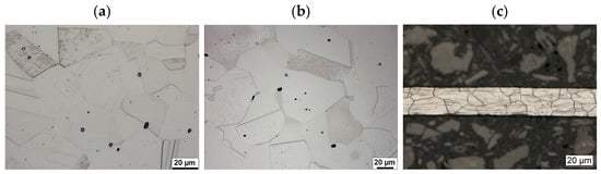
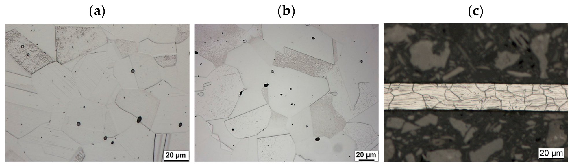
Figure 1 presents optical micrographs of the bulk and foil materials. In addition to grain and twin boundaries, slip bands are visible in the as-received samples, particularly in the foil specimen (Figure 1c). These features are attributed to prior plastic deformation during the manufacturing process. Comparison of Figure 1a,b shows that the grain size after solution annealing does not differ significantly from that of the as-received material. Further details of the microstructures of the as-received and solution-annealed samples are provided in our previous study [42].
Figure 1.
Microstructures of the different specimens: (a) bulk as-received 316L, (b) bulk solution-annealed 316L, and (c) 316L foil.
3.2. Cavitation Erosion Behavior
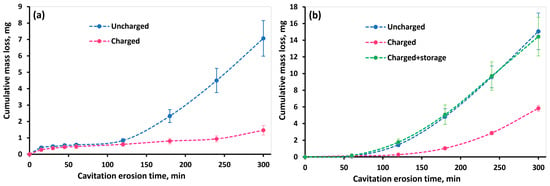
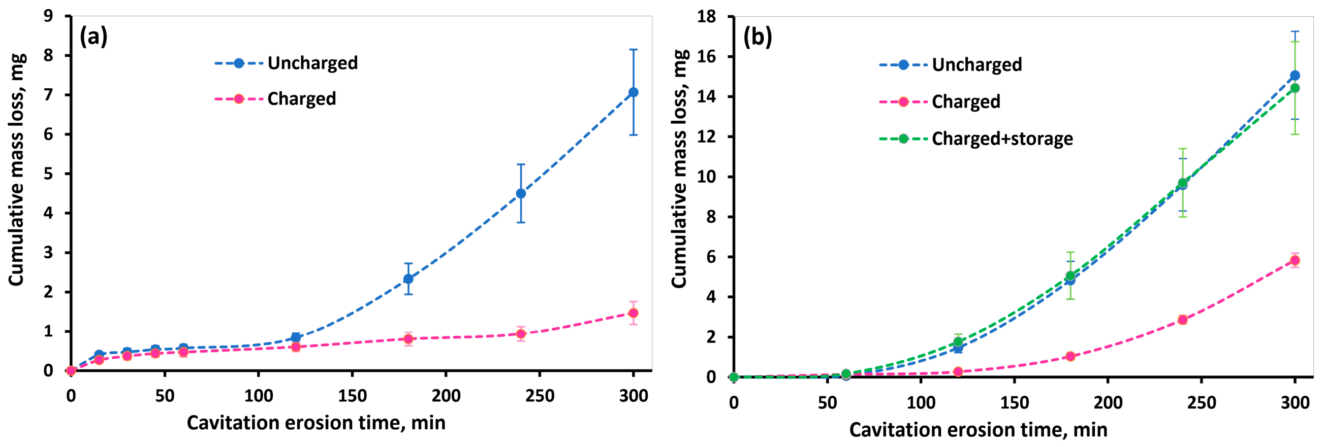
Figure 2 shows the cumulative mass loss of the as-received and solution-annealed 316L stainless steel specimens in both the hydrogen-charged and uncharged conditions. For the solution-annealed specimens, the cumulative mass loss of the hydrogen-charged samples tested after 7 days of storage is also presented in Figure 2b. Comparison of the cumulative mass loss of the as-received and solution-annealed specimens reveals that the as-received material exhibited lower mass loss under both charged and uncharged conditions. Similar behavior has been reported previously for the same material and was attributed to the mild prior strain hardening present in the as-received condition [42]. The strain-hardened microstructure enhances the surface resistance to plastic deformation under the repetitive impact stresses generated by cavitation bubble collapse, thereby improving cavitation erosion resistance.
Figure 2.
Cumulative mass loss of hydrogen-charged and uncharged 316L stainless steel samples as a function of cavitation erosion time under (a) as-received and (b) solution-annealed conditions. The results for the solution-annealed pre-charged specimens tested after 7 days of storage are also included in (b).
For both the as-received and solution-annealed specimens, a significantly lower cumulative mass loss was observed after 5 h of cavitation erosion for the charged samples compared with the uncharged samples, indicating a beneficial effect of hydrogen diffusion on cavitation erosion resistance. The reduction in cumulative mass loss reached up to 80% for the as-received specimens and 60% for the solution-annealed specimens.
After 7 days of storage at room temperature, the solution-annealed charged specimens exhibited a cumulative mass loss comparable to that of the uncharged specimens, as shown in Figure 2b. This result indicates that the effect of hydrogen on cavitation erosion resistance is reversible and diminishes as diffusible hydrogen effuses from the material. Furthermore, this observation confirms that the changes in cavitation erosion behavior after hydrogen charging are primarily associated with the presence of diffused hydrogen rather than with any possible irreversible chemical reactions or corrosion products formed on the surface during the charging process.
Figure 2a shows that, during the first 2 h of cavitation erosion, the cumulative mass loss of both the charged and uncharged as-received specimens remained negligible, indicating that they were predominantly within the incubation stage. With continued cavitation exposure, the cumulative mass loss of the uncharged specimen increased markedly. In contrast, the charged specimen maintained a very low mass loss even after 5 h of cavitation erosion. This indicates that a clear transition between the deformation-dominated incubation period and the following pronounced increase in erosion rate caused by the onset of larger pieces of material breaking off from the surface is significantly delayed by prior hydrogen charging.
A similar trend was observed for the solution-annealed specimens, as shown in Figure 2b. Although the uncharged specimen exhibited a cumulative mass loss of approximately 1.7 mg after 2 h of cavitation erosion, the mass loss remained considerably lower (≈0.3 mg) for the charged sample at this test duration. These results indicate that hydrogen charging also prolonged the incubation period of the solution-annealed material, although the improvement during the following test duration was less pronounced than that observed for the as-received condition.
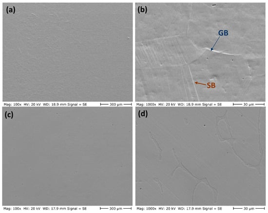
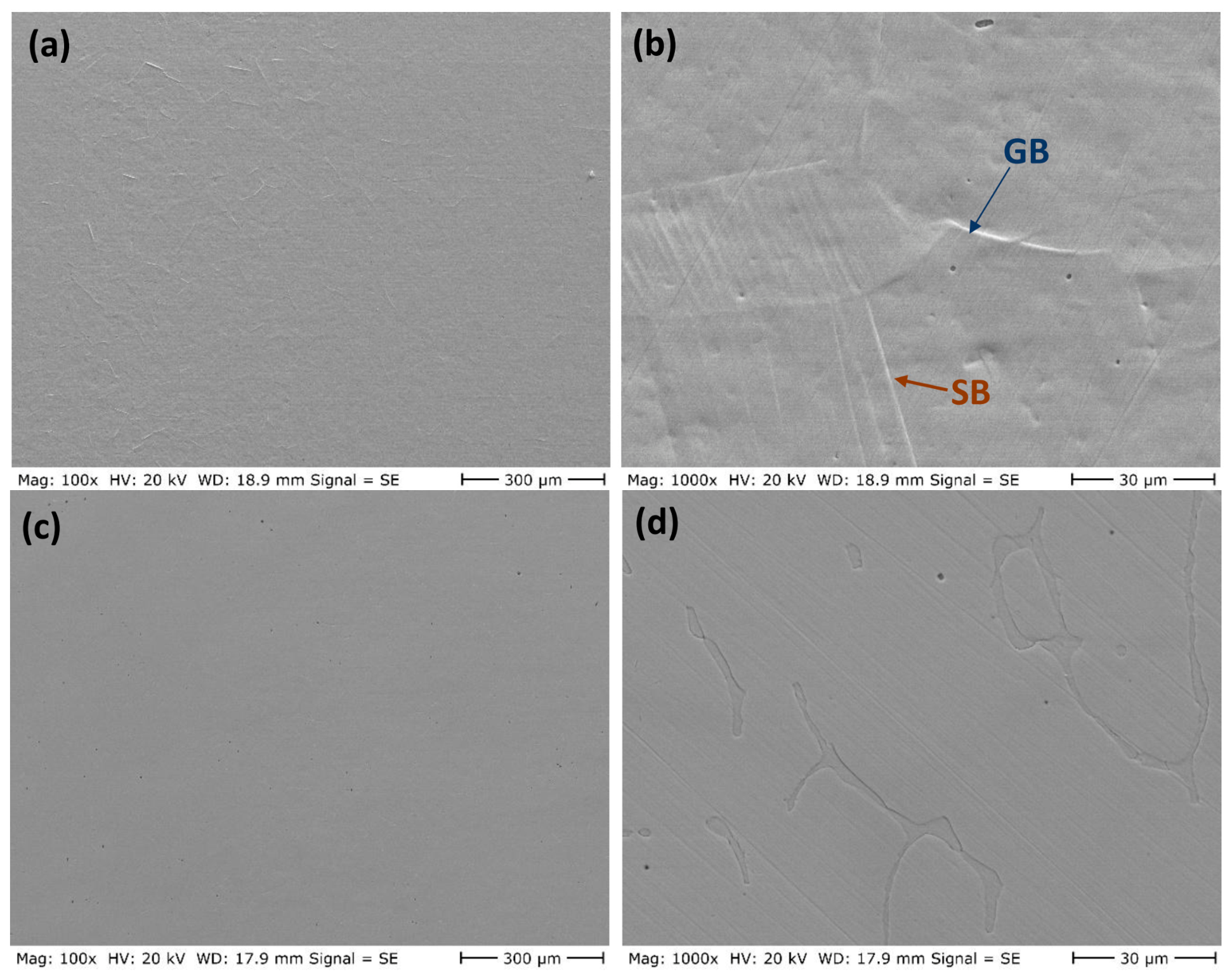
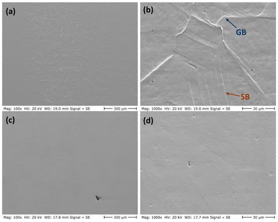
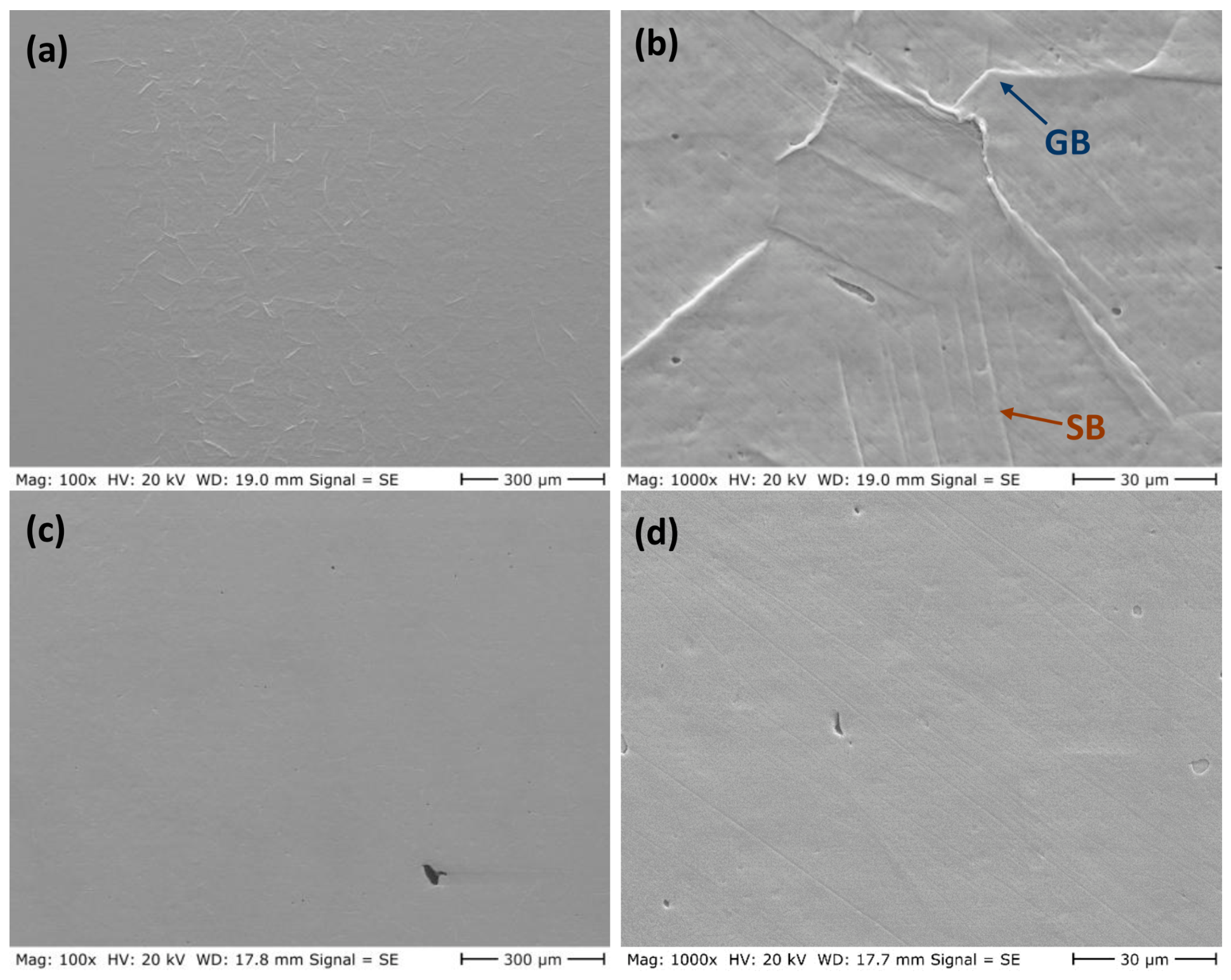
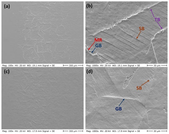
The evolution of the eroded surfaces of the charged and uncharged as-received samples at different cavitation erosion times is presented in Figure 3, Figure 4, Figure 5, Figure 6 and Figure 7. After 15 min of cavitation erosion (Figure 3a,b), the uncharged sample exhibited minor plastic deformation characterized by slip bands and the emergence of grain boundaries. As the erosion time increased to 30 min (Figure 4a,b), the extent of plastic deformation increased noticeably, although no clear evidence of material removal was observed at this stage. In contrast, the charged samples showed almost no visible plastic deformation after 15 and 30 min of cavitation erosion (Figure 3 and Figure 4), suggesting that hydrogen charging suppressed the surface plastic deformation induced by cavitation impacts.
Figure 3.
Eroded surfaces of the as-received material after 15 min of cavitation erosion: (a,b) uncharged sample and (c,d) charged sample. GB: deformed grain boundary; SB: slip band.
Figure 4.
Eroded surfaces of the as-received material after 30 min of cavitation erosion: (a,b) uncharged sample and (c,d) charged sample. GB: deformed grain boundary; SB: slip band.
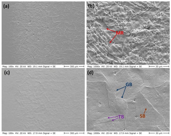
Figure 5.
Eroded surfaces of the as-received material after 60 min of cavitation erosion: (a,b) uncharged sample and (c,d) charged sample. GB: deformed grain boundary; TB: deformed twinning boundary; SB: slip band; MR: material removal due to cavitation erosion.
Figure 6.
Eroded surfaces of the as-received material after 2 h of cavitation erosion: (a,b) uncharged sample and (c,d) charged sample. GB: deformed grain boundary; TB: deformed twinning boundary; SB: slip band; MR: material removal due to cavitation erosion.
Figure 7.
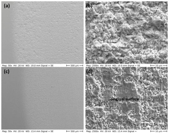
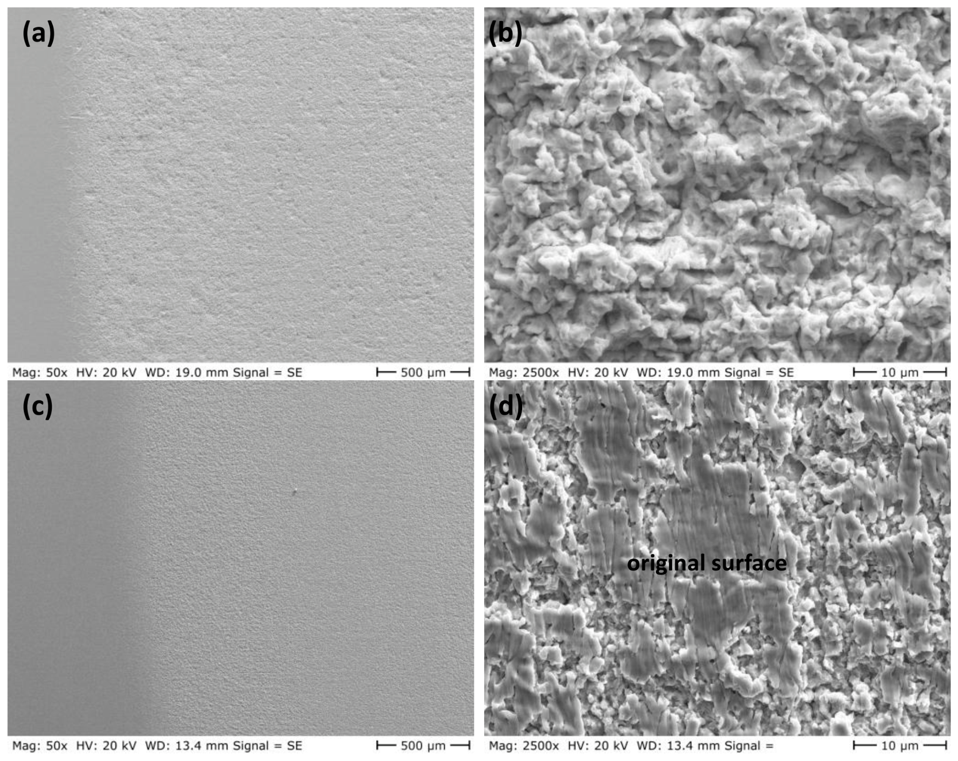
Eroded surfaces of the as-received material after 5 h of cavitation erosion: (a,b) uncharged sample and (c,d) charged sample.
After 1 h of cavitation erosion (Figure 5), the uncharged sample exhibited pronounced plastic deformation together with localized material removal. For the charged sample, although limited plastic deformation led to the emergence of grain boundaries in some regions, the overall degree of plastic deformation remained significantly lower than that observed in the uncharged sample. After 2 h of cavitation erosion, the area affected by material removal expanded over most of the cavitation erosion zone in the charged sample in Figure 6, although the original surface morphology was largely preserved. In contrast, the uncharged sample exhibited extensive plastic deformation characterized by widespread slip bands and clearly revealed grain boundaries, while material removal was still limited. Both charged and uncharged samples remained in the incubation phase during the early stages of cavitation erosion, with the uncharged sample approaching the end of this phase. The subsequent increase in mass loss of the uncharged sample after 2 h, as illustrated in Figure 2a, supports this observation.
After 5 h of cavitation erosion, Figure 7 reveals extensive plastic deformation on the eroded surface of the uncharged sample, which is characteristic of ductile austenitic steels [44,45]. Owing to the removal of the originally polished surface and the resulting surface roughening, microstructural features such as grain boundaries, deformation twins, and slip bands are no longer clearly observable. In contrast, although localized material removal occurs in certain regions of the hydrogen-charged sample, portions of the original surface remain intact (Figure 7d). This suggests that the hydrogen-charged material exhibits a degree of resistance to cavitation-induced stresses even after 5 h of exposure. The limited material removal is consistent with the relatively low cumulative weight loss measured for this sample, which remains below 2 mg in Figure 2a.
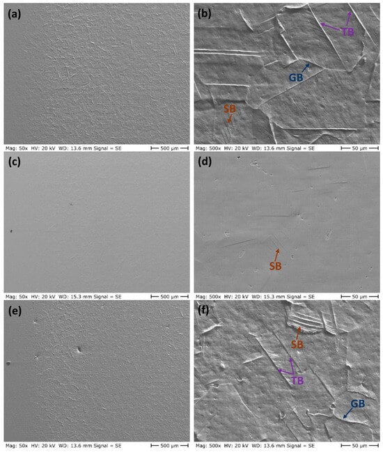
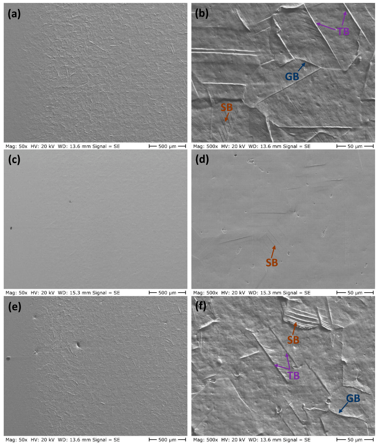
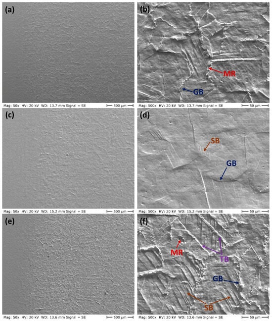
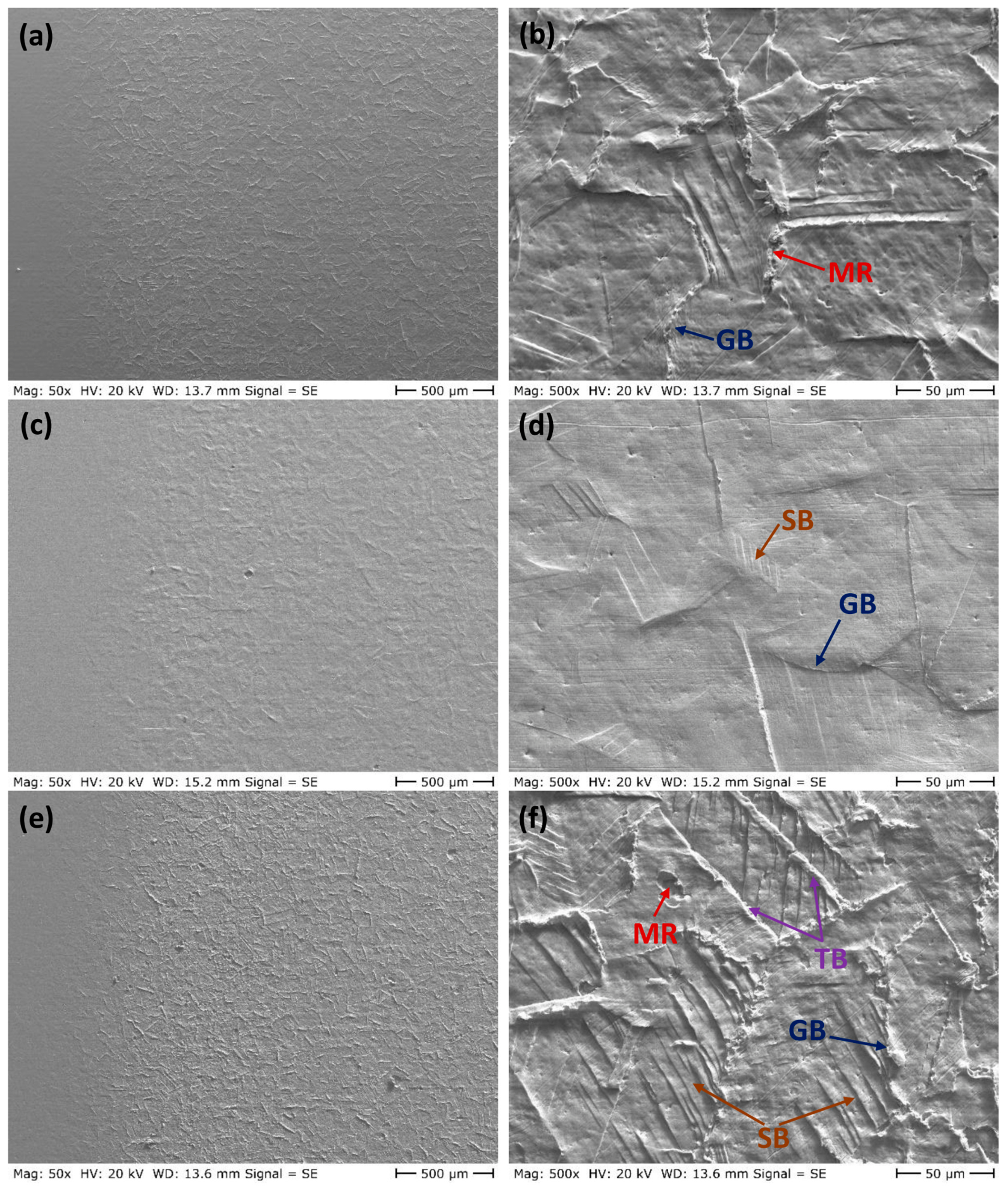
Typical SEM micrographs of the eroded surfaces of the solution-annealed specimens after 30 and 60 min of cavitation erosion are presented in Figure 8 and Figure 9, respectively. Comparison of the uncharged and hydrogen-charged specimens reveals a trend similar to that observed for the as-received condition, with the charged specimens exhibiting substantially less plastic deformation and surface damage than the uncharged specimens. This observation is also consistent with the improved cavitation erosion resistance of the charged material in Figure 2b.
Figure 8.
Eroded surfaces of the solution-annealed samples after 30 min of cavitation erosion: (a,b) uncharged specimen, (c,d) charged specimen, and (e,f) charged specimen after 7 days of storage. GB: deformed grain boundary; TB: deformed twinning boundary; SB: slip band.
Figure 9.
Eroded surfaces of the solution-annealed samples after 60 min of cavitation erosion: (a,b) uncharged specimen, (c,d) charged specimen, and (e,f) charged specimen after 7 days of storage. GB: deformed grain boundary; TB: deformed twinning boundary; SB: slip band; MR: material removal due to cavitation erosion.
A notable feature of the SEM images in Figure 8 and Figure 9 is the surface morphology of the charged specimens after 7 days of storage. These specimens exhibited surface damage and plastic deformation comparable to those of the uncharged specimens and markedly more severe than those of the freshly charged specimens. This observation is in good agreement with the cavitation erosion results shown in Figure 2b, where the cumulative mass loss of the charged specimens after 7 days of storage closely matches that of the uncharged specimens.
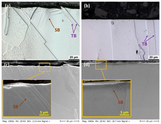
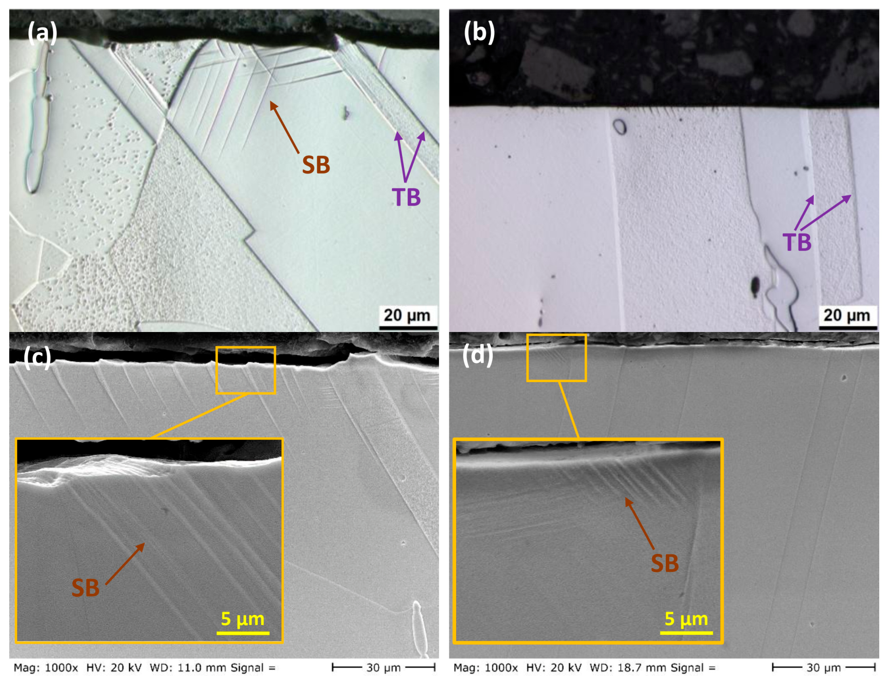
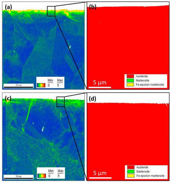
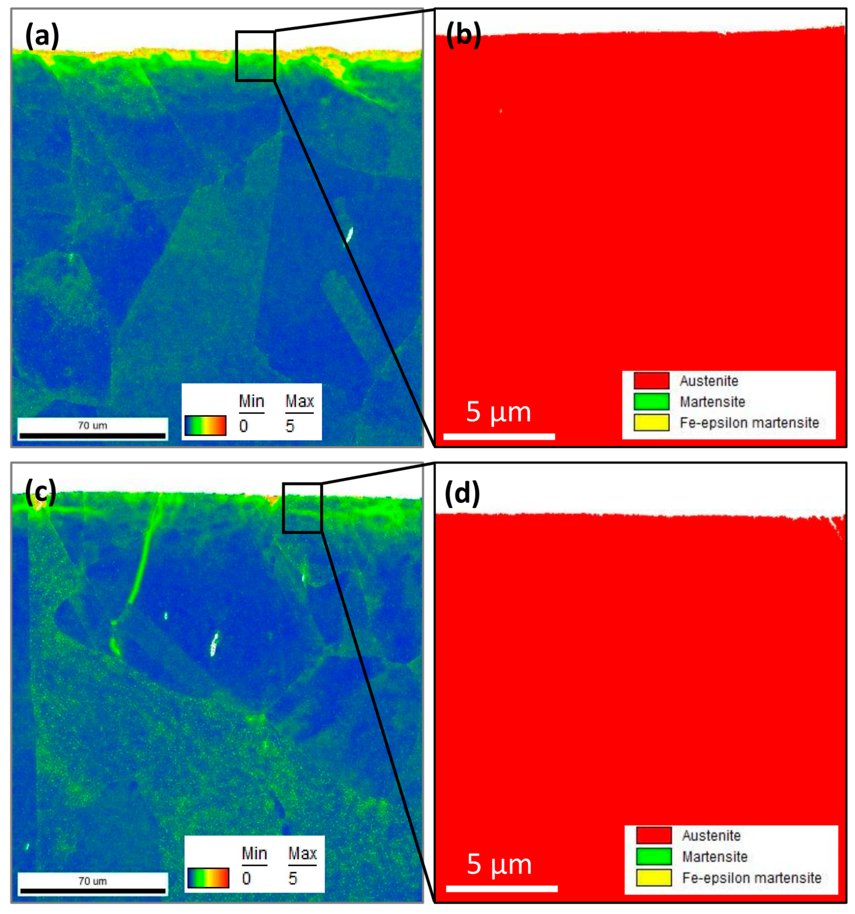
To further investigate the effect of diffused hydrogen on the suppression of plastic deformation, cross-sectional views of the solution-annealed samples after 1 h of cavitation erosion are shown in Figure 10. The figures show the emergence of slip lines beneath the eroded surface of the uncharged sample, extending to a depth of approximately 30 µm. In contrast, for the charged sample, only localized slip lines with a depth of about 5 µm were observed. These observations confirm the effect of hydrogen in suppressing plastic deformation under cavitation loading conditions. EBSD measurements of the cross-sections of these samples are shown in Figure 11. The kernel average misorientation (KAM) maps in Figure 11a,c reveal cavitation-induced localized strain in the near-surface region of both samples, with more pronounced strain observed in the uncharged sample. No evidence of stress-induced martensitic (SIM) transformation was detected in the near-surface regions (Figure 11b,d) in either the hydrogen-charged or uncharged condition.
Figure 10.
Cross-sectional views of the solution-annealed 316L stainless steel specimens after 1 h of cavitation erosion: (a,c) uncharged samples and (b,d) charged samples. The insets in (c,d) show higher-magnification views. TB: twinning boundary; SB: slip band.
Figure 11.
EBSD maps obtained from cross-sections of (a,b) uncharged and (c,d) hydrogen-charged samples after 1 h of cavitation erosion.
3.3. Mechanical Properties
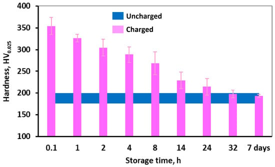
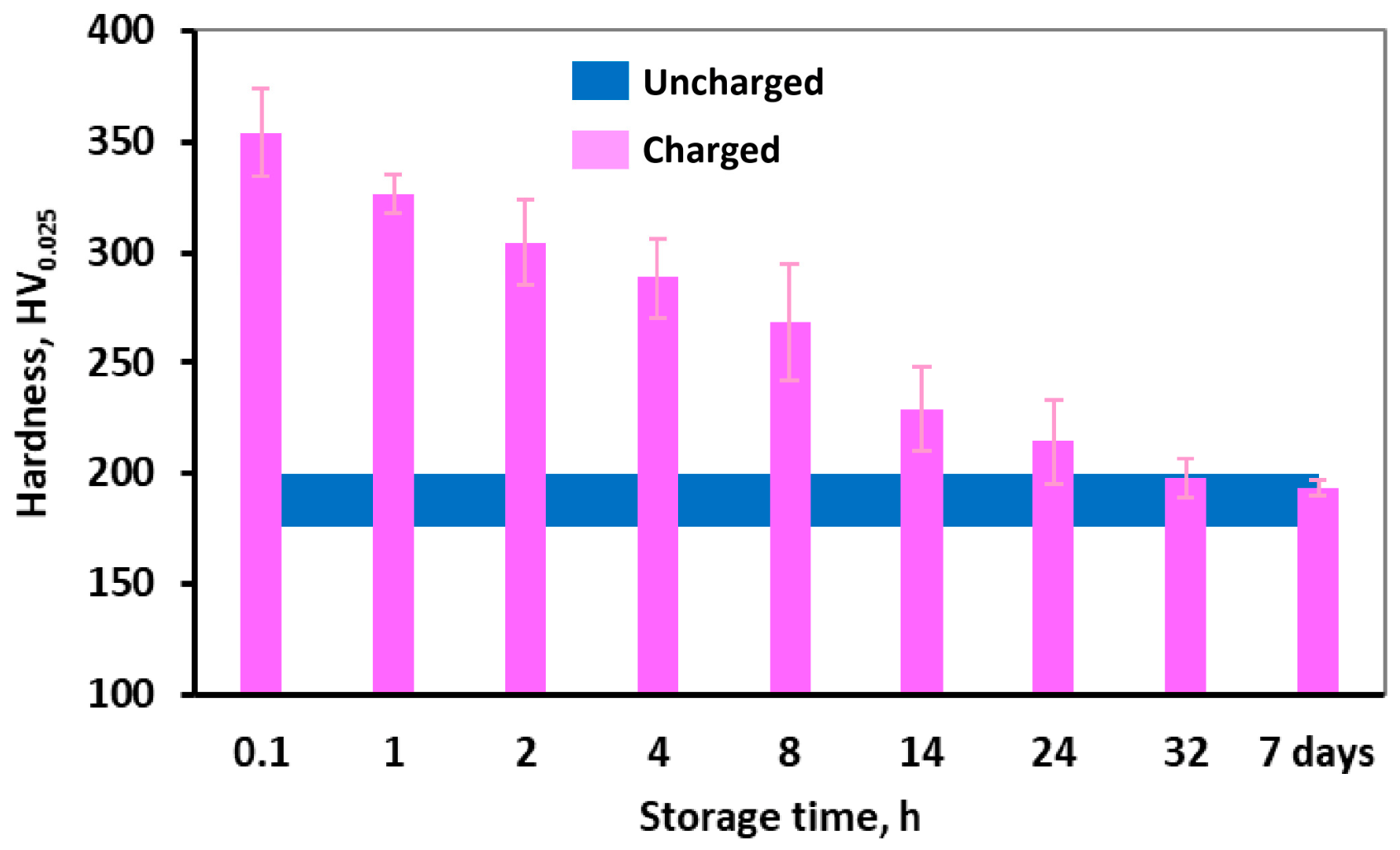
The surface hardness of the solution-annealed 316L stainless steel samples before and after hydrogen charging is shown in Figure 12. The uncharged sample exhibited a hardness of approximately 190 HV, which increased to 350 HV after hydrogen charging, corresponding to an increase of over 80% due to hydrogen diffusion. Figure 12 also demonstrates that, upon storage at room temperature, the hardness gradually decreases, returning to its original value before charging after 32 h of storage and remains nearly constant after 7 days of storage. This indicates that the hydrogen diffused into the surface layers is largely effused at room temperature, diminishing its effect on the surface hardness.
Figure 12.
Surface hardness of the solution-annealed 316L stainless steel specimens after hydrogen charging and subsequent storage at room temperature for different durations.
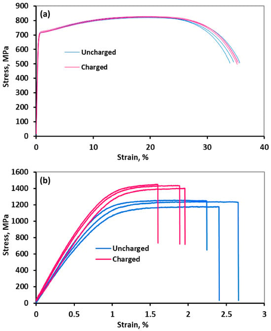
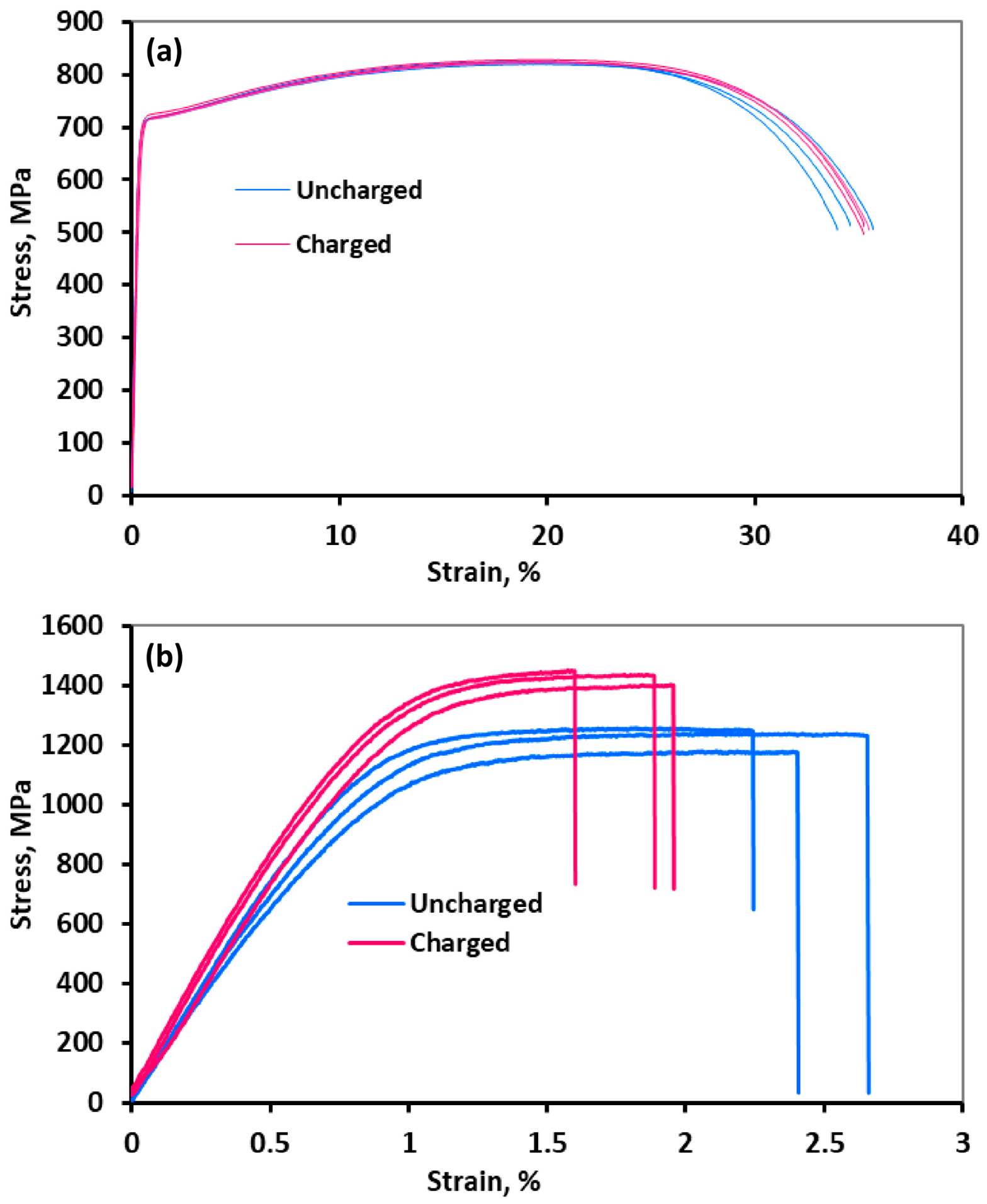
Engineering stress–strain curves for charged and uncharged samples, obtained from both cylindrical and foil specimens, are shown in Figure 13. The corresponding ultimate tensile strength (UTS) and fracture strains are summarized in Table 1. The curves for the cylindrical samples indicate minimal differences between charged and uncharged states, suggesting that room-temperature hydrogen charging does not significantly affect the strength or ductility of bulk specimens. In contrast, the foil samples exhibit a different behavior. As shown in Figure 13b and Table 1, hydrogen charging resulted in an approximately 15% increase in strength accompanied by a 20% reduction in ductility. This contrasting behavior between bulk and foil samples is likely due to the limited penetration depth of hydrogen, as discussed later.
Figure 13.
Engineering stress–strain curves for the charged and uncharged samples, obtained from bulk cylindrical samples (a) and thin foil samples (b).
Table 1.
Mechanical properties of the samples derived from the stress–strain curves shown in Figure 13.
3.4. Hydrogen Diffusion
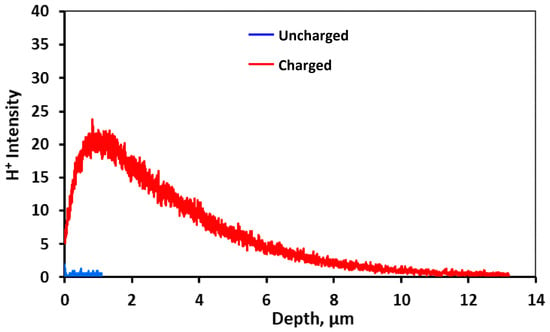
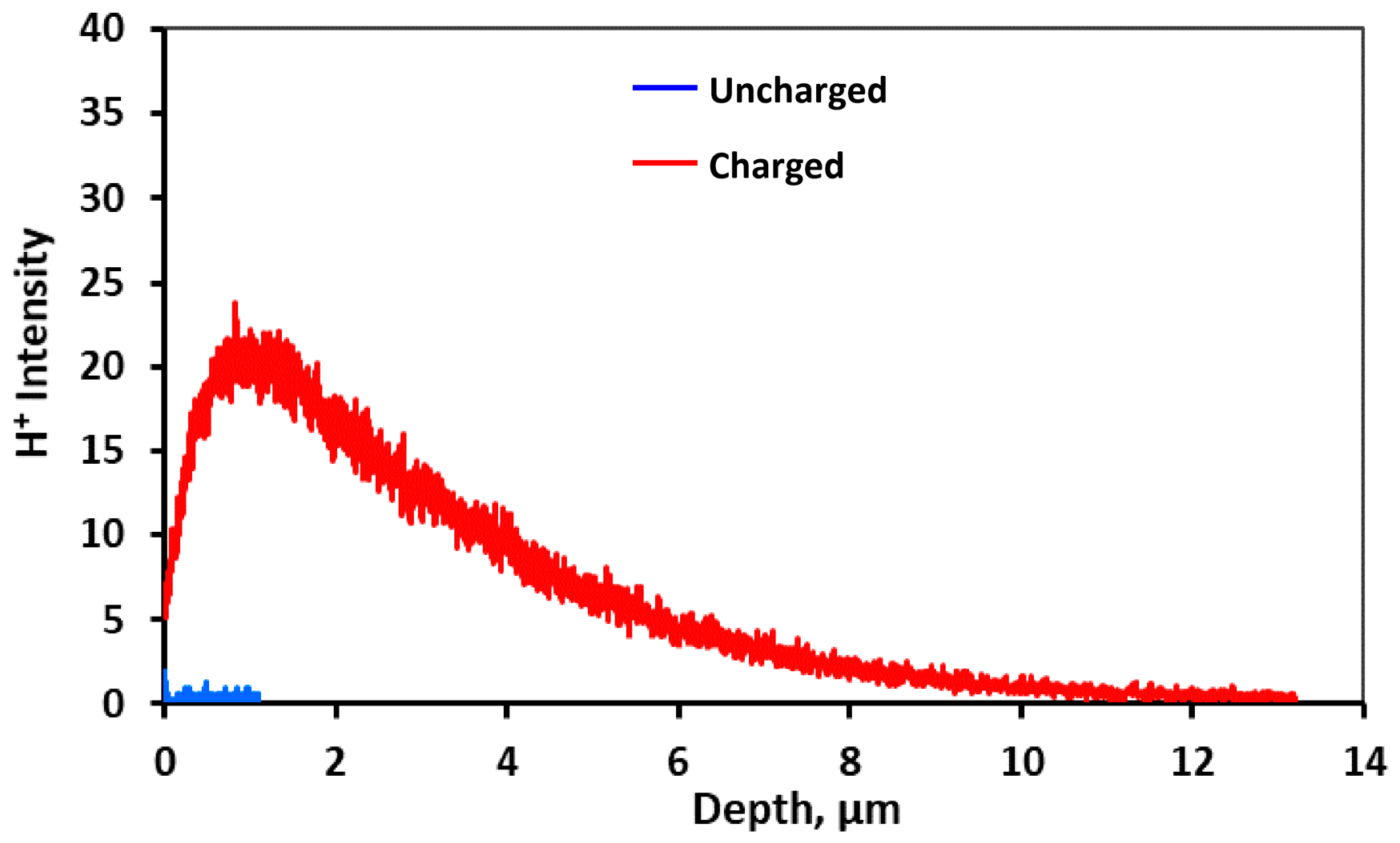
Figure 14 presents the hydrogen profile of a solution-annealed charged sample from the surface to a depth obtained through SIMS measurements. As a reference, the measurement was also performed on the surface of an uncharged sample, and the results are included in Figure 14. For the uncharged sample, measurements were limited to a depth of 1 µm, as no significant variation in hydrogen content was observed, and the hydrogen intensity remained close to zero. For the charged sample, an increase in hydrogen intensity was observed from the surface to a depth of 1 µm, followed by a gradual decrease at greater depths, indicating a lower hydrogen concentration in the immediate surface layer compared to the depth of 1 µm. The sample was stored in liquid nitrogen after charging to minimize hydrogen effusion; however, approximately 45 min elapsed between removal of the sample from the liquid nitrogen to the start of SIMS measurements, including the time required for vacuum preparation and gun warming. Hydrogen desorption during this period may explain the reduced hydrogen content in the near-surface layers. The decreasing trend in hydrogen intensity from 1 µm to greater depths indicates that hydrogen primarily accumulates near the surface, with the SIMS profile showing a hydrogen-affected region extending to approximately 12 µm in this sample. This depth should be regarded as an approximate value indicated by the SIMS profile rather than an exact quantitative hydrogen diffusion depth. A surface hydrogen concentration of 600 ppm was reported for 316L after cathodic charging at 30 mA/cm2 for 25 h [27]. The depth of hydrogen diffusion in the 316L sample after cathodic charging was reported to be limited to 10 µm because of the low value of the hydrogen diffusion coefficient in austenitic stainless steels at room temperature [46]. In tensile tests on pre-charged 304 stainless steel samples, brittle behavior at the fracture surface was reported to extend to roughly 70 µm below the sample outer surface when hydrogen was introduced via electrochemical charging [47]. Regardless of the fracture surface location, specimens pre-charged with gaseous hydrogen consistently exhibited brittle fractures. These observations confirmed the limited diffusion depth of hydrogen during electrochemical charging at room temperature for austenitic stainless steels [47].
Figure 14.
Hydrogen intensity profile for charged and uncharged samples. Measurements for the uncharged sample were limited to a depth of 1 µm, as no variation in hydrogen content was observed below the surface.
4. Discussion
4.1. Effect of Hydrogen Charging on Mechanical Properties
It is well established that hydrogen introduced via cathodic charging diffuses only to a limited depth in austenitic steels. The results shown in Figure 14 confirm a hydrogen-affected near-surface region extending to approximately 12 µm after 24 h of cathodic charging at an applied current density of 10 mA/cm2 in an H2SO4 solution. Consequently, conventional mechanical testing of bulk specimens (Figure 13a) is unlikely to reveal a significant influence of hydrogen on the overall mechanical response, as the affected region is confined to a shallow surface layer. To capture such localized effects, near-surface-sensitive techniques are required. In this context, low-load indentation testing and tensile testing of thin specimens with thicknesses comparable to the hydrogen diffusion depth provide a more reliable assessment of hydrogen-induced changes.
In the present study, the maximum indentation depth under an applied load of 25 g was measured by confocal microscopy to be less than 2 µm. This depth is significantly smaller than the hydrogen diffusion depth, indicating that the indentation response is predominantly governed by the hydrogen-enriched near-surface region. Therefore, the hardness values presented in Figure 12 are representative of the hydrogen-enriched surface layer. Moreover, the observed decrease in hardness with time eliminates the possibility that the initially elevated hardness is associated with the formation of corrosion products during cathodic charging. In contrast, for bulk tensile specimens with a diameter of 8 mm, the fraction of the material affected by hydrogen is negligible. Assuming a hydrogen-affected surface layer approximately 12 µm thick, the affected cross-sectional area is only about 0.30 mm2, corresponding to approximately 0.6% of the total cross-sectional area (50.3 mm2). It is therefore not unexpected that the results presented in Figure 13a and Table 1 show no measurable effect of hydrogen on the mechanical properties of these samples.
However, in the case of foil specimens, where the thickness is comparable to the hydrogen diffusion depth, the influence of hydrogen becomes pronounced. As shown in Figure 13b and Table 1, hydrogen charging leads to an increase in both yield strength and ultimate tensile strength, accompanied by a reduction in ductility. Similar observations have been reported in the literature. For example, Abraham and Altstetter [20] investigated 30 µm thick 310S stainless steel foils and reported increases in both yield and flow stress after cathodic hydrogen charging. The strengthening was attributed to hydrogen-dislocation interactions and solid solution hardening by hydrogen atoms. However, the magnitude of this effect was found to be smaller than that associated with interstitial elements such as carbon and nitrogen. Similarly, Gavriljuk et al. [10] studied 25 µm thick foils of various austenitic steels after cathodic hydrogen charging and observed an increase in yield strength accompanied by reduced plasticity. This effect was mainly attributed to a decrease in the stacking fault energy caused by hydrogen. This leads to dislocation splitting and planar slip, promoting the formation of Lomer–Cottrell barriers at intersecting slip planes and the development of dislocation pile-ups. These processes facilitate microcrack initiation and coalescence, resulting in a characteristic saw-tooth fracture surface in hydrogen-charged stainless steels [10].
The higher strength and lower ductility of the foil samples, in both the charged and uncharged conditions, compared to the bulk specimens (Figure 13 and Table 1) are attributed to greater prior strain hardening during manufacturing. Specimen thickness and geometry have also been reported to affect mechanical properties in tensile testing [48,49]. Nevertheless, the mechanical property changes observed in the foil samples after hydrogen charging, together with the absence of measurable changes in the bulk samples, are considered to be related primarily to the fraction of the material volume affected by hydrogen, rather than to differences in microstructural features or to specimen thickness alone.
In general, the present results obtained from micro-indentation and tensile testing of thin foil specimens indicate that hydrogen increases the hardness and tensile strength of 316L stainless steel while reducing its ductility, in agreement with previously reported findings.
4.2. Effect of Hydrogen Charging on Cavitation Erosion
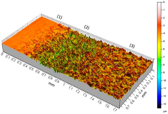
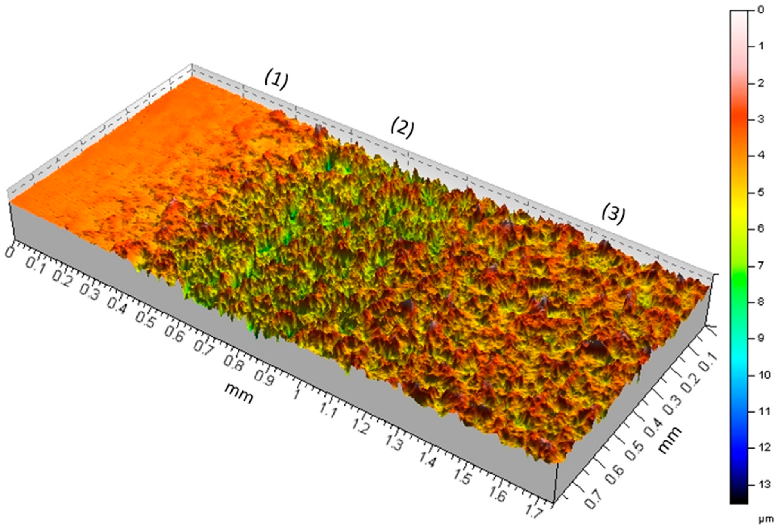
Cavitation erosion is a form of surface mechanical damage induced by the collapse of gas bubbles or bubble clouds in proximity to a solid surface [50]. This process generates rapid, transient, and repeatedly applied stresses at the material interface. The stress associated with a single bubble collapse is typically on the order of GPa [51,52,53,54], and comparable values have also been reported for ultrasonic cavitation [55]. These stresses primarily affect the near-surface layers of the material. In the present study, the depth of cavitation-induced material removal was evaluated using confocal microscopy, as illustrated by the representative image in Figure 15 for a hydrogen-charged solution-annealed sample after 5 h of exposure to cavitation erosion.
Figure 15.
3D image from the edge of the eroded surface of a hydrogen-charged solution-annealed 316L stainless steel sample after 5 h of cavitation erosion.
The resulting erosion pattern is consistent with that reported previously [44]. In particular, a valley-shaped annular ring (region 2), approximately 0.5 mm in width, is formed, within which the maximum erosion rate is concentrated near the interface with the adjacent uneroded surface (region 1). The majority of the eroded area (approximately 88%) is occupied by region 3, which exhibits a comparatively lower damage intensity than region 2. The maximum erosion depth is estimated to reach approximately 8 µm in region 1 and about 4 µm in region 2. These values are comparable to, but do not exceed, the depth of the hydrogen-affected surface layer in the same material. Therefore, the cavitation-induced damage after 5 h of exposure appears to remain within the depth of hydrogen diffusion. Furthermore, cross-sectional analyses in Figure 10 indicate that the region affected by cavitation erosion is confined to only a few micrometers beneath the surface in the charged condition. These observations collectively support the conclusion that the mechanical impact of cavitation-induced stresses is largely restricted to the near-surface region, consistent with the localized nature of bubble collapse phenomena.
Figure 2 shows a substantial reduction of up to 80% in the cumulative mass loss of the hydrogen-charged samples compared to the uncharged condition after 5 h of cavitation erosion. This behaviour is directly associated with changes in the mechanical properties of the near-surface region induced by hydrogen diffusion. To verify this effect, hydrogen-charged specimens were also tested after 7 days of storage at room temperature. As shown in Figure 2b, the cumulative mass loss of the stored specimens was comparable to that of the uncharged specimens. Since the majority of diffusible hydrogen is expected to effuse from the near-surface region during room-temperature storage, as confirmed by the hardness measurements presented in Figure 12, the recovery of the cavitation erosion rate to the level of the uncharged specimens demonstrates that the enhancement in cavitation erosion resistance is transient and directly associated with hydrogen diffusion rather than permanent microstructural or surface chemical modifications.
The increased cavitation erosion resistance of the charged samples is consistent with the observed increase in surface hardness and strength following hydrogen charging. Although tensile testing indicated a reduction in ductility due to hydrogen, the microstructural observations of the eroded surfaces in Figure 3, Figure 4, Figure 5, Figure 6, Figure 7, Figure 8 and Figure 9 did not reveal a change in the fundamental mechanism of plastic deformation between the charged and uncharged samples. The primary difference lies in a delay in the onset of visible plastic deformation features; specifically, the emergence of grain boundaries, deformation twins, and slip bands occurs after longer cavitation exposure times in the hydrogen-charged material. The absence of clear embrittlement features on the eroded surfaces may be attributed to the high-strain-rate conditions associated with cavitation loading. The strain rates on solid surfaces subjected to bubble collapse are reported to exceed 103 s−1 [56,57], which are significantly higher than those typically encountered in conventional mechanical testing. The high strain rate and repeated transient impacts may reduce the time available for hydrogen redistribution and hydrogen-assisted damage under cavitation loading. Previous studies have reported that hydrogen embrittlement susceptibility can decrease under higher strain-rate dynamic loading [21]. Nevertheless, the observed improvement in cavitation erosion resistance of the hydrogen-charged samples suggests that hydrogen-dislocation interactions may still play a role under dynamic loading conditions. However, the dominance of very high strain-rate deformation during cavitation collapse likely limits the extent to which classical hydrogen-assisted damage mechanisms can fully develop.
The observed behaviour may be rationalized in terms of a solid-solution strengthening effect induced by diffused hydrogen atoms. However, the exact mechanism responsible for the suppression of plastic deformation requires further high-resolution characterization, such as HRTEM of the near-surface region. Hydrogen atoms may impede dislocation motion, thereby delaying the formation of dislocation pile-ups at grain boundaries. As a consequence, the initiation of plastic deformation and the associated delineation of grain boundaries are postponed. For the same reason, the development of slip bands on the eroded surfaces of the charged samples is also suppressed or delayed. Accordingly, crack initiation and subsequent material removal may be shifted to longer exposure times, which can account for the observed reduction in cavitation damage.
It is important to note that the observed improvement in the cavitation erosion resistance of the 316L samples after hydrogen charging may not represent the maximum achievable effect. The cavitation erosion tests were conducted for 5 h, in addition to the time required for sample mounting, weighing, and removal between measurements. During this period, some hydrogen may have effused from the near-surface region, as suggested by the decrease in surface hardness shown in Figure 12. Furthermore, localized transient temperature increase generated by cavitation bubble collapse [58] may accelerate hydrogen effusion from the near-surface region. Therefore, the response of the hydrogen-charged surface after 5 h of cavitation erosion may underestimate the potential effect of hydrogen on cavitation erosion resistance.
5. Conclusions
Cathodic hydrogen charging was performed on 316L stainless steel at room temperature, and its effects on the mechanical properties and cavitation erosion behavior were investigated. Based on the experimental results, the following conclusions can be drawn:
- Micro-indentation and tensile testing of thin-foil specimens demonstrated that diffusible hydrogen increases the near-surface hardness and tensile strength of 316L stainless steel. In contrast, no measurable changes were observed in bulk tensile specimens after hydrogen charging, which is attributed to the hydrogen-affected region being confined predominantly to the near-surface layer at room temperature.
- Hydrogen charging significantly enhanced the cavitation erosion resistance of both the as-received and solution-annealed specimens. For the as-received material, the cumulative mass loss after 5 h of ultrasonic cavitation erosion was reduced by approximately 80% compared with the uncharged condition.
- Hydrogen increases the resistance of the material to plastic deformation, thereby delaying slip-band formation, grain boundary deformation, crack initiation, and subsequent material removal. Furthermore, diffusible hydrogen reduced the maximum depth of cavitation-induced dislocation slip, contributing to the enhanced erosion resistance.
- The hydrogen-charged specimens tested after 7 days of storage at room temperature exhibited cavitation erosion behavior and cumulative mass loss comparable to those of the uncharged specimens. This recovery, together with the corresponding reduction in surface hardness and the similar degree of plastic deformation observed in the SEM micrographs, confirms that the improvement in cavitation erosion resistance is reversible and originates from the presence of diffusible hydrogen rather than from permanent microstructural changes or surface chemical modifications.
Author Contributions
Conceptualization, M.A. and S.H.; methodology, M.A.; validation, M.A. and S.H.; investigation, M.A.; data curation, M.A.; writing—original draft preparation, M.A.; writing—review and editing, S.H.; supervision, M.A. and S.H.; project administration, M.A. and S.H.; funding acquisition, M.A. and S.H. All authors have read and agreed to the published version of the manuscript.
Funding
This research received no external funding.
Data Availability Statement
Data will be made available on request.
Acknowledgments
We would like to thank all staff at the Chair of Materials Science and Engineering, University of Duisburg-Essen, for their valuable support and assistance. Special thanks are extended to Akashkumar Sondagar and Marius Josef Hennecke for their dedicated efforts in conducting the experiments.
Conflicts of Interest
The authors declare no conflicts of interest.
References
- Dwivedi, S.K.; Vishwakarma, M. Hydrogen embrittlement in different materials: A review. Int. J. Hydrogen Energy 2018, 43, 21603–21616. [Google Scholar] [CrossRef] [Scilit]
- de Carvalho Paes Loureiro, R.; Cardoso, J.L.; Da Silva Lima, M.N.; Béreš, M.; Masoumi, M.; Maior Tavares, S.S.; de Abreu, H.F.G. Hydrogen-enhanced localized plasticity in pearlitic steel exposed to H2S: A crystallographic and fracture mechanics study. Eng. Fail. Anal. 2025, 181, 109926. [Google Scholar] [CrossRef] [Scilit]
- Yamada, K.; Koyama, M.; Kaneko, T.; Tsuzaki, K. Positive and negative effects of hydrogen on tensile behavior in polycrystalline Fe–30Mn–(6-x)Si–xAl austenitic alloys. Scr. Mater. 2015, 105, 54–57. [Google Scholar] [CrossRef] [Scilit]
- Tan, Q.; He, S.; Chen, X.; Liu, Y.; Gorbatov, O.I.; Peng, P. Hydrogen-enhanced decohesion mechanism of the Ni-Ni3X interfaces in precipitation-hardened Ni-based alloys. J. Alloys Compd. 2023, 963, 171186. [Google Scholar] [CrossRef] [Scilit]
- Ito, T.; Ogawa, Y.; Gong, W.; Mao, W.; Kawasaki, T.; Okada, K.; Shibata, A.; Harjo, S. Role of solute hydrogen on mechanical property enhancement in Fe–24Cr–19Ni austenitic steel: An in situ neutron diffraction study. Acta Mater. 2025, 287, 120767. [Google Scholar] [CrossRef] [Scilit]
- Liu, Q.; Zhou, Q.; Venezuela, J.; Zhang, M.; Atrens, A. Hydrogen influence on some advanced high-strength steels. Corros. Sci. 2017, 125, 114–138. [Google Scholar] [CrossRef] [Scilit]
- Zhu, X.; Li, W.; Zhao, H.; Wang, L.; Jin, X. Hydrogen trapping sites and hydrogen-induced cracking in high strength quenching & partitioning (Q&P) treated steel. Int. J. Hydrogen Energy 2014, 39, 13031–13040. [Google Scholar] [CrossRef] [Scilit]
- Macoretta, G.; Belardini, C.M.; Monelli, B.D.; Valentini, R.; Palmieri, M.E.; Villa, M.; Tricarico, L.; Bruschi, S.; Tedesco, M.M. Effects of hydrogen on the mechanical properties of QP1180 AHSS. Procedia Struct. Integr. 2026, 79, 508–516. [Google Scholar] [CrossRef] [Scilit]
- Adasooriya, N.D.; Tucho, W.M.; Holm, E.; Årthun, T.; Hansen, V.; Solheim, K.G.; Hemmingsen, T. Effect of hydrogen on mechanical properties and fracture of martensitic carbon steel under quenched and tempered conditions. Mater. Sci. Eng. A 2021, 803, 140495. [Google Scholar] [CrossRef] [Scilit]
- Gavriljuk, V.G.; Shivanyuk, V.N.; Foct, J. Diagnostic experimental results on the hydrogen embrittlement of austenitic steels. Acta Mater. 2003, 51, 1293–1305. [Google Scholar] [CrossRef] [Scilit]
- Nishida, H.; Ogawa, Y.; Shibata, A. Distinct impacts of hydrogen and carbon on thermally activated dislocation motion in Fe-Cr-Ni austenitic steel. Scr. Mater. 2026, 273, 117111. [Google Scholar] [CrossRef] [Scilit]
- San Marchi, C.; Somerday, B.P.; Tang, X.; Schiroky, G.H. Effects of alloy composition and strain hardening on tensile fracture of hydrogen-precharged type 316 stainless steels. Int. J. Hydrogen Energy 2008, 33, 889–904. [Google Scholar] [CrossRef] [Scilit]
- Murakami, Y.; Kanezaki, T.; Mine, Y. Hydrogen Effect against Hydrogen Embrittlement. Met. Mater. Trans. A 2010, 41, 2548–2562. [Google Scholar] [CrossRef] [Scilit]
- Ogawa, Y.; Hosoi, H.; Tsuzaki, K.; Redarce, T.; Takakuwa, O.; Matsunaga, H. Hydrogen, as an alloying element, enables a greater strength-ductility balance in an Fe-Cr-Ni-based, stable austenitic stainless steel. Acta Mater. 2020, 199, 181–192. [Google Scholar] [CrossRef] [Scilit]
- Lai, Z.-H.; Lin, Y.-T.; Sun, Y.-H.; Tu, J.-F.; Yen, H.-W. Hydrogen-induced ductilization in a novel austenitic lightweight TWIP steel. Scr. Mater. 2022, 213, 114629. [Google Scholar] [CrossRef] [Scilit]
- Khanchandani, H.; Ponge, D.; Zaefferer, S.; Gault, B. Hydrogen-induced hardening of a high-manganese twinning induced plasticity steel. Materialia 2023, 28, 101776. [Google Scholar] [CrossRef] [Scilit]
- Takakuwa, O.; Mano, Y.; Soyama, H. Increase in the local yield stress near surface of austenitic stainless steel due to invasion by hydrogen. Int. J. Hydrogen Energy 2014, 39, 6095–6103. [Google Scholar] [CrossRef] [Scilit]
- Ogawa, Y.; Fujita, T. Solid solution-hardening by hydrogen in Fe–Cr–Ni-based austenitic steel studied by strain rate sensitivity measurement: Contributions of effective stress and solute drag. Mater. Sci. Eng. A 2024, 911, 146941. [Google Scholar] [CrossRef] [Scilit]
- Gutiérrez-Urrutia, I.; Ogawa, Y.; Shibata, A. Study of the influence of hydrogen on strain hardening and strain localization in a Fe-19Ni-24Cr austenitic steel through quantitative dislocation structure analysis. Acta Mater. 2026, 309, 122078. [Google Scholar] [CrossRef] [Scilit]
- Abraham, D.P.; Altstetter, C.J. The effect of hydrogen on the yield and flow stress of an austenitic stainless steel. Metall. Mater. Trans. A 1995, 26, 2849–2858. [Google Scholar] [CrossRef] [Scilit]
- Depover, T.; Vercruysse, F.; Elmahdy, A.; Verleysen, P.; Verbeken, K. Evaluation of the hydrogen embrittlement susceptibility in DP steel under static and dynamic tensile conditions. Int. J. Impact Eng. 2019, 123, 118–125. [Google Scholar] [CrossRef] [Scilit]
- Herms, E.; Olive, J.M.; Puiggali, M. Hydrogen embrittlement of 316L type stainless steel. Mater. Sci. Eng. A 1999, 272, 279–283. [Google Scholar] [CrossRef] [Scilit]
- Shin, S.-H.; Oh, D.-K.; Kim, S.-G.; Hwang, B. Notch tensile behavior of 304L and 316L stainless steels under in-situ and ex-situ electrochemical hydrogen charging. J. Mater. Res. Technol. 2025, 36, 9158–9167. [Google Scholar] [CrossRef] [Scilit]
- Hwang, B.-K.; Kim, H.-T.; Cha, S.-J.; Park, G.-S.; Yoon, J.-T.; Kim, J.-H.; Lee, J.-M. Comparative study of hydrogen embrittlement in 310S, 304L, and 316L stainless steels under in situ electrochemical hydrogen charging. Part 1: Experimental study. Eng. Fail. Anal. 2025, 176, 109641. [Google Scholar] [CrossRef] [Scilit]
- Li, S.-H.; Lee, D.-H.; Zhao, Y.; Ramamurty, U. Hydrogen-induced softening and embrittlement in 316L stainless steel fabricated using laser-powder bed fusion. Acta Mater. 2024, 274, 119959. [Google Scholar] [CrossRef] [Scilit]
- Toribio, J. Effects of strain rate and notch geometry on hydrogen embrittlement of AISI type 316L austenitic stainless steel. Fusion Eng. Des. 1991, 16, 377–386. [Google Scholar] [CrossRef] [Scilit]
- Zhao, C.; Deng, L.; Wu, S.; Wu, W.; Peng, Y.; Wang, X.; Jiang, Y.; Gong, J. Dual role of hydrogen in fatigue life of 316L austenitic stainless steel. Int. J. Fatigue 2025, 198, 108975. [Google Scholar] [CrossRef] [Scilit]
- Mine, Y.; Horita, Z.; Murakami, Y. Effect of hydrogen on martensite formation in austenitic stainless steels in high-pressure torsion. Acta Mater. 2009, 57, 2993–3002. [Google Scholar] [CrossRef] [Scilit]
- Bak, S.H.; Kim, S.S.; Lee, D.B. Effect of hydrogen on dislocation structure and strain-induced martensite transformation in 316L stainless steel. RSC Adv. 2017, 7, 27840–27845. [Google Scholar] [CrossRef] [Scilit]
- Kowalski, M.; Khurana, A.; Weil, M.; Igual Muñoz, A.N.; Mischler, S. Effect of hydrogen charging on the tribocorrosion performance of C45CE steel. Wear 2026, 588, 206482. [Google Scholar] [CrossRef] [Scilit]
- Falat, L.; Čiripová, L.; Petruš, O.; Puchý, V.; Petryshynets, I.; Kovaľ, K.; Džunda, R. The effects of electrochemical hydrogen charging on charpy impact toughness and dry sliding tribological behavior of AISI 316H stainless steel. Crystals 2023, 13, 1249. [Google Scholar] [CrossRef] [Scilit]
- Liu, B.; Li, W.; Xu, Y.; Nie, Y.; Jia, X.; Jin, X. The effect of hydrogen on the impact-abrasion wear behavior in nanostructured bainitic steels. Wear 2021, 486–487, 204115. [Google Scholar] [CrossRef] [Scilit]
- Abedini, M.; Lopez de Arcaute y Lozano, C.; Kostka, K.; Hanke, S. Influence of surface finishing by grinding on the cavitation erosion resistance of 316L and NiAl-bronze. Wear 2024, 554, 205432. [Google Scholar] [CrossRef] [Scilit]
- Abedini, M.; Hanke, S. Superior cavitation erosion resistance of titanium through an oxygen diffusion layer. Wear 2026, 591, 206606. [Google Scholar] [CrossRef] [Scilit]
- Da Silva, F.J.; Marinho, R.R.; Paes, M.; Franco, S.D. Cavitation erosion behavior of ion-nitrided 34 CrAlNi 7 steel with different microstructures. Wear 2013, 304, 183–190. [Google Scholar] [CrossRef] [Scilit]
- Krella, A.K.; Ratajski, J. The influence of plasma nitriding on the resistance of X20Cr13 steel to cavitation erosion. Wear 2025, 564–565, 205757. [Google Scholar] [CrossRef] [Scilit]
- Severo, F.D.S.; Scheuer, C.J.; Cardoso, R.P.; Brunatto, S.F. Cavitation erosion resistance enhancement of martensitic stainless steel via low-temperature plasma carburizing. Wear 2019, 428–429, 162–166. [Google Scholar] [CrossRef] [Scilit]
- Saenz-Betancourt, C.C.; Rodríguez, S.A.; Coronado, J.J. Effect of boronising on the cavitation erosion resistance of stainless steel used for hydromachinery applications. Wear 2022, 498–499, 204330. [Google Scholar] [CrossRef] [Scilit]
- Shi, Y.T.; Cui, Z.D.; Yuan, X.B.; Yang, X.J. Effects of Boriding on Cavitation Erosion Resistance of Ti6Al4V Alloy. Key Eng. Mater. 2013, 573, 61–67. [Google Scholar] [CrossRef] [Scilit]
- ASTM E8; Standard Test Methods for Tension Testing of Metallic Materials. ASTM International: West Conshohocken, PA, USA, 2008.
- ASTM E345; Standard Test Methods of Tension Testing of Metallic Foil. ASTM International: West Conshohocken, PA, USA, 2008.
- Cara, V.; Abedini, M.; Hanke, S. Microstructural control of cavitation erosion in 316L stainless steel: Roles of grain size and grain boundary character. Wear 2026, 602, 206863. [Google Scholar] [CrossRef] [Scilit]
- ASTM G32; Standard Test Method for Cavitation Erosion Using Vibratory Apparatus. ASTM International: West Conshohocken, PA, USA, 2009.
- Paolantonio, M.; Hanke, S. Damage mechanisms in cavitation erosion of nitrogen-containing austenitic steels in 3.5% NaCl solution. Wear 2021, 464–465, 203526. [Google Scholar] [CrossRef] [Scilit]
- Abedini, M.; Hanke, S. On the reasons for reduced cavitation erosion of alloys in water containing SDS and NaCl. Wear 2025, 571, 205792. [Google Scholar] [CrossRef] [Scilit]
- Ortolland, V.; Martin, F.; Auzoux, Q.; Wolski, K. Experimental study of the hydrogen-microstructure interactions in a pre-strained 316L austenitic stainless steel. Int. J. Hydrogen Energy 2024, 67, 577–591. [Google Scholar] [CrossRef] [Scilit]
- Yun, H.S.; Jeon, S.K.; Lee, Y.-K.; Park, J.S.; Nahm, S.H. Effect of precharging methods on the hydrogen embrittlement of 304 stainless steel. Int. J. Hydrogen Energy 2024, 50, 175–188. [Google Scholar] [CrossRef] [Scilit]
- Yuan, W.J.; Zhang, Z.L.; Su, Y.J.; Qiao, L.J.; Chu, W.Y. Influence of specimen thickness with rectangular cross-section on the tensile properties of structural steels. Mater. Sci. Eng. A 2012, 532, 601–605. [Google Scholar] [CrossRef] [Scilit]
- Fu, L.; Schiralli, M.; Vedani, M.; Olofsson, J.; Górny, M.; Govahi, P.; Donnini, R.; Losurdo, M.; Angella, G. Effects of Tensile Specimen Geometry and Gripping System on the Mechanical Stability of Ausferrite in Austempered Ductile Irons. Materials 2025, 18, 4359. [Google Scholar] [CrossRef] [Scilit] [PubMed]
- Abedini, M.; Reuter, F.; Hanke, S. Corrosion and material alterations of a CuZn38Pb3 brass under acoustic cavitation. Ultrason. Sonochem. 2019, 58, 104628. [Google Scholar] [CrossRef] [Scilit] [PubMed]
- Dular, M.; Požar, T.; Zevnik, J.; Petkovšek, R. High speed observation of damage created by a collapse of a single cavitation bubble. Wear 2019, 418–419, 13–23. [Google Scholar] [CrossRef] [Scilit]
- Iga, Y.; Sasaki, H. Relationship between a non-spherical collapse of a bubble and a stress state inside a wall. Phys. Fluids 2023, 35, 023312. [Google Scholar] [CrossRef] [Scilit]
- Tzanakis, I.; Eskin, D.G.; Georgoulas, A.; Fytanidis, D.K. Incubation pit analysis and calculation of the hydrodynamic impact pressure from the implosion of an acoustic cavitation bubble. Ultrason. Sonochem. 2014, 21, 866–878. [Google Scholar] [CrossRef] [Scilit] [PubMed]
- Brujan, E.A.; Ikeda, T.; Yoshinaka, K.; Matsumoto, Y. The final stage of the collapse of a cloud of bubbles close to a rigid boundary. Ultrason. Sonochem. 2011, 18, 59–64. [Google Scholar] [CrossRef] [Scilit] [PubMed]
- Roy, S.C.; Franc, J.-P.; Pellone, C.; Fivel, M. Determination of cavitation load spectra—Part 1: Static finite element approach. Wear 2015, 344–345, 110–119. [Google Scholar] [CrossRef] [Scilit]
- Zhang, J.; Zhu, X.; Li, J. SPH-FEM Analysis of Effect of Flow Impingement of Ultrasonic Honing Cavitation Microjet on Titanium-Tantalum Alloy Surface. Micromachines 2023, 15, 38. [Google Scholar] [CrossRef] [Scilit] [PubMed]
- Tzoumaka, A.; Yang, J.; Buyukozturk, S.; Franck, C.; Henann, D.L. Modeling high strain-rate microcavitation in soft materials: The role of material behavior in bubble dynamics. Soft Matter 2023, 19, 3895–3909. [Google Scholar] [CrossRef] [Scilit] [PubMed]
- Merouani, S.; Hamdaoui, O.; Rezgui, Y.; Guemini, M. Theoretical estimation of the temperature and pressure within collapsing acoustical bubbles. Ultrason. Sonochem. 2014, 21, 53–59. [Google Scholar] [CrossRef] [Scilit] [PubMed]

Disclaimer/Publisher’s Note: The statements, opinions and data contained in all publications are solely those of the individual author(s) and contributor(s) and not of MDPI and/or the editor(s). MDPI and/or the editor(s) disclaim responsibility for any injury to people or property resulting from any ideas, methods, instructions or products referred to in the content. |
© 2026 by the authors. Licensee MDPI, Basel, Switzerland. This article is an open access article distributed under the terms and conditions of the Creative Commons Attribution (CC BY) license.