


Abstract
Liquid-hydrogen fuel-cell propulsion is a promising option for reducing the climate impact of short-range aviation, but its aircraft-level feasibility depends on the concurrent integration of cryogenic storage, megawatt-class propulsion systems, and thermal management. This paper presents an integrated conceptual design and technology-sensitivity assessment of a 101-passenger liquid-hydrogen fuel-cell aircraft, targeting a 1000 nmi design range and a 2040 entry into service, framed within the European Union FAME project. A JPAD-based aircraft sizing framework is coupled with a surrogate model for cryogenic tank sizing to investigate how selected hydrogen-subsystem characteristics propagate, through mission-fuel and tank-sizing convergence loops, to configuration-level performance and compliance with top-level aircraft requirements. The storage-system trade study identifies 2.0 bar as the most favourable sampled tank venting pressure; relative to the other investigated pressure levels, this solution reduces MTOM and design-mission block fuel by up to 8.1% and 9.2%, respectively. The propulsion-architecture study selects a four-engine layout as the best compromise between one-engine-inoperative performance, spanwise structural relief, nacelle drag, and mission fuel consumption, yielding a 2.6–2.7% lower MTOM and a 3.5–3.7% lower design-mission block fuel than the two- and six-engine alternatives. A technology-sensitivity matrix spanning 51–55% fuel-cell efficiency and 60–100% cooling-line speed recovery reveals a non-linear increase in installed power, aircraft mass, and hydrogen consumption as either parameter deteriorates. For the fixed-geometry FAME baseline, the onset of multiple TLAR violations occurs as speed recovery falls through approximately the 70–80% region, depending on fuel-cell efficiency. Within the assumptions of the present model, maintaining fuel-cell efficiency at or above approximately 53% and cooling-line speed recovery above this transition region therefore represents an approximate feasibility condition.
1. Introduction
Aviation plays a central role in global mobility, economic development, and territorial connectivity, but it also contributes to climate change through carbon dioxide emissions and other non-CO2 effects. Although aviation currently accounts for a limited share of global anthropogenic CO2 emissions, the expected growth of air transport demand makes decarbonisation a major challenge for the sector [1]. In this context, the long-term objective of achieving net-zero carbon emissions by mid-century, supported by international initiatives and commitments such as those promoted by ICAO and IATA [2,3], requires the development and assessment of disruptive aircraft technologies that go beyond incremental improvements in conventional propulsion and airframe efficiency.
Hydrogen is one of the most widely investigated energy carriers for future low/zero-emission aviation. When produced from low-carbon or renewable pathways, it can enable a substantial reduction in operational climate impact, especially when used in fuel-cell-based electric propulsion systems. Compared with kerosene combustion, fuel-cells offer the possibility of converting hydrogen into electrical power with high efficiency and without direct CO2 emissions, although water emissions, contrail formation, and the overall climate impact still require careful assessment. Among the possible hydrogen storage options, liquid-hydrogen (LH2) storage is particularly attractive for aircraft applications because it combines the high gravimetric energy density of hydrogen with a higher volumetric density than compressed gaseous storage. Nevertheless, the mass and volume of the cryogenic storage system itself are widely recognised as primary feasibility drivers [4,5]. Compared with conventional hydrocarbon fuels, LH2 still suffers from low volumetric energy density, while its cryogenic temperature, boil-off behaviour, and insulation requirements introduce major integration challenges at aircraft level.
The design of liquid-hydrogen fuel-cell aircraft is therefore not only a matter of replacing a conventional propulsion system with a zero-carbon energy converter. It requires the concurrent integration of cryogenic tanks, fuel-cell stacks, air supply systems, thermal management systems, electric machines, power electronics, and the associated structural and aerodynamic installation effects. These aspects influence aircraft mass, volume allocation, centre-of-gravity position, and aerodynamic drag, producing cascading effects on installed power, mission energy consumption, and compliance with operational and regulatory constraints. For this reason, aircraft-level conceptual design methods must be able to represent the most relevant storage and propulsion-system characteristics with sufficient fidelity, while retaining the computational efficiency needed for parametric studies and technology sensitivity analyses.
Against this background, recent literature has increasingly examined the feasibility of fuel-cell-powered aircraft and the implications of using liquid hydrogen as the primary onboard energy carrier [6,7,8]. Several contributions have focused on system-level conceptual design and propulsion-architecture integration, providing useful insights into how fuel-cell systems, electric propulsion, and supporting subsystems affect aircraft-level performance. Kiley and Agarwal [9] presented a comprehensive assessment of hydrogen fuel-cell propulsion for short- to mid-range commercial aircraft, including hybrid layouts where batteries are used to assist the fuel-cells during peak power requirements. Their automated analysis toolchain enabled the evaluation of different aircraft configurations and led them to conclude that fuel-cell systems could reach technological viability and competitive efficiency by 2035. In a similar way, Waddington et al. [10] examined a single-aisle aircraft concept powered by liquid hydrogen and fuel-cells, showing that distributed electric propulsion, when combined with dedicated thermal and air-management systems, could enable performance levels comparable to those of contemporary aircraft by 2050. Their study also considered the effect of fuel-cell ageing on aircraft performance degradation. Karpuk et al. [11] provided a broader comparison between fuel-cell aircraft and hydrogen-combustion configurations for medium- and long-range commercial applications. Their results indicated that, despite higher fuel consumption and operating costs, fuel-cell aircraft could provide substantial climate benefits, particularly for long-range missions. Pustina et al. [12] developed a multidisciplinary optimisation framework for aircraft concepts based on emerging propulsion technologies, highlighting the potential advantages of hydrogen and hybrid-electric solutions for regional aviation when assessed through a high-fidelity, weight-sensitive optimisation process. Further, Proesmans and Vos [13] integrated climate-impact metrics into the conceptual design of liquid-hydrogen aircraft powered by gas turbines, showing that flying at contrail-avoidance altitudes can significantly reduce global warming potential, although with penalties in energy consumption and operating costs.
Complementary to clean-sheet aircraft-level investigations, several studies have addressed the retrofit or incremental integration of fuel-cell-based propulsion systems into existing or derivative aircraft platforms. Rischmueller et al. [14] explored the retrofit of the D328eco regional aircraft with a parallel hybrid dual-fuel architecture combining high-temperature fuel-cells and turboshaft engines. Their work focused on hybridisation strategies and payload trade-offs, supported by off-design mission analysis and environmental impact assessment. Habrard et al. [15] performed a sensitivity analysis on a retrofitted hybrid fuel-cell aircraft, investigating the interactions among thermal management system design, fuel-cell operating conditions, and aircraft-level performance. Their results showed that cruise speed, ambient conditions, and thermal management system configuration can significantly affect emissions and payload capability.
Thermal management is indeed one of the most critical aspects for megawatt-class fuel-cell aircraft, because a large fraction of the chemical energy not converted into electrical power must be rejected as heat. At the fuel-cell stack and subsystem levels, Song et al. [16] recently reviewed thermal-management architectures and temperature-control strategies for liquid-cooled low-temperature fuel-cell systems, considering both on-load and cold-start operation. Their analysis identifies temperature uniformity, low-temperature start-up, and the coupling between cooling-system operation and overall system efficiency as continuing technological challenges. Sain et al. [17] investigated the conceptual design of air and thermal management components for nacelle-integrated low-temperature proton exchange membrane fuel-cell systems, comparing different heat-exchanger layouts and showing how integration choices influence cooling performance, installation volume, and drag. Guo et al. [18] examined cooling strategies for aviation fuel-cells, including ducted radiators and outer-mold-line heat exchangers, and quantified the associated thermal loads and aerodynamic penalties. These studies underline the need to consider thermal management integration early in the aircraft design process, rather than treating it as a secondary subsystem to be added after the main aircraft sizing loop.
Liquid-hydrogen storage integration has also been widely recognised as a major aircraft-level design driver. Burschyk et al. [19] analysed liquid-hydrogen storage design trades for a short-range aircraft concept, considering insulation solutions, venting strategies, dormancy requirements, and their impact on aircraft performance. Onorato et al. [20] assessed hydrogen transport aircraft across different categories and tank integration strategies, showing that storage system choices depend strongly on aircraft size, mission requirements, and configuration constraints. Complementary structural and aircraft-level integration studies of cryogenic tanks have been reported by Gomez and Smith [21], Silberhorn et al. [22], and Huete et al. [23], while industrial concept studies such as FlyZero [24] have benchmarked liquid-hydrogen integration at vehicle level. Beyond aviation-specific applications, Li et al. [25] reviewed advanced thermal-management technologies for long-duration LH2 storage under extreme lunar conditions. The investigated solutions include variable-density and load-bearing multilayer insulation, vapor-cooled shielding, thermodynamic venting, active refrigeration, and boil-off recovery and reutilisation. Although the lunar operating environment and stationary-storage requirements differ substantially from those of an aircraft, these technologies provide a broader perspective on possible longer-term pathways. Their potential application to aviation would nevertheless require the benefits in insulation performance and hydrogen retention to be assessed against the associated mass, power demand, system complexity, and reliability penalties.
Exploratory studies on unconventional aircraft layouts also contribute to the understanding of hydrogen propulsion integration. Chung et al. [26] assessed hydrogen solid oxide fuel-cell systems combined with gas turbine propulsion for both blended-wing-body and conventional configurations, reporting significant emissions reduction potential but also relevant differences in take-off weight and system complexity. Keijzer et al. [27] demonstrated the use of multidisciplinary design optimisation for a hydrogen-powered electric vertical take-off and landing aircraft, highlighting both the design penalties associated with hydrogen storage and the improved long-range performance potential of such architectures. Palaia et al. [28] investigated a non-conventional box-wing aircraft retrofitted for liquid-hydrogen propulsion. Focusing on medium-range missions, their work compared different tank integration strategies and found that box-wing layouts may enable either increased range or high payload capability, but not both simultaneously, due to the volumetric limitations introduced by liquid-hydrogen storage.
Although fuel-cell propulsion eliminates direct carbon-dioxide and combustion-related nitrogen-oxide emissions, the electrochemical reaction produces approximately 8.94 kg of water for each kilogram of hydrogen reacted. The relatively cool and water-rich exhaust of a fuel-cell system may satisfy the thermodynamic conditions for condensation over a broader range of atmospheric conditions than conventional kerosene-engine exhausts [29]. Contrail formation should nevertheless be distinguished from persistence and climate impact: persistent contrails require ice-supersaturated atmospheric conditions, while their subsequent radiative effect depends on the number and size of the ice crystals, optical properties, lifetime, and ambient meteorology. Climatological and high-resolution modelling studies consequently show a strong dependence on altitude, latitude, season, atmospheric humidity, and plume microphysics [30,31,32]. Possible mitigation measures include avoiding ice-supersaturated regions through operational altitude or route changes and reducing exhaust water content through controlled condensation and separation. The latter may reduce contrail propensity but introduces additional mass, cooling demand, drag, and system complexity, while removing exhaust heat without a corresponding reduction in water content can increase plume supersaturation [33,34].
Overall, the available literature shows that liquid-hydrogen fuel-cell aircraft feasibility depends on several strongly coupled design drivers, including storage-system characteristics, propulsion-system architecture, and thermal-management integration. However, many studies focus on one of these aspects in isolation or investigate them under fixed aircraft assumptions. In particular, when tank mass and volume, propulsion-system characteristics, or thermal-management penalties are prescribed upstream of aircraft sizing, the feedback through which hydrogen demand modifies tank dimensions, aircraft mass and geometry, installed power, heat-rejection requirements, and ultimately hydrogen demand itself is not closed within a common iterative convergence process. A need therefore remains for conceptual design analyses that combine aircraft sizing, cryogenic-storage integration, propulsion-layout selection, and technology-sensitivity assessment within a consistent set of operational and regulatory constraints.
The present work addresses this need by presenting an integrated conceptual design of a liquid-hydrogen fuel-cell short-range aircraft developed within the Clean Aviation FAME (Fuel cell propulsion system for Aircraft Megawatt Engines) project [35]. The target aircraft is a 101-passenger configuration designed for a 1000 nmi mission and a 2040 entry-into-service (EIS) horizon. The analysis is carried out using a parametric design framework based on the JPAD aircraft-design library, coupled with a surrogate model for cryogenic-tank sizing. Storage-, propulsion-, and thermal-management-related characteristics are embedded within the mission-fuel and tank-sizing convergence loops rather than introduced as independent modules after aircraft sizing. Their effects on hydrogen demand, tank mass and volume, aircraft geometry and mass, installed power, aerodynamic drag, and performance are therefore propagated iteratively until a consistent aircraft solution is obtained. Within this coupled framework, the liquid-hydrogen storage system is first examined through a venting-pressure study; the megawatt-class fuel cells are then investigated as a configuration-level lever through the number of propulsion units. The feedback between propulsion- and thermal-management-related characteristics and aircraft sizing is finally investigated through a sensitivity analysis of fuel-cell efficiency and cooling-line speed recovery. Taken together, these analyses show how subsystem design choices and technology assumptions propagate through the coupled subsystem and aircraft sizing loops, thereby governing aircraft-level feasibility and performance margins.
The remainder of the paper is organised as follows. Section 2 presents the design methodology, including the JPAD-based conceptual design framework (Section 2.1) and the surrogate model adopted for liquid-hydrogen tank sizing (Section 2.2). The same section also introduces the LH2 powerplant-related assumptions (Section 2.3), the adopted top-level aircraft requirements (TLARs, Section 2.4), and the initial sizing configurations (Section 2.5). Section 3 presents the main results, including the storage-system venting-pressure study (Section 3.1), the propulsion-architecture optimisation (Section 3.2), the technology-effect propagation analysis under degraded fuel-cell efficiency and cooling-drag recovery assumptions (Section 3.3), and the resilience assessment of the FAME baseline configuration (Section 3.4). Finally, Section 4 discusses the main findings, limitations, and future developments.
2. Materials and Methods
2.1. JPAD-Based FAME Conceptual Design Framework
The aircraft-level analyses presented in this work are carried out using the JPAD library [36,37], a suite of tools for aircraft conceptual and preliminary design developed by the DAF research group of the University of Naples Federico II in collaboration with SmartUp Engineering. JPAD is implemented in Java according to an object-oriented and modular architecture, allowing parameterised aircraft models, disciplinary analyses, and design-space exploration procedures to be assembled within a common computational environment.
The aircraft definition is organised hierarchically and is provided through structured input files describing the configuration, geometry, systems, mission, and applicable top-level aircraft requirements. The main aircraft components—including the fuselage and cabin, lifting surfaces and airfoils, propulsion units and nacelles, landing gear, and onboard systems—are represented as interconnected parametric objects. This representation allows geometrical or technological changes introduced during the design process to be propagated consistently to the corresponding disciplinary analyses.
The JPAD environment comprises several interconnected modules. The jpad-initializer module supports the generation of a preliminary aircraft configuration from the assigned top-level requirements, aircraft category, and selected layout. The resulting aircraft model is subsequently handled by jpad-core, which contains the geometry representation and the principal analysis methods. The jpad-doe module coordinates parametric variations of selected design and technology variables, repeatedly calls the analysis modules, and organises the resulting data for sensitivity studies, response-surface generation, and subsequent optimisation.
Within jpad-core, the mass-estimation module provides a component-level Class-II mass breakdown using selectable semi-empirical methods from the aircraft-design literature. Calibration factors can be assigned to individual components to represent different technology levels. The balance module combines the estimated component masses and locations to determine the aircraft centre-of-gravity envelope and moments of inertia for the relevant loading conditions. The aerodynamic module follows a component-to-aircraft build-up approach to estimate the lift, drag, and pitching-moment characteristics in the take-off, climb, cruise, and landing configurations, including trimmed aerodynamic polars and longitudinal- and lateral-stability derivatives. The performance module uses these results to evaluate ground and airborne performance, including all-engines-operative and one-engine- inoperative conditions, climb performance and ceilings, cruise characteristics, mission performance, and payload–range capability. Phases such as take-off and landing are evaluated by numerically integrating the corresponding equations of motion.
A relevant capability of JPAD for the present study is its powerplant parameterisation, which enables the analysis of aircraft configurations based on emerging propulsion technologies such as batteries and fuel cells. The powerplant is defined through dedicated input files specifying the characteristics of power sources and power units. The modelled system may include fuel tanks, batteries, and fuel-cell systems, as well as gas turbine engines, electric motors, inverters, cables, reduction gearboxes, and propellers or fans. In the case of fuel cells and batteries, JPAD adopts a bottom-up representation starting from cell-level characteristics, from which the overall system behaviour is derived according to the selected sizing and operating assumptions, consistent with established fuel-cell system design practice for aviation [38]. The resulting parameterisation makes it possible to estimate, in a consistent way, the net output power, efficiency, mass, and volume of the main powerplant subsystems, while accounting for the contributions of auxiliaries and off-takes. This feature is particularly relevant for hydrogen-powered aircraft, whose feasibility strongly depends on the integrated treatment of storage, conversion, and propulsion subsystems.
For the FAME project, the general capabilities of JPAD have been embedded into the conceptual design framework schematically illustrated in Figure 1. The workflow is tailored to support the parametric assessment and optimisation of liquid-hydrogen fuel-cell aircraft under a prescribed set of TLARs and technology assumptions. It begins with an initialisation phase, in which a baseline aircraft is defined together with the adopted powerplant technology levels and airframe/systems technology levels. This baseline aircraft provides the starting point for the subsequent parametric update process.
Figure 1.
JPAD-based conceptual design framework tailored to the FAME aircraft. Starting from baseline aircraft initialization and technology-level assumptions, the workflow updates the aircraft geometry and propulsion system sizing, performs mission fuel and LH2 tank sizing convergence loops, and assesses the resulting configurations against the prescribed TLARs. Within the LH2 tank-sizing loop, the surrogate receives the hydrogen mass per tank, venting pressure, cruise altitude, and admissible internal-height limit, and returns the tank thickness and gravimetric index used to determine the external dimensions, volume, and mass. Repeated converged analyses are used to generate response surfaces and support aircraft-level trade-off studies and optimisation.
The aircraft update phase is driven by a set of design variables, from which a corresponding set of derived variables is obtained. In general terms, the framework can accommodate design variables related to wing sizing, wing aspect ratio, propulsion system sizing, cabin arrangement, and other configuration-level descriptors, while derived quantities may include geometric characteristics such as wing span, fuselage cross-section dimensions, fuselage central-section length, and tailplane geometry. The output of this phase is an updated aircraft configuration, consistent with the selected design variable set and with the imposed technology assumptions.
The updated aircraft is then passed to the analysis block, which performs the multidisciplinary calculations required to assess the configuration. In the present implementation, this block includes mass-breakdown estimation, centre-of-gravity calculation, aerodynamic analysis, and design-mission analysis. The latter is embedded within an iterative mission-fuel convergence loop, in which the aircraft is repeatedly re-evaluated until consistency is achieved between the assumed and computed design-mission fuel. Once this first convergence is reached, the framework activates a second iterative step related to LH2 tank sizing, ensuring consistency between the required hydrogen mass and the tank-system characteristics adopted for the configuration. If convergence is not achieved in either loop, the aircraft is revised, and the process is repeated. After the two convergence loops are satisfied, the finalised configuration undergoes a complete performance assessment, as represented in Figure 1. Although JPAD also provides cost and environmental assessment capabilities, these analyses are outside the scope of the present study and were not performed for the configurations considered herein.
For the FAME case, the aircraft-level optimisation is performed in two successive stages. First, the converged JPAD workflow is evaluated over a structured grid defined by the wing planform area, , and the gross sizing power of each fuel-cell system, . Each JPAD evaluation includes the coupled mass, aerodynamic, propulsion, mission-fuel, and LH2 tank-sizing calculations described above. The resulting database therefore contains converged values of the design-mission block fuel and of all the quantities used to assess aircraft feasibility.
A separate response surface is generated for each prescribed combination of the discrete architecture and technology parameters considered in the study, namely the number of propulsion units, tank venting pressure, fuel-cell efficiency, and cooling-line speed-recovery assumption. These quantities are therefore treated as scenario parameters rather than as continuous design variables within a single optimisation. For each scenario, the continuous design vector is
The wing planform area is bounded between 95 and 130 m2 for all the investigated configurations. The bounds imposed on the gross sizing power of each fuel-cell system depend on the number of propulsion units: 4.5–6.0 MW per unit for the two-engine configuration, 2.25–4.25 MW per unit for the four-engine configuration, and 1.5–2.0 MW per unit for the six-engine configuration. Piecewise-linear gridded interpolants are constructed in MATLAB (R2025b) for the design-mission block fuel and for each performance or feasibility quantity returned by JPAD. The lower and upper bounds of the optimisation variables correspond to the minimum and maximum values sampled in the JPAD design grid, so that the optimisation remains within the analysed design domain.
The resulting constrained optimisation problem is formulated as
where is the interpolated hydrogen block fuel required for the 1000 nmi design mission, denotes the fixed architecture and technology scenario, and represents the interpolated constraint functions. The constraints include take-off and landing field lengths; first-, second-, and fourth-segment take-off climb gradients; one-engine-inoperative (OEI) service ceiling; time to climb to cruise altitude; initial cruise altitude capability (ICAC); cruise Mach capability while maintaining a residual climb rate of 300 ft/min; maximum approach calibrated airspeed (CAS); and longitudinal static stability. The corresponding limits are defined by the applicable TLAR set; for the take-off climb-gradient constraints, the minimum required values are adjusted according to the number of installed propulsion units, in accordance with the applicable airworthiness requirements.
The problem is solved using the sequential quadratic programming algorithm of the MATLAB fmincon solver, with a nonlinear-constraint tolerance of , a maximum of 500 iterations, and a maximum of 1000 objective and constraint evaluations. The optimum is accepted only when the solver reports convergence and the residual violation of every active constraint is within the prescribed tolerance. The initial JPAD grid is therefore used to construct the aircraft-level interpolants, rather than to select the optimum directly: the optimisation searches continuously between the sampled design points while retaining the multidisciplinary couplings captured by the converged JPAD analyses.
2.2. LH2 Tank Surrogate Model
The integration of cryogenic hydrogen storage is one of the main aircraft-level design drivers for liquid-hydrogen fuel-cell configurations. In contrast with conventional fuel tanks, LH2 tanks must satisfy coupled geometrical, structural, and thermal requirements, while also complying with aircraft installation constraints and mission-level fuel demand. For this reason, JPAD is coupled with a dedicated in-house MATLAB-based tool for the sizing of cryogenic hydrogen tanks. The tool is derived from the methodology proposed by Winnefeld et al. [39] and has been further used in previous aircraft-level and tank-level studies involving liquid-hydrogen storage integration [40].
The tank sizing tool estimates the main characteristics of the storage system as a function of the required hydrogen mass, the selected mission profile, the imposed dormancy requirement, and geometrical constraints such as the tank internal diameter. The calculation accounts for both structural and thermal aspects of the tank design. In particular, the inner wall is sized according to the internal pressure level, while the external containment and insulation system are evaluated according to the selected tank architecture and operational requirements. A simplified one-dimensional thermal model is adopted to estimate the heat flow reaching the hydrogen during the mission. This formulation enables the preliminary evaluation of the main heat-transfer contributions through the tank walls and insulation layers, and supports the estimation of boil-off-related quantities and the verification of the imposed no-venting requirement. The resulting outputs include tank mass breakdown, storage-system gravimetric index, insulation thickness, structural thickness, and internal and external dimensions.
For the analyses presented in this work, the detailed tank sizing tool is used to generate a reduced-order surrogate model of the LH2 storage system. The surrogate is built from approximately 3600 detailed tank sizing simulations, in which the main varied parameters are the tank internal diameter, the maximum venting pressure, the LH2 mass to be stored, and the mission profile. The adopted mission profile includes an initial ground phase lasting 240 min under ISA+40 °C conditions, during which the tank must maintain the required dormancy without venting. The remaining tank-design assumptions are kept fixed throughout the surrogate-generation process. In particular, the insulation system is assumed to be vacuum plus multi-layer insulation, based on Dacron and double-aluminised polyester film; the vessel caps are assumed to be elliptic, with a radius equal to one quarter of the tank internal diameter; and Aluminum 2219 is adopted for the structural and stiffening elements. The trapped hydrogen mass is set equal to 10% of the total LH2 mass to be stored. The nominal mission analyses assume no unintended hydrogen losses from the storage and distribution systems; consequently, leakage is not included in the hydrogen mass balance.
The reduced-order representation of the LH2 tank was trained using a full-factorial database comprising 3570 converged tank designs. The four varying predictors were the tank internal-height limit (), design venting pressure (), hydrogen mass stored in each tank (), and cruise altitude ():
Two independent regression models were trained using the MATLAB Regression Learner app, since the aircraft-sizing workflow requires only the total radial tank thickness, including the structural walls and insulation, and the storage-system gravimetric index:
Candidate regression algorithms were evaluated using five-fold cross-validation, and the model providing the lowest validation root mean square error (RMSE) was retained for each response. A fine regression tree was selected for the total tank thickness, with an RMSE of 0.1 cm, whereas a Gaussian-process regression model employing a Matérn kernel was selected for the gravimetric index, with an RMSE of 0.18 percentage points. The corresponding range-normalized RMSE values are 0.58% and 0.91%, respectively. The training ranges and model-performance metrics are summarised in Table 1.
Table 1.
Training domain and validation performance of the LH2 tank surrogate models.
At each aircraft-sizing iteration, JPAD supplies the hydrogen mass per tank, the selected venting pressure, and the design cruise altitude. The fuselage installation envelope, after accounting for the prescribed clearances and margins for the crash structure, fittings, and tank subsystems, determines the admissible internal-height limit. The predicted total thickness is used to derive the external tank dimensions and volume, while the predicted gravimetric index determines the tank mass. In particular,
where is expressed as a fraction. These derived quantities are then returned to the coupled aircraft-sizing loop.
Within this framework, the present study does not perform a down-selection among alternative hydrogen-storage technologies. Cryogenic liquid-hydrogen storage with vacuum and multi-layer insulation is prescribed by the reference propulsion and aircraft architecture developed within the FAME project and is therefore retained as the technological basis of the analysis. This selection is consistent with aircraft-level studies and industrial roadmaps addressing hydrogen-powered regional and short-range commercial aircraft, for which the storage-system mass and the volumetric integration of the required hydrogen quantity represent major design drivers [6,19,20,24]. Compressed-gaseous storage was not retained because its lower volumetric storage density and high-pressure vessel mass would introduce substantial penalties for a 101-passenger, 1000 nmi aircraft. Foam-insulated cryogenic tanks can be lighter and simpler, but their higher heat ingress makes the prescribed 240 min no-vent dormancy requirement at ISA+40 °C more difficult to satisfy [19]. Onboard hydrogen generation is also an investigated research topic [41]; however, it would still require a hydrogen-storage or buffer system, in addition to another primary energy source and the associated conversion equipment. The analysis therefore focuses on the aircraft-level effects of the selected cryogenic storage technology.
2.3. Powerplant-Related Assumptions
The propulsion architecture adopted in this work is based on liquid-hydrogen fuel-cell electric propulsion. A schematic representation of the powerplant layout is provided in Figure 2, while the main technology assumptions used in the aircraft-level analyses are summarised in Table 2. The architecture is centred on a cryogenic LH2 storage system supplying multiple fuel-cell engines installed in wing-mounted nacelles. Each complete fuel-cell engine comprises a fuel-cell system (FCS), an air-supply line (ASL), a cooling line (CL), an electrical power line (PL), and a propeller. In the terminology adopted in this work, the FCS refers exclusively to the assembly of fuel-cell stacks operating in parallel; the ASL, CL, and PL are treated as separate subsystems. This modular arrangement provides scalability at megawatt power levels and supports the assessment of different propulsion layouts.
Figure 2.
Schematic representation of the FAME liquid-hydrogen fuel-cell powerplant architecture, showing the aft-fuselage LH2 storage system, the wing-mounted power units, and the main nacelle-level components: reduction gearbox (GB), electric motor and inverter (EM), fuel-cell system (FCS), air supply line (ASL), and cooling line (CL).
Table 2.
Powerplant technology assumptions adopted in the aircraft-level analyses.
The numerical values adopted here are project-level technology assumptions defined within FAME for a 2035 technology freeze and a 2040 EIS, rather than correlations fitted to a single public hardware database. Within JPAD, component mass and volume are obtained through direct scaling with the corresponding sizing quantity and gravimetric or volumetric power density, while component efficiencies and auxiliary-power extractions are applied sequentially along the power-conversion chain. For the cooling system, the relevant sizing quantity is the heat-rejection load derived from the FCS power and efficiency.
The fuel-cell technology targeted within the FAME project is based on intermediate-temperature proton-exchange-membrane fuel cells (IT-PEMFCs), with a nominal operating temperature of approximately 120 °C. The FCS technology level is characterised by gravimetric and volumetric power densities of 2.0 kW/kg and 2.0 kW/L, respectively. These values apply exclusively to the fuel-cell stack assembly and are used to estimate its mass and volume as functions of the gross FCS sizing power. Fuel-cell efficiency is defined as the ratio between the gross direct-current (DC) electrical power generated by the FCS and the chemical power associated with the hydrogen consumption, evaluated on a lower-heating-value (LHV) basis. It is assumed to vary from 55.0% at maximum power to 65.0% at minimum power, the latter corresponding to 10% of the rated power. The gross FCS power is defined upstream of the power consumed by the air-supply and cooling systems and of the downstream power-line losses. A nominal DC voltage of 850 V is adopted. The heat rejected by the FCS is estimated from the fuel-cell efficiency, with 10.0% of the generated heat assumed to be removed through the exhaust, while the remaining fraction is assigned to the cooling system. This representation provides a simplified but consistent way to link fuel-cell efficiency, cooling requirements, subsystem mass, and aircraft-level performance.
The reactant air required by the fuel cells is provided through an ASL, which includes a compressor to compensate for pressure losses and to ensure adequate fuel-cell operation over the aircraft flight envelope. In parallel, the heat generated by the fuel-cell electrochemical conversion process is rejected through a dedicated CL, including one or more heat exchangers. The ASL and CL are therefore treated as integral parts of the fuel-cell propulsion system, since they directly affect both mass and available propulsive power. In the present conceptual design implementation, their effect on power availability is represented through altitude-dependent power extractions from the FCS. These losses are assumed to increase approximately linearly from 8.0% of the FCS power at sea-level ISA conditions to 19.0% at 8500 m ISA conditions; for higher altitudes, the same trend is extrapolated.
The net electrical power remaining after the ASL and CL extractions is transmitted to the propeller through the PL, which comprises the inverter, electric motor, cables, and reduction gearbox. The electric motor, inverter, and cables are represented through an equivalent gravimetric power density of 5.0 kW/kg. The motor and inverter efficiencies are assumed to be 96.0% and 99.0%, respectively, while the cable and gearbox efficiencies are set to 99.5% and 99.4%. These contributions are combined within the aircraft model to determine the mechanical power available at the propeller from the gross FCS sizing power. Consistently with the component boundaries defined above, the mass of the complete fuel-cell engine is obtained by combining the separately estimated contributions of the FCS, ASL, CL, PL, and propeller.
The LH2 storage assumptions are consistent with the tank-sizing approach described in Section 2.2. Hydrogen is modelled with a LHV of 33.3 kWh/kg, and two cryogenic tanks are considered. The tank system is required to satisfy a 240 min dormancy condition under ISA+40 °C without venting, and a vacuum plus multi-layer insulation concept is adopted. The corresponding tank mass and dimensions are not imposed directly in the aircraft model, but are estimated through the tank surrogate model as a function of the required hydrogen mass, operational envelope, and selected tank-design parameters.
Finally, the aircraft is assumed to require a constant non-propulsive power demand of 200 kW, representative of onboard systems and auxiliary loads. This demand is equally distributed among the installed propulsion units and is subtracted from the power available for propulsion.
To provide a technology-level context for the assumptions summarised in Table 2, Table 3 presents an illustrative comparison between the 2.5 MW-class liquid-hydrogen fuel-cell-electric power unit adopted for the FAME baseline and an advanced conventional gas-turbine propeller engine representative of the same 2040 EIS horizon, assuming a technology freeze in 2035. The two propulsion systems are evaluated under the same representative maximum take-off operating condition and are selected to provide comparable power at the propeller shaft. The comparison covers the energy-conversion chain from the chemical energy of the onboard fuel to the mechanical power delivered to the propeller. For the fuel-cell architecture, this includes the fuel-cell system and its air-supply and cooling auxiliaries, inverter, electric motor, cables, and reduction gearbox; for the conventional architecture, it includes the gas-turbine engine, its relevant accessories and power extractions, and the reduction gearbox. All conversion efficiencies are expressed consistently on a LHV basis. The corresponding propulsion-system masses are also reported using equivalent system boundaries. This comparison is intended to illustrate the different efficiency and mass characteristics of the two propulsion chains and does not constitute a complete aircraft-level comparison, which would additionally require consideration of fuel-storage mass and volume, aerodynamic installation effects, and mission-dependent performance.
Table 3.
Illustrative comparison between a fuel-cell engine incorporating a 2.5 MW FCS based on FAME technology assumptions and an equivalent advanced gas-turbine engine at the reference maximum take-off condition.
2.4. Top-Level Aircraft Requirements
The TLARs adopted for the design, summarised in Table 4, were defined within the FAME project to represent a feasible yet ambitious performance envelope for a fully electric, liquid-hydrogen fuel-cell short-range aircraft. The EIS horizon sets the technological reference, particularly for the propulsion and energy-storage systems. The design mission specifies a 1000 nmi range and 101 passengers at an average mass of 95 kg, with a cruise Mach number of 0.55, targeting a higher-capacity and longer-range segment than current-generation short-range turboprops. Operational and regulatory constraints are embedded directly in the requirement set: a take-off field length not exceeding 1400 m at sea level (SL) under ISA+15 °C at maximum take-off mass (MTOM), a landing field length below 1400 m at maximum landing mass (MLM) under the same conditions, compliance with aircraft Design Group III (wing span between 24 and 36 m), and Approach Category C or lower (approach CAS below 141 kt). At the present conceptual-design level, the approach CAS is estimated as 1.23 times landing stall speed, evaluated at MLM. Since an independent structural estimate of the MLM is not yet available, the latter is conservatively assumed equal to the MTOM (this assumption is also consistent with the comparatively small hydrogen-fuel mass fraction of the aircraft). High-altitude operability is supported by a take-off altitude capability up to 14,600 ft and a OEI ceiling above 10,000 ft, while an ICAC of 27,000 ft with a minimum rate of climb of 300 ft/min is required. An additional in-house constraint limiting the time to reach flight level (FL) 270 to less than 25 min is imposed to ensure competitive mission performance. The mission profile accommodates standard commercial reserves: 100 nmi diversion, 30 min holding, and 5% contingency fuel. The same requirement set is used both to constrain the admissible design space and, as feasibility criteria, to guide the selection of the preferred configuration in Section 3.
Table 4.
Top-level aircraft requirements adopted for the conceptual design of the FAME aircraft.
2.5. Initial Sizing Configurations
Using the statistical pre-design tool integrated within the JPAD environment, three initial aircraft configurations were generated on the basis of the TLARs reported in Table 4 and of the powerplant technology assumptions summarised in Table 2. The three configurations correspond to the propulsion layouts investigated in this work, namely aircraft equipped with two, four, or six wing-mounted fuel-cell propulsion units. The statistical pre-design process uses the prescribed TLARs as input and derives plausible starting configurations by relying on correlations obtained from existing aircraft with comparable performance levels, payload capacity, and mission requirements. These initial aircraft are then used as baseline geometries for the subsequent optimisation studies.
After their initial generation, the three starting configurations were manually adapted to incorporate a preliminary LH2 storage system located in the aft fuselage, downstream of the rear pressure bulkhead. All configurations share the same general arrangement: a high-wing layout, a T-tail empennage, podded wing-mounted propeller-driven propulsion units, and a main landing gear housed in a fairing below the fuselage. The fuselage cross-section and cabin arrangement are kept common across the three propulsion layouts. The main shared fuselage and cabin characteristics are summarised in Table 5. These values define the common starting platform used in the analyses; subsequent variations associated with LH2 tank sizing and aircraft optimisation are handled within the design framework described in Section 2.1. A representative view of the four-engine configuration is provided in Figure 3.
Table 5.
Fuselage and cabin characteristics common to the initial aircraft configurations.
Figure 3.
Representative views of the starting four-engine aircraft configuration, showing the high-wing layout, T-tail empennage, and wing-mounted fuel-cell propulsion units.
Considering the targeted 2040 EIS, technology correction factors were applied to the semi-empirical models embedded in JPAD, which are originally calibrated for regional and short-range propeller-driven aircraft. In particular, correction factors ranging from 85% to 90% were introduced in the estimation of structural and interior masses, reflecting expected improvements in materials, structural design, and lightweight cabin systems. Similarly, reduction was applied to the estimation of excrescence and interference drag contributions, accounting for the assumed aerodynamic improvements of a future clean-sheet configuration compared with current-generation regional aircraft.
Unless otherwise specified, the studies presented in the following do not include the additional aerodynamic drag associated with the integration of the fuel-cell cooling system. This contribution is treated separately in the technology sensitivity analysis presented in Section 3.3 and Section 3.4, where different levels of cooling-drag recovery are investigated to assess the robustness of the baseline FAME concept to thermal-management integration penalties.
Throughout the parametric analyses, the wing span is fixed at 35.95 m, slightly below the 36 m upper limit associated with Group III, whereas the wing planform area is treated as a design variable. The corresponding wing aspect ratio is consequently derived.
3. Results
The following sections present the aircraft-level outcomes of the coupled sizing framework described in Section 2. The results are organised to expose how selected hydrogen-subsystem characteristics propagate, through the mission-fuel and tank-sizing convergence loops, into configuration-level effects. Section 3.1 isolates the liquid-hydrogen storage system through a tank venting-pressure study, while Section 3.2 addresses the integration of the megawatt-class fuel-cell propulsion units through the propulsion-architecture optimisation. Section 3.3 then examines how degraded fuel-cell efficiency and incomplete cooling-drag recovery affect the optimised aircraft, reshaping the feasible design envelope and defining practical feasibility boundaries. Finally, Section 3.4 assesses the residual resilience of the FAME baseline configuration, whose wing area and installed power are intentionally increased with respect to the minimum-fuel optimum to provide margin against subsystem-performance deviations and thermal-management integration penalties.
3.1. LH2 Tank Venting-Pressure Trade Study
The first design driver examined is the cryogenic storage system, whose gravimetric performance directly conditions the hydrogen mass that must be carried and, through it, the entire aircraft sizing chain. The analysis is conducted with the surrogate tank model of Section 2.2 applied to the four-engine reference platform, and focuses on the maximum tank venting pressure as the single storage parameter that most strongly governs the structural-versus-insulation balance of the vessel. Four venting-pressure levels are investigated—1.5, 2.0, 2.5, and 3.0 bar—and for each level a dedicated optimisation is performed over the wing planform area and the individual FCS gross power, minimising the block fuel required for the 1000 nmi design mission while satisfying the full set of TLARs. The minimum-block-fuel aircraft obtained for each sampled pressure level is reported in Table 6, and the corresponding trends are summarised in Figure 4.
Table 6.
Characteristics of the minimum-block-fuel aircraft designs obtained for the investigated LH2 tank venting pressures.
Figure 4.
Effect of LH2 tank venting pressure on tank-level and aircraft-level quantities, normalized with respect to the 2.0 bar case. Panel (a) compares the relative variation of tank total thickness and tank gravimetric index. Panel (b) shows the corresponding aircraft-level impact in terms of MTOM and design-mission block fuel.
The venting pressure acts on the tank through two competing mechanisms. Increasing the allowable pressure reduces the insulation requirement and the total wall thickness—most markedly between 1.5 and 2.0 bar—which yields shorter tanks and a more compact rear fuselage. At the same time, the higher internal pressure raises the structural demand on the inner wall and stiffeners. The net result is a tank gravimetric index that improves sharply up to 2.0 bar and then deteriorates as the structural penalty begins to outweigh the insulation savings. Crucially, this storage-level behaviour does not remain local: beyond 2.0 bar the declining gravimetric index increases the sizing hydrogen mass, which in turn enlarges the tank, raises the maximum take-off mass, and forces a higher installed power to preserve performance compliance. This cascade—hereafter referred to as the storage snowball effect—is the central reason why the storage system must be sized inside, and not upstream of, the aircraft convergence loop.
Among the four sampled pressure levels, the 2.0 bar case provides the most favourable compromise. At this setting the configuration attains the lowest MTOM (44,864 kg), the lowest total installed gross power (9419 kW), the lowest block fuel (1181.6 kg on the design mission and 328.1 kg on a representative 250 nmi mission), and a compact fuselage (37.23 m). The 1.5 bar case suffers from a heavy, thick tank (sizing hydrogen mass of 1722.8 kg and MTOM of 48,839 kg), whereas the 2.5 and 3.0 bar cases, despite a marginally shorter fuselage, are penalised by the snowball effect on hydrogen mass and installed gross power. The 2.0 bar setting is therefore retained for all subsequent analyses.
Nevertheless, it should be noted that this value is selected from a discrete aircraft-level venting-pressure trade study, mainly driven by tank mass, volume, and integration effects. At this stage, the tank pressure selection does not explicitly account for additional constraints associated with refuelling operations or with the pressure levels required by the hydrogen distribution system to supply the fuel-cell system. Including these aspects in the optimisation could shift the preferred tank operating and venting pressure toward different, potentially higher, values. This would modify the balance between thermal and structural requirements: higher pressure levels may reduce part of the insulation-related penalty and support hydrogen delivery, but they also increase the structural demand on the tank walls and stiffening elements. As a consequence, the storage-system gravimetric index and the resulting aircraft-level optimum may differ from those obtained in the present preliminary analysis.
3.2. Propulsion Architecture Optimisation
The second design driver concerns the integration of the megawatt-class fuel-cell propulsion system. Because the FCS is modular and scalable, the total installed power can be distributed across a different number of wing-mounted nacelles without altering the underlying technology assumptions. This freedom couples two opposing aircraft-level effects that are specific to a distributed fuel-cell layout: spreading the propulsion mass along the span relieves the wing structure, while adding nacelles increases parasitic and interference drag. The number of fuel-cell units is therefore not a propulsion-only choice, but a configuration-level lever acting simultaneously on structural mass and aerodynamics. Moreover, the selected number of propulsion units directly affects redundancy. In an OEI condition, a two-engine aircraft loses one half of its propulsion units, whereas four- and six-engine layouts lose only one quarter and one sixth, respectively.
Three layouts—two, four, and six wing-mounted units, each fed by an independent FCS—are assessed at the fixed 2.0 bar venting pressure selected as the best-performing sampled value in Section 3.1. For each layout, the wing planform area and the individual FCS sizing power are optimised to minimise the design-mission block fuel under the TLARs. The block-fuel contour maps with the active constraints bounding the feasible region are reported in Figure 5, Figure 6 and Figure 7, and the optimal solutions are compared in Table 7.
Figure 5.
Design-mission block-fuel contour plot for the two-engine configuration. Only constraints intersecting the displayed design domains are shown.
Figure 6.
Design-mission block-fuel contour plot for the four-engine configuration. Only constraints intersecting the displayed design domains are shown.
Figure 7.
Design-mission block-fuel contour plot for the six-engine configuration. Only constraints intersecting the displayed design domains are shown.
Table 7.
Characteristics of the minimum-block-fuel aircraft designs obtained for the investigated numbers of fuel-cell propulsion units.
The two-engine layout is strongly constrained by one-engine-inoperative take-off performance and time to climb to cruise altitude, which drive the individual FCS power above 5 MW and the wing area larger than 110 m2. Although fewer nacelles reduce parasitic drag, the large and heavy stacks raise the MTOM to 46,130 kg and the block fuel to 1227.1 kg, eroding overall efficiency. The six-engine layout is governed by essentially the same constraints as the four-engine one, but pays the largest aerodynamic penalty, with the highest clean drag-area product (2.87 m2) and a block fuel of 1224.9 kg, despite offering the greatest redundancy and OEI ceiling.
The four-engine layout emerges as the most balanced solution. The required power per nacelle drops to about 2.35 MW and the optimal wing area is reduced by roughly 10 m2 relative to the two-engine case, giving the lowest installed power (9419 kW) and the lowest MTOM (44,864 kg) of all layouts. The distribution of the propulsion masses along the wing produces a measurable reduction in root bending moment and hence in structural mass, while the aerodynamic configuration remains favourable, with the lowest clean drag-area product (2.77 m2). The combination yields the lowest block fuel (1181.6 kg on the design mission and 328.1 kg on the 250 nmi mission). The four-engine architecture is therefore adopted for the reference concept.
3.3. Technology-Effect Propagation Under Degraded Subsystem Assumptions
The previous sections identified the storage-system venting pressure and the number of fuel-cell propulsion units as two configuration-level drivers for the aircraft sizing process. The final step of the analysis investigates how deviations in selected propulsion- and thermal-management-related assumptions propagate through the same coupled sizing loop. Two parameters are considered: the gross stack efficiency at maximum power and the speed recovery at the outlet of the cooling-line duct.
The first parameter directly affects the amount of hydrogen required to generate a given electrical power and the fraction of chemical energy rejected as heat. A reduction in fuel-cell efficiency therefore produces a dual penalty: it increases the hydrogen mass required for the mission and simultaneously increases the thermal load to be rejected by the cooling system. From a lifecycle-design perspective, relying exclusively on beginning-of-life fuel-cell performance may overestimate the capability available throughout aircraft operation. Aircraft sizing should therefore also be assessed against a degraded or minimum guaranteed performance level representative of the intended end-of-life condition or scheduled stack-replacement interval. Meng et al. [42] demonstrated that Transformer-based prognostics can predict PEMFC voltage-degradation trends, providing a potential data-driven basis for defining lifecycle-dependent performance assumptions. For systems comprising multiple parallel stacks, the resulting state-of-health information may also support degradation-aware power allocation. In this respect, Mei et al. [43] showed, for a multi-stack commercial-vehicle application, that incorporating state-of-health disparity into the energy-management objective can mitigate the imbalance among stacks and reduce system degradation. Although such a strategy would require aerospace-specific adaptation and validation, it indicates that the minimum performance available throughout the operating life depends on both intrinsic stack degradation and the adopted energy-management strategy. The present study does not model a time-dependent ageing trajectory or explicitly resolve the direct electrochemical effects of vibration, thermal cycling, humidity, pressure and temperature variations, or repeated load cycles. Consequently, the investigated maximum-power gross stack-efficiency values, from 55% to 51%, are treated as parametric technology or degraded-performance scenarios rather than as predictions associated with specific operating ages or environmental-exposure levels.
The second parameter represents the aerodynamic effectiveness of the cooling-line integration. For each propulsion unit, the thermal power generated by the FCS is calculated from its gross DC sizing power, , and its LHV-based electrical efficiency, . The corresponding hydrogen chemical-input power and waste-heat rate are
Consistently with the assumptions reported in Table 2, 10% of this heat is assumed to be removed through the FCS exhaust. Consequently, the heat load assigned to the cooling line is
The required cooling-air mass flow rate is then estimated through a simplified heat-exchanger effectiveness relation:
where the radiator effectiveness is set to , the FCS operating temperature is °C, and is obtained at sea level under ISA+15 °C conditions. The calculation is performed at a flight Mach number of 0.19, representative of the take-off segment in which the thermal load is highest. The corresponding minimum cooling-air inlet capture area is
where is the ambient density and is assumed equal to the free-stream velocity.
Following the momentum-deficit representation proposed by Gudmundsson [44], the cooling-related drag of one propulsion unit is evaluated as
The prescribed speed-recovery ratio, , therefore represents the aerodynamic effectiveness of the cooling-line installation: a lower value produces a larger residual momentum deficit and hence a higher drag increment. Finally, the contribution of all propulsion units is introduced into the aircraft drag polar as a zero-lift drag-coefficient increment:
where is the number of propulsion units and is the wing reference area.
The sensitivity matrix combines three values of fuel-cell efficiency at maximum power, namely 55%, 53%, and 51%, with five values of cooling-line speed recovery, equal to 100%, 90%, 80%, 70%, and 60%. For each technological scenario, the aircraft is re-optimised by varying the wing planform area and the individual FCS gross sizing power, while retaining the four-engine architecture and the 2.0 bar tank venting pressure selected in Section 3.1 and Section 3.2. The optimisation objective remains the minimisation of the design-mission block fuel, and the resulting aircraft is checked against the active TLARs. The complete numerical results are reported in Appendix A, Table A1, while the main trend is summarised in Figure 8 in terms of relative variation of the 250 nmi block fuel with respect to the 55% efficiency and 100% speed-recovery case.
Figure 8.
Relative variation of the 250 nmi block fuel for the re-optimised aircraft under the complete TLAR set, expressed with respect to the reference technological case with 55% fuel-cell efficiency and 100% cooling-line speed recovery, . Each cell corresponds to a dedicated aircraft re-optimisation in terms of wing planform area and FCS gross sizing power. Complete numerical results are reported in Appendix A, Table A1.
The results show a markedly non-linear propagation of the degraded subsystem assumptions to aircraft level. For a fixed fuel-cell efficiency, reducing the cooling-line speed recovery increases the cooling-related drag increment, which requires higher installed power and leads to larger hydrogen consumption. Similarly, for a fixed speed-recovery level, reducing the fuel-cell efficiency increases both the fuel required by the mission and the heat that must be rejected by the cooling system. The two effects reinforce each other: lower efficiency increases the thermal load, the larger cooling-flow demand increases the cooling-drag increment, the higher drag raises the required propulsion power and mission hydrogen mass, and the resulting mass increase further affects the aircraft sizing loop.
Under the complete TLAR set, when considering the combined degradation from 55% to 51% fuel-cell efficiency and from 100% to 60% cooling-line speed recovery, the optimised aircraft requires a substantially larger wing and propulsion system, while the 250 nmi block fuel more than doubles relative to the reference technological case. This is further illustrated by Figure 9, which shows the narrow and highly constrained design landscape corresponding to the most demanding technological scenario. The combined effect of lower efficiency and higher cooling-related drag drives a substantial increase in the required wing area (119.7 m2) and fuel-cell gross output power (4.04 MW per FCS) to satisfy the TLARs. The feasible region becomes extremely limited, with constraints such as the cruise Mach requirement and the 25-min time-to-climb limit bounding the solution space. In the vicinity of the optimum, the TOFL constraint also becomes only weakly sensitive to further increases in fuel-cell power, indicating that the increased mass and drag progressively reduce the effectiveness of installed power as a sizing lever.
Figure 9.
Design-mission block-fuel contour plot for the worst technological scenario considered in the sensitivity analysis, corresponding to 51% fuel-cell efficiency and 60% cooling-line speed recovery, , under the complete TLAR set.
Three progressively relaxed constraint sets are also considered in Appendix A, Table A1. In the first set, the aircraft is required to satisfy the complete TLAR set. In the second set, the time-to-climb requirement to FL270 is relaxed (from 25 to 30 min). In the third set, both the time-to-climb requirement and the cruise-Mach condition associated with the 300 ft/min climb capability at ICAC are relaxed: for the climb performance, the same relaxation previously introduced is retained, whereas for the cruise performance, the target Mach number is set to 0.50 instead of 0.55. As expected, relaxing these constraints reduces the penalties for the most degraded technological scenarios, because the optimiser gains additional freedom to trade climb and cruise performance against mass and drag. Nevertheless, even under the most relaxed constraint set, the penalties remain significant for the lowest fuel-cell efficiency and speed-recovery levels.
3.4. Resilience of the FAME Reference Configuration
The sensitivity study of Section 3.3 was based on a re-optimisation of the aircraft for each combination of fuel-cell efficiency and cooling-line speed recovery. This approach quantifies the aircraft-level penalty associated with degraded technology assumptions when the main sizing variables are allowed to adapt. A complementary question is whether a fixed aircraft definition, representative of the current FAME baseline, retains sufficient margin when the same degradations are applied without redesign. This second analysis is therefore intended to assess the resilience of the baseline configuration rather than to identify a new optimum.
The FAME baseline considered in this section retains the four-engine architecture and the 2.0 bar LH2 tank venting pressure selected in the previous trade studies, but adopts a wing planform area of 110 m2 and an FCS gross sizing power of 2.5 MW per nacelle. These values are higher than the minimum-block-fuel optimum identified in Section 3.2, which corresponds to a wing area of 100 m2 and an FCS sizing power of 2.355 MW per nacelle. The increase is introduced to provide design margin against effects that are either not yet fully included in the preliminary optimisation or may deviate from the assumed technology key performance indicators (KPIs). These include the additional aerodynamic drag associated with the fuel-cell cooling system, possible degradations of fuel-cell efficiency and auxiliary-system performance, and uncertainties in the achievable LH2 tank gravimetric index. In particular, the storage-system gravimetric index could fall below the assumed target if the tank operating and venting pressure were later constrained by refuelling requirements or by the pressure levels needed to supply the hydrogen distribution system and the fuel-cell system. The baseline configuration is therefore intentionally more conservative than the purely optimised solution.
The resilience analysis applies the same sensitivity matrix used in Section 3.3, combining fuel-cell efficiencies of 55%, 53%, and 51% with cooling-line speed-recovery values, , of 100%, 90%, 80%, 70%, and 60%. In this case, however, the wing planform area and the FCS gross sizing power are kept fixed at 110 m2 and 2.5 MW per nacelle, respectively. The resulting changes in sizing hydrogen mass, MTOM, and 250 nmi block fuel are reported in Appendix A, Table A2, while the corresponding TLAR-compliance quantities are reported in Table A3. Figure 10 summarises the number of violated TLARs over the same matrix.
Figure 10.
Number of violated TLARs for the fixed-geometry FAME baseline configuration, with 110 m2 wing planform area and 2.5 MW FCS gross sizing power per nacelle, as a function of fuel-cell efficiency and cooling-line speed recovery, . The considered TLARs are take-off field length ≤ 1400 m, time to climb to FL270 ≤ 25 min, Mach number at 300 ft/min residual climb capability ≥ 0.55, approach CAS < 141 kt, and landing field length ≤ 1400 m. Full per-constraint values are reported in Appendix A, Table A3.
The fixed-geometry results confirm that the additional wing area and installed power provide a usable margin against moderate technology degradation. In terms of inertia and fuel consumption, the nominal 55% efficiency and 100% speed-recovery case gives an MTOM of about 46.2 t and a 250 nmi block fuel of 348.1 kg. As fuel-cell efficiency decreases and cooling-line speed recovery is reduced, both quantities increase progressively because the same coupled mechanism identified in Section 3.3 is activated: lower efficiency increases hydrogen consumption and heat rejection, while lower speed recovery increases the cooling-related drag increment. In the most degraded case, corresponding to 51% fuel-cell efficiency and 60% cooling-line speed recovery, the MTOM rises to about 50.0 t and the 250 nmi block fuel reaches 513.2 kg, corresponding to an increase of more than 46% with respect to the baseline technological case.
The compliance analysis shows that the impact on performance margins is more restrictive than the block-fuel increase alone would suggest. The TOFL increases from 1279 m in the nominal case to 1511 m in the most degraded scenario, exceeding the 1400 m limit when the combined degradation becomes severe. The time to climb to FL270 is even more sensitive: it increases rapidly from 22.4 min in the nominal case and violates the 25 min constraint over most of the scenario matrix. Part of this penalty could potentially be mitigated by revising the climb speed schedule, since the present analysis keeps the target calibrated airspeed fixed at 210 kt. The cruise-performance margin also deteriorates progressively. In particular, the Mach number associated with a residual climb capability of 300 ft/min falls below the 0.55 target for the most penalising combinations of fuel-cell efficiency and cooling-line speed recovery. As shown in Figure 10, at 55% fuel-cell efficiency, multiple TLAR violations first occur when the cooling-line speed recovery is reduced to 70%, whereas at 53% efficiency they already occur at 80%. The onset of multiple violations therefore spans approximately the 70–80% speed-recovery region and depends on the concurrent fuel-cell efficiency.
The approach-speed values reported in Table A3 range from 120.4 to 125.3 kt. The nominal case therefore falls within Category B, while the remaining cases fall within Category C; all cases satisfy the adopted maximum-Category-C requirement. The landing field length also remains below 1,400 m throughout the matrix. Consequently, neither the approach-category requirement nor the landing field length contributes to the violations shown in Figure 10, which are essentially driven by take-off field length, time to climb, and residual-climb Mach number.
The fixed-geometry analysis confirms that the FAME baseline configuration retains a useful resilience margin against technology deviations, thanks to its deliberately increased wing area and installed FCS power. Nevertheless, this margin is finite. The configuration can absorb moderate deviations from the reference technology assumptions, but combined reductions in fuel-cell efficiency and cooling-line speed recovery rapidly erode the available performance margins. Within the assumptions of the present model, maintaining a fuel-cell efficiency at or above approximately 53% and a cooling-line speed recovery in the 70–80% range appears necessary to avoid severe penalties in fuel consumption and multiple TLAR violations.
4. Discussion: Design and Methodological Implications
The results presented in Section 3 support a view of liquid-hydrogen fuel-cell aircraft design in which aircraft-level feasibility is governed by the propagation of a limited number of hydrogen-subsystem characteristics through a strongly coupled sizing process. The storage-system venting pressure, the resulting tank gravimetric index, the number of fuel-cell propulsion units, the fuel-cell efficiency, and the cooling-line speed recovery do not act as isolated subsystem parameters. Instead, they affect the required hydrogen mass, tank dimensions, fuselage layout, MTOM, installed power, aerodynamic drag, and TLAR compliance through mutually reinforcing mechanisms. This is the main design implication of the present work: for this class of aircraft, storage, propulsion, and thermal-management assumptions cannot be fixed upstream of the aircraft sizing process without potentially hiding important feasibility drivers.
This conclusion is consistent with the broader literature on liquid-hydrogen aircraft integration, while extending it through a coupled aircraft-level implementation. Previous studies have highlighted the importance of hydrogen storage integration, including tank insulation, dormancy, venting strategy, and aircraft-category effects [19,20]. Similarly, thermal-management studies have shown that heat rejection and installation drag are among the most critical issues for megawatt-class fuel-cell aircraft [17,18]. Broader fuel-cell aircraft assessments have also underlined the relevance of propulsion architecture, fuel-cell ageing, and subsystem-performance assumptions [9,10,11]. The present analysis contributes to this discussion by treating these aspects within the same aircraft sizing loop and under a common set of operational and regulatory constraints. This makes it possible to observe not only the isolated effect of each subsystem assumption, but also the way in which its consequences propagate to configuration-level performance.
The tank venting-pressure study illustrates this point clearly. The preferred 2.0 bar value should not be interpreted as a general optimum for cryogenic hydrogen tanks, but as the outcome of an aircraft-level trade-off driven by tank mass, tank volume/length, and their effects on the aircraft configuration. Increasing the venting pressure reduces the insulation-related contribution and shortens the tank, but also increases the structural demand on the tank walls and stiffening elements. The preference for the 2.0 bar sampled case emerges when these competing tank-level effects are transferred to the aircraft level through the gravimetric index, fuselage integration, sizing hydrogen mass, MTOM, and installed-power requirements. The resulting “storage snowball effect” confirms that the storage system must be treated as an active part of the aircraft sizing loop, rather than as a pre-sized component. At the same time, the selected reference pressure remains conditional on the sampled pressure levels and modelling assumptions in the present surrogate model, including the insulation concept, structural material, cap geometry, dormancy requirement, and the absence of additional constraints related to refuelling operations and hydrogen supply pressure.
The propulsion-architecture study provides a second example of subsystem characteristics becoming configuration-level drivers. Since the fuel-cell system is modular, the total installed power can be distributed over a different number of wing-mounted propulsion units. However, this choice affects more than propulsion-system packaging. In the two-engine layout, the loss of one propulsion unit in OEI conditions removes 50% of the installed propulsion units, forcing a severe increase in individual FCS sizing power and wing area to satisfy take-off and climb-related constraints. This explains why the two-engine solution is penalised despite its lower nacelle count. Conversely, the six-engine layout improves redundancy and reduces the power required per nacelle, but the larger number of nacelles increases parasite and interference drag, offsetting the structural and redundancy benefits. The four-engine architecture therefore emerges as the most balanced solution because it reduces the severity of OEI-driven sizing relative to the two-engine case, while avoiding the aerodynamic penalties of the six-engine configuration.
The sensitivity analysis confirms that thermal management is not a secondary installation effect, but one of the main mechanisms through which fuel-cell technology assumptions affect aircraft-level feasibility. A reduction in fuel-cell efficiency increases hydrogen consumption and, at the same time, increases the heat that must be rejected by the cooling system. If this is combined with a low cooling-line speed recovery, the larger heat-rejection requirement translates into a larger cooling-air demand and a higher momentum-deficit drag increment. The aircraft then reacts through increased installed power, higher hydrogen mass, larger tank size, and higher MTOM. This explains the non-linear response observed in the sensitivity maps: the combined degradation of fuel-cell efficiency and cooling-line speed recovery produces penalties that are larger than the sum of the individual effects. The most degraded cases therefore identify a critical design regime in which traditional sizing levers, such as increasing FCS power, become progressively less effective because the additional mass and drag erode the benefit of the added power.
The fixed-geometry resilience analysis provides a complementary interpretation of the current FAME baseline. The baseline configuration, with a 110 m2 wing and 2.5 MW FCS gross sizing power per nacelle, is deliberately more conservative than the minimum-block-fuel optimum obtained in the trade studies. This additional wing area and installed power provide useful margin against moderate deviations from the reference technology assumptions, including possible fuel-cell efficiency reductions, cooling-line integration penalties, and reductions in the achievable tank gravimetric index. However, the resilience margin is finite. The baseline can absorb moderate degradation, but combined reductions in fuel-cell efficiency and cooling-line speed recovery rapidly erode the available performance margins, leading to multiple TLAR violations in the most penalising scenarios. Within the assumptions of the present model, fuel-cell efficiency at or above approximately 53% and cooling-line speed recovery in the 70–80% range should therefore be interpreted not as comfortable design targets, but as approximate feasibility boundaries for the current aircraft class and requirement set.
Several limitations qualify these findings. First, the analysis is carried out at conceptual-design fidelity. The cooling-related drag increment is estimated through a simplified momentum-deficit model evaluated at a representative take-off condition, whereas the actual thermal-management architecture, heat-exchanger installation, duct losses, and outlet integration will require higher-fidelity aerodynamic and thermal analyses. Second, the tank surrogate model is based on a fixed insulation architecture, structural material, end-cap geometry, and dormancy requirement. Alternative insulation concepts, materials, or tank arrangements could change the relative ranking of the investigated pressure cases and the selected reference pressure. Third, the tank pressure trade-off does not yet include refuelling constraints or hydrogen-distribution and fuel-cell supply-pressure requirements, which may impose different (higher) operating-pressure targets. Hydrogen leakage and its safety implications are also outside the present scope, as the nominal mission analyses assume no unintended losses from the storage and distribution systems. Finally, the results depend on the assumed 2040 technology levels and on the semi-empirical mass and drag models used within the aircraft sizing framework. Future work should therefore refine the tank model, replace the simplified cooling-drag estimate with an integrated thermal-management and installation analysis, assess leakage through literature-informed scenarios and system-level safety methods, and extend the sensitivity framework to additional technology KPIs, including fuel-cell gravimetric and volumetric power density, power-line specific weight, and auxiliary-system performance.
5. Conclusions
This paper presented an integrated conceptual design and technology-sensitivity assessment of a 101-passenger liquid-hydrogen fuel-cell short-range aircraft developed within the Clean Aviation FAME project. The analysis was carried out using a JPAD-based aircraft sizing framework coupled with a cryogenic-tank surrogate model, with the objective of identifying how selected hydrogen-subsystem characteristics propagate to aircraft-level performance and TLAR compliance.
The storage-system study showed that the preferred tank venting pressure is governed by aircraft-level mass and volume effects. For the assumptions adopted in this work, 2.0 bar provided the most favourable compromise, because it maximised the storage-system gravimetric index and minimized the resulting MTOM, installed power, and block fuel. The propulsion-architecture study identified the four-engine layout as the most balanced solution. The two-engine configuration was strongly penalised by OEI-driven sizing requirements, while the six-engine configuration suffered from the aerodynamic penalties associated with the larger number of nacelles. The four-engine layout offered the best compromise between redundancy, structural relief from spanwise mass distribution, nacelle drag, and mission fuel consumption.
The technology-sensitivity analysis demonstrated that fuel-cell efficiency and cooling-line speed recovery are strongly coupled aircraft-level drivers. Lower fuel-cell efficiency increases both hydrogen consumption and heat-rejection demand, while lower cooling-line speed recovery increases the cooling-related drag increment. When combined, these effects propagate through the aircraft sizing loop and produce a non-linear increase in installed power, wing size, MTOM, and consumed hydrogen. The resilience assessment of the current FAME baseline configuration showed that its deliberately increased wing area and installed FCS power provide useful margin against moderate technology deviations. However, this margin is finite: within the assumptions of the present model, maintaining fuel-cell efficiency at or above approximately 53% and cooling-line speed recovery in the 70–80% range appears necessary to avoid severe fuel-consumption penalties and multiple TLAR violations.
From a methodological perspective, the subsystem-characteristic propagation framework is not limited to the short-range fuel-cell configuration examined here. Its general principle is that any subsystem characteristic affecting mission energy demand, mass, volume, heat rejection, or aerodynamic drag should be embedded within the aircraft-sizing convergence process, so that the resulting feedback is closed rather than evaluated through a one-way upstream calculation. In hydrogen hybrid-electric aircraft, this approach could capture the interactions among power split, fuel-cell and battery or gas-turbine sizing, thermal-management requirements, and hydrogen-storage demand. For long-range hydrogen aircraft, it could represent the stronger coupling among mission fuel, tank number and placement, fuselage dimensions, aerodynamic performance, and dormancy requirements. Although the applicable subsystem models, design variables, and constraints would change with the aircraft architecture, the same causal framework provides a transferable basis for identifying feasibility boundaries and setting consistent technology requirements.
Future developments will focus on increasing the fidelity of the hydrogen-subsystem models and their integration within the aircraft sizing process. In particular, the LH2 tank model should be extended to alternative insulation concepts, materials, and refuelling or hydrogen-supply constraints. The simplified cooling-drag estimate should be replaced by a more detailed thermal-management and installation analysis, including heat-exchanger sizing, duct losses, outlet integration, and aerodynamic interference effects. Finally, the sensitivity framework should be expanded to additional technology KPIs, such as fuel-cell power density, power-line specific weight, and auxiliary-system efficiency, so that the feasibility boundaries of liquid-hydrogen fuel-cell short-range aircraft can be assessed within a fully consistent aircraft-level design framework.
Author Contributions
Conceptualisation, M.D.S., V.C. and F.N.; methodology, M.D.S., V.C., F.N. and G.M.; software, M.D.S. and G.M.; validation, M.D.S. and G.M.; formal analysis, M.D.S., V.C., F.N. and G.M.; investigation, M.D.S., V.C., F.N. and G.M.; resources, F.N.; data curation, M.D.S. and V.C.; writing—original draft preparation, M.D.S.; writing—review and editing, M.D.S. and V.C.; visualisation, M.D.S. and V.C.; supervision, F.N.; project administration, F.N.; funding acquisition, F.N. All authors have read and agreed to the published version of the manuscript.
Funding
The research presented in this paper has been performed in the framework of the FAME (Fuel cell propulsion system for Aircraft Megawatt Engines) project and has received funding from the European Union Clean Aviation program under Grant Agreement n° 101140559. The authors gratefully acknowledge the contributions and feedback received from all members of the FAME consortium throughout the course of this study.
Data Availability Statement
The raw data supporting the conclusions of this article will be made available by the authors on request.
Acknowledgments
The authors used ChatGPT (5.6 Sol), developed by OpenAI, to support language editing, text refinement, and improvement of clarity and readability during manuscript preparation. The tool was not used to generate original scientific results, data, figures, or analyses. All outputs were critically reviewed, edited, and validated by the authors, who take full responsibility for the content of the submitted manuscript.
Conflicts of Interest
The authors declare no conflicts of interest.
Abbreviations
The following abbreviations are used in this manuscript:
| ASL | Air supply line |
| CAS | Calibrated air speed |
| CL | Cooling line |
| CO2 | Carbon dioxide |
| DAF | Design of Aircraft and Flight technologies (research group) |
| DC | Direct current |
| EIS | Entry into service |
| EM | Electric motor (with inverter) |
| FAME | Fuel cell propulsion system for Aircraft Megawatt Engines |
| FCS | Fuel-cell system |
| FL | Flight level |
| GB | Reduction gearbox |
| IATA | International Air Transport Association |
| ICAC | Initial cruise altitude capability |
| ICAO | International Civil Aviation Organization |
| ISA | International Standard Atmosphere |
| IT-PEMFC | Intermediate-temperature proton-exchange-membrane fuel-cell |
| JPAD | Java toolchain of Programs for Aircraft Design |
| KPI | Key performance indicator |
| LFL | Landing field length |
| LH2 | Liquid hydrogen |
| LHV | Lower heating value |
| MLM | Maximum landing mass |
| MTOM | Maximum take-off mass |
| OEI | One engine inoperative |
| OEM | Operating empty mass |
| PL | Power line |
| RMSE | Root mean square error |
| SL | Sea level |
| TLAR | Top-level aircraft requirement |
| TOFL | Take-off field length |
Appendix A. Sensitivity and Resilience Studies: Full Numerical Data
This appendix reports the complete numerical results supporting the fuel-cell-efficiency and cooling-line speed-recovery sensitivity study presented in Section 3.3, together with the fixed-geometry resilience analysis of the FAME baseline configuration discussed in Section 3.4. The cooling-line speed recovery is expressed as the outlet-to-inlet velocity ratio, , used in the cooling-related drag calculation. Table A1 reports the re-optimised aircraft obtained for each combination of fuel-cell efficiency and cooling-line speed recovery, considering three progressively relaxed constraint sets. Table A2 reports the corresponding inertia and fuel-consumption response of the fixed-geometry FAME baseline configuration, while Table A3 provides the associated TLAR-compliance quantities. The latter are summarised in the main text through the violated-TLAR count shown in Figure 10.
Table A1.
Re-optimised aircraft design and 250 nmi block-fuel response for the fuel-cell-efficiency and cooling-line speed-recovery sensitivity study. Results are reported for three constraint sets: Set 1 includes the complete TLAR set; Set 2 relaxes the time-to-climb requirement to FL270 from 25 to 30 min; Set 3 relaxes both the time-to-climb requirement (as for the previous set) and the Mach-number requirement associated with 300 ft/min residual climb capability at ICAC (from 0.55 to 0.50). Cooling-line speed recovery is defined as the outlet-to-inlet velocity ratio, , used in the cooling-related drag model. block fuel is referred to the 55% fuel-cell efficiency and 100% cooling-line speed-recovery case.
Table A2.
Inertia and 250 nmi block-fuel response of the fixed-geometry FAME baseline configuration to variations in fuel-cell efficiency and cooling-line speed recovery. The wing geometry and installed power are kept fixed at 110 m2 wing planform area and 2.5 MW FCS gross sizing power per nacelle. Cooling-line speed recovery is defined as the outlet-to-inlet velocity ratio, . block fuel is referred to the 55% fuel-cell efficiency and 100% cooling-line speed-recovery case.
Table A3.
TLAR-compliance quantities for the fixed-geometry FAME baseline configuration under variations in fuel-cell efficiency and cooling-line speed recovery. The wing geometry and installed power are kept fixed at 110 m2 wing planform area and 2.5 MW FCS gross sizing power per nacelle. Cooling-line speed recovery is defined as . Shaded cells identify violations of the corresponding requirement: TOFL ≤ 1400 m, time to climb to FL270 ≤ 25 min, Mach number at 300 ft/min residual climb capability ≥ 0.55, approach CAS < 141 kt, and LFL ≤ 1400 m.
References
- Ritchie, H. What Share of Global CO2 Emissions Come from Aviation? Our World in Data. 2024. Available online: https://ourworldindata.org/global-aviation-emissions (accessed on 4 June 2026).
- International Civil Aviation Organization (ICAO). Long Term Global Aspirational Goal (LTAG) for International Aviation. 2022. Available online: https://www.icao.int/environmental-protection/LTAG (accessed on 4 June 2026).
- International Air Transport Association (IATA). Our Commitment to Fly Net Zero by 2050. 2021. Available online: https://www.iata.org/en/programs/sustainability/flynetzero/ (accessed on 4 June 2026).
- Prewitz, M.; Bardenhagen, A.; Beck, R. Hydrogen as the Fuel of the Future in Aircrafts—Challenges and Opportunities. Int. J. Hydrogen Energy 2020, 45, 25378–25385. [Google Scholar] [CrossRef] [Scilit]
- Massaro, M.C.; Biga, R.; Kolisnichenko, A.; Marocco, P.; Monteverde, A.H.A.; Santarelli, M. Potential and Technical Challenges of On-Board Hydrogen Storage Technologies Coupled with Fuel Cell Systems for Aircraft Electrification. J. Power Sources 2023, 555, 232397. [Google Scholar] [CrossRef] [Scilit]
- Adler, E.J.; Martins, J.R.R.A. Hydrogen-Powered Aircraft: Fundamental Concepts, Key Technologies, and Environmental Impacts. Prog. Aerosp. Sci. 2023, 141, 100922. [Google Scholar] [CrossRef] [Scilit]
- Tiwari, S.; Pekris, M.J.; Doherty, J.J. A Review of Liquid Hydrogen Aircraft and Propulsion Technologies. Int. J. Hydrogen Energy 2024, 57, 1174–1196. [Google Scholar] [CrossRef] [Scilit]
- Soleymani, M.; Mostafavi, V.; Hebert, M.; Kelouwani, S.; Boulon, L. Hydrogen Propulsion Systems for Aircraft: A Review on Recent Advances and Ongoing Challenges. Int. J. Hydrogen Energy 2024, 91, 137–171. [Google Scholar] [CrossRef] [Scilit]
- Kiley, M.; Agarwal, R.K. Design and Analysis of a Short to Mid-Range Hydrogen Fuel Cell Powered Commercial Aircraft. In Proceedings of the AIAA SciTech 2024 Forum, Orlando, FL, USA, 8–12 January 2024. [Google Scholar]
- Waddington, E.; Merret, J.M.; Ansell, P.J. Impact of Liquid-Hydrogen Fuel-Cell Electric Propulsion on Aircraft Configuration and Integration. J. Aircr. 2023, 60, 1588–1600. [Google Scholar] [CrossRef] [Scilit]
- Karpuk, S.; Freund, Y.; Hanke-Rauschenbach, R. Potential of Hydrogen Fuel Cell Aircraft for Commercial Applications with Advanced Airframe and Propulsion Technologies. Aerospace 2025, 12, 35. [Google Scholar] [CrossRef] [Scilit]
- Pustina, L.; Galassi, R.M.; Blandino, M.; Mastroddi, F. Multi-Disciplinary Design of a Regional Hybrid Aircraft with Different Green Solutions. In Proceedings of the AIAA SciTech 2025 Forum, Orlando, FL, USA, 6–10 January 2025. [Google Scholar]
- Proesmans, P.; Vos, R. Hydrogen, Medium-Range Airplane Design Optimization for Minimal Global Warming Impact. CEAS Aeronaut. J. 2024, 15, 781–806. [Google Scholar] [CrossRef] [Scilit]
- Rischmueller, U.; Lessis, A.; Egerer, P.; Balderas-Xicohtencatl, R.; Hornung, M. Advanced Conceptual Design Studies on a Hydrogen-Hybrid Dual-Fuel Regional Aircraft Retrofit. In Proceedings of the AIAA Aviation Forum and Ascend 2024, Las Vegas, NV, USA, 29 July–2 August 2024. [Google Scholar]
- Habrard, V.; Pommier-Budinger, V.; Hayek, I.; Jézégou, J.; Benard, E. Parametric Study of a Liquid Cooling Thermal Management System for Hybrid Fuel Cell Aircraft. Aerospace 2025, 12, 377. [Google Scholar] [CrossRef] [Scilit]
- Song, K.; Hou, T.; Jiang, J.; Grigoriev, S.A.; Fan, F.; Qin, J.; Wang, Z.; Sun, C. Thermal Management of Liquid-Cooled Proton Exchange Membrane Fuel Cell: A Review. J. Power Sources 2025, 648, 237227. [Google Scholar] [CrossRef] [Scilit]
- Sain, C.K.; Hänsel, J.; Kazula, S. Conceptual Design of Air and Thermal Management in a Nacelle-Integrated Fuel Cell System for an Electric Regional Aircraft. In Proceedings of the AIAA Aviation 2023 Forum, San Diego, CA, USA, 12–16 June 2023. [Google Scholar]
- Guo, J.; Zheng, J.; Gladin, J.C.; Ordonez, J.; Cooley, L.; Cattafesta, L.N. Challenges in Cooling Required for Fuel Cells in Aviation Applications. In Proceedings of the AIAA Aviation Forum and Ascend 2024, Las Vegas, NV, USA, 29 July–2 August 2024. [Google Scholar]
- Burschyk, T.; Cabac, Y.; Silberhorn, D.; Boden, B.; Nagel, B. Liquid Hydrogen Storage Design Trades for a Short-Range Aircraft Concept. CEAS Aeronaut. J. 2023, 14, 879–893. [Google Scholar] [CrossRef] [Scilit]
- Onorato, G.; Proesmans, P.; Hoogreef, M.F.M. Assessment of Hydrogen Transport Aircraft. CEAS Aeronaut. J. 2022, 13, 813–845. [Google Scholar] [CrossRef] [Scilit] [PubMed]
- Gomez, A.; Smith, H. Liquid Hydrogen Fuel Tanks for Commercial Aviation: Structural Sizing and Stress Analysis. Aerosp. Sci. Technol. 2019, 95, 105438. [Google Scholar] [CrossRef] [Scilit]
- Silberhorn, D.; Atanasov, G.; Walther, J.N.; Zill, T. Assessment of Hydrogen Fuel Tank Integration at Aircraft Level. In Proceedings of the Deutscher Luft- und Raumfahrtkongress (DLRK), Darmstadt, Germany, 30 September–2 October 2019. [Google Scholar]
- Huete, J.; Nalianda, D.; Pilidis, P. Propulsion System Integration for a First-Generation Hydrogen Civil Airliner? Aeronaut. J. 2021, 125, 1654–1665. [Google Scholar] [CrossRef] [Scilit]
- Aerospace Technology Institute. FlyZero—Zero-Carbon Emission Aircraft Concepts; Technical Report FZO-AIN-REP-0007; Aerospace Technology Institute: Cranfield, UK, 2022. [Google Scholar]
- Li, J.; Fan, F.; Xu, J.; Li, H.; Mei, J.; Fei, T.; Sun, C.; Jiang, J.; Xue, R.; Yang, W.; et al. Advances in Thermal Management for Liquid Hydrogen Storage: The Lunar Perspective. Energies 2025, 18, 2220. [Google Scholar] [CrossRef] [Scilit]
- Chung, O.C.V.; AlSamri, K.; Huynh, J.; Brouwer, J. Design of Hydrogen Solid Oxide Fuel Cells in Blended-Wing-Body Aircraft. J. Aircr. 2025, 62, 816–834. [Google Scholar] [CrossRef] [Scilit]
- Keijzer, D.; Soria, C.S.; Arends, J.; Sarigol, B.; Scarano, F.; Castro, S.G. Design of a Hydrogen-Powered Crashworthy eVTOL Using Multidisciplinary Analysis and Design Optimization. In Proceedings of the AIAA SciTech 2024 Forum, Orlando, FL, USA, 8–12 January 2024. [Google Scholar]
- Palaia, G.; Abu Salem, K.; Carrera, E. Preliminary Performance Analysis of Medium-Range Liquid Hydrogen-Powered Box-Wing Aircraft. Aerospace 2024, 11, 379. [Google Scholar] [CrossRef] [Scilit]
- Gierens, K. Theory of Contrail Formation for Fuel Cells. Aerospace 2021, 8, 164. [Google Scholar] [CrossRef] [Scilit]
- Kaufmann, S.; Dischl, R.K.; Voigt, C. Regional and Seasonal Impact of Hydrogen Propulsion Systems on Potential Contrail Cirrus Cover. Atmos. Environ. X 2024, 24, 100298. [Google Scholar] [CrossRef] [Scilit]
- Megill, L.; Grewe, V. Investigating the Limiting Aircraft-Design-Dependent and Environmental Factors of Persistent Contrail Formation. Atmos. Chem. Phys. 2025, 25, 4131–4149. [Google Scholar] [CrossRef] [Scilit]
- Lottermoser, A.; Unterstrasser, S. High-Resolution Modeling of Early Contrail Evolution from Hydrogen-Powered Aircraft. Atmos. Chem. Phys. 2025, 25, 7903–7924. [Google Scholar] [CrossRef] [Scilit]
- Hillenbrand, D.; Unterstrasser, S. Contrail Formation: Generalised Theory and a Mitigation Proposition for Fuel-Cell-Propelled Aircraft. Aeronaut. J. 2026. [Google Scholar] [CrossRef] [Scilit]
- Gebhart, R.; van der Linden, F.L.J. Prevention of Contrail Formation in Hydrogen Fuel Cell Aircraft. Eng. Proc. 2026, 133, 117. [Google Scholar] [CrossRef] [Scilit]
- Clean Aviation. FAME|Clean Aviation. 2026. Available online: https://clean-aviation.eu/fame (accessed on 4 June 2026).
- Trifari, V.; Ruocco, M.; Cusati, V.; Nicolosi, F.; De Marco, A. Multi-Disciplinary Analysis and Optimization Java Tool for Aircraft Design. In Proceedings of the 31st Congress of the International Council of the Aeronautical Sciences (ICAS 2018), Belo Horizonte, Brazil, 9–14 September 2018. [Google Scholar]
- De Marco, A.; Trifari, V.; Nicolosi, F.; Ruocco, M. A Simulation-Based Performance Analysis Tool for Aircraft Design Workflows. Aerospace 2020, 7, 155. [Google Scholar] [CrossRef] [Scilit]
- Kadyk, T.; Winnefeld, C.; Hanke-Rauschenbach, R.; Krewer, U. Analysis and Design of Fuel Cell Systems for Aviation. Energies 2018, 11, 375. [Google Scholar] [CrossRef] [Scilit]
- Winnefeld, C.; Kadyk, T.; Bensmann, B.; Krewer, U.; Hanke-Rauschenbach, R. Modelling and Designing Cryogenic Hydrogen Tanks for Future Aircraft Applications. Energies 2018, 11, 105. [Google Scholar] [CrossRef] [Scilit]
- Melone, G.; Nicolosi, F. Conceptual Design and Performance Assessment of Cryogenic Hydrogen Tanks for Hybrid-Electric Aircraft. In Proceedings of the 28th AIDAA International Congress and 10th CEAS Aerospace Europe Conference, Turin, Italy, 1–4 December 2025. [Google Scholar]
- Elitzur, S.; Rosenbaud, V.; Gany, A. On-board hydrogen production for auxiliary power in passenger aircraft. Int. J. Hydrogen Energy 2017, 42, 14003–14009. [Google Scholar] [CrossRef] [Scilit]
- Meng, X.; Mei, J.; Tang, X.; Jiang, J.; Sun, C.; Song, K. The Degradation Prediction of Proton Exchange Membrane Fuel Cell Performance Based on a Transformer Model. Energies 2024, 17, 3050. [Google Scholar] [CrossRef] [Scilit]
- Mei, J.; Li, Z.; Song, K.; Meng, X.; Wu, H.; Tang, X.; Hasanien, H.M.; Li, Y.; Sun, C. SOH-Disparity-Aware Energy Management for Multi-Stack Fuel Cells Using Enhanced Soft Actor-Critic Reinforcement Learning. IEEE Trans. Transp. Electrif. 2026. [Google Scholar] [CrossRef] [Scilit]
- Gudmundsson, S. General Aviation Aircraft Design, 1st ed.; Butterworth-Heinemann: Oxford, UK, 2014. [Google Scholar]
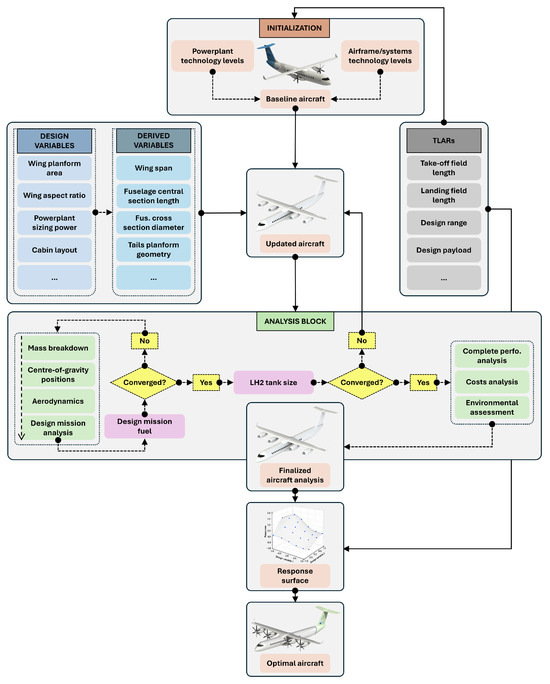
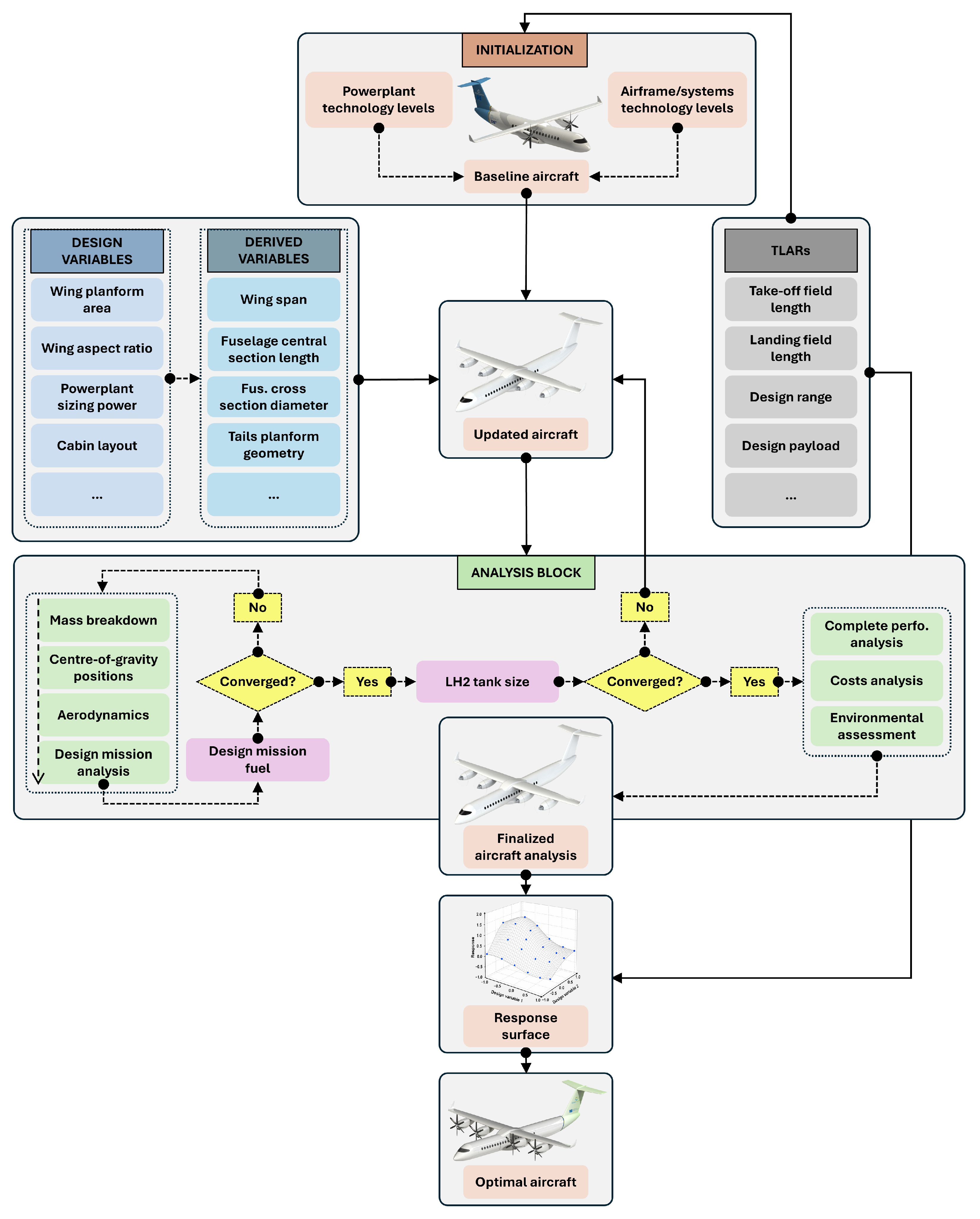
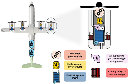
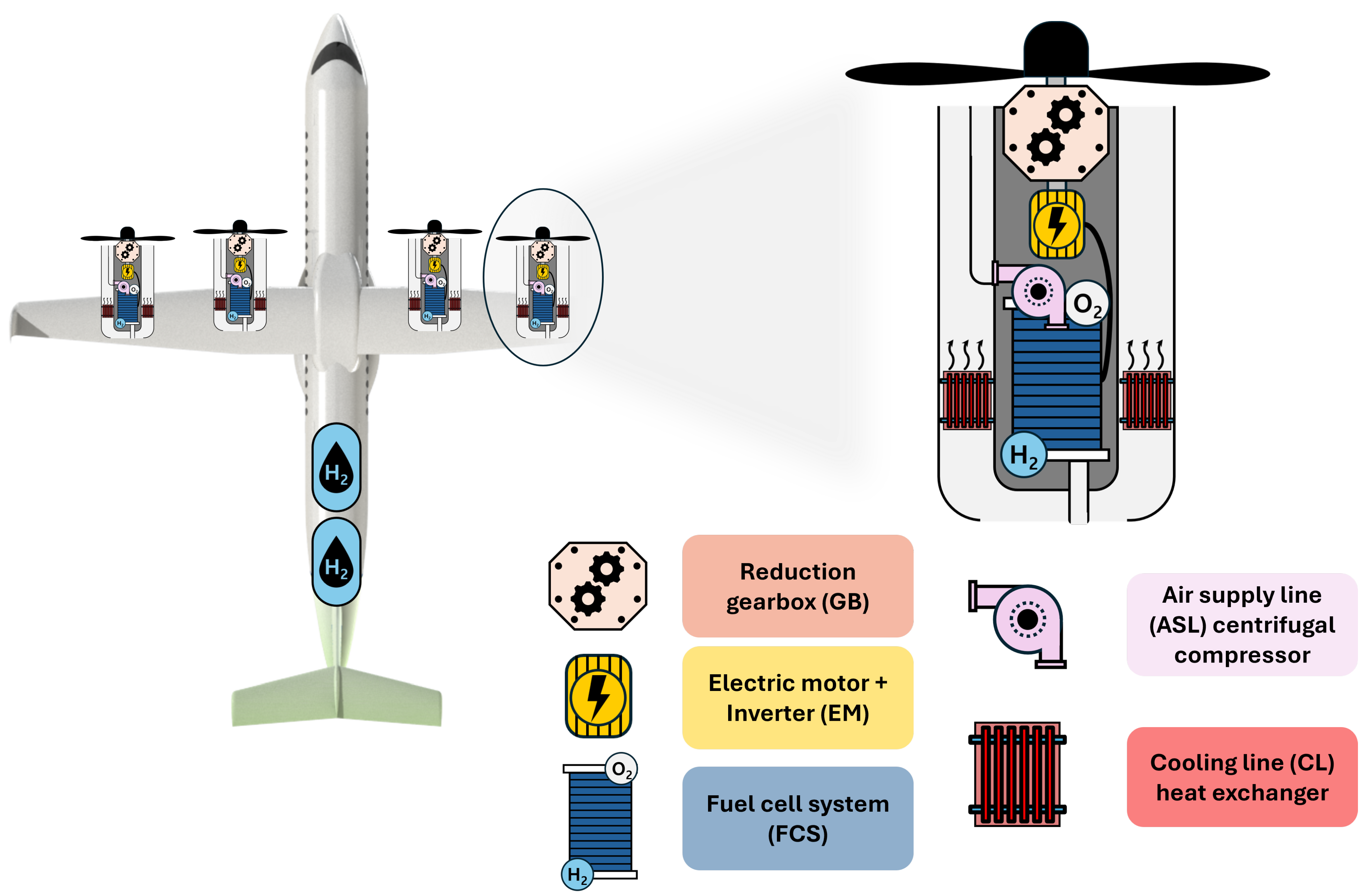
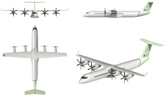
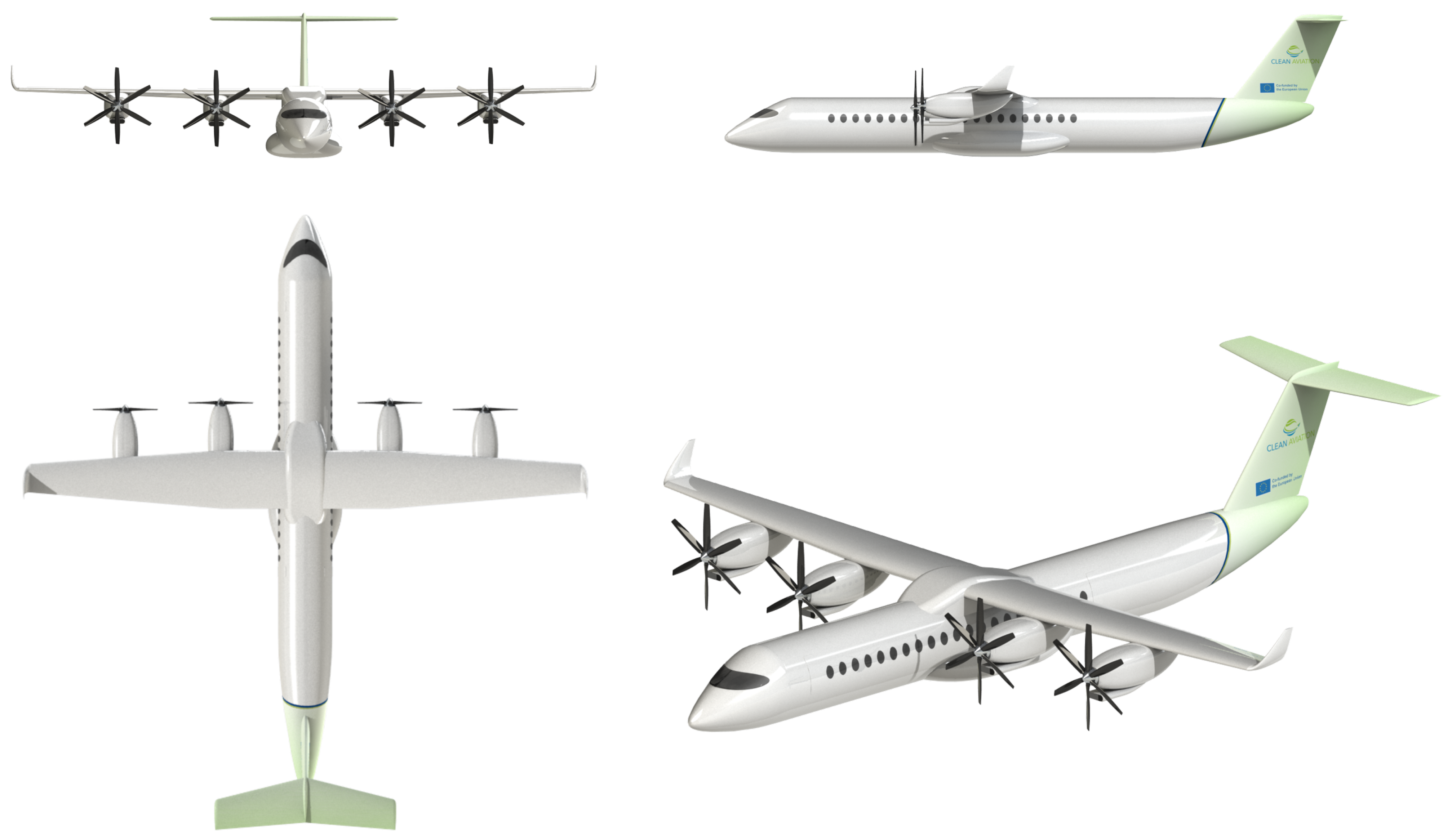
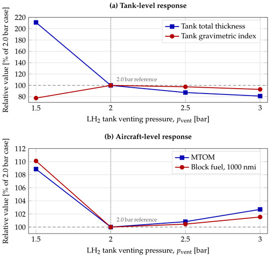
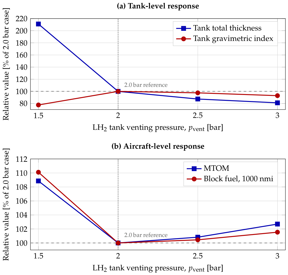
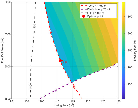
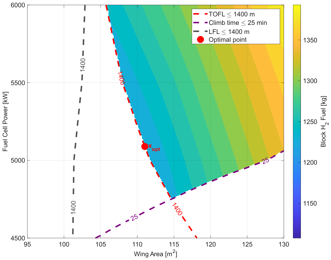
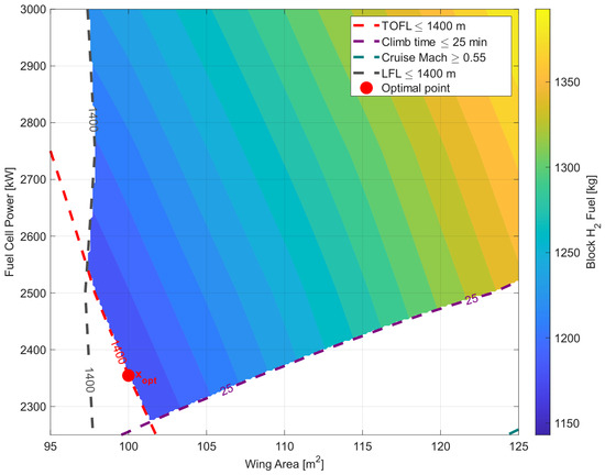
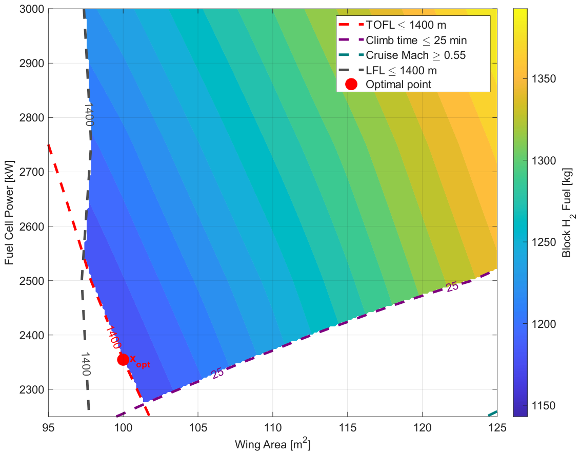
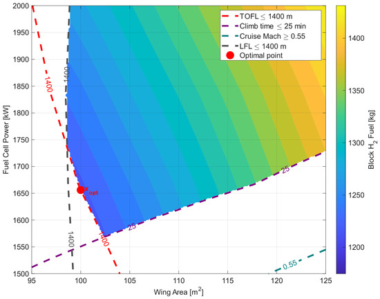
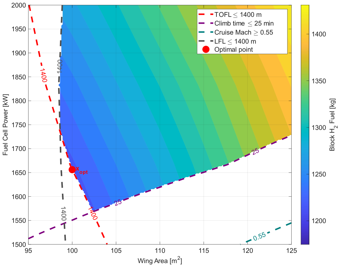
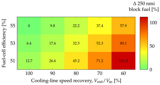
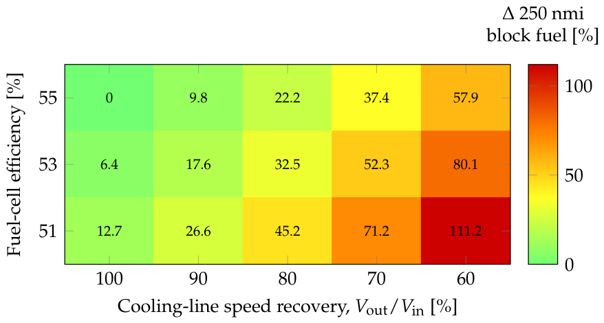
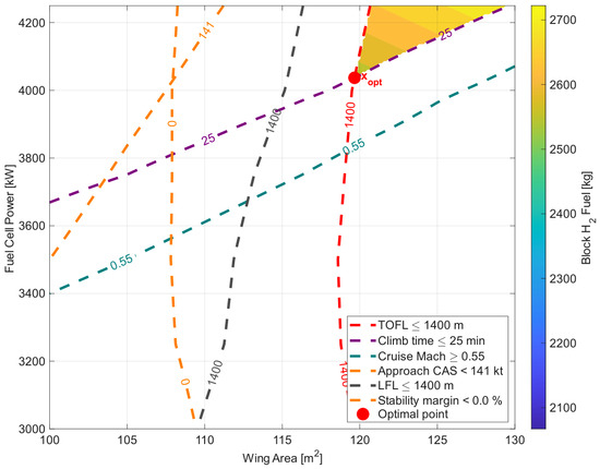
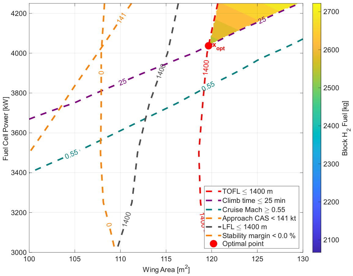
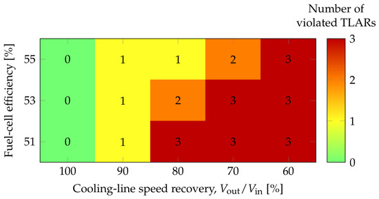
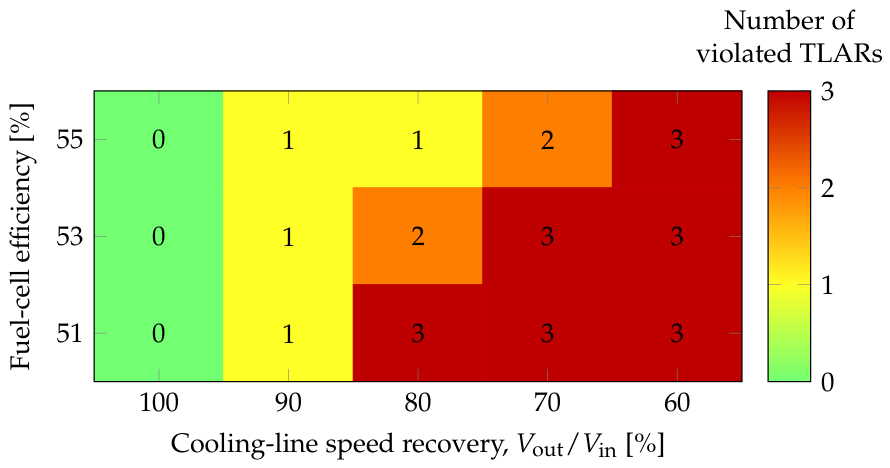

Disclaimer/Publisher’s Note: The statements, opinions and data contained in all publications are solely those of the individual author(s) and contributor(s) and not of MDPI and/or the editor(s). MDPI and/or the editor(s) disclaim responsibility for any injury to people or property resulting from any ideas, methods, instructions or products referred to in the content. |
© 2026 by the authors. Licensee MDPI, Basel, Switzerland. This article is an open access article distributed under the terms and conditions of the Creative Commons Attribution (CC BY) license.