


Abstract
Heat exchanger integration is a key design consideration for engines adapted to run on hydrogen and requiring liquid hydrogen to be preheated prior to combustion. For a typical small turboshaft, a comparison is made of fuel heating via an intercooler, a recuperator, or both in combination. This steady-state, zero-dimensional thermodynamic assessment examines the overall performance effects of the heat exchanger installations, heat loads and setpoint temperatures. It shows that exhaust gas recuperation provides up to 15% SFC reduction relative to an engine using power offtake for fuel preconditioning, with an average reduction of 14% across the evaluated operating points. Fuel heating via an intercooler is constrained by off-design and low-temperature thermal management requirements, so it only gives modest SFC benefits and will reduce specific power unless the engine is substantially redesigned. Within the evaluated design space, the combined intercooled and recuperated arrangement does not provide the lowest SFC, but it offers a balanced heat load distribution that may help to mitigate the risk of local air-side icing in the heat exchangers. Unlike previous works that considered turbofan engine architectures, this study focuses on turboshaft and turbogenerator installations where shaft power objectives and operating constraints determine the relative merits of alternative heat exchanger integration strategies. It includes an assessment of potential effects on NOx emissions as well as SFC. The study provides guidance for preliminary design and sizing of heat exchangers for fuel thermal management, but analysis of transients in the cryogenic systems and detailed assessments of aircraft-level integration penalties will be specific to particular engine applications and are beyond the scope of the present study.
1. Introduction
The ICAO Committee on Aviation Environmental Protection has projected that, by the year 2040, carbon dioxide (CO2) emissions will increase by 21%, while emissions of nitrogen oxides (NOx) will rise by 16%, compared to levels recorded in 2015 [1]. Therefore, aircraft and engine manufacturers will need to adhere to stringent regulations aimed at significantly lowering greenhouse gas (GHG) emissions. Under the Flightpath 2050 initiative, the Advisory Council for Aeronautics Research in Europe laid out ambitious objectives for the next generation of civil aircraft. Specifically, they called for a 75% decrease in CO2 emissions per passenger-kilometre and a 90% reduction in NOx emissions, taking aircraft of the year 2000 as a baseline [2].
Hydrogen propulsion has emerged as a promising solution for sustainable energy in transportation, particularly as global efforts to mitigate climate change intensify. Utilising hydrogen presents an opportunity to decarbonise various sectors, with aviation being a primary focus due to its significant carbon footprint. Hydrogen-powered systems can be broadly categorised into fuel cell technology and hydrogen combustion engines, each demonstrating distinct advantages in efficiency and emissions reduction [3,4,5]. Fuel cell systems are attractive, particularly for shorter range and regional applications, but current aviation studies and technology roadmaps continue to identify important challenges in specific power, heat rejection, air and water management, and technology maturity. Direct hydrogen combustion, therefore, remains a relevant propulsion option, especially where higher power density, operational flexibility, and compatibility with gas turbine architectures are required [6,7].
Hydrogen’s gravimetric energy density is about three times higher than that of kerosene [8], meaning it packs more energy per unit mass. This allows hydrogen to power aircraft with far less weight penalty than if using batteries, making it attractive for long-range or high-performance applications where electrification via batteries remains infeasible [9]. Despite its tremendous promise, hydrogen also presents unique challenges. Unlike conventional fuel, hydrogen is a gas at ambient conditions and cannot be stored in a traditional wing fuel tank [10]. To carry sufficient fuel for a useful range, it must be stored either as compressed gas or as liquid hydrogen (LH2) at cryogenic temperatures (∼20 K). Even in liquid form, hydrogen’s volumetric energy density is only about a quarter of that of jet fuel [11], necessitating much larger fuel tank volumes and significant aircraft design changes. Comprehensive studies on large-scale LH2 aircraft have investigated the system-level challenges of storage and integration. The Cryoplane project [12] concluded that the use of LH2 for commercial aircraft is technically feasible, while also requiring substantial further research and development, particularly because of the coupled aircraft, propulsion, storage, infrastructure, safety, and environmental challenges. More recently, the FlyZero project [13,14,15] identified green liquid hydrogen as the most promising zero-carbon fuel for scalable commercial aircraft concepts and highlighted fuel storage, thermal management, and propulsion system technologies as the key enabling challenges.
While Jet A-1 fuel system components and design considerations are well established, fuel system architectures for LH2-fuelled aircraft are still at a very low Technology Readiness Level (TRL) due to limited research and experimental data, which makes them more challenging. Radical modifications are required to Jet A-1 fuel system architectures to facilitate LH2-powered propulsion technologies [6,16]. Nonetheless, the cryogenic storage temperature of LH2 and the higher heat capacity (9.69 kJ/kg K at 20 K for LH2 compared to 1.98 kJ/kg K at 293 K for kerosene) makes it a very effective heat sink as well as a fuel [17,18]. Recent studies have also examined LH2 conditioning for retrofitted gas turbines. Ref. [19] assessed propulsion system-level LH2 conditioning for a kerosene-designed geared turbofan and showed that combustor entry delivery temperature control, bleed-source selection, fuel preheating, and engine rematching are strongly coupled. This highlights the importance of treating LH2 fuel conditioning as part of the engine cycle assessment rather than as an isolated fuel system process.
Advanced aero engine concepts have been proposed that use the cooling capacity of LH2 for intercooling or precooling the air [17,20,21,22,23,24], cooling the turbine exhaust water vapour for a condenser [25,26,27], or simply using the recuperation concept to heat up the hydrogen before injecting it into the combustor. For instance, Brewer et al. [17,20,21] introduced four new heat exchanger (HEX) configurations for a LH2-fuelled turbofan engine for a long-range passenger aircraft, namely a compressor precooler, an intercooler, a turbine cooling air heat exchanger, and an exhaust gas heat exchanger. The compressor precooler was ultimately dismissed due to significant drawbacks, including severe air-side icing risks, high pressure loss, and the necessity for extensive hardware changes, which rendered the concept heavy and impractical. While the intercooler offered some performance advantages, its disadvantages were still seen as substantial. However, later studies [28,29,30] have suggested redesigning compression systems for use with an intercooler.
The turbine cooling air heat exchanger cooled the air used for turbine blade cooling and showed promising results due to its ease of integration into existing engines without significant structural complexity. It decreased the required turbine cooling air mass flow [31], but considering the relatively small cooling air mass flow, the hydrogen temperature rise was not very significant.
Lastly, the exhaust-gas heat exchanger proved to be the most promising for heating the fuel, benefiting from a high temperature differential that allows for the design of a relatively small heat exchanger. Figure 1 shows how hydrogen might pass through multiple heat exchangers.
Figure 1.
LH2 pathway in the engine fuel system (produced based on the NASA-Lockheed concept [17]).
Ref. [30] describes a fuel system that heats hydrogen by passing it through four heat exchangers in series at high pressure. The hydrogen is then expanded through a power-generating turbine before proceeding to the combustor. The use of recuperators to preheat the air entering the combustion chamber is described in references [32,33,34]. However, these more complex systems are out of scope for the current study, as is the use of another fluid to transfer the heat [35]. The study focuses instead on thermal management just using hydrogen in an intercooler and recuperator as the primary heat exchangers.
Recent studies exploring the intercooled-recuperated concept in hydrogen-fuelled turbofan engines have revealed significant potential for improving efficiency. In these designs, the hydrogen fuel acts as a heat sink, absorbing heat from the engine’s compressor bleed air or turbine exhaust. This process enhances the efficiency of the engine, providing a useful reduction in fuel consumption when compared to simpler baseline engine cycles [22,28,29,30]. For instance, the results from [30] (for conceptual and aerodynamic design of compact heat exchangers) indicated that using the intercooled-recuperated concept decreased specific fuel consumption (SFC) by up to 7.7%, while the intercooler-only concept resulted in a 4% reduction for a high-bypass ratio geared turbofan engine. However, Patrao et al. [30] did not investigate the effect of the proportion of core air used to preheat the fuel at the recuperator, so the additional benefits that may be achievable by optimising this ratio remain unknown.
Another study by Gomez-Vega et al. [36] incorporated a series of heat exchangers (compressor intercooler, recuperator, and turbine cooling air cooler) into a two-spool turbofan engine powered by LH2 and showed energy demand reductions of 6.7–9.8%. Their study focused primarily on steady-state cruise conditions and did not fully evaluate performance at other operating points (e.g., idle, maximum take-off (MTO) and top of climb (ToC).
More recent work has also addressed the modelling fidelity of hydrogen heat exchangers in cycle analysis. Görtz et al. [37] proposed scalable heat exchanger maps for hydrogen inter-compressor cooling and showed that geometry-informed heat exchanger representations can support gas turbine performance calculations across operating conditions. Their work also highlights that simplified effectiveness-based methods can introduce uncertainty in off-design calculations, and direct hydrogen cooling may introduce icing and safety challenges.
Recent turboprop-specific work has begun to examine the coupling between hydrogen fuel conditioning and engine performance. San Benito Pastor and Parmentier [38] investigated the effect of combustor injection temperature on a hydrogen turboprop and showed that fuel conditioning requirements can influence fuel consumption, engine sizing, injection velocity, and flame-stability-related constraints.
Most prior LH2 heat exchanger studies focus on turbofans, aircraft-level turboprop integration, or fuel-conditioning temperature requirements. The relative merits of intercooling versus recuperation in turboshaft engines, including the effects of heat load, setpoint temperature, recuperator flow split, off-design operation, and HEX freezing avoidance, have therefore remained insufficiently explored.
In contrast to the mainly turbofan-focused literature, the present study addresses the LH2-fuelled turboshaft engine, for which shaft power objectives, residual exhaust energy usage, and off-design operating constraints can alter the relative benefit of intercooling and recuperation. The paper presents a steady-state comparative assessment of intercooler, recuperator, and combined intercooled-recuperated configurations, with emphasis on the effects of heat exchanger heat load, setpoint temperature, recuperator core flow split, and representative operating points on SFC, specific power, turbine entry temperature, fuel conditioning requirements, and the correlation-based emission index of nitrogen oxides (EINOx).
The novelty of the present work lies not in new component-level modelling methods, but in identifying architecture-level thermodynamic trade-offs of LH2 fuel conditioning heat exchangers integration in turboshaft engine applications that have received much less attention than LH2 turbofan ones. This addresses a clear knowledge gap. An additional motivation for selecting LH2-fuelled turboshaft engines for this study is that they may potentially serve as auxiliary power units (APUs) integrated into larger aircraft systems. Evaluating their performance with LH2 as fuel could therefore extend hydrogen’s applicability beyond smaller aircraft, potentially offering significant benefits where they are adopted for larger auxiliary, or even primary, power systems.
It should be mentioned that, although the generic cycles for turbofan and turboshaft engines are similar, their thermodynamic responses differ due to varying requirements, such as flight speed, design range, shaft power objectives, and residual exhaust-energy utilisation. The trade-off factors can be different, and this is the rationale behind the research. Broader aircraft-level integration studies, including fuel cell/turboelectric regional aircraft concepts, provide useful system context [39], but remain outside the present scope.
2. Framework for Evaluating the LH2-Fuelled Turboshaft Engine Performance
The objective of this study is to investigate the feasibility and performance potential of LH2 as a fuel for regional aircraft engines. To achieve this, a progressive modelling framework was developed, in which a validated baseline engine was systematically adapted to incorporate hydrogen fuelling and advanced thermal management concepts. The framework proceeds through the following stages:
- (1)
- Selecting a baseline engine, which is the Pratt & Whitney PW127 engine [40,41] as used in the ATR 72 [42,43,44] regional aircraft.
- (2)
- Performing design and off-design cycle studies for the baseline engine with Jet A-1 fuel.
- (3)
- Changing the fuel type to hydrogen and conducting design and off-design point studies (like those on the baseline engine) for comparative analysis. In this step, the modified engine cycle is without heat exchangers.
- (4)
- Adding heat exchangers (intercooler (IC), recuperator (RC), and intercooler with recuperator) to the modified engine configuration.
- (5)
- Exploring the effect of heat exchangers on the modified engine performance at its design point by performing a parametric study on the heat loads for the different heat exchangers.
- (6)
- Examining the impact of proposed intercooled-recuperated architectures on the modified engine performance and conducting a feasibility study on them.
2.1. Modelling Setup and Baseline Engine Calibration
2.1.1. Baseline Engine Selection and Data: PW127 with Jet A-1
The selected baseline engine is the Pratt & Whitney PW127, which is a twin-spool engine [40,41] with a free power turbine. The engine cycle is modelled as a turboshaft (without its propeller and reduction gearbox) in Siemens Amesim [45] using the Gas Turbine Performance library (Figure 2). The library provides component models (compressor, turbine, combustor, etc.) that can be integrated into a full engine architecture, as demonstrated with real engine data such as the GE T700 turboshaft engine in reference [46]. For instance, in the stepwise fuel flow changes from 100% to 105% and from 105% to 95% scenario, the model predicted the gas generator shaft speed within 0.05% of the experimental measurements. (This benchmark is not used for direct validation of the PW127 model developed here, but is cited to demonstrate the capability of the modelling environment, and justify its use in the thermodynamic cycle analysis.)
Key input parameters, including compressor pressure ratios, combustor outlet temperature (COT), component efficiencies, and air mass flow rate, were selected to match reported specifications from the literature [40,41,47,48], including the fuel flow rate, overall pressure ratio (OPR) and output power. Table 1 represents the design-point (MTO) calibration of the baseline Jet A-1 model.
Figure 2.
PW 127 engine [49] and its model in Siemens Amesim.
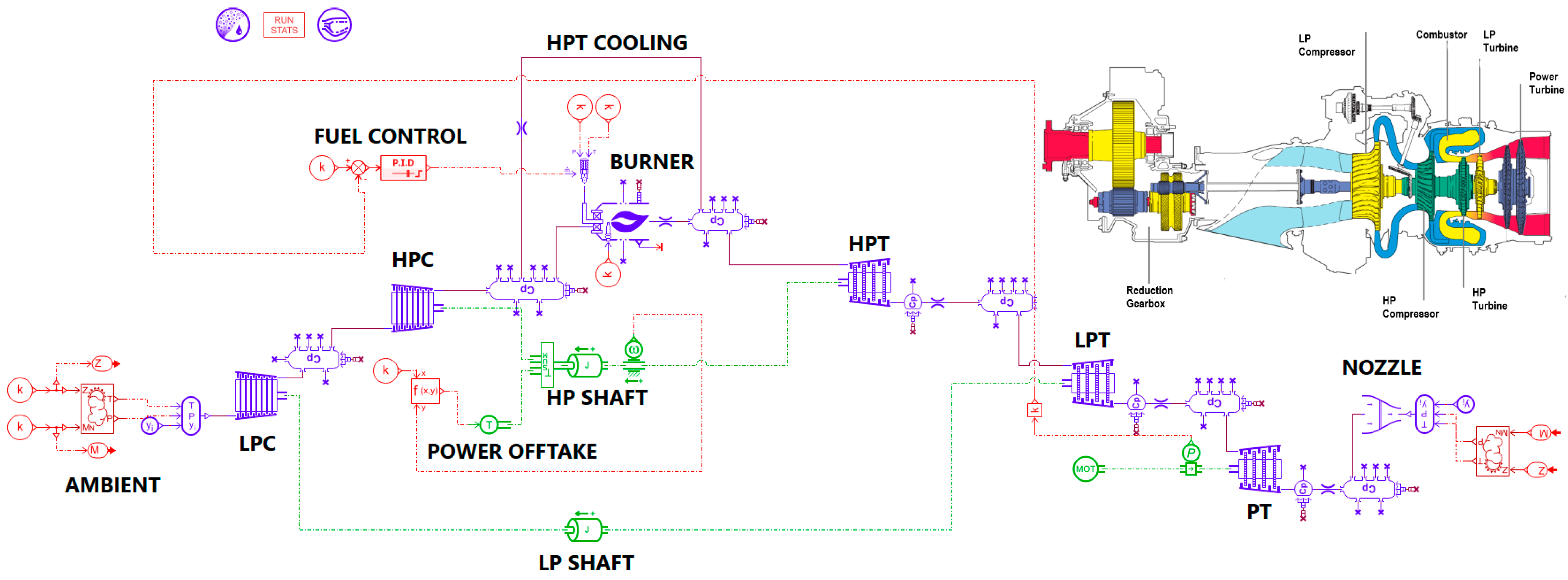
Table 1.
Baseline engine performance specifications at MTO (design point) for Jet A-1.
It is important to recognise that detailed turbomachinery efficiency maps and some cycle parameters, such as pressure drops and power offtakes, are not publicly available. Therefore, those parameters were estimated based on studies of technology trends and similar engine types found in gas turbine engine design references [50,52,53]. Consequently, the model should be regarded as a design-point-matched PW127-class baseline suitable for comparative cycle analysis, and not as a proprietary PW127 engine model independently validated over the full off-design envelope.
Similarly, the LH2-fuelled configurations are not independently validated against experimental hydrogen turboshaft data, since such data are not publicly available. The hydrogen cases, therefore, present comparative steady-state trends obtained by applying consistent modelling assumptions to the matched baseline engine. Accordingly, the conclusions are restricted to predicting relative trends between heat exchanger configurations at the architecture level rather than providing precise predictions for a certified PW127 engine converted to hydrogen operation.
2.1.2. Engine Cycle Model and Global Assumptions
The engine is represented as a zero-dimensional steady thermodynamic cycle with real gas properties. The model comprises: low-pressure and high-pressure compressors (LPCs/HPCs), high-pressure and low-pressure turbines (HPTs/LPTs), a single power turbine (PT), a single annular combustor, mechanical shafts (HP/LP/PT), ducts, and bleed air for HPT cooling. Component map scaling factors are applied consistently to all off-design cases. The combustor in the analysis is modelled with predefined efficiency and associated pressure loss, allowing for a realistic assessment of its performance. Turbomachinery component efficiencies and heat exchanger pressure losses account for all other duct losses. Off-design performance is evaluated at idle, cruise, and ToC, in addition to the design point (MTO). Each point is defined by ambient conditions and a constant PT rotational speed, so the engine power is modulated solely by fuel flow. At each off-design operating point, performance is posed as a set of nonlinear algebraic balances with unknowns chosen to match the components (e.g., corrected shaft speeds, corrected mass flow rates). The solver iterates these unknowns until (a) mass flow continuity holds across every component, (b) shaft power balances are satisfied on both HP and LP spools, and (c) energy balances close across all components. Convergence is achieved when the residuals in mass and power balances drop below the specified tolerances. Compressor and turbine maps provide the off-design characteristics utilised during the iterative process. This formulation adheres to standard practices for matching compressors and turbines, employing nonlinear root-finding methods, such as Newton-type methods, which are commonly used for off-design simulations of gas turbines. In modelling the heat exchanger variant cycles, synthesis mode was utilised rather than design point mode to show what would be achieved if the heat exchanger engine variants were constrained to using the same existing hardware.
After running the engine simulation at off-design conditions (idle, cruise, and ToC), the key performance data are presented in Table 2.
Table 2.
Baseline engine off-design points performance (Jet A-1).
To make fairer comparisons regarding the fuel consumption changes with respect to changing the fuel type from Jet A-1 to hydrogen, the energy-based specific fuel consumption (ESFC) parameter is used [54]. By incorporating the energy content of the fuel, the ESFC avoids the need to consider the impact of the LHV for various fuels and enables the actual energy efficiency of engines with different fuel types to be compared. The ESFC can be expressed as below (Equation (1)):
For the turboshaft engine application, the ESFC is a non-dimensional number where smaller is better.
2.2. Fuel Properties and Thermodynamic Modelling
2.2.1. The Effect of Hydrogen Fuel Temperature and Its Range Limits
The effect of changing the hydrogen fuel temperature in the burner can be seen in the change in its enthalpy, as indicated in Equation (2) [55]:
where is the specific heat and is the enthalpy of formation with respect to the reference temperature (, which is 298.15 K. The can be expressed as below (Equation (3)):
where is the universal gas constant (8.3145 J/mol·K). The coefficients of to can be obtained from the NASA report [56].
For the performance study, the hydrogen injection temperature range at entry to the combustion chamber needs to be defined. For the minimum temperature limit, air-side freezing must not occur, and the combustion process must be stable, so according to [6,57,58], the minimum temperature is 150 K and ideally above 273 K. For the maximum limit, the hydrogen auto-ignition temperature might be used, which is around 673 K at atmospheric pressure [59]. However, three other factors should also be considered: (1) providing cooling capacity for the injectors and maintaining the combustor’s structural integrity, (2) engine performance gain by injecting fuel at higher temperatures, and (3) NOx emissions [60]. These three factors are not aligned in the same way, so a compromise is needed based on the design choices. Therefore, 500 K is selected as the maximum allowable hydrogen injection temperature for this study, and 200 K is selected for the minimum hydrogen injection temperature, considering the temperature validity domain for the coefficients based on the NASA report [56].
For hydrogen circulating through the heat exchangers and HP pump, the fuel is assumed to be in the fully parahydrogen state, since at around 25 K the equilibrium composition is about 99.8% parahydrogen [61]. This assumption is also made during the simulation and heat transfer process, as conversion from para to ortho is not instant and can take hours [30,61,62]. Furthermore, the Helmholtz energy equation of state (EoS) is used for the simulation, as it offers the most accurate prediction of the hydrogen thermodynamic properties and a broader validity domain (up to 1000 K and 20 kbar) [61,63]. For compactness, the full equations are omitted; details are available in [61].
The hydrogen initial condition after the HP pump is taken to be 20.5 bar and 25 K at MTO for the engine performance studies. This pressure is 30% higher than the air pressure at the exit of HPC to account for the likely pressure drops across the fuel flow regulator and the combustor fuel injectors [64]. Note that the fuel pressure should be substantially higher than the air pressure in the combustion chamber for good fuel-air mixing and stable combustion [65].
2.2.2. Correlation-Based EINOx Estimation
The EINOx was estimated using a lower-order correlation developed for a hydrogen micromix combustor within the ENABLEH2 project [66] and subsequently applied to hydrogen aero engine cycle studies. This correlation was chosen because the current analysis is a steady-state cycle-level assessment, which does not delve into combustor geometry, injector-level mixing, flame residence time, or detailed chemical kinetics. Therefore, the EINOx calculation aims to provide a comparative indication of the relative EINOx tendencies across different heat exchanger configurations, rather than delivering an absolute emissions prediction specific to a particular combustor design. The following equations (Equations (4) and (5)) are used for estimating the EINOx:
where , , , , , and are HPC exit pressure in kPa, HPC exit temperature in K, hydrogen injection temperature in K, fuel-air mixture temperature in K, specific heat capacity in J/kg·K, and the fuel-air equivalence ratio, respectively. These parameters were computed after each simulation to eventually calculate the EINOx as the output. It should be noted that, to account for the variable hydrogen injection temperature, depending on the heat exchanger configuration and operating point, the effect of fuel temperature was included in the EINOx calculation through the corrected mixture temperature (Equation (5)). This approach was proposed by Reference [30].
The ENABLEH2 micromix combustor report [66] shows that hydrogen NOx formation is strongly affected by combustor inlet pressure, inlet temperature, equivalence ratio, injector design, fuel-air mixing, flame interaction, and residence time. The lower-order correlation, therefore, captures only the first-order influence of cycle-level variables. It does not distinguish between different hydrogen combustor concepts, such as micromix, lean direct injection, staged combustion, or other flashback-control strategies [67]. It also does not account for local equivalence ratio distributions, detailed injector geometry, fuel staging, wall heat losses, thermoacoustic behaviour, or combustor pattern factor. Furthermore, to assess the sensitivity of the correlation to the equivalence ratio, an additional local sensitivity analysis was performed by perturbing the cycle-calculated while keeping , , , and specific heat capacities constant. So, a ±10% perturbation in changes the estimated EINOx by approximately −19%/+20%, while a ±20% perturbation changes it by about −35%/+43%. It should be noted that a physically consistent variation in would require changing fuel flow and rematching the engine, because fuel flow affects shaft power, TIT, combustor conditions, and air mass flow. Such a rematching study is outside the scope of the present work. Consequently, the variation in equivalence ratio is used only to demonstrate the sensitivity of the NOx estimation and to support interpreting the reported EINOx values as relative correlation-based trends.
Although direct hydrogen combustion eliminates fuel carbon and CO2 emissions, it does not eliminate all climate-relevant emissions. Hydrogen combustion still produces water vapour and NOx, and these species may contribute to non-CO2 climate effects depending on altitude, atmospheric conditions, combustor technology, and aircraft operation. In particular, increased water vapour emission can influence contrail formation, while NOx emissions affect atmospheric chemistry. Therefore, the present EINOx results should be interpreted only as cycle-level, correlation-based emissions trends. The study does not try to quantify contrail formation, effective radiative forcing, or total climate impact.
2.2.3. Effect of Fuel Preconditioning (Heating and Pumping)
Initially, it was assumed that for the modified hydrogen engine, hydrogen was being injected into the combustion chamber in a conditioned way at 300 K, and the comparison with respect to the Jet A-1 fuelled engine was primarily reflecting the change in fuel LHV. However, in order to compare the hydrogen-powered engine with different heat exchanger configurations, it is necessary to take into account the amount of power needed, from the high-pressure fuel system point of view, to pressurise liquid hydrogen via the HP pump and to vaporise it from liquid to the supercritical phase at 300 K. The hydrogen initial condition at entry to the HP pump (i.e., after the cryogenic tank and the booster pumps) is assumed to be liquid at 4 bar and 24 K.
For the HP pump’s required power, a performance map was selected from [17]. The pressure rise and the volumetric flow rate of the original map were scaled to match the design point specifications (efficiency of 77%, pressure rise of 16.5 bar and volumetric flow rate of 54.32 L/min with a reference density of 70 kg/m3). The map data was implemented in Amesim using two look-up tables: one for pressure rise and another for efficiency calculations based on volumetric flow rate and rotational speed. The pumping power was calculated as below (Equation (6)):
where , , , and are the pump efficiency, fluid density, pressure, and mass flow rate, respectively. Furthermore, for the heating, a simple electric heater model was used (Equation (7)) to calculate the required power based on the fuel mass flow rate, the inlet and outlet temperatures, and the specific heat capacity. Since temperature change is significant, the specific heat was computed by taking the enthalpy change average, as shown in Equation (8).
The hydrogen properties (e.g., density, enthalpy, etc.) at each state were computed and available using the in-built Amesim fluid properties and Helmholtz EoS mentioned in Section 2.2.1.
The total power for preconditioning was extracted from the HPT as a form of power offtake that can be seen as a result of the extra torque required, as below (Equations (9) and (10)):
where , , , and , are the power offtake in kW, high-pressure shaft rotational speed in rpm, HP compressor torque, and HP turbine torque in N⋅m, respectively. It is important to note that the power offtake is utilised for various components, such as fuel pumps, oil pumps, accessory gearboxes, and generators [68,69]. To accurately account for these effects, the baseline power offtake of the Jet A-1 fuel engine was added (Equation (8)). Analysis indicates that the power required for the Jet A-1 fuel pump is very low, at approximately 0.5 kW for a fuel flow of 166.4 g/s [70], so its effect on performance is negligible.
2.2.4. Heat Exchanger Modelling and Configurations
In this section, different heat exchanger configurations and modelling procedures are described. The baseline hydrogen engine architecture and the heat exchanger architectures integrated within the hydrogen engine in this study are illustrated in Figure 3.
Figure 3.
Hydrogen engine architectures with HEX ((a) baseline, (b) IC only, (c) RC only, and (d) IC with RC).
The three main heat exchanger architectures are as follows:
- Intercooler only: This configuration uses only the intercooler that is placed between the LPC and HPC to cut compressor work (by reducing HPC inlet temperature) and improve surge margin, while picking up heat for the hydrogen fuel.
- Recuperator only: This configuration uses a recuperator after the PT to exchange some heat from the turbine exhaust to the LH2 coming from the HP pump. In this concept, there are three key questions that need to be answered (Figure 4):Figure 4. Three different flow arrangements for the recuperator-only concept ((a) two-nozzle concept, (b) single-nozzle concept, and (c) an extra HEX concept).
- a.
- What percentage of the core flow goes through the recuperator to achieve the best SFC reduction? (Figure 4a)
- b.
- The remaining core flow can either be mixed with the flow at the exit of the recuperator, or the two flows may be released through separate nozzles. Which architecture will provide the better performance? (Figure 4b)
- c.
- What is the performance potential that can be achieved with the exhaust flow after the recuperator? Might it be beneficial to also use another heat exchanger to heat up the HPC exit air flow before it goes to the combustor? (Figure 4c)
- Intercooler with recuperator: In this configuration, the intercooler and the recuperator exchange heat from the air and exhaust gas side to the hydrogen to heat it up before it is injected into the combustor. This concept is selected to be integrated with the baseline hydrogen engine, and the optimisation of the heat load management between the intercooler and the recuperator is carried out based on this architecture.
The heat exchanger modelling is based on the effectiveness-NTU (e-NTU) relationship, where NTU stands for the number of transfer units. This method was selected, as unlike the log-mean temperature difference (LMTD) method, it does not require a cumbersome iterative process when only the inlet temperatures are known [71,72]. Therefore, the evaluation of the overall engine performance in this study is performed without needing to model detailed heat exchanger geometry. The equations (Equations (11)–(14)) used are as follows [73]:
where , , and are the actual heat flow rate, the maximum possible heat flow rate, and the effectiveness, respectively. It needs to be mentioned that, as using the full capacity of the e-NTU method needs specific geometry and configuration definition (that is out of scope for this research), in this study, the effectiveness is an input, which can be implemented by the control system.
Furthermore, in the air-side half of the heat exchanger model, pressure loss was represented using an equivalent thermal-pneumatic orifice with a constant flow coefficient . A nominal value of was adopted as a surrogate restriction parameter, and also to match the reference heat exchanger model in [30]. This value lies within the broad range commonly reported for orifice-type flow coefficients (approximately 0.6–0.9 [74]), although it should not be interpreted as a geometry-specific heat exchanger air-side parameter. Equations (15) and (16) are used to calculate the air-side (compressible flow) pressure drop:
where , , , , , , and are the flow parameter, the specific heat ratio, the gas constant, the upstream temperature, the downstream pressure, the upstream pressure, and the flow passage area, respectively.
In the hydrogen-side half of the heat exchanger model, the pressure drop was calculated based on the Darcy-Weisbach [75] equation (Equation (17)):
where are pressure drop, friction factor, and heat exchanger length, respectively. It needs to be mentioned that instead of relying on the Moody Chart [76] for the friction factor calculation, which requires iterative processes, Churchill [77] proposed using the empirical equation to determine the friction factor, which is highly dependent on the Reynolds number (Equations (18) and (19)):
In the Reynolds number equation (Equation (18)), , are density, velocity, diameter, and viscosity, respectively, and in Equation (19), is surface roughness. In this study, the hydrogen-side passages were assumed hydraulically smooth, so surface roughness was neglected in the friction factor calculation. This assumption may underpredict fuel-side pressure loss, but its effect is expected to be smaller than the uncertainty associated with the air-side pressure loss model. For the two-phase flow and considering homogenous flow behaviour, meaning that two phases have the same velocity (no-slip) and temperature (equilibrium) [78], McAdams et al. [79] was used (Equation (20)):
where and are the mixture viscosity and the gaseous mass fraction, respectively.
As the focus of this study is the exploration of alternative fuel systems and heat exchanger architectures, a baseline heat exchanger is selected from [30], with specifications as listed in Table 3. Furthermore, a replication of the heat exchanger model was made to compare the simulation results (in Amesim) with those reported by Patrao et al. [30]. The results are presented in Table 4.
Table 3.
Baseline heat exchanger geometry specifications and boundary conditions.
Table 4.
HEX performance comparison.
As the results from the simulation match well with the literature, the Amesim simulation is used for the architecture exploration study.
2.2.5. Control Strategy
In this study, a two-layer control scheme was used to separate power regulation from fuel thermal conditioning. In the outer power loop, a target engine output power was specified. Actual power was computed from the measured PT torque and rotational speed, and the resulting error drove a hydrogen fuel flow controller. That controller metered combustor fuel so that the delivered shaft work matched the demand. It was implemented as a PI regulator with anti-windup and rate limiting, which kept the response stable and consistent across operating points. In parallel, a thermal supervisory loop imposed a desired hydrogen injection temperature at the combustor inlet. For the heat exchanger control, effectiveness was adjusted to track the target temperature. To do so, the controller used air-side mass flow and the inlet/outlet temperatures on both the air and fuel sides, together with the instantaneous hydrogen mass flow, to determine the required change in heat exchanger effectiveness. Admissible effectiveness was restricted to respect temperature limits. These loops enabled power to remain at its setpoint while the fuel was delivered to the combustor within the specified temperature range, allowing for fair comparisons across different heat exchanger configurations. In the control strategy, PT torque and PT speed were fed back to the fuel flow controller to close the power loop, while air-side and fuel-side temperatures and flows were fed to the heat exchanger temperature controller to close the thermal loop. The gas turbine core acted as the plant for both loops: commanded fuel flow set combustor heat release and turbine work (closing the power loop), whereas the scheduled heat exchanger effectiveness conditioned the fuel to the prescribed injection temperature (closing the thermal loop). With this arrangement, shaft power was held at its setpoint while the fuel temperature was maintained within the required window.
3. Results and Discussions
In this section, the results of engine cycle modification with different heat exchanger configurations are presented. The engines are all scaled to meet the same design-point shaft power requirements.
3.1. The Modified Engine (Uncooled) Performance with Hydrogen
The fuel for the baseline engine is changed from Jet A-1 to hydrogen, which has an LHV of 120.2 MJ/kg. This altered engine is referred to as the modified engine. In this configuration, the air mass flow rate, OPR, and output shaft power, as well as the efficiencies of the components, are maintained, as this setup provides the necessary conditions for a comparative study. The full cycle performance data for the target engine with hydrogen are provided in Table 5 (the same methodology as described in Section 2.1.1 was applied). The ESFC comparison between Jet A-1 and hydrogen for the modified turboshaft engine is presented in Table 6.
Table 5.
Modified engine full cycle performance (Hydrogen).
Table 6.
ESFC comparison (Jet A-1 and Hydrogen).
As indicated above, ESFC for the modified hydrogen-powered engine is, on average, about 2% lower than the Jet A-1 baseline turboshaft engine. When ESFC is lower, it means that the engine is more efficient (a smaller and more compact engine), and for hydrogen, the outcome is matched by previous studies [36,54,80]. However, in those results, the fuel was assumed to be preconditioned. In Section 3.2, the energy required for hydrogen preconditioning is investigated to evaluate more realistic changes in performance.
3.2. The Baseline Hydrogen Engine Performance (with Fuel Preconditioning)
To account for the power offtake for fuel preconditioning, the expected performance from the HP pump and an electric heater for fuel vaporisation are presented in Table 7.
Table 7.
HP fuel pump performance and electric heater power requirement (pump exit temperature is 25 K).
It is assumed the baseline hydrogen engine uses electric heating to vaporise LH2 for combustion. Its turbomachinery architecture and components are the same as that of the PW 127 type engine described in Section 2.1.1. Based on the information in Table 7, for the 300 K hydrogen injection temperature in the baseline hydrogen engine and pressurising the liquid hydrogen at MTO, 264.8 kW of power is needed. Now, this amount of power offtake for the hydrogen conditioning is added to the modified hydrogen engine model, which is hereafter called the hydrogen baseline engine. The effect of heat exchanger configurations will be compared with respect to the hydrogen baseline engine. The cycle performance data for the baseline hydrogen engine that maintains the same net shaft power output, OPR, air mass flow rate, and component efficiencies at the MTO design point are presented in Table 8. This specific basis for comparison has been chosen in preference to various potential alternatives, and according to Table 7 and Table 8, the ESFC comparison is presented in Table 9.
Table 8.
Hydrogen baseline engine full cycle performance (with fuel conditioning 300 K).
Table 9.
ESFC comparison (Jet A-1 baseline versus H2 baseline).
When considering the impact of hydrogen fuel conditioning, it is evident that the ESFC increased compared to the baseline Jet A-1 engine (6.8% on average). This increase is expected, as a significant amount of power is required for hydrogen preconditioning. However, the data from the baseline hydrogen engine will serve as a useful reference for comparing different heat exchanger configurations.
3.3. Engine Performance with Alternative Heat Exchanger Configurations
For the liquid hydrogen fuelled engine, its efficiency can be improved by using heat exchangers to preheat the hydrogen instead of using power offtake for an electric heater. Six alternative engine configurations are investigated. The hydrogen might be preheated in an intercooler between the LP and HP compressors, or by turbine exhaust heat in a recuperator. The recuperator might just use a proportion of the PT exit flow bled off from the jet pipe.
Table 10 compares the performance of the different engine configurations at MTO. For this table, the exhaust nozzle area is held constant, and the heat exchangers would all preheat the hydrogen to 300 K. However, there is potential to preheat the hydrogen to higher temperatures to achieve greater SFC benefits, as discussed below. It is important to note that the GH2 baseline engine uses conditioned hydrogen (300 K), which is injected into the combustion chamber without requiring any power for preconditioning the hydrogen. It can be observed that its SFC is lower than the LH2 baseline (as presented in Table 9), as well as lower than the configuration that uses only an intercooler. This is expected, as the GH2 baseline engine represents an ideal configuration, whereas a realistic configuration must consider the effects of fuel conditioning.
Table 10.
Comparison of possible heat exchanger cycles with the LH2 baseline cycle at MTO (ISA+19.4 K).
In Table 10, the calculated pressure drops indicate that the intercooler imposes the primary hydraulic penalty on the air side, while the losses on the hydrogen side remain relatively minor, as supported by the references [28,30] and the simulation results in Table 4, where the air-side pressure drop was 1.80%, while the pressure drop for the hydrogen side was 0.09%. In the cases involving the recuperator, the current cycle model predicted low pressure-drop penalties, especially for the hot side. Since both the recuperator and intercooler were modelled using the same simplified heat exchanger geometry, and given that the recuperator functions within the exhaust-side matching of the turboshaft free PT system, these predictions should be viewed as architecture-level estimates rather than precise component forecasts. Nonetheless, the overall trend emphasises that air-side pressure loss is a significant factor in intercooling, whereas the performance of the recuperator in this study is heavily influenced by the assumed low-loss integration.
3.3.1. Intercooler-Only Configuration
In the intercooler-only concept, an increase in fuel injection temperature leads to a decrease in SFC, specific power, and TIT (Figure 5). Additionally, the OPR increases by 1% to 3%, depending on the operating conditions and the fuel temperature. While having lower SFC and TIT is beneficial, lower specific power implies higher required airflow for the same power (a potential sizing penalty). Since the engine geometry, output shaft power and the power turbine rotational speed are held constant, a reduction in specific power directly implies that the matched operating point requires a higher total air mass flow rate. This behaviour is consistent with an intercooled cycle in which the heat exchanger both lowers the compressor delivery temperature and introduces an additional pressure loss. These effects shift the compressor-turbine matching to a different operating condition of the gas turbine engine. In this rematched condition, it is possible to observe a slight increase in OPR while the required fuel-to-air ratio decreases, which reduces TIT and, for the fixed power constraint, improves SFC.
Figure 5.
SFC, Sp Power, TIT, and OPR changes in the intercooler-only concept vs. the H2 baseline engine.
For each operating condition, the maximum allowable fuel temperature after the intercooler is constrained by the physical limitations of the heat exchanger, such that the outlet temperature of the cold flow cannot exceed the inlet temperature of the hot fluid. The upper temperature limits are 470 K for MTO, 405 K for ToC, 397 K for cruise, and 385 K for idle. Furthermore, as previously mentioned, the lower limit for the fuel injection temperature into the combustion chamber, as required for stable combustion, is set at 200 K.
In the intercooler-only concept, apart from potential local icing, a problem with using hydrogen alone as the coolant in the intercooler is that it does not give a lot of cooling in return for the extra air-side pressure loss. In a recent study by Miltén et al. [81] (for a turbofan engine concept), adding a bypass duct air intercooler stage can provide meaningful temperature reduction with no hydrogen safety exposure, but it demands a large coolant flow ratio and bulky heat exchanger hardware, adding drag and pressure loss penalties.
From a performance perspective, intercooling generally benefits SFC only when it is used to allow for increased OPR, which is rarely an attractive option in small engines. In this case, however, the heat extracted from the core is returned directly to the fuel, avoiding the need for power offtake to an electric heater.
3.3.2. Recuperator-Only Configuration
For the recuperator-only concept, an initial selection of 25% of the core mass flow after the PT is made to pass through the recuperator. A sensitivity analysis is then conducted to vary the mass flow rate fraction to the recuperator from 10% to 50% at MTO (design point). It is important to note that the upper and lower limits of the mass flow fraction are determined by physical constraints: the lower limit represents the minimum mass flow rate required to meet the fuel temperature requirements, while the upper limit indicates the maximum fraction that can be directed into the recuperator while satisfying the PT back-pressure requirement for engine operation. The results for different recuperator mass flow rates are illustrated in Figure 6 and Figure 7.
Figure 6.
SFC, Sp Power, TIT, and OPR changes in a recuperator-only concept vs. H2 baseline engine (25% of the core mass flow rate with two separate exhaust nozzles).
Figure 7.
SFC, Sp Power, thrust, and HEX power changes with recuperator vs. baseline H2 engine (10% to 50% of core mass flow rate with two separate exhaust nozzles at MTO).
In both cases, the exhaust nozzle geometries remain the same in comparison to the baseline H2 engine. By increasing the air mass flow rate through the recuperator, the SFC and the residual thrust are reduced while the specific power is increased, regardless of the fuel injection temperature. Additionally, there is a slight reduction in the recuperator’s heat flow rate due to the increased air mass flow rate fraction. This reflects the increase in specific power, which would enable the whole engine to be scaled down, including the heat flow rate. As for the specific power, its trend increases with a higher mass flow rate fraction. However, only at values above 40% does the absolute specific power exceed that of the baseline engine. Furthermore, increasing the core mass flow ratio for the recuperator indicates that the engine becomes more suitable for turbo generator applications, as it results in reduced residual thrust. In contrast, higher residual thrust is more advantageous for turboprop applications. Finally, the results are presented only at the MTO condition for the sake of simulation efficiency and time, as the previous analyses show that the overall trend remains consistent across different operating points.
- ▶
- Recuperator concept with a single exhaust nozzle and target fuel temperature of 300 K at MTO
In this concept, both the core flow after the PT and the air going through the recuperator will be mixed and exit from a single exhaust nozzle. A sensitivity analysis is made to evaluate the effect of nozzle exit radius, which also means the exit area, on the different performance parameters (Figure 8). It is observed that by mixing the core flow and the recuperator exit flows, and using a single nozzle identical to that of the baseline LH2 engine, the overall performance of the engine (in terms of SFC, specific power, TIT, and OPR) is not as good as the two-nozzle design. To enhance the engine performance, it is recommended to increase the nozzle exit radius by more than 10%. Additionally, it was noted that altering the mass flow rate directed to the recuperator in the single-nozzle design (ranging from 10% to 100%) did not impact engine performance, as the air mass flow rate, OPR, and TIT remained constant.
Figure 8.
Engine performance changes in the single-nozzle concept vs. the two-nozzle concept (with recuperator).
- ▶
- Recuperator concept with an additional turbine-exhaust heat exchanger to raise the combustor inlet air temperature
In this concept, the main goal is to determine the possible performance gain if an additional heat exchanger after the PT is used to heat the HPC exit air before going to the combustion chamber. This recuperated arrangement is common in small ground-based gas turbines. Based on the engine cycle results with intercooler-only and recuperator-only concepts, the HPC air exit temperatures for the target fuel temperature of 300 K are 730 K and 753 K, respectively. Furthermore, the hydrogen recuperator exhaust gas exit temperatures with 10% to 50% core mass flow rate ratio are 553 K and 728 K, respectively.
As a result, since the target for the extra heat exchanger is to raise the HPC exit air temperature, placing the heat exchanger right after the hydrogen recuperator is not logical, as there will be no performance benefit (because of the reduced gas inlet temperature). It is better to place the heat exchanger in the main core flow from the PT, after a portion of the flow has already been extracted for the hydrogen recuperator, and where the gas temperature (at the entry to the extra heat exchanger) is around 770–810 K, depending on the recuperator mass flow rate ratio (the lower the mass flow rate, the higher the main gas temperature). Based on the analysis in the previous section, using the single-nozzle concept without changing the nozzle geometry adds a penalty in SFC and in specific power (Figure 9), so the only concept investigated is the two-nozzle architecture (one for the main flow and one for the recuperator).
Figure 9.
Engine performance changes by adding an extra HEX in the recuperator concept.
Based on the figure above, it can be concluded that while combining a recuperator with an additional heat exchanger reduces SFC by an average of around 17% for both the 25% and 50% recuperator mass flow cases, the addition of the extra heat exchanger to the recuperator-only concept only results in an average SFC reduction of about 3%. Aside from the residual thrust, other parameters such as specific power, TIT, and OPR do not change significantly. Therefore, it is up to the propulsion system designer to decide whether to adopt the extra heat exchanger concept alongside the recuperator. This choice entails weighing the benefits of a further 3% reduction in SFC against the added weight and complexity introduced to the system.
3.3.3. Intercooler with Recuperator
Regarding the intercooled-recuperated concept for a hydrogen-powered turboshaft engine, a key question arises: What is the optimal division of heat loads between the intercooler and the recuperator for heating hydrogen from a cryogenic temperature of 25 K to 500 K? To answer this question, a total of 72 cases were investigated by changing the target temperature for both the intercooler and the recuperator at the MTO condition, while taking from 10% to 50% of the core exhaust flow for the recuperator. The results are presented in Figure 10 and Figure 11.
Figure 10.
Contours of SFC and Sp Power, EINOx, and TIT changes in the intercooled-recuperated concept (recuperator mass flow fraction of 25%).
Figure 11.
Effect of recuperator mass flow fraction on SFC, Sp Power, TIT, and EINOx in the intercooled-recuperated concept (from 10% to 50% defined by physical operating constraints).
Based on the analysis presented, in terms of SFC and specific power, it is most advantageous to inject hydrogen into the combustor at the highest temperature studied, which is 500 K. Additionally, it is preferable to use the intercooler at the lowest possible hydrogen outlet temperature. However, when considering reductions in EINOx and TIT, a higher hydrogen outlet temperature from the intercooler is recommended while limiting the recuperator’s hydrogen outlet temperature. Moreover, increasing the recuperator core flow split (Figure 11) increased the amount of core-stream thermal energy recovered for LH2 fuel preconditioning and, within the evaluated range, generally improved the cycle-level trends in SFC, specific power, TIT, and EINOx. This indicates that stronger recuperative heat recovery is beneficial from a thermodynamic perspective, as a larger fraction of the core flow participates in exhaust gas energy recovery before combustion. However, the benefit comes with a penalty. For a turboshaft or turboprop application, increasing the recuperator split also reduces the downstream exhaust enthalpy and, consequently, lowers the residual jet thrust, which is relevant when exhaust energy contributes to overall system performance.
Higher recuperator flow fractions would also be expected to require larger heat exchangers and more demanding ducting arrangements, with associated risks in packaging, pressure loss, weight, cost, and integration complexity. The preferred recuperator core flow split should therefore be interpreted as a design compromise between thermodynamic benefit and practical minimisation of system-level penalties, rather than as a single universally optimal value. Therefore, no single solution meets all requirements simultaneously, necessitating a compromise in selecting the intercooled-recuperated concept.
3.3.4. Sensitivity to Heat Exchanger Effectiveness and Control Implications
Because heat exchanger effectiveness is mostly prescribed in the present cycle model, its influence on the main performance trends is examined through an additional sensitivity analysis. The objective is not to pre-empt detailed heat exchanger design, but to determine whether the ranking of the intercooler and recuperator architectures is sensitive to the assumed effectiveness levels.
Accordingly, two complementary analyses (Table 11 and Table 12) were performed. Firstly, the heat exchanger effectiveness was varied over a representative preliminary design range, while allowing the heat load and hydrogen outlet temperature to change in accordance with the heat exchanger energy balance. This quantifies the effect of the prescribed effectiveness on SFC, TIT, and correlation-based EINOx. Secondly, selected hydrogen outlet temperature targets were imposed, and the required effectiveness was back-calculated at each operating point. This second analysis indicates the heat transfer capability required from the hardware and the likely control intervention needed. The required-effectiveness analysis in Table 12 was performed for all representative operating points from idle to MTO to confirm the thermal-control implications across the operating envelope.
Table 11.
Sensitivity of cycle performance to heat exchanger effectiveness at MTO for IC and RC (percentage changes are reported relative to the baseline LH2 engine).
Table 12.
Required heat exchanger effectiveness and control implications over operating points.
Table 11 and Table 12 provide related but distinct interpretations of the prescribed heat exchanger effectiveness assumptions. In the sensitivity analysis, effectiveness is imposed directly, and the resulting hydrogen exit temperature is allowed to vary consistently with the heat exchanger energy balance. The engine power controller maintains the same shaft power output, while the heat exchanger effectiveness modifies the heat absorbed by the hydrogen, thereby changing the fuel temperature, SFC, TIT, and the correlation-based EINOx. In contrast, the required-effectiveness analysis imposes a target hydrogen exit temperature of 300 K and back-calculates the effectiveness required to achieve this target at each operating point. Therefore, Table 11 should be interpreted as a cycle-response analysis, whereas Table 12 indicates the heat transfer capability needed to satisfy a specific fuel temperature target.
For the intercooler configuration at MTO, increasing effectiveness from 30% to 90% increases the hydrogen exit temperature from 153 K to 423 K. Over the same range, the SFC reduction increases from 2.8% to 3.9%, while the TIT and correlation-based EINOx reductions increase from 3.4% to 5.0% and from 18.7% to 22.6%, respectively. This shows that intercooler effectiveness has a consistent but relatively moderate influence on the main performance indicators. The required effectiveness result further shows that an intercooler effectiveness of 63.6% is needed to reach the 300 K hydrogen target temperature at MTO, while higher effectiveness values are required at lower power conditions, reaching 77.7% at idle. This indicates that the intercooler-based heating path is relatively demanding, particularly away from MTO, and that insufficient effectiveness would require additional thermal management action if a 300 K delivery target is imposed.
For the recuperator case, the core flow split is fixed at 25% throughout the sensitivity analysis. Increasing recuperator effectiveness from 30% to 90% raises the hydrogen exit temperature from 240 K to 716 K and improves the SFC reduction from 11% to 16%. This confirms that recuperation remains substantially more beneficial than intercooling for SFC reduction across the effectiveness range considered. However, the correlation-based EINOx trend does not improve in the same way as recuperator effectiveness increases. Instead, the predicted EINOx reduction decreases from 22% at 30% effectiveness to 12% at 90% effectiveness. This behaviour indicates a trade-off between the SFC benefit and the EINOx trend predicted by the adopted correlation.
Table 12 also shows that the recuperator can reach the 300 K hydrogen target temperature with much lower effectiveness than the intercooler. With a fixed 25% core flow split, the recuperator requires only 38–48% effectiveness from MTO to idle, compared with 64–78% for the intercooler. This indicates that the recuperator has a greater thermal margin for fuel preheating. If the installed heat exchanger has lower effectiveness than the required value, the 300 K hydrogen target cannot be reached without additional heat input, recirculation, or a different thermal management strategy. Conversely, if the installed effectiveness exceeds the required value, the target fuel temperature would need to be maintained by limiting the effective heat pickup; for example, through fuel-side bypass, mixing, recirculation, or heat-source bypass where available.
Overall, these results show that the main architecture ranking is not reversed by the prescribed-effectiveness assumption. The recuperator provides the largest SFC benefit over the tested range and requires a substantially lower effectiveness to meet the 300 K hydrogen target temperature. The intercooler provides a smaller but more consistent performance improvement and requires higher effectiveness to achieve the same target, especially at low-power operation. The analysis therefore supports the use of prescribed effectiveness for the preliminary architecture-level comparison, provided that the resulting fuel temperature variation, the required-effectiveness thresholds, and the control implications are explicitly recognised.
3.3.5. Overall Comparison and Off-Design Interpretation Across Operating Points
Figure 12 illustrates the overall performance comparison of the different concepts at MTO. The intercooler-only concept introduced the lowest SFC benefit (average 3%) and the highest specific power reductions (average 4%) at the same time. In terms of EINOx, its trend is opposite to that of the other concepts, as with increasing the fuel temperature, the EINOx decreases. The recuperator-only concept offers better performance compared to the intercooler-only concept. The maximum performance advantage can be achieved via the recuperator-only concept, which depends on the maximum mass flow rate that can go through it. Based on the analysis of the two exhaust nozzle concepts, a maximum value of about 50% of the core mass flow can go through the recuperator. This offers better SFC (on average, a 14% reduction for 300 K fuel injection temperature), specific power (on average, a 0.6% increase) and EINOx (on average, a 27% reduction) performance with respect to a lower mass flow rate fraction (i.e., 25%). Furthermore, there is an additional capability to improve performance by using another heat exchanger after the PT flow, which is already divided by the recuperator. This setup increases the air temperature just before it enters the combustion chamber. The reductions in SFC and EINOx vary depending on the core mass flow fraction. For example, in the case of a 25% flow recuperator, the reductions in SFC and EINOx are 5% and 6%, respectively. In contrast, for a 50% flow recuperator case, the reductions are 3% for SFC and 3% for EINOx.
Figure 12.
SFC, specific power, EINOx, and thrust changes for different concepts at MTO.
The configuration ranking depends on where heat extraction and recovery occur in the cycle from a thermodynamic perspective. In the recuperator-only setup, hydrogen gets heated using exhaust-gas energy found downstream of the power turbine. This energy would typically be wasted, so recovering it helps reduce the LH2 preconditioning penalty while hardly impacting the main compression process. However, the downsides of the recuperator include exhaust-side pressure loss and a decrease in residual exhaust energy for jet propulsion. On the other hand, the intercooler-only setup pulls heat from the compressed-air path before combustion. While intercooling can lower compressor discharge temperatures and may improve outcomes in a modified cycle with resized turbomachinery and higher pressure ratios, its advantages are limited in a retrofit scenario where the turbomachinery is not resized. Additionally, the intercooler incurs air-side pressure losses and reduces the combustor air inlet temperature, thereby somewhat reducing the fuel-heating advantages and contributing to a specific power penalty. The combined intercooled-recuperated system spreads the heat load between two heat exchangers, potentially enhancing thermal management flexibility. However, this configuration also compounds the pressure loss and combustor inlet enthalpy penalties seen in each of the individual setups. Consequently, the recuperator-only option provides the most reliable SFC benefits, while the combined option is mainly appealing when heat load distribution or icing-risk reduction is prioritised over achieving the lowest SFC.
The off-design results reveal a significant difference between the two stand-alone heat exchanger concepts. In the intercooler-only configuration, the potential benefits are largely determined by the operating point’s upper limit on fuel preheating, with the maximum practical hydrogen injection temperature decreasing from 470 K MTO to 405 K at ToC, 397 K at Cruise, and 385 K at Idle. Within these limits, increasing the fuel injection temperature reduces SFC at all operating points, but the improvement remains modest for cruise, ToC, and MTO, often accompanied by a decrease in specific power. Notably, the Idle condition shows the strongest sensitivity to changes in SFC, despite being the most thermally constrained. In contrast, the recuperator-only configuration demonstrates a more robust off-design response, achieving larger reductions in SFC across the entire operating range, with an approximately linear improvement as fuel injection temperature increases, and a comparatively small, nearly temperature-independent, penalty in specific power. Overall, these trends suggest that heat exchanger integration should be viewed as an operating-point-dependent trade-off rather than a configuration that offers uniform benefits across all engine conditions, with recuperation providing a more consistent thermodynamic advantage throughout the mission envelope, while intercooling faces greater constraints from thermal limits and related specific power penalties.
Beyond the thermodynamic differences across operating points, the results also have practical operability implications for the LH2 fuel system. In particular, off-design and abnormal operating conditions may require short-term decoupling between upstream fuel conditioning and combustor fuel demand. In a practical implementation, this could be supported by an intermediate buffer volume downstream of the main conditioning path, as illustrated in a patent from Rolls-Royce [82], although its sizing, control implications, and integration penalties were not assessed in the present steady-state study.
The performance improvements reported in this study represent gross thermodynamic engine cycle benefits and do not include the installed mass or integration penalties of the heat exchangers, ducts, valves, insulation, supports, or control hardware. These penalties are application and configuration-dependent. The intercooler requires integration into the compressed-air path and is therefore sensitive to pressure loss and packaging constraints, whereas higher recuperator flow fractions would likely increase heat exchanger size, exhaust ducting complexity, and thermal protection requirements. The combined intercooled-recuperated configuration offers improved heat-load distribution but introduces the greatest hardware and control complexity. Therefore, the cycle-level ranking reported here may differ from the final installed application-specific aircraft-level ranking, once the mass, packaging, maintenance, and mission effects are included. A quantitative mass penalty is not assigned because the present model does not include heat exchanger geometry, material selection, duct layout, insulation, structural integration, or aircraft mission analysis.
3.4. LH2 Entry Temperature Consideration
It is important to note that the results discussed previously do not account for the prevention of ice formation and freezing in the intercooler-only, recuperator-only, and intercooled-recuperated concepts. Two distinct cold-end hazards must be considered: (1) water ice formation on the air or exhaust side when water vapour is present, and (2) condensation of air constituents (primarily nitrogen and oxygen). Raising the hydrogen inlet temperature to the heat exchanger above 90 K can avoid the risk of these gases condensing, but it does not eliminate the water-icing risk, which depends on the humidity and the local frost point. In this analysis, the set hydrogen inlet temperature thresholds (e.g., 100 K) are used as proxies for the minimum cold-end wall temperatures in the first heat exchanger, which ultimately governs both air constituent freezing and the risk of water ice formation.
In the intercooled-recuperated architecture, preheating the hydrogen through the upstream heat exchanger increases the cold-stream temperature entering the downstream components, reducing the risk of nitrogen and oxygen condensation at the cold end. However, the risk of water ice must still be addressed, particularly for the intercooler, which will be exposed to humid air. If the air-side temperature falls below the water freezing point, partial or complete blockage of the core airflow could occur.
In the intercooler-only and recuperator-only concepts, the incoming hydrogen at cryogenic temperature (25 K in this study) can drive very low wall temperatures, increasing the likelihood of air constituent condensing and, in the presence of humidity, water frost formation. Therefore, two mitigation strategies are considered. Firstly, a fraction of warmed hydrogen can be recirculated from the heat exchanger outlet back to the inlet to raise the hydrogen entry temperature (e.g., to approximately 117 K for 50% recirculation in this study) without negatively impacting engine performance. It is essential, however, to ensure that the heat exchanger geometry can accommodate this 50% increase in hydrogen mass flow rate and associated pressure losses compared to its baseline design. Secondly, an electric preheater upstream of the first main heat exchanger can raise hydrogen temperature at the expense of additional power offtake (e.g., 78 kW to raise the hydrogen from 25 K to 100 K under MTO conditions, with a corresponding 2% SFC penalty).
If a conservative minimum hydrogen entry temperature of 0 °C is imposed to avoid water freezing under humid conditions, a combination of electric heating and recirculation is required. Preliminary results indicate that with 50% recirculation, an electric heater of about 180 kW is required to provide the target 400 K hydrogen outlet temperature (i.e., injection temperature into the combustor). The hydrogen outlet target temperature can be lower than 400 K, but to achieve the entry temperature of 0 °C, either the recirculation flow should be increased (up to 90%) or a more powerful electric heater should be used. Either way, both concepts introduce a penalty for the cycle due to the higher power offtake needed and the pumping complexity for recirculation of more than 50%. Figure 13 shows how varying recirculation flow rates and hydrogen injection temperatures influence the cold hydrogen entry temperature. Additionally, it shows how considering the effects of oxygen, nitrogen, and humid air freezing will impact SFC changes. At some point, it becomes necessary to use a combination of recirculation and an electric heater to ensure a minimum entry temperature of 0 °C (273.15 K).
Figure 13.
Effect of recirculation flow and cold hydrogen entry temperature on SFC changes.
While the presented figure accounts for the intercooler-only concept, similar conclusions can be drawn for other cases.
4. Conclusions
This study has presented a steady-state comparative performance assessment of intercooler, recuperator, and combined intercooler and recuperator HEX architectures for fuel preheating in a civil turboshaft engine adapted to operate on LH2. It examines first-order thermodynamic trade-offs associated with LH2 fuel conditioning and heat exchanger integration but without providing detailed hardware-specific performance predictions.
LH2 reduces fuel mass relative to Jet A-1 for the same shaft power output at MTO, but the requirement for fuel conditioning introduces an ESFC penalty of up to 6.9% for a baseline engine that would preheat the LH2 electrically. Among the alternative configurations evaluated, the recuperator provides the best overall performance with the lowest fuel consumption and an increase in specific power relative to the baseline. Using an intercooler alone offers only a modest cycle benefit and generally reduces specific power. However, intercooling may be more advantageous if the engine is redesigned for higher OPR.
The analysis further shows that performance within a given architecture depends strongly on the distribution of heat recovery and the allowable hydrogen temperature levels. In the recuperated cases, increasing the recuperator core flow fraction improves SFC, specific power, TIT, and EINOx trends within the evaluated range, but it also reduces exhaust enthalpy and hence residual jet thrust, which is relevant for most turboshaft and turboprop applications. Higher recuperator flow fractions would also be expected to require larger and heavier heat exchanger hardware, with associated penalties in packaging, ducting, and integration complexity.
For the combined intercooler and recuperator arrangement, the most favourable fuel consumption and specific power trends are obtained when hydrogen leaves the intercooler at the lowest allowable temperature and is then heated in the recuperator to the highest allowable combustor injection temperature. However, this operating strategy is not optimal for reducing TIT and EINOx, showing that no single temperature schedule satisfies all potential objectives. The combined HEX architecture, therefore, appears most valuable where balanced heat load management is considered important, rather than where minimum SFC alone is the dominant requirement. Within the evaluated range, increasing the recuperator core flow split in the combined arrangement also strengthens the thermodynamic benefit of heat recovery, generally improving SFC while reducing the specific power penalty and further reducing TIT and EINOx. However, even for this concept, the preferred recuperator mass flow fraction is a compromise between cycle-level benefit and the practical penalties associated with larger heat exchangers.
The additional heat exchanger effectiveness analysis confirms that the main architecture ranking is not reversed by the prescribed-effectiveness assumption. At MTO, increasing intercooler effectiveness from 30% to 90% produces only a moderate additional SFC benefit, whereas the recuperator maintains a substantially larger SFC reduction over the same effectiveness range. The required-effectiveness analysis further shows that reaching a 300 K hydrogen exit temperature target requires 64–78% effectiveness for the intercooler, but only 38–48% for the recuperator with a fixed 25% core flow split. This indicates that the recuperator has a greater thermal margin for fuel preheating, while the intercooler is more demanding in terms of heat transfer and control, particularly at low power.
Minimum off-design temperature constraints, particularly for the intercooler, may be design-limiting. It is suggested that the combined arrangement might be employed to help reduce susceptibility to local icing or freezing. However, mitigation measures such as recirculation or auxiliary heating of the hydrogen may still be required, which could introduce additional SFC penalties. The results indicate that any advantages gained from intercooling and/or recuperation need to be balanced against HEX pressure-loss penalties, especially on the air and exhaust gas sides.
Overall, the findings suggest a recuperator is the most promising option among the HEX architectures considered for LH2 conditioning in turboprop, turboshaft and turbogenerator or APU type applications, providing the biggest SFC reduction across the evaluated operating points. Using an intercooler is harder to justify unless driven by specific thermal management requirements. Its benefit is more constrained by off-design thermal limits and associated specific power penalties. However, the combined HEX architecture may provide more balanced performance considering heat load management, specific power, and NOx emissions. The study’s results provide some guidance for early HEX sizing and architecture selection. Detailed component geometry selection, transient simulations, non-CO2 climate effects, combustor-specific NOx prediction, and aircraft-level integration effects will be application-specific and remain subjects for further investigation.
Author Contributions
Conceptualization, A.E. and A.R.; methodology, A.E., A.R. and D.S.; software, A.E.; validation, A.E. and A.R.; formal analysis, A.E. and A.R.; investigation, A.E.; data curation, A.E.; writing—original draft preparation, A.E.; writing—review and editing, A.E., A.R. and D.S.; visualization, A.E.; supervision, A.R. and D.S. All authors have read and agreed to the published version of the manuscript.
Funding
The work was supported by Innovate UK, part of UK Research and Innovation (UKRI), for funding the UK Aerospace Technology Institute (ATI) project, Future Engine Technology for the Control of Hydrogen (FETCH), under grant agreement No: 10065215.
Data Availability Statement
Data are contained within the article.
Acknowledgments
The authors thank the Moog aircraft group team (FETCH project lead) for their approval to publish this work under the FETCH project.
Conflicts of Interest
The authors declare no conflicts of interest.
Abbreviations
The following abbreviations and symbols are used in this manuscript:
| Area [m2] | LPT | Low-Pressure Turbine | |
| APU | Auxiliary Power Unit | Mass Flow Rate [kg/s] | |
| Heat Capacity [J/K·s] | MTO | Maximum Take-Off | |
| CO2 | Carbon Dioxide | Rotational Speed [rpm] | |
| COT | Combustor Outlet Temperature [K] | NOx | Nitrogen Oxides |
| Specific Heat Capacity [J/kg·K] | NTU | Number of Transfer Units | |
| Flow Coefficient | OPR | Overall Pressure Ratio | |
| Flow Parameter | Power [kW] | ||
| Diameter [m] | Pressure [bar] | ||
| Surface Roughness [m] | PT | Power Turbine | |
| EINOx | Emission Index of Nitrogen Oxides [g/kg] | Heat Flow Rate [kW] | |
| EoS | Equation of State | Gas Constant [J/kg·K] | |
| ESFC | Energy-based Specific Fuel Consumption | Universal Gas Constant [J/mol·K] | |
| Friction Factor | RC | Recuperator | |
| GH2 | Gaseous Hydrogen | SFC | Specific Fuel Consumption [kg/MW·h] |
| GHG | Greenhouse Gas | SH2 | Supercritical Hydrogen |
| GT | Gas Turbine | Sp Power | Specific Power [MW/kg] |
| Enthalpy [J/mol] | Reynolds Number | ||
| H2 | Hydrogen | Temperature [K] | |
| HEX | Heat Exchanger | TIT | Turbine Inlet Temperature [K] |
| HP | High Pressure | ToC | Top of Climb |
| HPC | High-Pressure Compressor | TRL | Technology Readiness Level |
| HPT | High-Pressure Turbine | Overall Heat Transfer Coefficient [W/m2·K] | |
| IC | Intercooler | Velocity [m/s] | |
| ISA | International Standard Atmosphere | Gaseous Mass Fraction | |
| L | Length [m] | Specific Heat Ratio | |
| LH2 | Liquid Hydrogen | Effectiveness | |
| LHV | Lower Heating Value | Efficiency | |
| LMTD | Log-Mean Temperature Difference | Viscosity [Pa·s] | |
| LP | Low Pressure | Density [kg/m3] | |
| LPC | Low-Pressure Compressor | Torque [N·m] |
References
- Fleming, G.G.; de Lépinay, I.; Schaufele, R. Environmental Trends in Aviation to 2050 Background. 2022. Available online: https://www.icao.int/sites/default/files/sp-files/environmental-protection/Documents/EnvironmentalReports/2022/ENVReport2022_Art7.pdf (accessed on 6 December 2022).
- Directorate-General for Mobility and Transport (European Commission); Directorate-General for Research and Innovation (European Commission). Flightpath 2050: Europe’s Vision for Aviation: Maintaining Global Leadership and Serving Society’s Needs; Publications Office of the European Union: Luxembourg, 2011. [Google Scholar] [CrossRef]
- Hartmann, C.; Noland, J.K.; Nilssen, R.; Mellerud, R. Dual Use of Liquid Hydrogen in a Next-Generation PEMFC-Powered Regional Aircraft with Superconducting Propulsion. IEEE Trans. Transp. Electrif. 2022, 8, 4760–4778. [Google Scholar] [CrossRef] [Scilit]
- Nam, G.D.; Vuong, L.D.; Sung, H.J.; Lee, S.J.; Park, M. Conceptual Design of an Aviation Propulsion System Using Hydrogen Fuel Cell and Superconducting Motor. IEEE Trans. Appl. Supercond. 2021, 31, 5202307. [Google Scholar] [CrossRef] [Scilit]
- Tiwari, S.; Pekris, M.J.; Doherty, J.J. A review of liquid hydrogen aircraft and propulsion technologies. Int. J. Hydrogen Energy 2024, 57, 1174–1196. [Google Scholar] [CrossRef] [Scilit]
- Ebrahimi, A.; Rolt, A.; Jafari, S.; Anton, J.H. A review on liquid hydrogen fuel systems in aircraft applications for gas turbine engines. Int. J. Hydrogen Energy 2024, 91, 88–105. [Google Scholar] [CrossRef] [Scilit]
- Gopalasingam, D.; Rakhshani, B.; Rodriguez, C. Hydrogen Propulsion Technologies for Aviation: A Review of Fuel Cell and Direct Combustion Systems Towards Decarbonising Medium-Haul Aircraft. Hydrogen 2025, 6, 92. [Google Scholar] [CrossRef] [Scilit]
- Nojoumi, H.; Dincer, I.; Naterer, G.F. Greenhouse gas emissions assessment of hydrogen and kerosene-fueled aircraft propulsion. Int. J. Hydrogen Energy 2009, 34, 1363–1369. [Google Scholar] [CrossRef] [Scilit]
- Rischmüller, U.C.J.; Lessis, A.; Egerer, P.; Hornung, M. Conceptual Design of a Hydrogen-Hybrid Dual-Fuel Regional Aircraft Retrofit. Aerospace 2024, 11, 123. [Google Scholar] [CrossRef] [Scilit]
- EASA. Hydrogen and Its Potential in Aviation. 2023. Available online: https://www.easa.europa.eu/en/light/topics/hydrogen-and-its-potential-aviation (accessed on 6 July 2024).
- Khandelwal, B.; Karakurt, A.; Sekaran, P.R.; Sethi, V.; Singh, R. Hydrogen powered aircraft: The future of air transport. Prog. Aerosp. Sci. 2013, 60, 45–59. [Google Scholar] [CrossRef] [Scilit]
- Airbus Deutschland GmbH. CRYOPLANE Project. Liquid Hydrogen Fuelled Aircraft—System Analysis, 2003. Available online: https://www.fzt.haw-hamburg.de/pers/Scholz/dglr/hh/text_2004_02_26_Cryoplane.pdf (accessed on 11 November 2022).
- Aerospace Technology Institute. FlyZero. Available online: https://www.ati.org.uk/flyzero/ (accessed on 24 November 2022).
- Gear, C.; Hughes, C.; Milne, K.; Webb, S.; Debney, D.; Kumar, N.; Howard, M.; Whillier, M.; Galsworthy, T.; Newbury, S.; et al. Aerospace Technology Institute—FlyZero—FlyZero Executive Summary. 2022. Available online: https://www.ati.org.uk/wp-content/uploads/2022/03/FZO-ALL-REP-0003-FlyZero-Executive-Summary.pdf (accessed on 24 November 2022).
- Newbury, S. Aerospace Technology Institute—FlyZero—Academic Programme Research Findings and Recommendations. 2022. Available online: https://www.ati.org.uk/wp-content/uploads/2022/03/FZO-ACA-REP-0056-Academic-Programme-Research-Findings.pdf (accessed on 24 November 2022).
- Adler, E.J.; Martins, J.R.R.A. Hydrogen-powered aircraft: Fundamental concepts, key technologies, and environmental impacts. Prog. Aerosp. Sci. 2023, 141, 100922. [Google Scholar] [CrossRef] [Scilit]
- Brewer, G.D. Hydrogen Aircraft Technology, 1st ed.; Routledge: New York, NY, USA, 1991. [Google Scholar] [CrossRef] [Scilit]
- Dai, J.; Zuo, Q. Key technologies for thermodynamic cycle of precooled engines: A review. Acta Astronaut. 2020, 177, 299–312. [Google Scholar] [CrossRef] [Scilit]
- Rompokos, P.; Kyritsis, V.; Mourouzidis, C.; Roumeliotis, I. Assessment of a Liquid Hydrogen Conditioning System for Retrofitting on Kerosene Designed Turbofans. J. Eng. Gas Turbines Power 2025, 147, 101003. [Google Scholar] [CrossRef] [Scilit]
- Brewer, G.D.; Morris, R.E.; Lange, R.H.; Moore, J.W. Study of the Application of Hydrogen Fuel to Long-Range Subsonic Transport Aircraft; NASA: Hampton, VA, USA; Lockheed-California Company: Burbank, CA, USA, 1975; Volume 2. Available online: https://ntrs.nasa.gov/citations/19750022090 (accessed on 6 August 2022).
- Brewer, G.D.; Morris, R.E.; Davis, G.W.; Versaw, E.F.; Cunnington, G.R., Jr.; Riple, J.C.; Baerst, C.F.; Garmong, G. Study of Fuel Systems for LH2-Fueled Subsonic Transport Aircraft; NASA: Hampton, VA, USA; Lockheed-California Company: Burbank, CA, USA, 1978; Volume 1. Available online: https://ntrs.nasa.gov/citations/19780023142 (accessed on 6 August 2022).
- Rolt, A.; Sethi, V.; Jacob, F.; Sebastiampillai, J.; Xisto, C.; Grönstedt, T.; Raffaelli, L. Scale Effects on Conventional and Intercooled Turbofan Engine Performance. Aeronaut. J. 2017, 121, 1162–1185. [Google Scholar] [CrossRef] [Scilit]
- Abedi, H.; Xisto, C.; Jonsson, I.; Grönstedt, T.; Rolt, A. Preliminary Analysis of Compression System Integrated Heat Management Concepts Using LH2-Based Parametric Gas Turbine Model. Aerospace 2022, 9, 216. [Google Scholar] [CrossRef] [Scilit]
- Tsujikawa, Y.; Sawada, T. Characteristics of hydrogen-fueled gas turbine cycle with intercooler, hydrogen turbine and hydrogen heater. Int. J. Hydrogen Energy 1985, 10, 677–683. [Google Scholar] [CrossRef] [Scilit]
- Pratt & Whitney. Pratt & Whitney Awarded Department of Energy Project to Develop Hydrogen Propulsion Technology. 2022. Available online: https://www.prattwhitney.com/en/newsroom/news/2022/02/21/pw-awarded-department-of-energy-project-to-develop-hydrogen-propulsion-technology (accessed on 24 December 2022).
- Norris, G. Pratt Outlines Hydrogen Steam Injection Engine Concept. 2022. Available online: https://aviationweek.com/special-topics/sustainability/pratt-outlines-hydrogen-steam-injection-engine-concept (accessed on 6 December 2022).
- Wang, X.; He, A.; Hu, Z. Transient Modeling and Performance Analysis of Hydrogen-Fueled Aero Engines. Processes 2023, 11, 423. [Google Scholar] [CrossRef] [Scilit]
- Capitao, A.; Xisto, C.; Jonsson, I.; Lundbladh, A. Final Report on Heat Management System, ENABLEH2 D2.4-Final report, 2023. Available online: https://cordis.europa.eu/project/id/769241/results (accessed on 15 October 2023).
- Abedi, H.; Gronstedt, T.; Xisto, C.; Rolt, A. Heat Management System Conceptual Design Tools Report, ENABLEH2 PUBLIC REPORT, Deliverable 2.1. 2022. Available online: https://cordis.europa.eu/project/id/769241/results (accessed on 24 October 2023).
- Patrao, A.C.; Jonsson, I.; Xisto, C.; Lundbladh, A.; Grönstedt, T. Compact heat exchangers for hydrogen-fueled aero engine intercooling and recuperation. Appl. Therm. Eng. 2024, 243, 122538. [Google Scholar] [CrossRef] [Scilit]
- Yin, F.; Rao, A.G.; Bhat, A.; Chen, M. Performance assessment of a multi-fuel hybrid engine for future aircraft. Aerosp. Sci. Technol. 2018, 77, 217–227. [Google Scholar] [CrossRef] [Scilit]
- Yakinthos, K.; Missirlis, D.; Palikaras, A.; Storm, P.; Simon, B.; Goulas, A. Optimization of the design of recuperative heat exchangers in the exhaust nozzle of an aero engine. Appl. Math. Model. 2007, 31, 2524–2541. [Google Scholar] [CrossRef] [Scilit]
- Misirlis, D.; Vlahostergios, Z.; Flouros, M.; Salpingidou, C.; Donnerhack, S.; Goulas, A.; Yakinthos, K. Optimization of Heat Exchangers for Intercooled Recuperated Aero Engines. Aerospace 2017, 4, 14. [Google Scholar] [CrossRef] [Scilit]
- Zhang, C.; Gümmer, V. The potential of helicopter turboshaft engines incorporating highly effective recuperators under various flight conditions. Aerosp. Sci. Technol. 2019, 88, 84–94. [Google Scholar] [CrossRef] [Scilit]
- Ito, Y.; Nagasaki, T. Suggestion of intercooled and recuperated jet engine using already equipped components as heat exchangers. In Proceedings of the 47th AIAA/ASME/SAE/ASEE Joint Propulsion Conference and Exhibit, San Diego, CA, USA, 31 July–3 August 2011. [Google Scholar] [CrossRef] [Scilit]
- Gomez-Vega, N.; Prashanth, P.; Speth, R.L.; Allroggen, F. Hydrogen Aircraft Design with Heat-Exchanger-Enhanced Turbofan Engines, AIAA Science and Technology Forum and Exposition. In Proceedings of the AIAA SciTech Forum, Orlando, FL, USA, 6–10 January 2025. [Google Scholar] [CrossRef] [Scilit]
- Görtz, A.; Kyprianidis, K.; Bermperis, D. Implementation of Inter Compressor Cooling in the Cycle Analysis of Hydrogen Powered Gas Turbine Engines Using Scalable Heat Exchanger Maps. In Proceedings of the ASME Turbo Expo 2025: Turbomachinery Technical Conference and Exposition, Memphis, TN, USA, 16–20 June 2025; Volume 1. [Google Scholar] [CrossRef] [Scilit]
- Pastor, D.S.B.; Parmentier, N. Impact of Fuel Conditioning and Combustor Injection Temperature on a Hydrogen Turboprop. In Proceedings of the ASME Turbo Expo 2025: Turbomachinery Technical Conference and Exposition, Memphis, TN, USA, 16–20 June 2025; Volume 1. [Google Scholar] [CrossRef] [Scilit]
- Pushylin, O.; Loginov, V.; Tsaglov, O. The Influence of a Hybrid Turboelectric Power Plant Energy System on the Performance and Emissions of A Passenger Aircraft. Trans. Aerosp. Res. 2026, 2026, 76–106. [Google Scholar] [CrossRef] [Scilit]
- Pratt & Whitney. PW100/150 Engines. Available online: https://www.prattwhitney.com/en/products/regional-aviation-engines/pw100-150 (accessed on 24 October 2023).
- Ishola, R.M. Thermodynamic Analysis of a Turboprop Engine with Regeneration and Intercooling. Master’s Thesis, Politecnico di Milano, Milan, Italy, 2020. Available online: https://www.politesi.polimi.it/retrieve/a81cb05d-a16d-616b-e053-1605fe0a889a/2020_04_Ishola.pdf (accessed on 15 April 2025).
- ATR 72 Flight Crew Operating Manual. Available online: https://randomflightdatabase.fr/docs/Manuel%20Aviation/ATR/atr72fcom.pdf (accessed on 15 October 2023).
- ATR Aircraft. ATR 72-600 Aircraft. Available online: https://www.atr-aircraft.com/aircraft-services/aircraft-family/atr-72-600 (accessed on 15 October 2023).
- ATR 72-600 Brochure. Available online: https://www.atr-aircraft.com/wp-content/uploads/2020/07/Factsheets_-_ATR_72-600.pdf (accessed on 11 October 2023).
- Siemens. Simcenter Amesim Software. 2025. Available online: https://plm.sw.siemens.com/en-US/simcenter/systems-simulation/amesim/ (accessed on 11 June 2025).
- Ballin, M.G. A High Fidelity Real-Time Simulation of a Small Turboshaft Engine; NASA: Hampton, VA, USA; Ames Research Center: Moffett Field, CA, USA, 1988. Available online: https://ntrs.nasa.gov/citations/19880016994 (accessed on 11 October 2023).
- Narayanan, P. (Ed.) Janes Aero Engines; Jane’s Information Group: London, UK, 2024. [Google Scholar]
- Hosking, E.; Kenny, D.P.; McCormick, R.I.; Moustapha, S.H.; Sampath, P.; Smailys, A.A. PW100 engine: 20 years of gas turbine technology evolution. In RTO MP-8, Proceedings of the Design Principles and Methods for Aircraft Gas Turbine Engines, Toulouse, France, 11–15 May 1998; RTO: Boulder, CO, USA, 1999; Available online: https://dn720801.ca.archive.org/0/items/DTIC_ADA361702/DTIC_ADA361702.pdf (accessed on 11 March 2023).
- Incident Involving an ATR 72-212 A Aircraft, Registration EC-MPI, Operated by Canarias Airlines at the Tenerife North Airport (GCXO) on 15 October 2019; Report IN-052/2019. 2019. Available online: https://www.transportes.gob.es/recursos_mfom/comodin/recursos/in-052-2019_final_report_nm2.pdf (accessed on 6 October 2023).
- Mattingly, J.D.; Boyer, K.M. Elements of Propulsion: Gas Turbines and Rockets, 2nd ed.; American Institute of Aeronautics and Astronautics (AIAA): Reston, VA, USA, 2016. [Google Scholar] [CrossRef] [Scilit]
- EASA. EASA.IM.E.041—Pratt and Whitney Canada PW100 Series Engines. 2023. Available online: https://www.easa.europa.eu/en/document-library/type-certificates/engine-cs-e/easaime041-pratt-and-whitney-canada-pw100-series (accessed on 6 November 2023).
- Walsh, P.P.; Fletcher, P. Gas Turbine Performance; Wiley: Hoboken, NJ, USA, 2004. [Google Scholar] [CrossRef] [Scilit]
- Mattingly, J.D.; Heiser, W.H.; Boyer, K.M.; Haven, B.A.; Pratt, D.T. Aircraft Engine Design, 3rd ed.; American Institute of Aeronautics and Astronautics (AIAA): Reston, VA, USA, 2018. [Google Scholar] [CrossRef] [Scilit]
- Svensson, F. Potential of Reducing the Environmental Impact of Civil Subsonic Aviation by Using Liquid Hydrogen. Ph.D. Thesis, Cranfield University, Cranfield, UK, 2005. Available online: http://dspace.lib.cranfield.ac.uk/handle/1826/10726 (accessed on 6 June 2025).
- Çengel, Y.A.; Boles, M.A. Thermodynamics: An Engineering Approach; McGraw-Hill Education: New York, NY, USA, 2015. [Google Scholar]
- McBride, B.J.; Zehe, M.J.; Gordon, S. NASA Glenn Coefficients for Calculating Thermodynamic Properties of Individual Species; NASA: Hampton, VA, USA; Glenn Research Center: Cleveland, OH, USA, 2002. Available online: https://ntrs.nasa.gov/citations/20020085330 (accessed on 6 April 2025).
- Verstraete, D. The Potential of Liquid Hydrogen for Long Range Aircraft Propulsion. Ph.D. Thesis, Cranfield University, Cranfield, UK, 2009. Available online: http://hdl.handle.net/1826/4089 (accessed on 6 July 2024).
- Thilker, F.; Tramposch, A.; Giuliani, F. Model Analysis of a Direct Cryogenic LH2 Fuel Aircraft System for Airborne Applications. In Proceedings of the AIAA Aviation Forum and ASCEND, Las Vegas, NV, USA, 29 July–2 August 2024. [Google Scholar] [CrossRef] [Scilit]
- Zabetakis, M.G. Flammability Characteristics of Combustible Gases and Vapors; U.S. Government Printing Office: Washington, DC, USA, 1964. [Google Scholar] [CrossRef] [Scilit]
- Shchepakina, E.A.; Zubrilin, I.A.; Kuznetsov, A.Y.; Tsapenkov, K.D.; Antonov, D.V.; Strizhak, P.A.; Yakushkin, D.V.; Ulitichev, A.G.; Dolinskiy, V.A.; Morales, M.H. Physical and Chemical Features of Hydrogen Combustion and Their Influence on the Characteristics of Gas Turbine Combustion Chambers. Appl. Sci. 2023, 13, 3754. [Google Scholar] [CrossRef] [Scilit]
- Leachman, J.; Jacobson, B.; Penoncello, S.; Lemmon, E. Fundamental Equations of State for Parahydrogen, Normal Hydrogen, and Orthohydrogen. J. Phys. Chem. Ref. Data 2009, 38, 721–748. [Google Scholar] [CrossRef] [Scilit]
- Wagner, S. Conversion rate of para-hydrogen to ortho-hydrogen by oxygen: Implications for PHIP gas storage and utilization. Magn. Reson. Mater. Phys. Biol. Med. 2014, 27, 195–199. [Google Scholar] [CrossRef] [Scilit] [PubMed]
- Span, R.; Wagner, W.; Lemmon, E.W.; Jacobsen, R.T. Multiparameter equations of state—Recent trends and future challenges. Fluid Phase Equilib. 2001, 183–184, 1–20. [Google Scholar] [CrossRef] [Scilit]
- Richards, G. NETL Internal Combustion and Turbine Research: Combustion Strategies for Syngas and High-Hydrogen Fuel. Available online: https://www.netl.doe.gov/sites/default/files/gas-turbine-handbook/6-0-2.pdf (accessed on 11 July 2025).
- Gazzani, M.; Chiesa, P.; Martelli, E.; Sigali, S.; Brunetti, I. Using Hydrogen as Gas Turbine Fuel: Premixed Versus Diffusive Flame Combustors. J. Eng. Gas Turbines Power 2014, 136, 051504. [Google Scholar] [CrossRef] [Scilit]
- Sun, X.; Sethi, V.; Singh, G.; Giannouloudis, A.; Rolt, A.; Abbott, D.; Gauthier, P.; Wijesinghe, C.; Treleaven, N.; Puggelli, S.; et al. Final Report for the Single Sector H2 Micromix Combustor Segment Performance and NOx Emissions Assessment, ENABLEH2 PUBLIC REPORT (D3.3). 2023. Available online: https://cordis.europa.eu/project/id/769241/results (accessed on 11 May 2024).
- Singh, G.; Schreiner, B.D.J.; Sun, X.; Sethi, V. A review of hydrogen micromix combustion technologies for gas turbine applications. Int. J. Hydrogen Energy 2025, 127, 295–310. [Google Scholar] [CrossRef] [Scilit]
- van Heerden, A.S.J.; Judt, D.M.; Jafari, S.; Lawson, C.P.; Nikolaidis, T.; Bosak, D. Aircraft thermal management: Practices, technology, system architectures, future challenges, and opportunities. Prog. Aerosp. Sci. 2022, 128, 100767. [Google Scholar] [CrossRef] [Scilit]
- Ebrahimi, A.; Jafari, S.; Nikolaidis, T. Heat Load Development and Heat Map Sensitivity Analysis for Civil Aero-Engines. Int. J. Turbomach. Propuls. Power 2024, 9, 25. [Google Scholar] [CrossRef] [Scilit]
- Sands, C.; Mueller, R.P. Design Optimization of Jet Fuel Pump for Aviation; CFturbo, Inc.: New York, NY, USA, 2024. [Google Scholar]
- Ansys. Heat Exchanger Analysis: Design and Performance. 2020. Available online: https://innovationspace.ansys.com/courses/wp-content/uploads/sites/5/2021/02/LT4C3-Lesson4-Handout-NT.pdf (accessed on 11 March 2025).
- Qiao, H. Correction of Log Mean Temperature Difference Method and Effectiveness-NTU Relations for Two-phase Heat Transfer with Pressure Drop and Temperature Glide. In Proceedings of the International Refrigeration and Air Conditioning Conference, West Lafayette, IN, USA, 9–12 July 2018; Available online: https://docs.lib.purdue.edu/cgi/viewcontent.cgi?article=2922&context=iracc/1000 (accessed on 24 March 2025).
- Kays, W.M.; London, A.L. Compact Heat Exchangers, 3rd ed.; Krieger Pub. Co.: Malabar, FL, USA, 1998. [Google Scholar]
- Hutagalung, S.S. Effect of Release Coefficient of Orifice Plate on Water Fluid Flow Systems. J. Phys. Conf. Ser. 2019, 1230, 012086. [Google Scholar] [CrossRef] [Scilit]
- Howell, G.W.; Weathers, T.M. Aerospace Fluid Component Designers’ Handbook. Volume I, Revision D. 1970. Available online: https://apps.dtic.mil/sti/citations/AD0874542 (accessed on 24 March 2025).
- de Souza Mendes, P.R. A Note on the Moody Diagram. Fluids 2024, 9, 98. [Google Scholar] [CrossRef] [Scilit]
- Churchill, S.W. Friction Factor Equations Spans All Fluid-Flow Regimes. Chem. Eng. J. 1997, 84, 91–92. [Google Scholar]
- De Lorenzo, M.; Lafon, P.; Di Matteo, M.; Pelanti, M.; Seynhaeve, J.M.; Bartosiewicz, Y. Homogeneous two-phase flow models and accurate steam-water table look-up method for fast transient simulations. Int. J. Multiph. Flow 2017, 95, 199–219. [Google Scholar] [CrossRef] [Scilit]
- McAdams, W.H.; Woods, W.K.; Heroman, L.C. Vaporization Inside Horizontal Tubes—II Benzene-Oil Mixtures. J. Fluids Eng. 1942, 64, 193–199. [Google Scholar] [CrossRef] [Scilit]
- Sasi, S.; Mourouzidis, C.; Rajendran, D.J.; Roumeliotis, I.; Pachidis, V.; Norman, J. Ammonia for civil aviation: A design and performance study for aircraft and turbofan engine. Energy Convers. Manag. 2024, 307, 118294. [Google Scholar] [CrossRef] [Scilit]
- Miltén, P.; Johnsson, I.; Lundbladh, A.; Xisto, C. Conceptual Design Exploration of Hydrogen Enhanced Intercooling for Future Aeroengines. In Proceedings of the ASME Turbo Expo 2025: Turbomachinery Technical Conference and Exposition, Memphis, TN, USA, 16–20 June 2025; Volume 1. [Google Scholar] [CrossRef] [Scilit]
- Palmer, C.J. Fuel Delivery System with Purge Gas Step and Fuel Gas Flushing Step and Method Thereof. U.S. 11,760,502 B2, 19 September 2023. Available online: https://lens.org/183-975-043-497-683 (accessed on 24 July 2024).
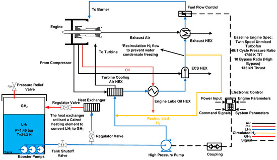
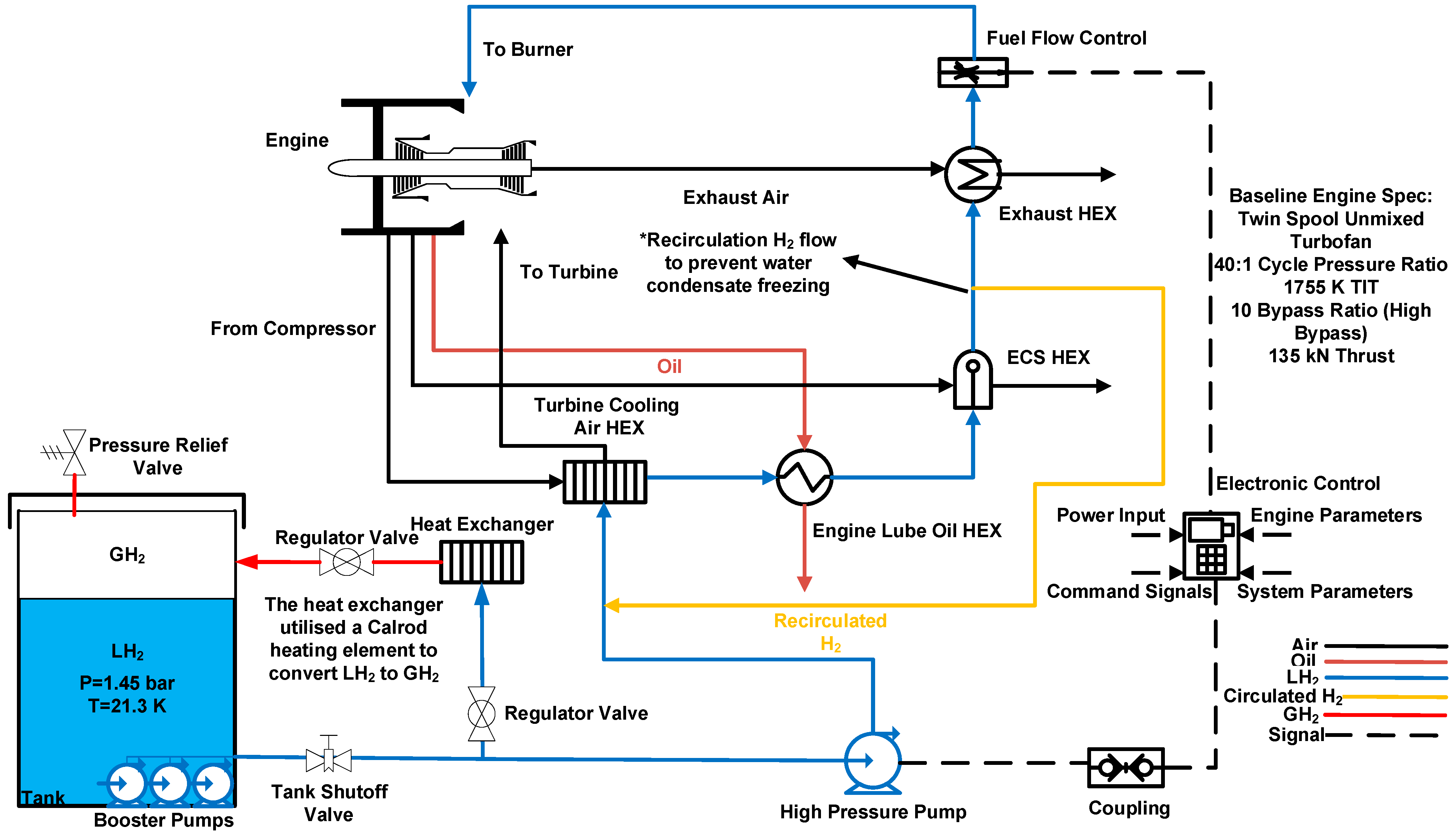
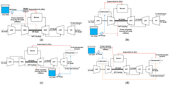
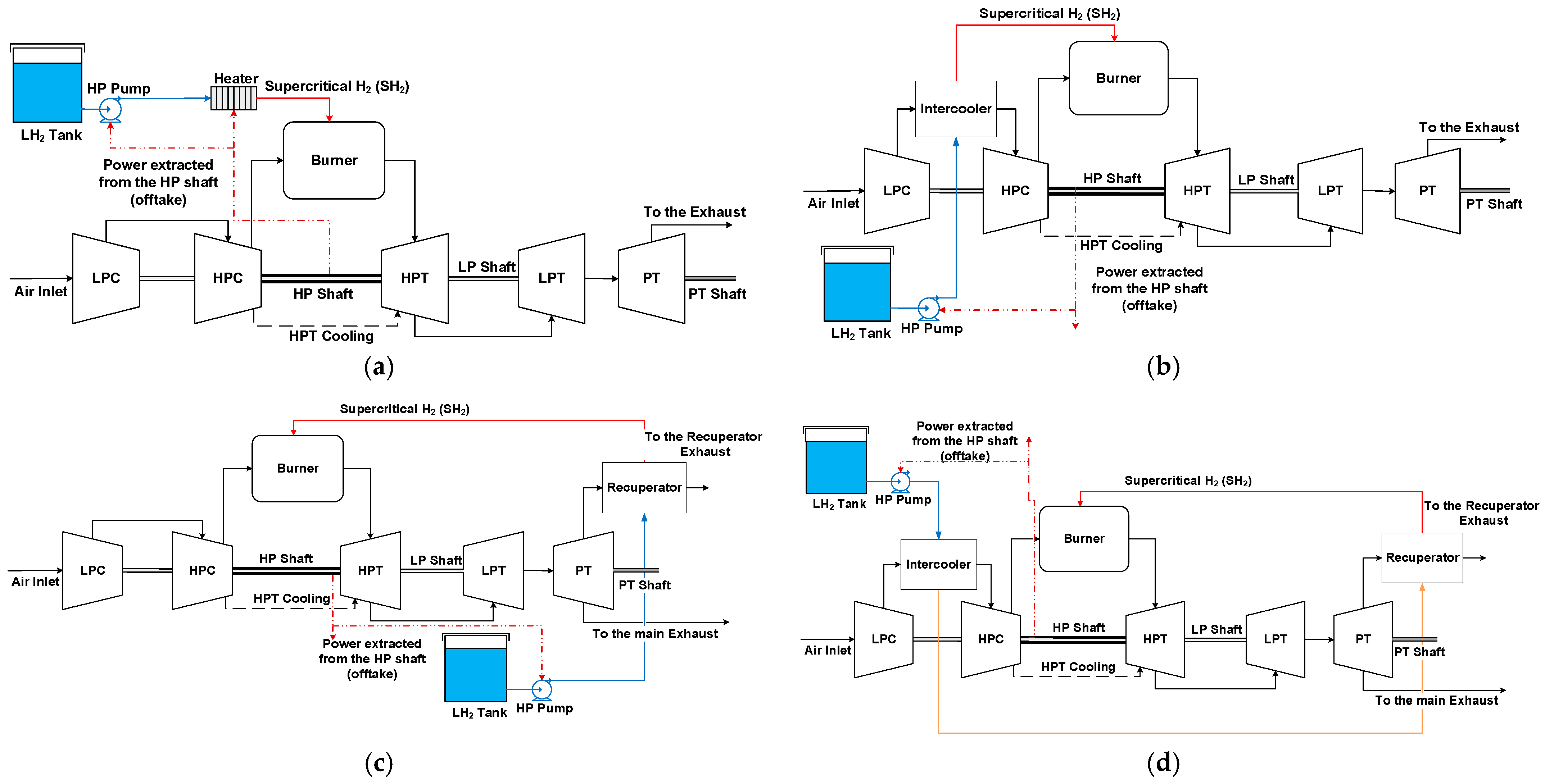
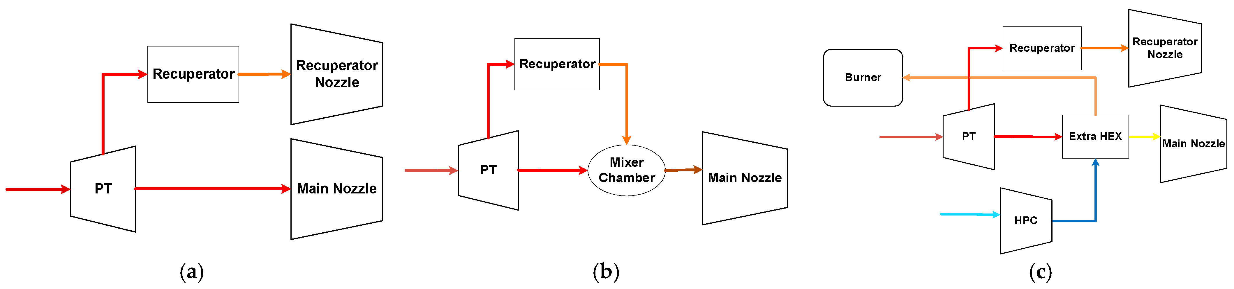
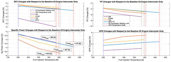
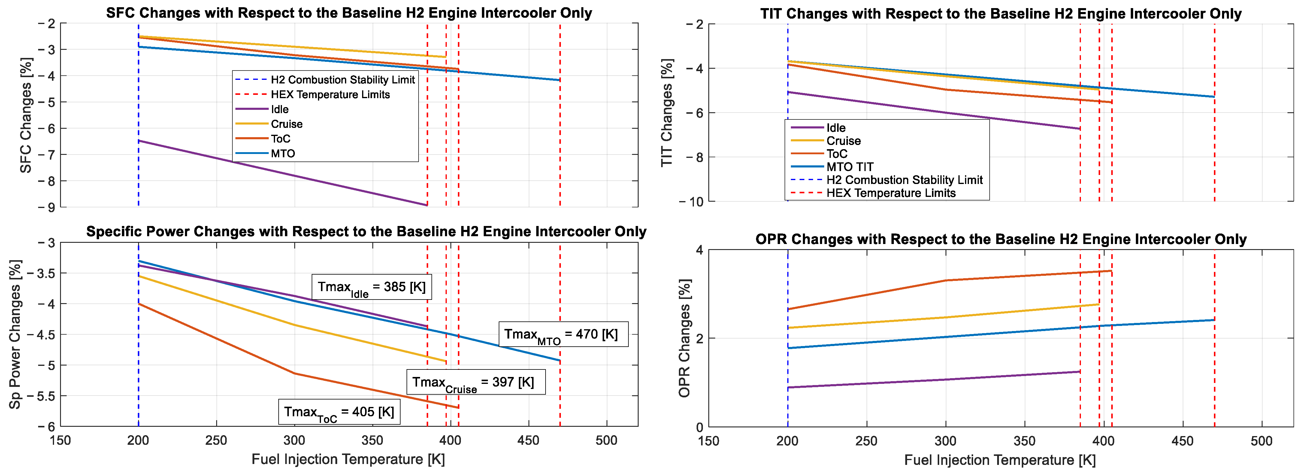
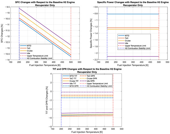
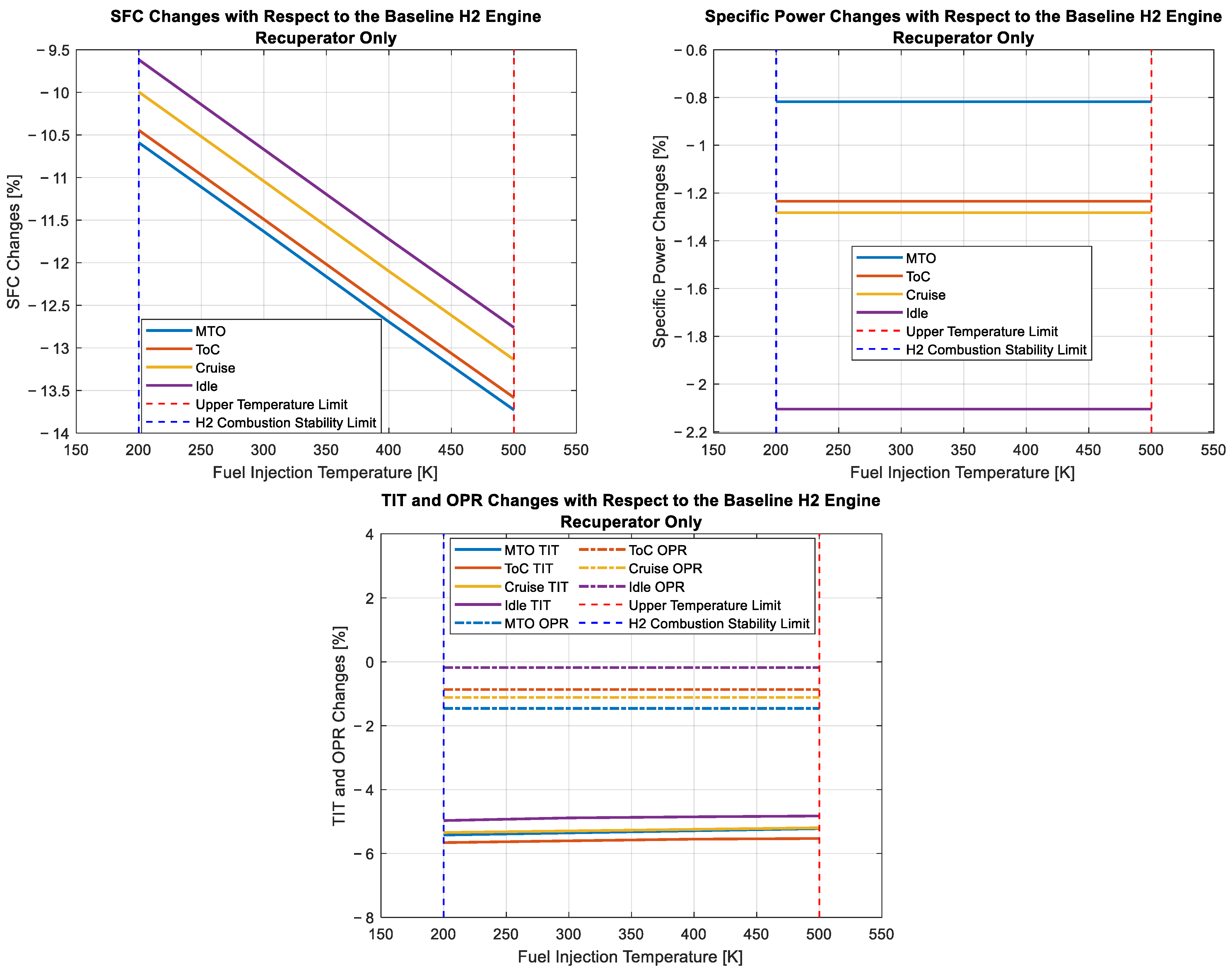
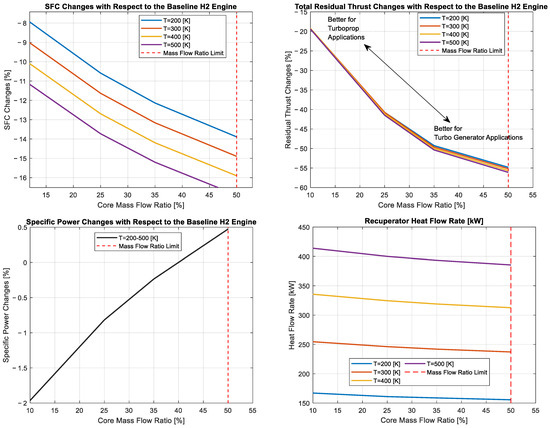

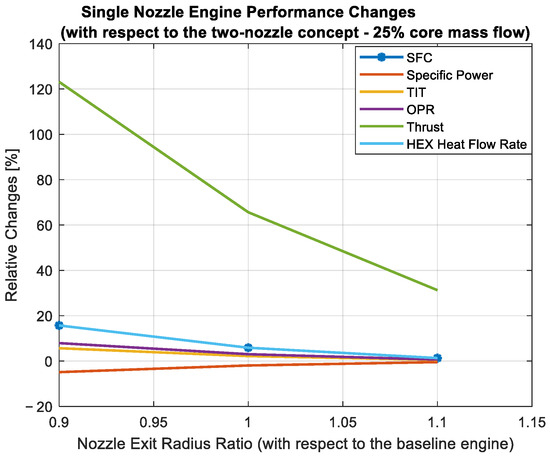
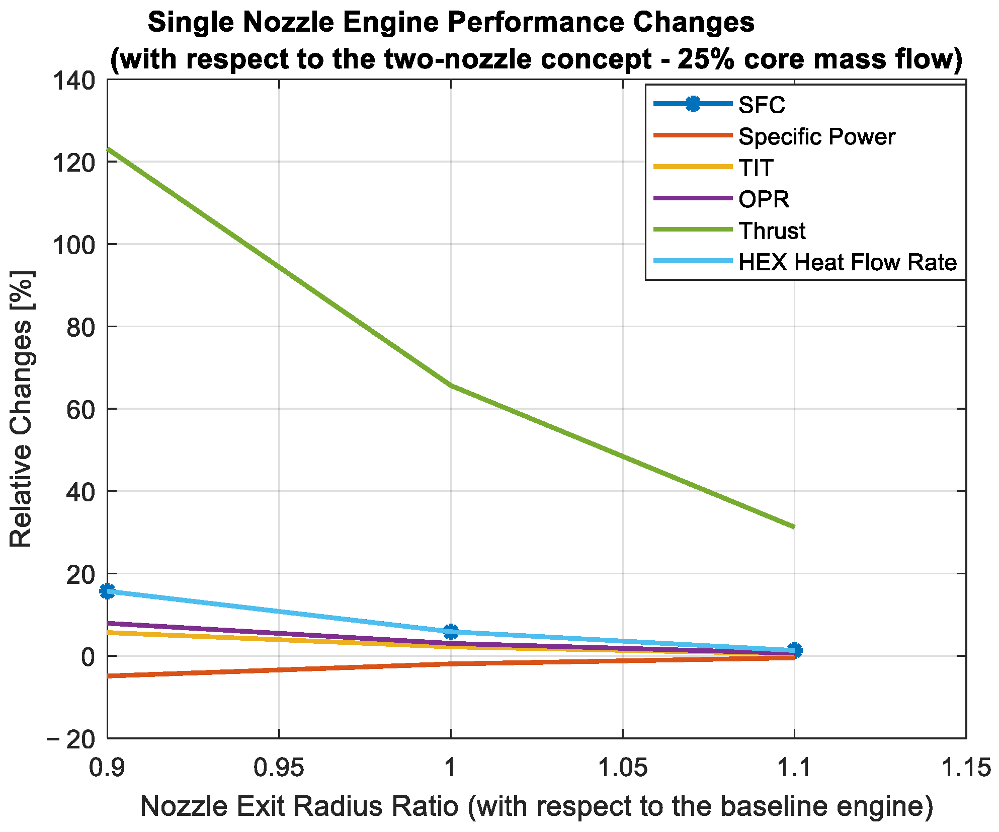
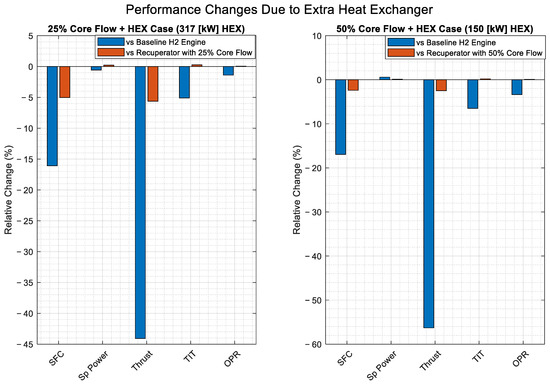
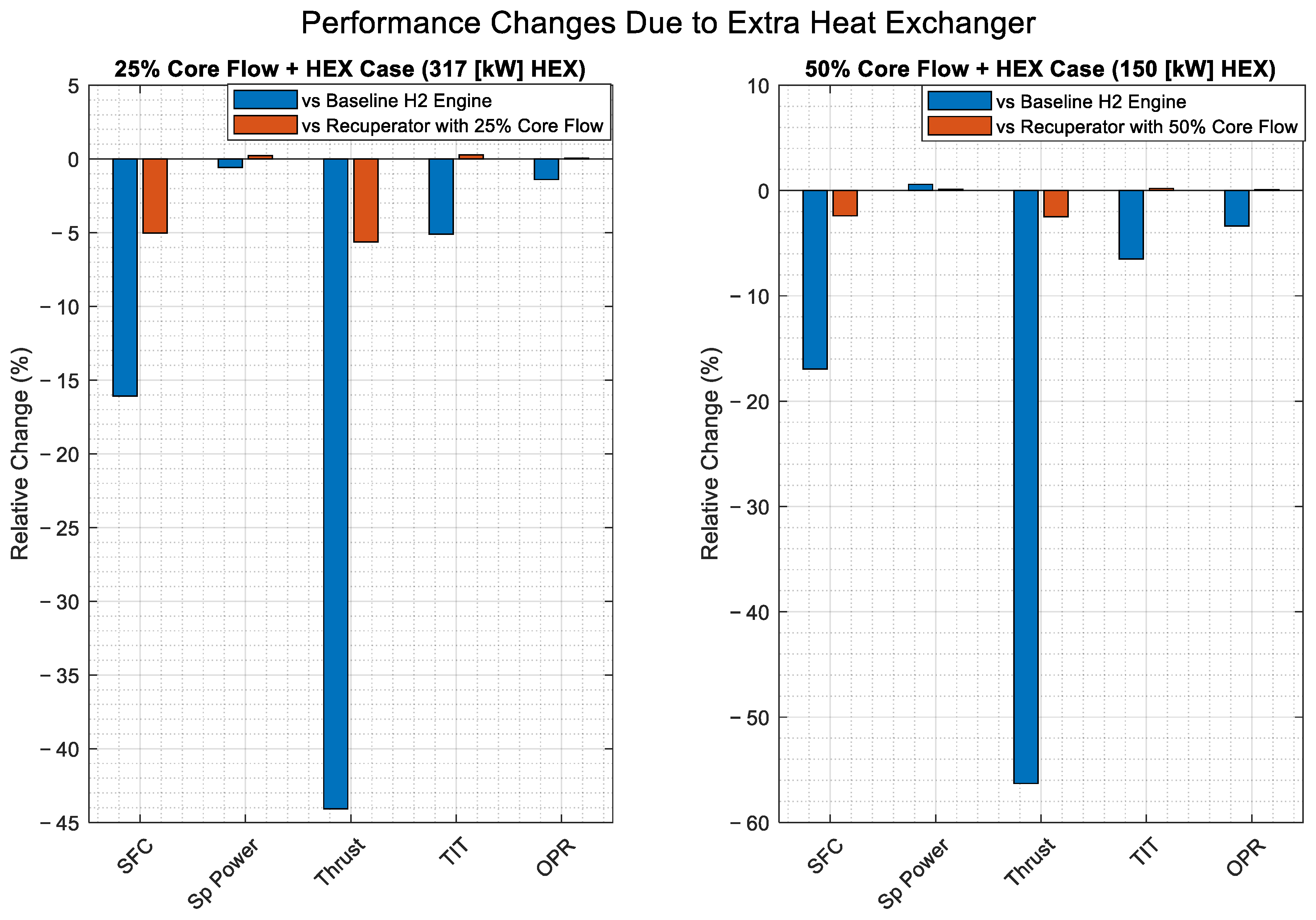
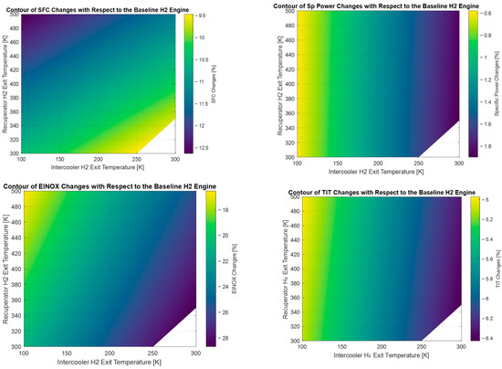
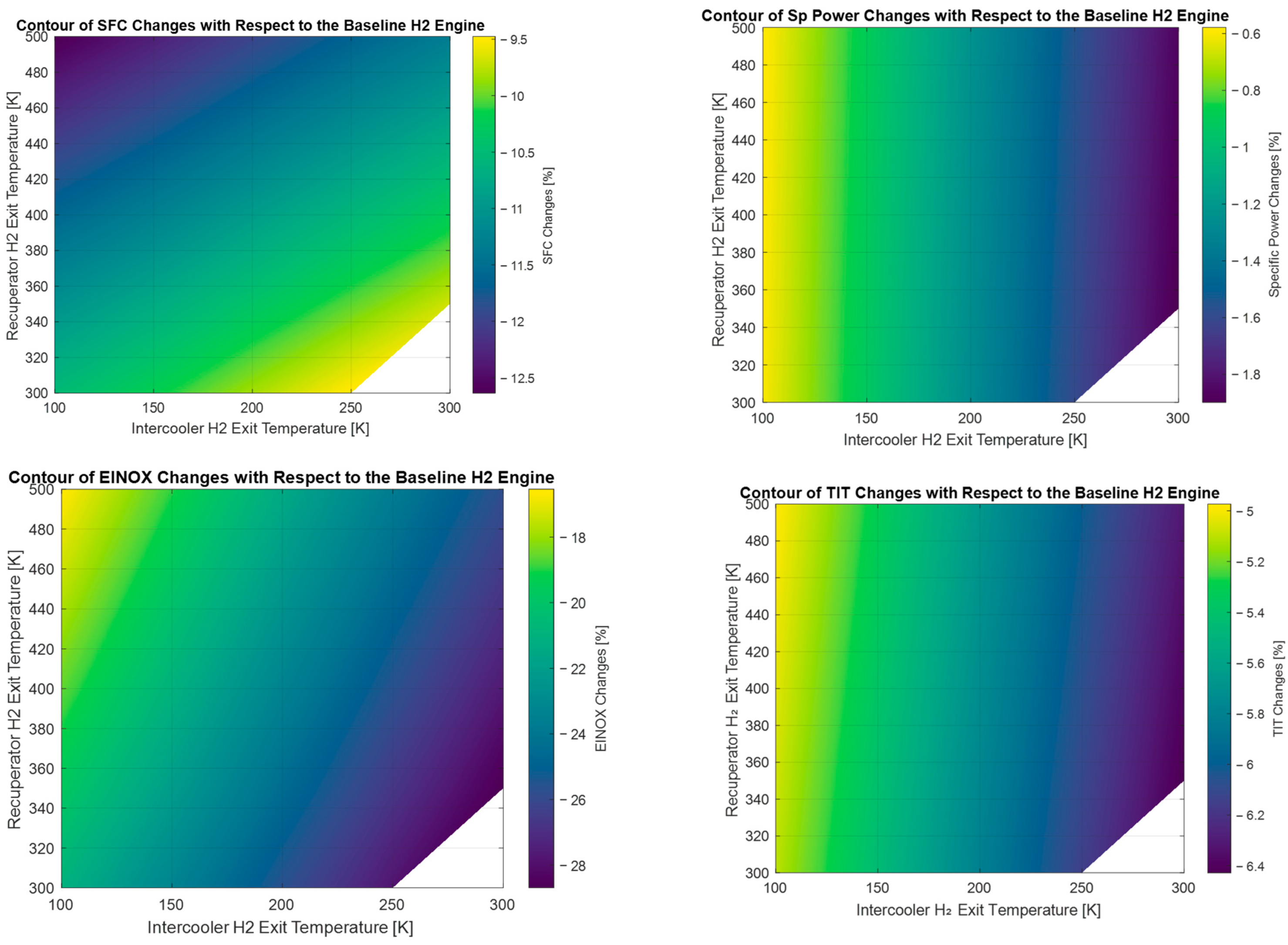
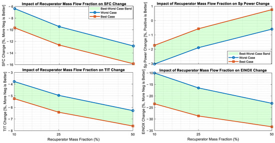
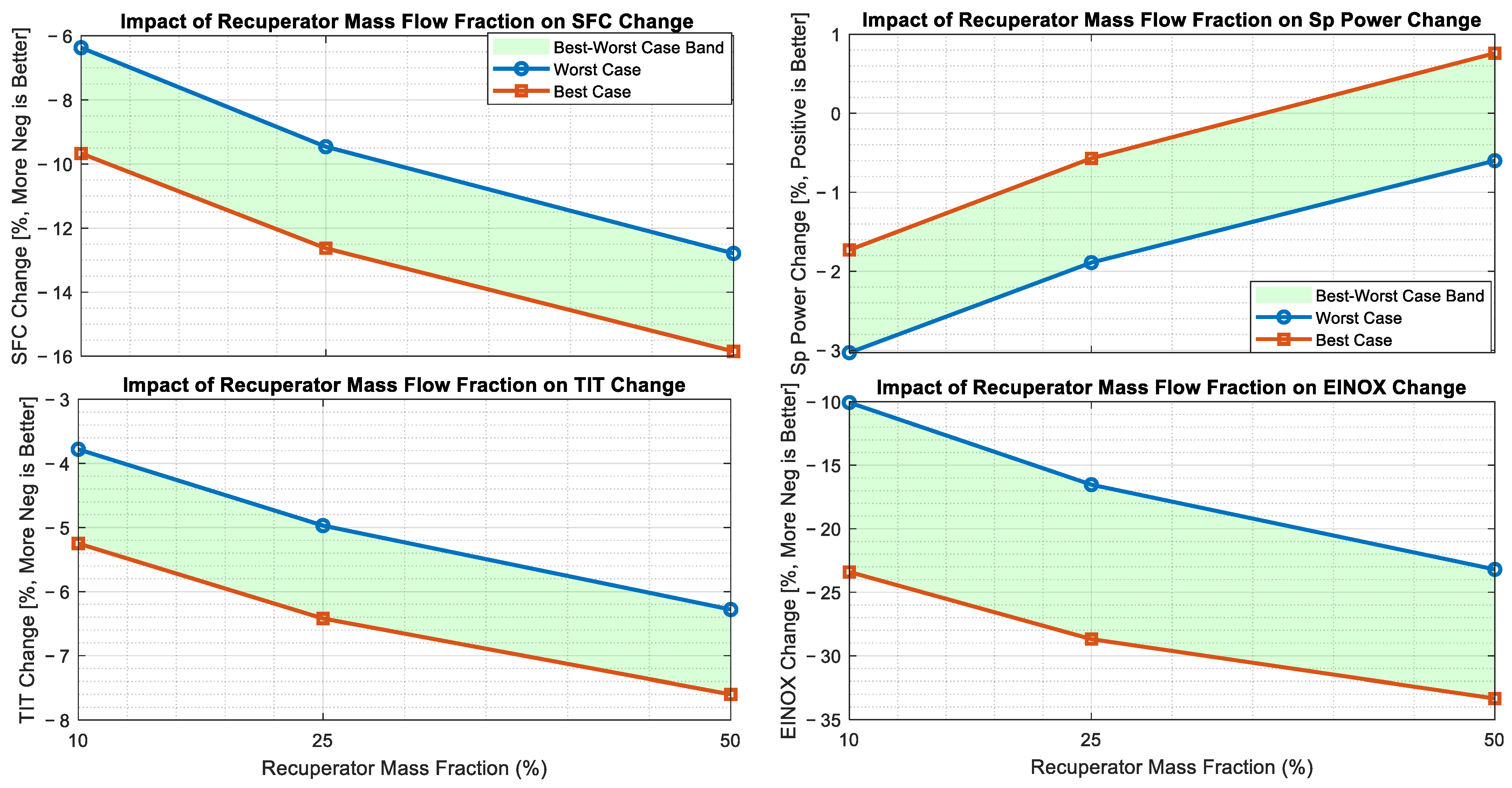
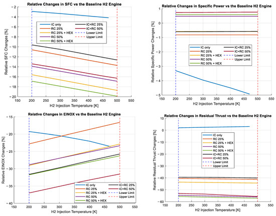
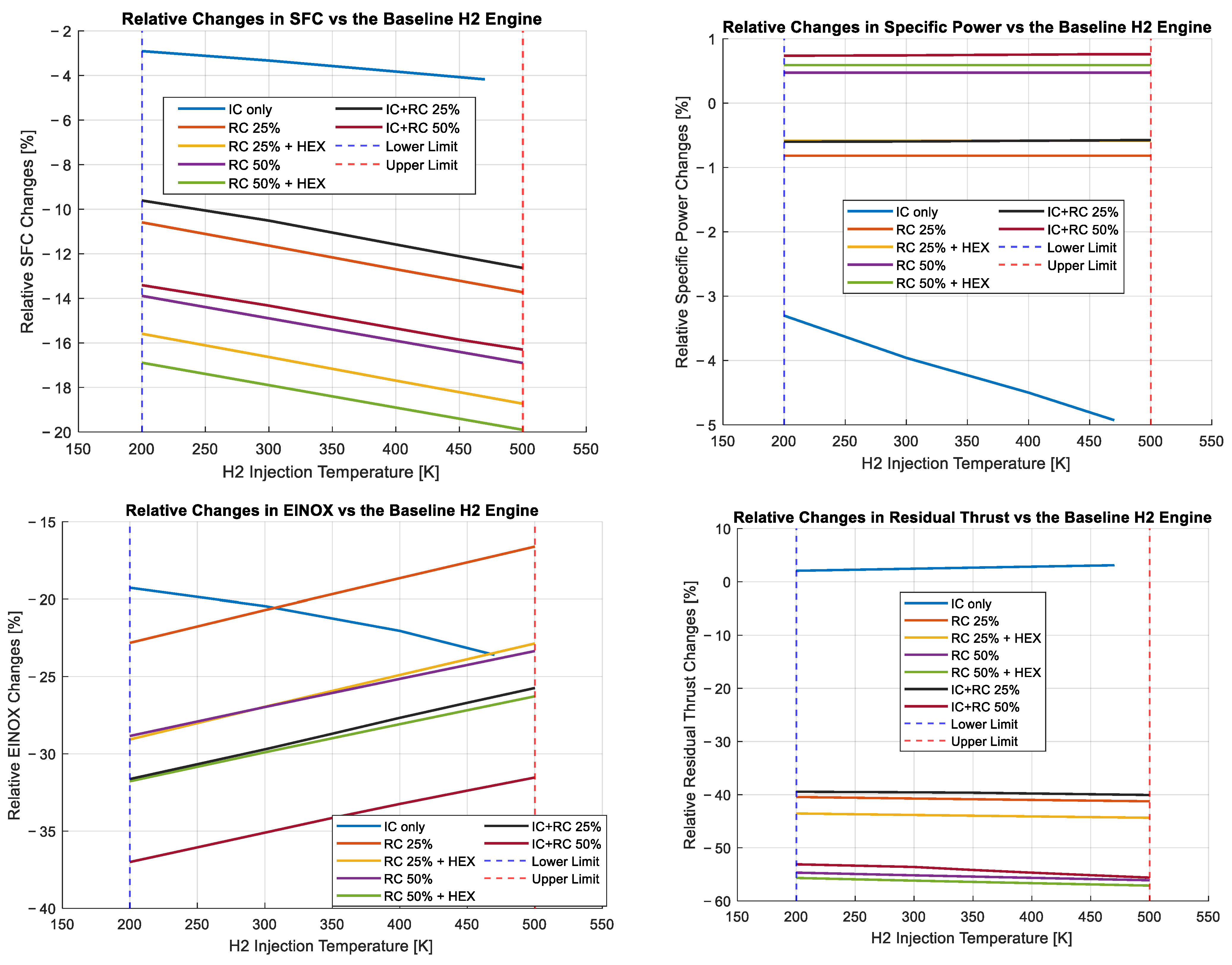
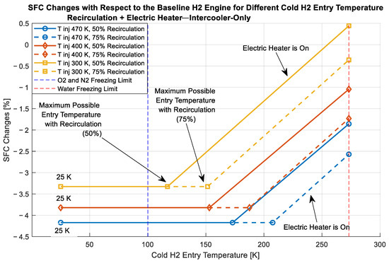
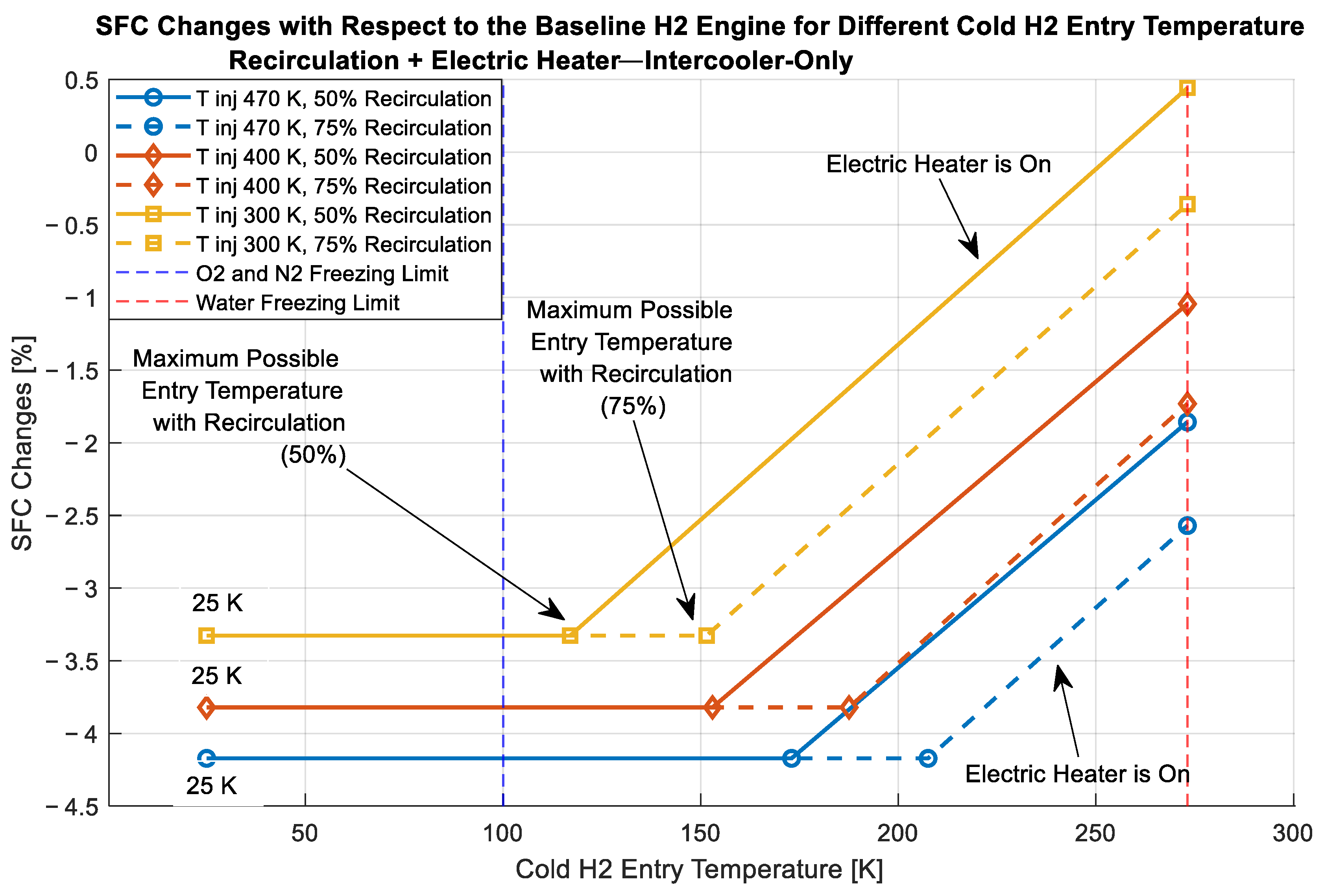

Disclaimer/Publisher’s Note: The statements, opinions and data contained in all publications are solely those of the individual author(s) and contributor(s) and not of MDPI and/or the editor(s). MDPI and/or the editor(s) disclaim responsibility for any injury to people or property resulting from any ideas, methods, instructions or products referred to in the content. |
© 2026 by the authors. Licensee MDPI, Basel, Switzerland. This article is an open access article distributed under the terms and conditions of the Creative Commons Attribution (CC BY) license.