


Abstract
The unplanned failure of the drive ring gear of a horizontal ball mill is one of the most severe unscheduled shutdowns a cement plant can face, since replacement lead times of 9–18 months make on-site repair the only viable option for maintaining production continuity. This paper reports an industrially validated emergency repair framework applied to a two-piece EN-GJS-800-2 nodular cast-iron ring gear (6531.50 mm pitch diameter, 216 teeth) affected by multiple cracks, including a 750 mm through-crack. Because the material combines high strength with markedly low ductility, five shielded metal arc welding (SMAW) procedure specifications (WPS 1–WPS 5) were developed and evaluated sequentially in the field over approximately thirteen months (December 2024–January 2026) while progressively varying preheating temperature (150–600 °C), joint geometry, filler metal chemistry, and mechanical restraint strategy. WPS 1 and WPS 2 were limited by, respectively, transverse post-weld cracking under the lower-preheat condition and severe geometric distortion (up to −2.8 mm radial run-out) from excessive restraint at 600 °C. WPS 3 and WPS 4 progressively introduced a root land, dissimilar ASTM A36 reinforcement plates, and post-weld heat treatment. WPS 5, a hybrid procedure combining nickel buttering (ENi-CI), a nickel–iron dissimilar filler (ENiFe-CI), and controlled interpass peening, produced no reported surface-breaking crack indications on post-weld liquid penetrant testing (PT) and preserved the corrected gear concentricity. During the distortion period, broadband root mean square (RMS) vibration velocity at the main bearing housings was reduced from 20 mm/s to 7 mm/s by temporarily lowering the ball-charge filling degree from 37% to 29% and production from 90 to 55 t/h. Following WPS 5, the repaired ring gear operated continuously for approximately three months, from October 2025 until the replacement gear was installed in January 2026. The results provide field-scale evidence, rarely documented in the open literature, on how welding procedure variables, geometric distortion, and operational vibration interact during the emergency repair of large gear components incorporating dissimilar materials.
1. Introduction
Horizontal ball mills rely on a large-diameter girth (ring) gear–pinion assembly mounted circumferentially on the mill shell to transmit the torque required for clinker grinding. This transmission is subjected to repeated tooth root bending, high flank contact stresses, load fluctuations, and abrasive contamination from cement and clinker dust. Over prolonged service, cyclic loading promotes fatigue crack initiation and propagation, while misalignment, geometric run-out, lubrication condition, particulate contamination, and thermal/environmental exposure can modify contact conditions and accelerate wear or fatigue damage [1,2,3,4]. These mechanical transmission demands make the girth gear a critical asset, and its dimensional integrity directly affects gear-mesh loading and vibration.
Failure of a girth gear is one of the highest-consequence events in a cement plant. Girth and ring gears in heavy rotating equipment are comparatively under-represented in the failure analysis literature relative to smaller power transmission gears, yet the documented cases consistently show that once cracking initiates in a perimetral gear body, the combination of large mass, high restraint, and continuous cyclic loading makes conventional repair strategies unreliable [2,5]. Original equipment replacement lead times for a girth gear of this size typically range from 9 to 18 months, a delay that is operationally and financially incompatible with continuous cement production. In this context, on-site weld repair combined with temporary structural reinforcement is often the only technically and economically viable path to preserve business continuity while a replacement is procured, consistent with the broader shift in industrial maintenance management towards rapid data-informed corrective response for critical rotating assets [6].
The metallurgical difficulty of this approach is substantial. EN-GJS-800-2 pearlitic nodular (ductile) cast iron combines a minimum tensile strength above 780 MPa with very low ductility (minimum elongation around 2%), a combination that is well suited to gear applications but poorly suited to fusion welding [7]. During welding, the thermal cycle dissolves graphite nodules adjacent to the fusion boundary; if the subsequent cooling rate is not adequately controlled, the resulting carbon-enriched heat-affected zone (HAZ) transforms into hard brittle martensite and massive carbides, creating preferential sites for cold cracking and hydrogen-assisted cracking [8,9]. The repair welding literature on ductile and nodular cast irons converges on nickel and nickel–iron filler metals as the preferred consumables. Nickel has negligible solid-state carbon solubility and does not form hard carbides, allowing a buttering layer to act as a diffusion barrier against carbon migration from the base metal [10,11,12]. Where the repaired cross-section must also restore structural stiffness, dissimilar joints to carbon-steel reinforcement (typically ASTM A36) using nickel–iron consumables are reported to accommodate the thermal expansion mismatch between the two materials [11,13].
A second frequently under-reported difficulty is geometric; welding of thick and highly restrained sections is a classical source of shrinkage-driven distortion and residual stress. The mitigation strategies documented for heavy steel and cast-iron repairs—controlled preheat and interpass temperature, short-bead sequencing, and immediate peening—are well established individually [11,14], but their combined effect on the dimensional integrity of a perimetral gear under high mechanical restraint is rarely quantified in the field. Because run-out and eccentricity in a girth gear mesh translate directly into impact loading and vibration once the mill returns to service, dimensional deviations introduced during repair welding are not just a metallurgical or cosmetic concern but can also propagate into the vibration signature used for plant condition monitoring. In this study, ISO 20816-3:2022 [15] is cited only as a general reference for broadband vibration evaluation; the reported values of 7 mm/s and 20 mm/s are plant-specific internal operating criteria, and are not presented as formal ISO zone boundaries. This is particularly relevant because the ring gear rotates at only 17 rpm and the required machine/support classification was not documented. Therefore, severe run-out may force a temporary reduction in production to keep the machine within the plant’s operationally acceptable vibration envelope.
The existing literature treats the three domains of cast-iron repair welding metallurgy, welding-induced distortion control, and vibration-based condition assessment of gear transmissions largely in isolation. Metallurgical studies on nodular cast-iron repair welding are typically conducted at the coupon or laboratory scale [8,9], while distortion control studies focus on generic steel weldments rather than large dissimilar gear bodies [14] and gear failure analysis case studies rarely report the iterative development of the repair procedure itself or its downstream operational consequences [2,5]. Largely absent from the open literature is a single, field-scale account that follows a girth gear repair from failure diagnosis through five successive welding procedure iterations to the resulting geometric and vibratory response of the operating machine while connecting each procedural change to its observed mechanical and operational consequences.
This paper addresses the above gap by reporting the complete development and industrial validation of an emergency repair framework for a cracked EN-GJS-800-2 ball mill ring gear, structured around the causal chain: failure diagnosis → iterative WPS development → thermal and metallurgical response → geometric/distortion response → vibration response → operational mitigation → industrial validation. The primary novelty of this work is not a new welding process but the field-scale integration and quantitative documentation of five successive SMAW procedures, their metallurgical and geometric outcomes, and their direct link to the broadband RMS vibration-based operational response of the mill, evaluated through a year-long iterative repair campaign and a final approximately three-month continuous-service validation of WPS 5. The specific contributions are: (i) a documented sequential WPS development history showing how preheating, joint geometry, filler metal selection, and mechanical restraint jointly determine whether a repair fails by cracking or by distortion; (ii) field-scale quantification of the relationship between welding-induced run-out and mill vibration severity; and (iii) a demonstrated operational mitigation strategy (controlled reduction of ball charge and throughput), which enabled restricted operation during the repair campaign and approximately three months of continuous service after WPS 5 until the replacement gear was installed.
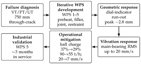
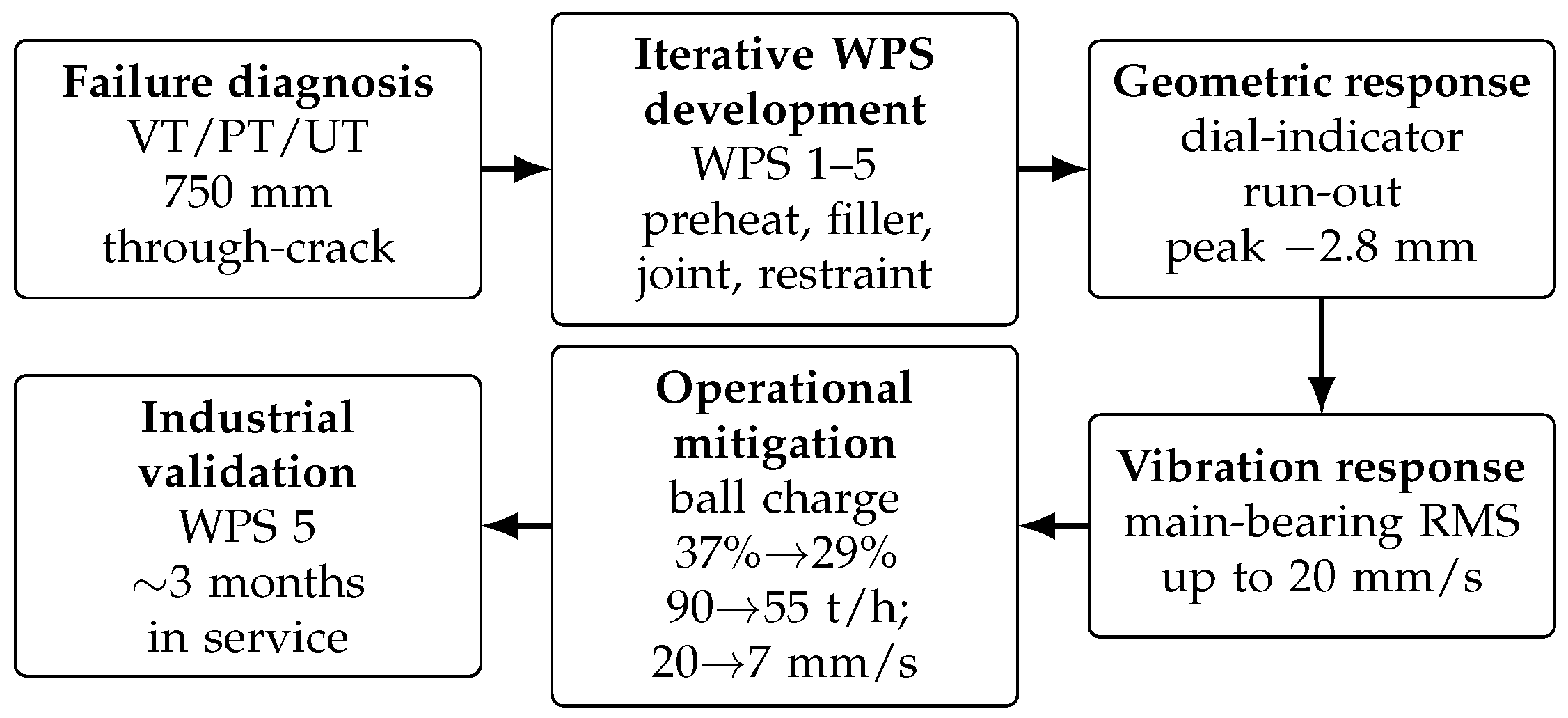
Figure 1 summarizes the evidence chain used to organize the field observations and to distinguish the measured response variables from literature-supported metallurgical interpretation.
Figure 1.
Industrially validated emergency repair framework used to organize the field evidence. Boxes report observed or measured stages and variables; metallurgical mechanisms discussed later are treated as literature-supported interpretations where direct microstructural evidence was unavailable.
2. Materials and Methods
2.1. Industrial System and Failure Context
The study component is the girth (ring) gear of a horizontal tubular ball mill operating in a cement plant in central Ecuador. The gear is manufactured in two half-sections cast in EN-GJS-800-2 pearlitic nodular iron, with a pitch diameter of 6531.50 mm, a face width of 810 mm, 216 teeth, a module of 30 mm, and a nominal operating speed of 17 rpm. The exact commissioning date and cumulative operating hours of the considered gear were not available in the maintenance records supplied for this study, so a total pre-failure service life value cannot be reported reliably. The documented repair campaign itself extended from December 2024 to January 2026, and the final WPS 5 repair remained in continuous service for approximately three months before planned replacement. During a scheduled preventive maintenance inspection in the first week of November 2024, a through-crack was identified at tooth 197. A predictive work order was subsequently issued, and the finding triggered the emergency repair programme reported here.
2.2. Initial Damage Assessment
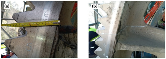
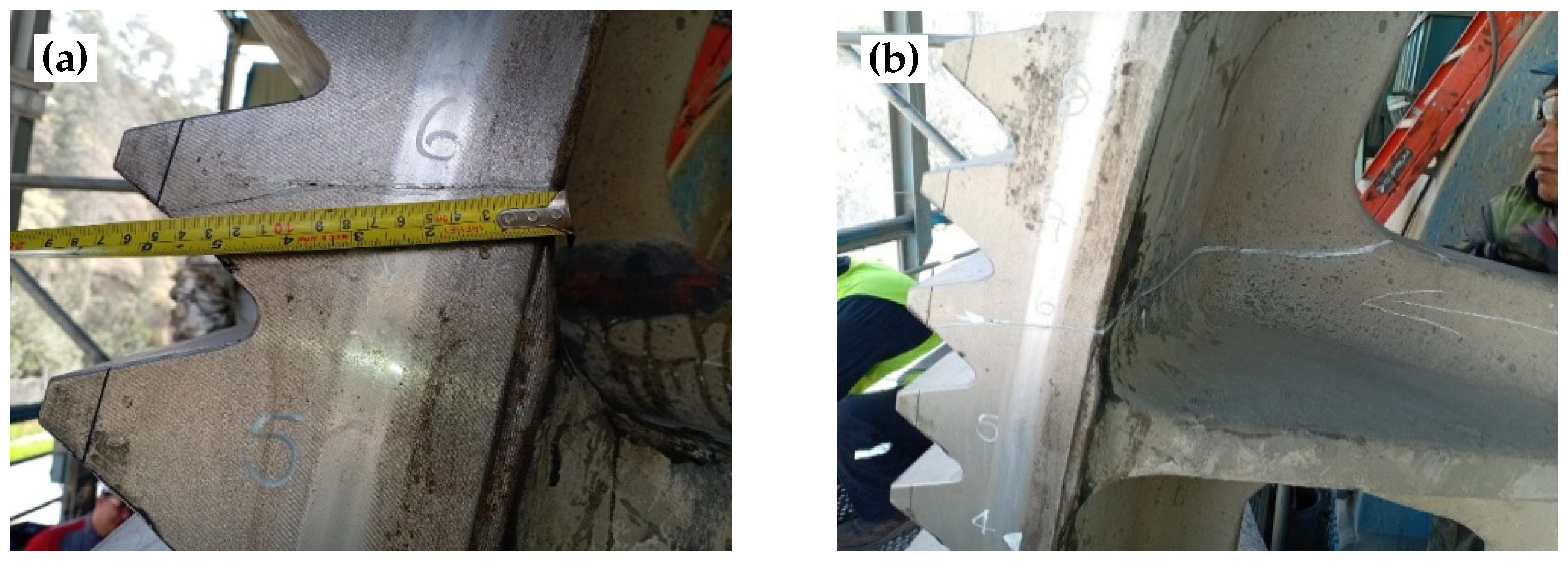
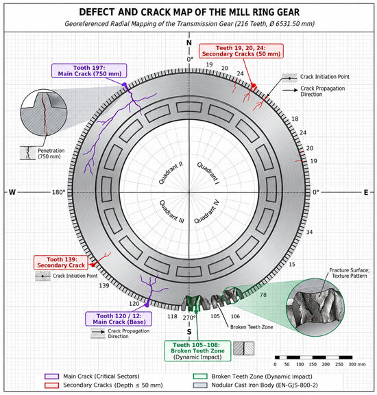
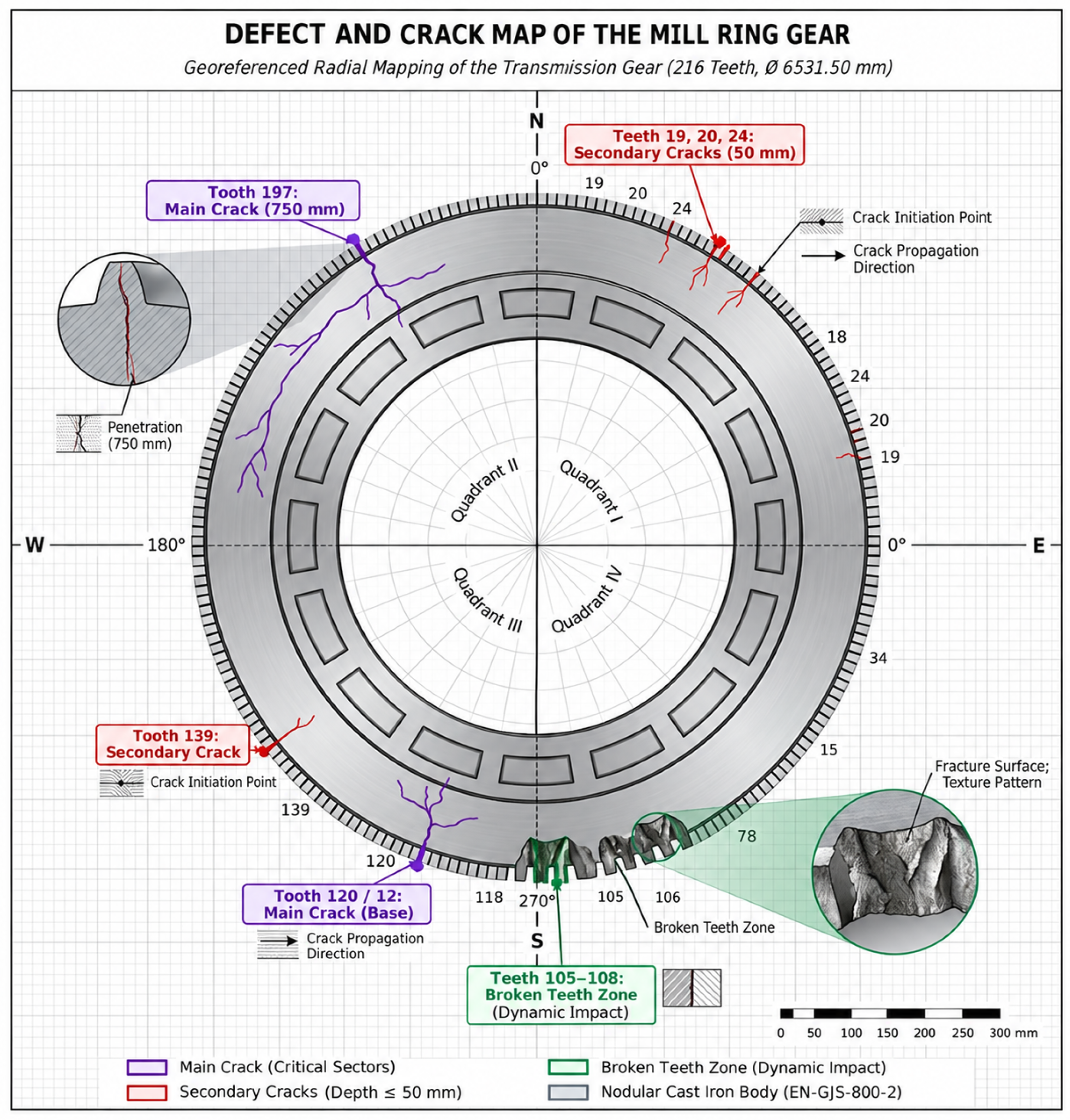
Failure severity was characterized with a sequential non-destructive testing (NDT) protocol: visual inspection (VT) with magnifying optics for surface mapping; fluorescent liquid penetrant testing (PT) under ultraviolet light to characterize surface crack branching; and pulse-echo ultrasonic testing (UT) with 4 MHz, 45°/70° angle-beam transducers to determine through-thickness depth and trajectory. For reporting purposes, the detected discontinuities were classified by extent and location as follows: (i) a primary 750 mm through-crack associated with tooth 197; (ii) a second major/root crack in the tooth 120 sector; and (iii) secondary surface/subsurface cracks at teeth 19, 20, 24, and 139, with local depths up to approximately 50 mm (Figure 2 and Figure 3). This is a field NDT-based classification rather than a fracture mechanism classification. Excavated material at the root of the largest crack showed porosity that could plausibly have contributed to crack initiation; the finding was forwarded to the original gear manufacturer, but no formal metallurgical report or documented causal hypothesis was made available to the authors. Therefore, porosity is reported only as an observed discontinuity and is not assigned as the demonstrated root cause of failure.
Figure 2.
Representative damage identified during the initial inspection: (a) through-crack and (b) secondary cracking on the ring gear teeth. Source: plant preventive maintenance department.
Figure 3.
Radial defect map of the ring gear (216 teeth, 6531.50 mm pitch diameter) obtained from the combined VT/PT/UT inspection, showing the location, approximate length, and classification of all identified cracks. Source: plant preventive maintenance department.
2.3. Environmental Confinement and Baseline Thermal Control
The first major intervention was carried out during a scheduled plant shutdown (December 2024–January 2025) within a 21-day operating window. The mill was chocked, aligned, and secured in a safe working position. Independent scaffolding was erected as a personnel access structure around the gear, and remained mechanically isolated from the mill body; it did not support the thermal enclosure or act as a structural restraint on the gear. A separate sealed enclosure of fire-resistant tarpaulins surrounded the local work zone to suppress cross-drafts and reduce uncontrolled convective heat loss. The enclosure, insulation blankets, and localized torch heating together constituted the thermal control environment. The thermal control protocol common to all five welding procedures comprised: (i) passive insulation with silica fiber and glass wool thermal blankets over the HAZ and tooth mass; (ii) active heating with high-output liquefied petroleum gas (LPG) torches (“dragons”) for pre- and post-heating to minimize radial thermal gradients; and (iii) consumable conditioning, with all covered electrodes re-dried and held in portable ovens at 100–150 °C throughout every procedure to remove moisture, minimize diffusible hydrogen, and prevent hydrogen-induced cold cracking (HIC).
2.4. Joint Preparation
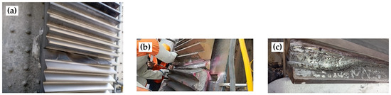
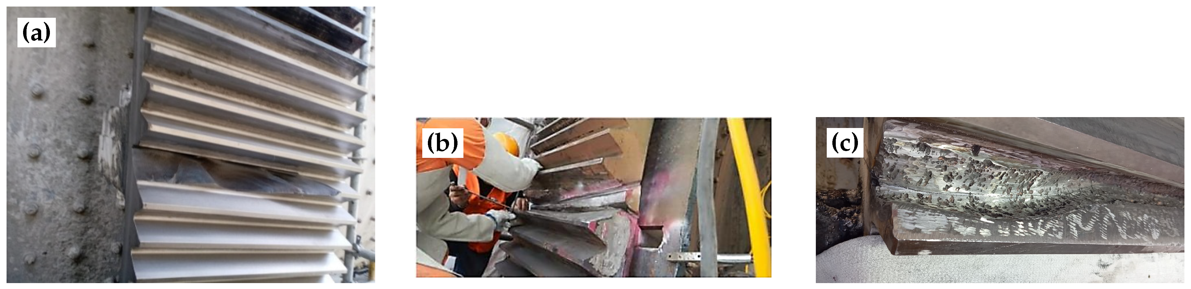
Fatigued and micro-cracked material was removed by mechanical excavation with abrasive cutting and grinding discs; the crack root porosity noted in Section 2.2 was identified at this stage. Complete crack tip removal was verified by follow-up PT inspection. Non-through cracks on tooth flanks were prepared by high-speed milling with tungsten-carbide cutters (Figure 4).
Figure 4.
Mechanical excavation and joint preparation prior to welding: (a) field excavation, (b) prepared joint geometry, and (c) field condition after material removal. Source: plant preventive maintenance department.
2.5. Welding-Procedure Development Strategy (WPS 1–5)
Following joint preparation, five successive SMAW welding procedure specifications were designed and applied in the field between December 2024 and October 2025, using high-toughness proprietary consumables from three suppliers (SAGER, MESSER, AGA), classified under the AWS A5.15/A5.15M nickel and nickel-alloy cast-iron electrode designations (ENi-CI, ENiFe-CI) [16], with electrode selection and current ranges following the suppliers’ technical data sheets for this specific repair [17]. The metallurgical selection logic was interface-specific rather than brand-specific: ENi-CI (high-Ni) was used where a ductile and machinable buttering/reconstruction layer and reduced carbon transfer from the cast iron were priorities; ENiFe-CI was selected for cast iron-to-A36 dissimilar interfaces, since the Ni–Fe deposit provides greater load-carrying capacity while retaining compatibility with ductile iron; and low-hydrogen E7018 was restricted to A36 steel-to-steel joints, where a ferritic structural steel consumable was appropriate. Each procedure was evaluated against and modified in response to the outcome of the previous one in order to identify the combination of preheat, joint geometry, filler metal chemistry, and mechanical restraint that minimized both HAZ embrittlement and angular/circumferential distortion of the gear. The independent (process) variables varied across the five procedures were the preheating temperature, joint/bevel geometry, root face configuration, filler metal chemistry, use of dissimilar ASTM A36 reinforcement, use of mechanical restraint (“strongbacks”), and post-weld heat treatment (PWHT). The response variables monitored were post-weld cracking/recracking (by PT), radial/axial run-out (by dial indicator survey), and once the mill returned to service, RMS vibration velocity at the main bearing housings. The ball charge filling degree (%J) denotes the volumetric fraction of the mill internal working volume occupied by the grinding media charge, expressed as a percentage; throughput denotes the cement production mass flow rate through the mill, expressed in t/h. Table 1 summarizes the five procedures in chronological order.
Table 1.
Evolutionary matrix of the five welding procedure specifications (WPS) applied to the ring gear.
A protocol common to every procedure controlled interpass conditions: slag was removed and each deposited bead (maximum length 50 mm) was immediately pneumatically peened with needle scalers to convert near-surface tensile residual stress into beneficial compressive stress, followed by cleaning with a wire brush. Interpass temperature was held between 180 and 250 °C using calibrated infrared pyrometers, with localized torch reheating below 180 °C and glass wool covering above 250 °C to slow cooling.
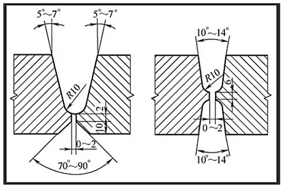
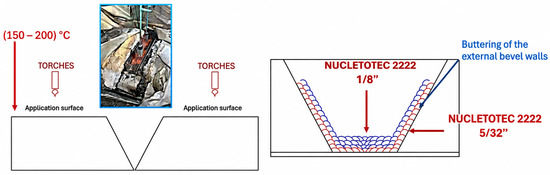
WPS 1 (SAGER, double-U bevel, evaluative): Applied during the December 2024–January 2025 shutdown to the largest through-crack. Parameters: direct current (DC), 95–100 A (1/8 in electrodes) and 110–120 A (5/32 in electrodes), consumables NUCLEOTEC 2222 and XUPER 2222 XHD; localized preheat 150–200 °C; double-U bevel at 70° included angle (Figure 5 and Figure 6); interpass peening.
Figure 5.
Double-U bevel geometry (70° included angle) used in WPS 1.
Figure 6.
Schematic of the WPS 1 repair sequence.
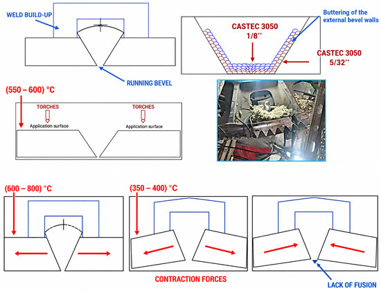
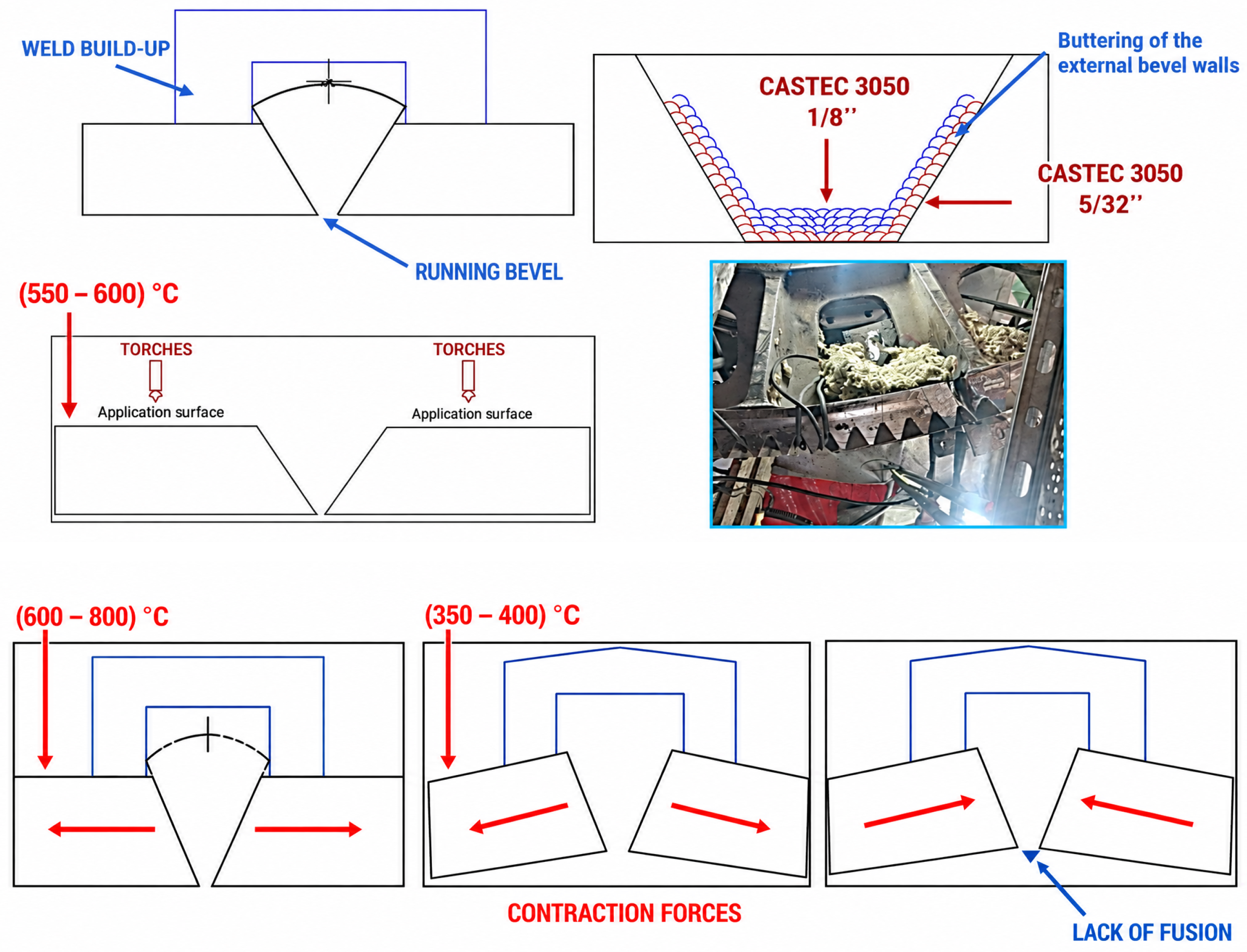
WPS 2 (SAGER, elevated preheat and mechanical restraint): Applied in March 2025 (15-day window) after WPS 1 recracking. The previously deposited weld metal was removed by abrasive gouging, leaving a wide-root butt preparation. Modifications: A copper backing bar was installed at the root as a heat sink; consumables were changed to the CASTEC 3050/3055 line at the same current ranges; preheating was raised to 550–600 °C using additional torches and a refractory brick enclosure; and rigid 1.5-in-thick ASTM A36 “strongback” restraint elements were welded across the joint to limit angular distortion (Figure 7). Because a component preheated to 600 °C requires extended safe working exposure for welders, additional occupational controls were implemented: radiant heat screens exposing only the active joint, localized forced ventilation directing hot air away from the welder without disturbing the flow of shielding gas, and mandatory hydration and rotation of welders within a maximum 30–40 min exposure window, consistent with recommended occupational heat stress management practice for workers performing precision manual tasks near high-temperature components [18,19].
Figure 7.
WPS 2 configuration: copper backing bar and ASTM A36 strongback restraint elements (top); resulting shrinkage force pattern at the restraint elements (bottom).
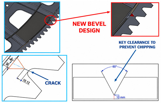
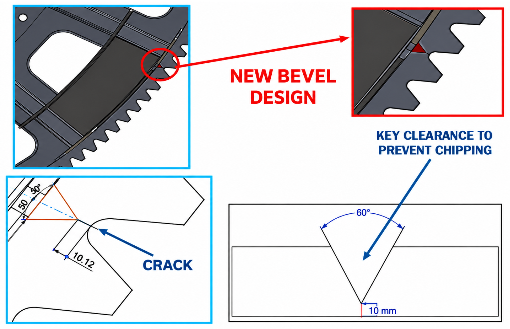
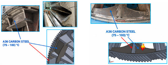
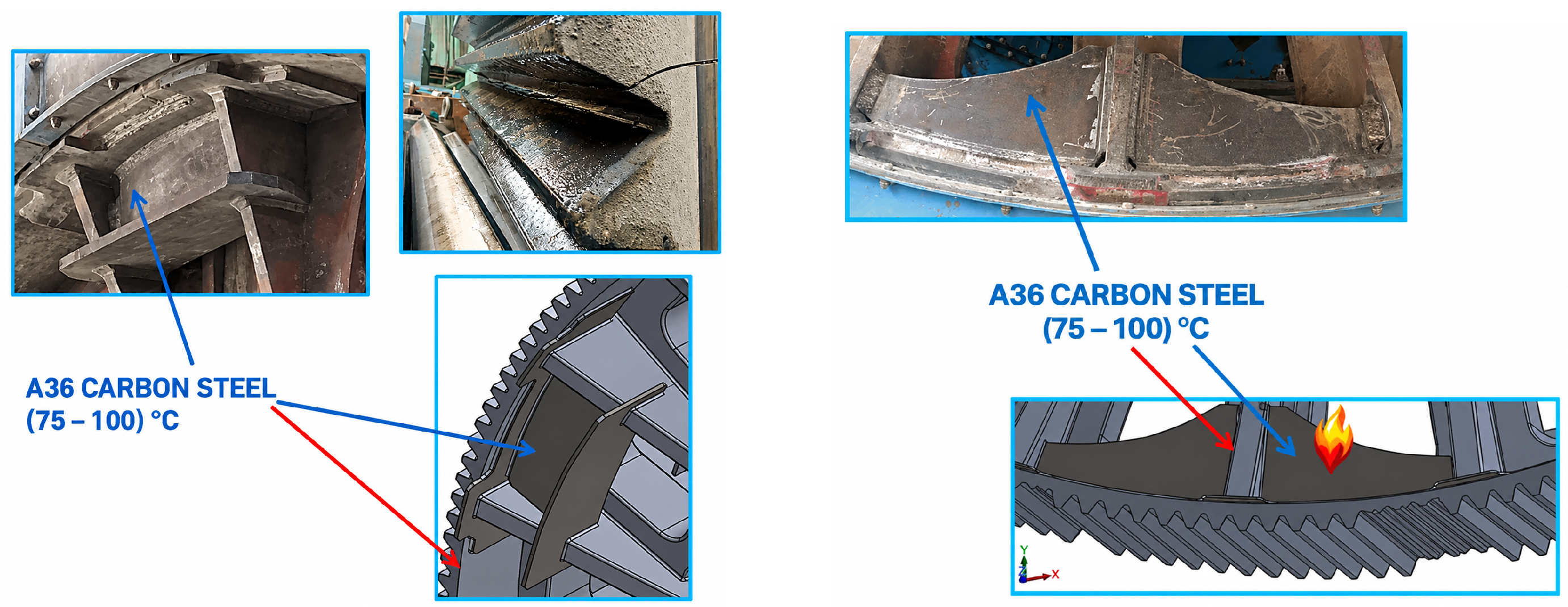
WPS 3 (MESSER, redesigned joint and structural reinforcement): Applied in May 2025 (15-day window) after the distortion observed under WPS 2 (see Section 3). Modifications: A 10 mm root land (mechanical land/root face) was introduced to provide rigid resistance against transverse shrinkage (Figure 8); deposition used short alternating beads (20–50 mm, back-step technique) at DC 22–28 V, 95–100 A (1/8 in) and 110–120 A (5/32 in); preheating was moderated to 150–200 °C with tent confinement and glass wool insulation. Dissimilar ASTM A36 structural reinforcement plates were designed and welded to the affected sector using differential preheating (150–200 °C on the cast-iron body, 75–100 °C on the A36 plates): a high-nickel electrode (MG E NiCl, ∼95% Ni) was used on the cast-iron side to maximize deposit ductility, and a nickel–iron electrode (MG E NiFeCl, ∼54% Ni/45% Fe) was used at the dissimilar A36-to-nodular iron interface to accommodate differential thermal expansion (Figure 9).
Figure 8.
Redesigned bevel geometry with a 10 mm root land introduced in WPS 3.
Figure 9.
Dissimilar ASTM A36 structural reinforcement applied in WPS 3.
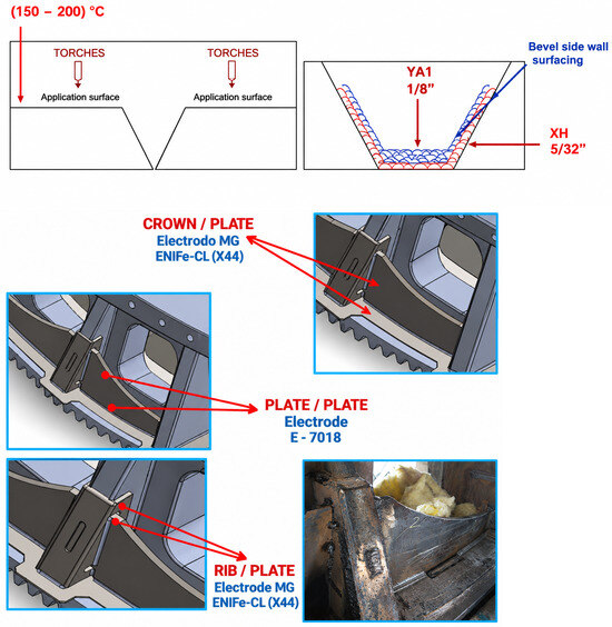
WPS 4 (AGA, multilayer scheme with post-weld stress-relief/controlled-cooling treatment): Applied in July 2025 (15-day window) to address the localized secondary cracking observed after WPS 3. Parameters: DC 22–28 V, 110–120 A (5/32 in electrodes); short beads (20–50 mm) with immediate peening; V-bevel at 60–70°, root opening and root face of 0 to 1/8 in; preheat 150–200 °C. Consumable selection was differentiated by interface: ENiFe-CI (AGA X41, ∼54% Ni) at the rib-to-reinforcement plate and gear-to-plate interfaces; low-hydrogen AWS E7018 for plate-to-plate (A36) unions; and pure nickel ENi-CI (AGA X44, ∼95% Ni) for tooth reconstruction to permit subsequent machining of the involute profile (Figure 10). After deposition, the intervened zone was uniformly raised to 300 °C, held for a minimum of 10 min, and then fully encapsulated in glass wool blankets for controlled slow cooling (<20 °C/h). Because 300 °C is below conventional full metallurgical PWHT temperatures for ferrous alloys, this field step is described here more precisely as a low-temperature post-weld stress relief/controlled cooling treatment rather than as a full metallurgical PWHT cycle.
Figure 10.
WPS 4 bevel design and multilayer application sequence.
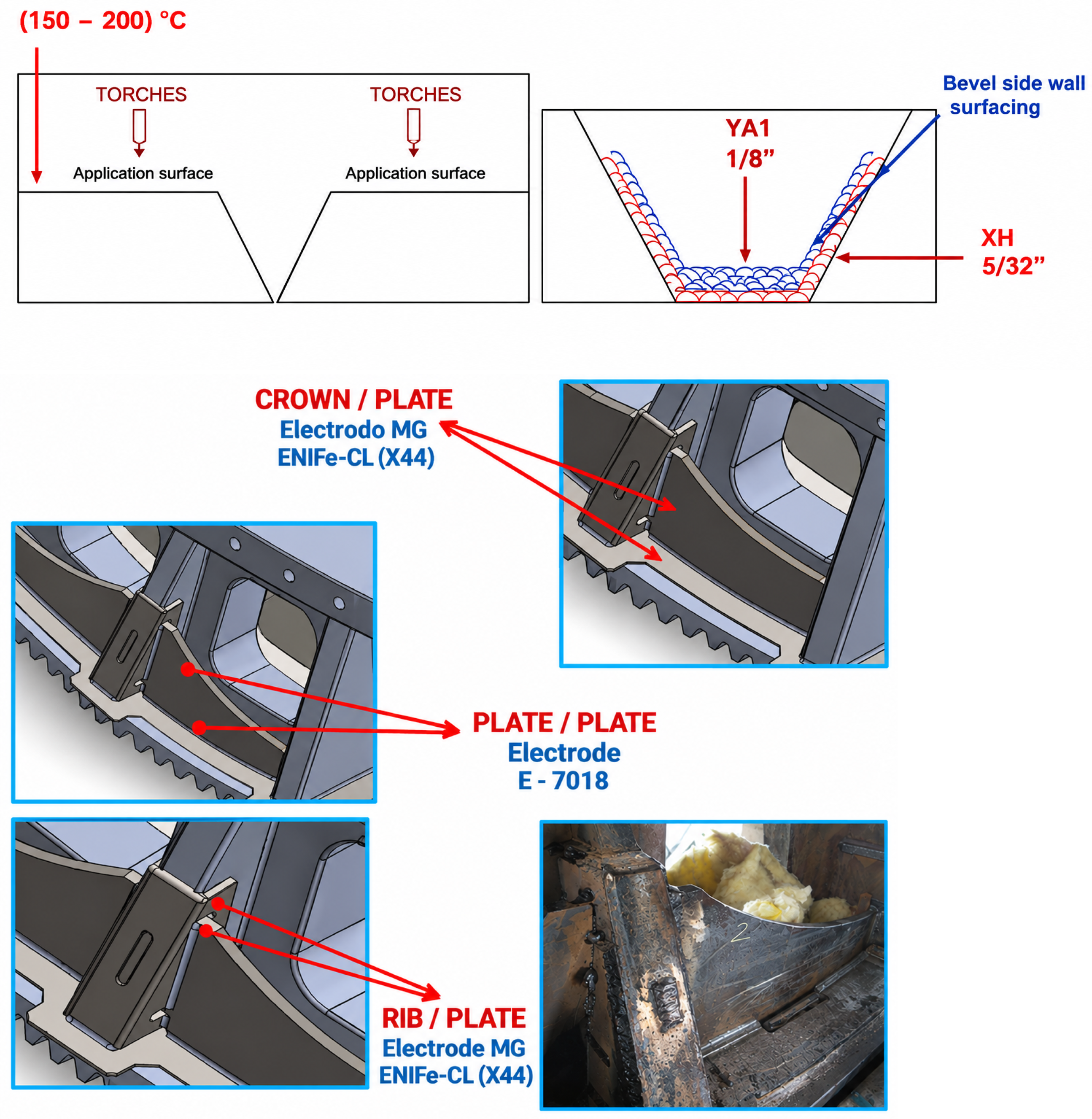
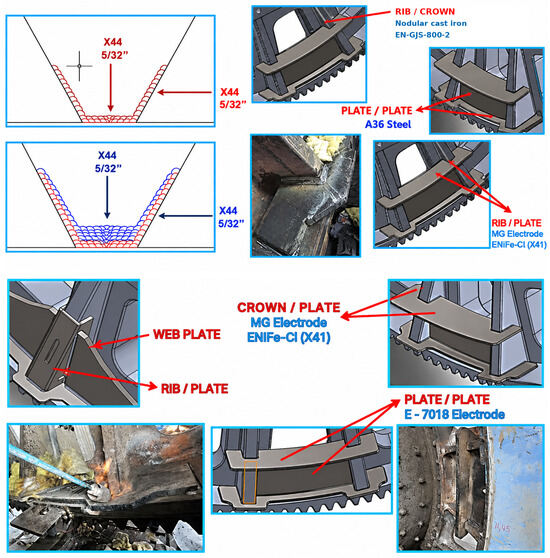
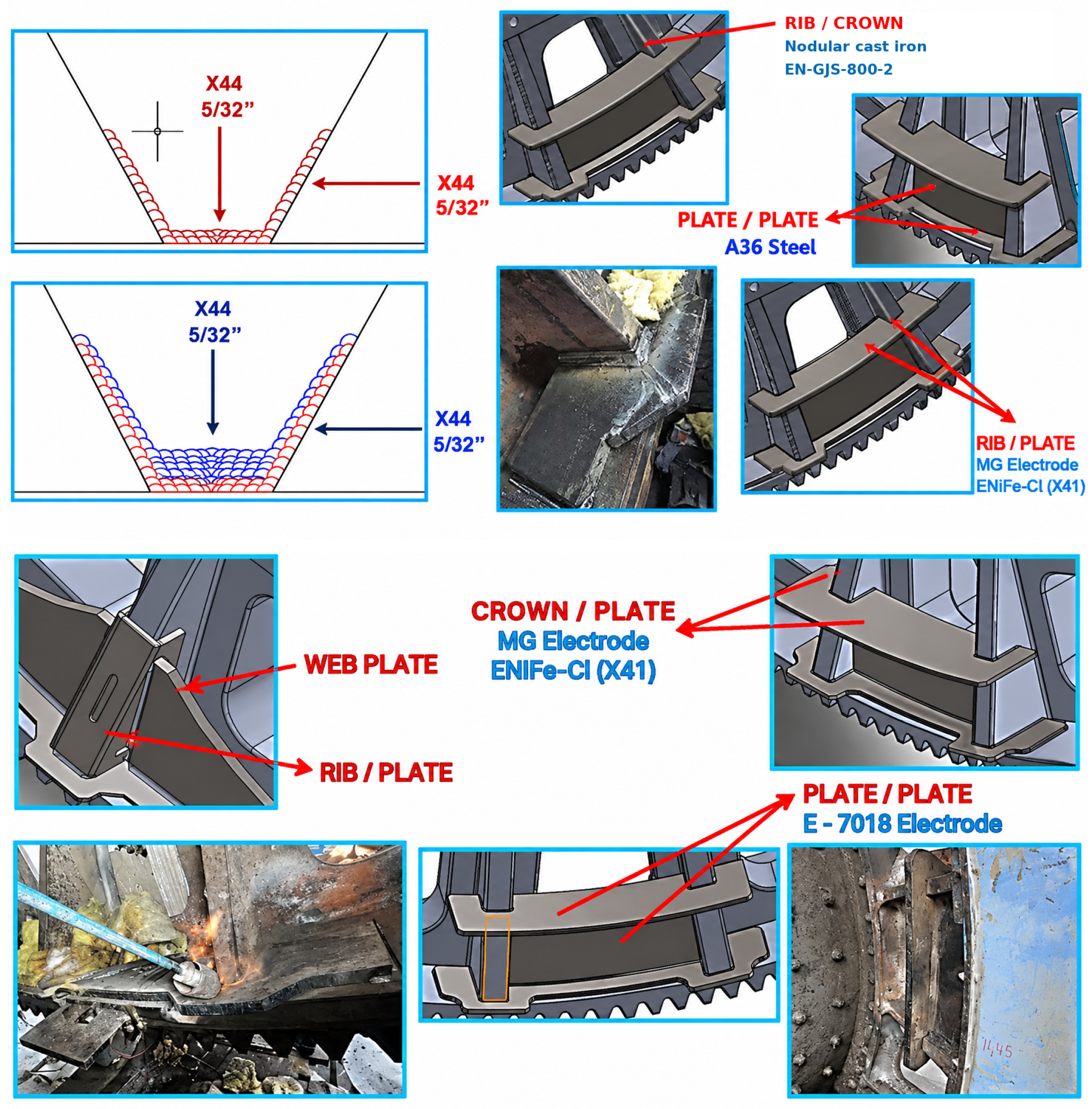
WPS 5 (AGA, optimized hybrid procedure): Applied in October 2025, consolidating the distortion-control approach of WPS 3 with the metallurgical sequence of WPS 4. Parameters: DC 22–28 V, 110–120 A (5/32 in); V-bevel at 60–70°, root opening and root face of 0 to 5/32 in; maximum bead length 50 mm. Operating sequence: (1) rigid environmental sealing and consumable moisture control in portable ovens at 150 °C; (2) homogeneous preheating of the nodular-iron mass (150–200 °C) with light preheating of the A36 Tables (75–100 °C); (3) buttering of the bevel walls with AGA X44 (∼95% Ni) to serve as a carbon migration barrier at the nodular iron interface; (4) dissimilar-joint fill welding with AGA X41 (∼54% Ni/45% Fe); (5) stiffening welds between tabs and A36 plates with E7018; (6) immediate interpass peening, wire brush cleaning, and continuous pyrometric monitoring; (7) encapsulated slow cooling (Figure 11). Following this intervention, the ring gear remained in continuous service without further incident until the original spare part was installed in January 2026.
Figure 11.
Base and filler metal application in WPS 5.
2.6. Resources and Equipment
Table 2 summarizes the principal industrial equipment mobilized for the field repair.
Table 2.
Equipment and consumables used across the five welding procedures.
2.7. Geometric and Vibration Assessment
Post-weld geometric condition was assessed by dial indicator survey of radial run-out at 24 circumferential measurement points, referenced against the nominal theoretical gear profile. Operational vibration was monitored as broadband/global RMS velocity (mm/s) at the main bearing housings. ISO 20816-3:2022 is cited only as contextual guidance for broadband vibration evaluation; no formal ISO zone classification is assigned because the required machine/support information and axis-specific archived channels were not available (see Section 5) [15].
2.8. Operational Mitigation Strategy
When post-weld run-out under WPS 2 produced vibration levels incompatible with continued full-load operation, the ball charge filling degree (%J) and cement throughput (t/h) were progressively reduced in a controlled sequence to keep the mill in a range considered operationally manageable. The RMS vibration was recorded at each step, while the definitive repair (WPS 3–5) and the replacement gear procurement proceeded in parallel.
3. Results
3.1. Initial Failure Condition
The combined VT/PT/UT survey confirmed a 750 mm through-crack at tooth 197 together with secondary cracking (up to ∼50 mm depth) at teeth 19, 20, 24, 120, and 139 (Figure 3). Excavation of the primary crack root revealed porosity, which was reported to the original manufacturer; however, no formal metallurgical report or documented causal hypothesis was made available to the authors.
3.2. Comparative Performance of WPS 1–WPS 5
Table 1 summarizes the outcome of each procedure. WPS 1, applied with a 150–200 °C preheat window and no supplementary restraint, developed transverse post-weld cracks crossing or immediately adjacent to the deposited repair. By contrast, the WPS 3 and WPS 4 indications were localized secondary cracks at reinforcement/interface regions, including the steel plate HAZ. The field evidence distinguishes these crack populations by orientation and location; however, because no direct metallography or residual stress measurements were available, it does not establish that they share the same metallurgical mechanism. WPS 2 substantially reduced the cold cracking indications recorded after WPS 1 by raising preheat to 550–600 °C, but introduced a new dominant failure mode: as the elevated-temperature mass cooled under the rigid ASTM A36 strongbacks, shrinkage forces exceeded the yield strength of the restraint elements, producing localized circumferential flattening of up to −2.8 mm (Section 3.4). WPS 3 addressed this by replacing rigid external restraint with an internal 10 mm root land acting as a mechanical stop against transverse shrinkage, combined with dissimilar ASTM A36 reinforcement using differentiated preheat (150–200 °C cast iron/75–100 °C steel); while this stabilized the joint geometrically, localized secondary cracking was subsequently observed near the reinforcement/interface region. The available evidence does not permit a unique attribution to fatigue, hydrogen-assisted cracking, or shrinkage stress. WPS 4 introduced a differentiated multilayer consumable scheme (pure Ni barrier at the tooth, Ni–Fe at dissimilar interfaces, E7018 for plate-to-plate welds) together with a 300 °C/10 min low-temperature stress relief hold and controlled slow cooling, which was intended to reduce residual stress and delayed-cracking susceptibility; however, a secondary crack again appeared, localized in the plate HAZ. WPS 5, combining the WPS 3 geometric restraint concept with the WPS 4 metallurgical sequence, produced no reported surface-breaking crack indications on PT re-inspection and preserved gear concentricity within the tolerance achieved after the WPS 3–4 corrections.
3.3. Thermal and Geometric Response
The progression from WPS 1 to WPS 2 illustrates a direct trade-off between metallurgy and geometry: raising preheat from 150–200 °C to 550–600 °C substantially reduced the cracking indications observed after WPS 1, a response consistent with lower susceptibility to brittle HAZ transformation under slower cooling conditions. However, the resulting increase in the thermally affected volume in combination with rigid mechanical restraint produced shrinkage forces that exceeded the elastic capacity of the strongback elements. This is consistent with the physical expectation from the linear thermal expansion relationship : a larger over a large and massive sector generates proportionally larger contraction forces which a rigid external restraint can only accommodate up to its own yield limit. When WPS 3 replaced the external rigid restraint with an internal mechanical root land, subsequent procedures (WPS 4, WPS 5) no longer produced measurable circumferential flattening.
3.4. Run-Out and Mechanical Consequences
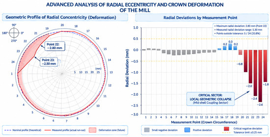
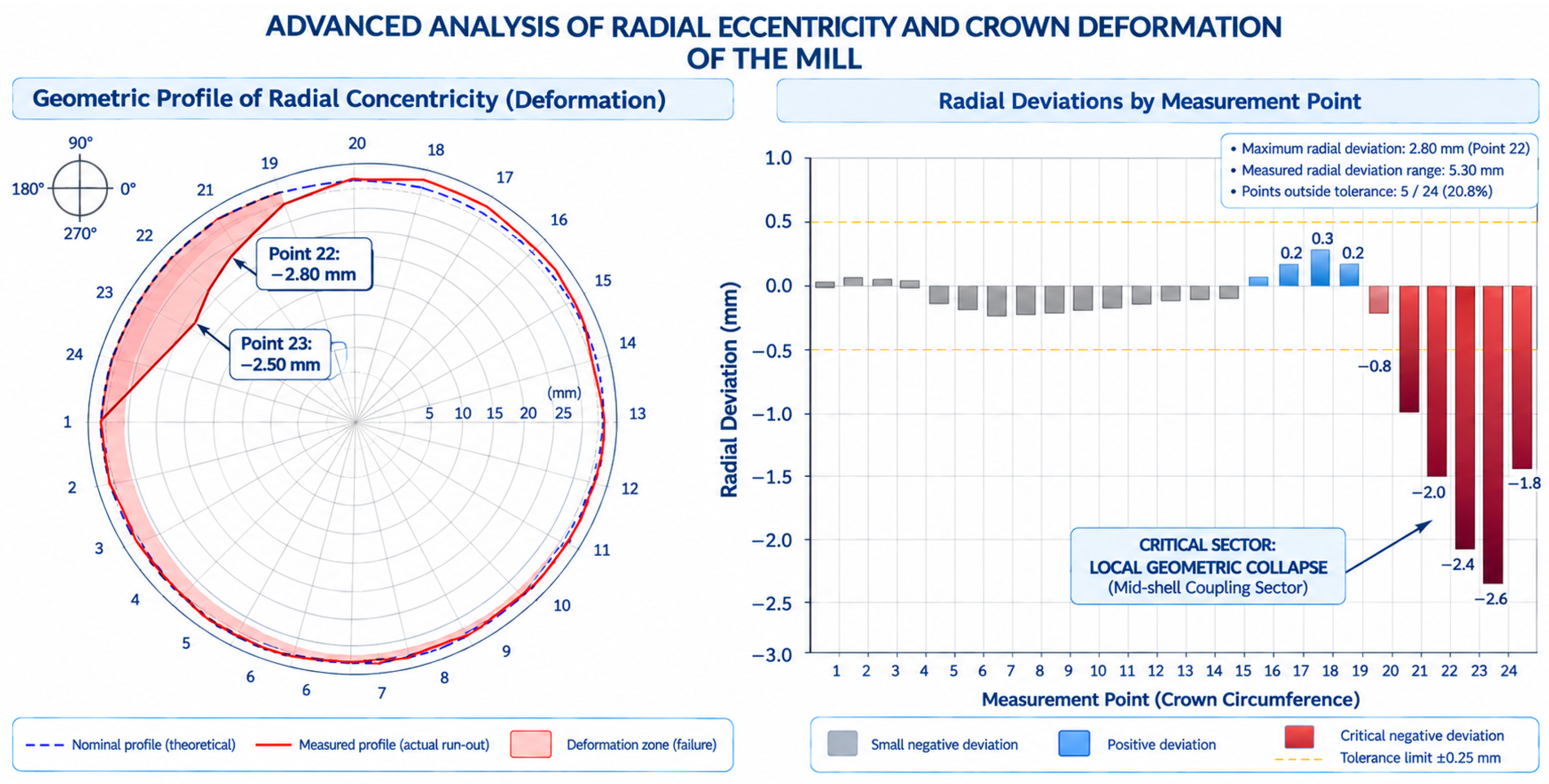
The post-weld dial indicator survey after WPS 2 identified the most severe deviations between teeth 20 and 24, with a peak of −2.8 mm at point 22 and −2.5 mm at point 23 (Figure 12); five of the 24 measurement points (∼21%) exceeded the ±0.25 mm reference tolerance indicated on the field dimensional report. This radial deviation collapsed gear backlash in the affected sector, causing the pinion to strike the deformed tooth flanks intermittently during mesh engagement.
Figure 12.
Post-weld (WPS 2) radial run-out: polar concentricity profile (left) and per-point radial deviation (right), showing the localized −2.8 mm/−2.5 mm deformation between measurement points 20 and 24. Source: plant preventive maintenance department.
3.5. Vibration Response
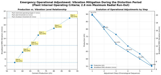
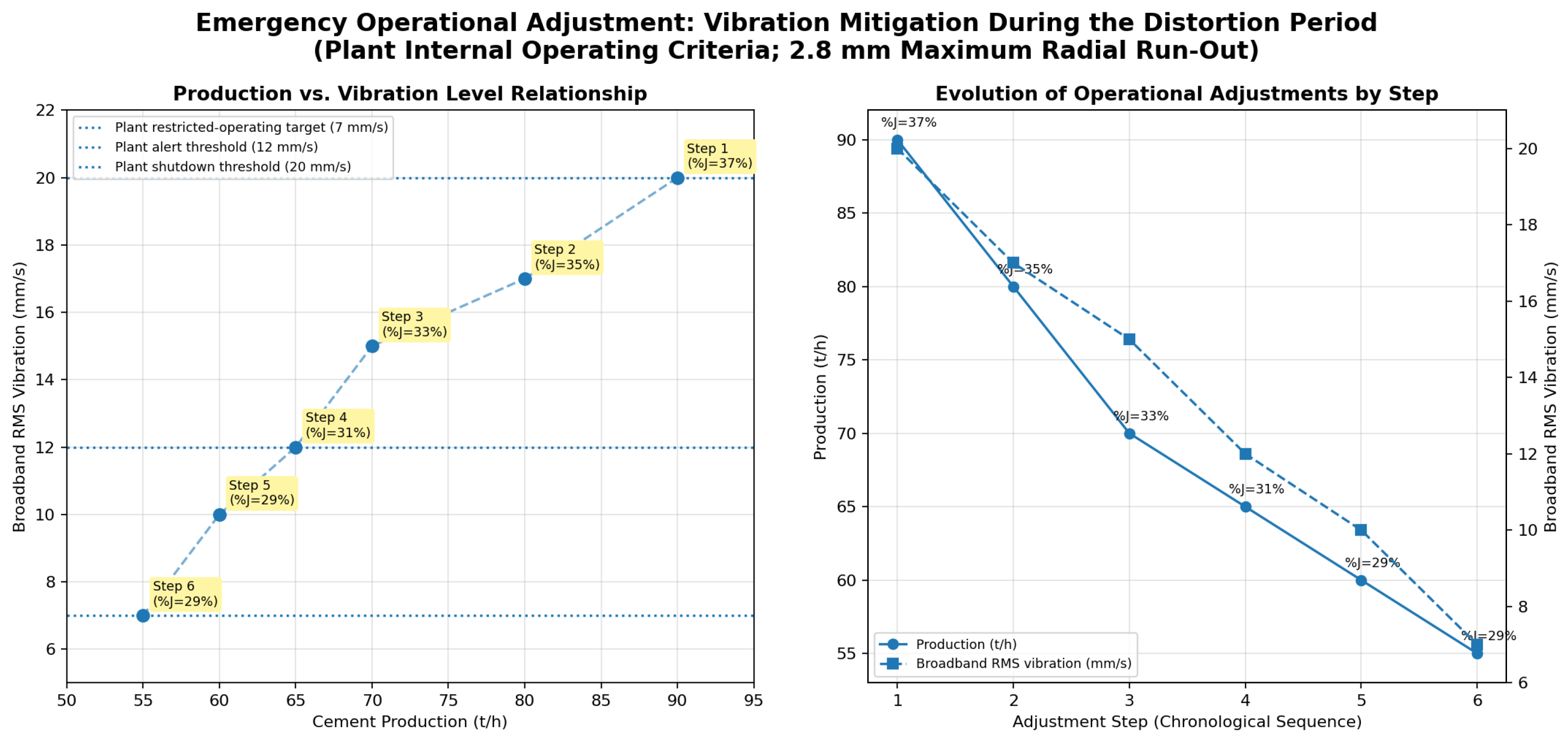
The intermittent pinion–tooth impact associated with the WPS 2 run-out coincided with an increase in broadband RMS vibration velocity measured at the main bearing housings to approximately 20 mm/s, a level the field team classified as requiring immediate action. The surviving field records report a global broadband RMS value but do not preserve the axis-specific horizontal, vertical, or axial channels; therefore, the reported values must be interpreted as plant-recorded global RMS indicators rather than direction-specific measurements. To keep the mill in service while the definitive geometric repair was completed, ball charge filling degree and cement throughput were reduced stepwise, with vibration recorded at each step (Table 3, Figure 13). Reducing the feed from 90 to 55 t/h and the ball filling from 37% to 29% reduced RMS vibration from 20 mm/s to 7 mm/s. The field interpretation is that the reduced rotating mass lowered the frictional resistant torque at the tooth flanks, while accumulated cement material at the bottom of the drum acted as a passive viscous damping cushion that absorbed part of the impact energy generated as the tooth passed through the −2.8 mm eccentric sector. While this mechanism is offered as a plausible explanation consistent with the observed correlation between the operational variables in this study, it has not been independently verified by dedicated modal or impact force measurements.
Table 3.
Sequential adjustment of operational variables during the distortion mitigation period.
Figure 13.
Interrelation of ball charge filling degree, production rate, and plant-recorded global broadband RMS vibration during operational de-escalation. The 7 and 20 mm/s values are internal plant operating criteria, not formal ISO 20816-3 zone boundaries. Source: plant preventive maintenance department.
3.6. Operational Mitigation
The controlled reduction of ball charge and throughput summarized in Table 3 allowed the plant to remain in operation at reduced capacity throughout the period required to complete WPS 3–WPS 5 and procure the original replacement gear, thereby avoiding a full production stoppage.
3.7. Final Industrial Validation
Following WPS 5 (October 2025), the repaired ring gear operated continuously without further incident until the original replacement part arrived and was installed in January 2026, at which point operational variables returned to nominal values (90 t/h, 37% ball filling, 3.0–4.0 mm/s vibration). Commercial or warranty outcomes are intentionally excluded from the engineering interpretation because they do not constitute evidence of failure causation.
4. Discussion
The five-procedure development sequence documented here illustrates a trade-off that is difficult to observe at coupon scale but becomes operationally decisive at the scale of a multi-tonne girth gear: metallurgical measures that suppress HAZ embrittlement in EN-GJS-800-2 (principally, elevated preheat) increase the thermally affected volume, and consequently the magnitude of shrinkage-driven distortion, while measures that limit distortion (rigid external restraint) can be overwhelmed if the restraint stiffness is mismatched to the shrinkage forces involved, leading to failure in a different purely geometric mode. The WPS 1→WPS 2 transition is consistent with this reading: the comparatively low preheat (150–200 °C) of WPS 1 is compatible with published evidence that insufficiently controlled cooling rates in nodular iron promote martensitic transformation and cold cracking in the HAZ [8,9]; while the elevated preheat (550–600 °C) of WPS 2 is consistent with the metallurgical rationale for high preheat in heavy-section cast-iron welding, its outcome shows that rigid mechanical restraint is not by itself an adequate distortion control strategy once thermal input and restrained mass reach this scale.
The transition from WPS 2 to WPS 3–5—replacing external rigid restraint with an internal mechanical root land—is consistent with the general principle documented for repair welding of high-restraint steel structures that transverse shrinkage is better controlled by joint geometry design than by opposing it with stiffness alone [14]. A quantitative restraint stiffness was not measured in the field. Qualitatively, the WPS 2 strongbacks were external A36 members with thickness of 1.5 inches, spanning the joint and opposing contraction after a 550–600 °C preheat. Their restraint depended on the strongback geometry and attachment welds, and was accompanied by localized circumferential flattening. In WPS 3–5, the 10 mm integral root land remained part of the joint cross-section and provided local geometric continuity directly at the root while still allowing the surrounding massive gear body to redistribute contraction. The comparison is qualitative and based on geometry and observed outcome rather than a measured stiffness ratio. The interpass peening and controlled interpass temperature protocol common to all five procedures is consistent with established practice for mitigation of residual stress in restrained multi-pass welds [11,13], and the low-temperature post-weld stress relief/controlled cooling treatment introduced in WPS 4 (300 °C, slow cooling under insulation) is consistent with the role reported in the literature for controlled post-weld cooling in preventing delayed hydrogen cracking in high-restraint joints [11,13].
In the procedure terminology used here, “buttering” denotes the initial thin ENi-CI layer deposited directly on prepared cast-iron surfaces before structural fill; subsequent groove filling/reconstruction used the designated ENiFe-CI or ENi-CI layers according to the interface shown in Figure 9 and Figure 10. The selection of nickel and nickel–iron consumables (ENi-CI for buttering, ENiFe-CI for the dissimilar interface) followed the same rationale reported by other authors for cast-iron repair welding: nickel’s negligible carbon solubility limits carbide formation at the fusion boundary, while its ductility accommodates the strain mismatch between the brittle base iron and the weld deposit [10,11,12]. The persistence of localized secondary cracking under WPS 3 and WPS 4 despite an apparently sound metallurgical scheme is consistent with residual restraint stress concentrated at the steel plate HAZ rather than with a filler metal deficiency. This interpretation is offered as the most probable explanation given the available field evidence; however, as no dedicated residual stress measurement was performed in this study, it has not been independently confirmed.
The link between welding-induced run-out and mill vibration observed here (Section 3.4 and Section 3.5) is consistent with the general expectation documented for large rotating gear transmissions that geometric deviation in a gear mesh translates directly into cyclic impact loading and elevated vibration amplitude [1,2,3,4,5,20,21]. The operational mitigation strategy applied here, consisting of reducing the ball charge and throughput to lower rotating mass and impact energy, has not to our knowledge been previously documented in the open literature as a temporary vibration management response to welding-induced girth gear distortion, and represents a practical operational contribution of this case independent of its underlying dynamic explanation.
ISO 20816-3:2022 is used in this paper only as contextual guidance for the concept of broadband vibration evaluation, and is not used to assign a formal acceptance zone to the 17 rpm ring gear. The standard’s evaluation framework depends on machine group, support/foundation classification, and applicable measurement conditions, none of which were fully documented in the surviving field records for this mill. The 7 mm/s restricted operating target and the 20 mm/s shutdown threshold are internal plant operating criteria obtained from the maintenance records, and as such are measured as broadband/global RMS indicators as opposed to ISO 20816-3 limits. The unusually low rotational speed warrants further caution when transferring generic velocity severity criteria to the gear itself.
Positioning Against Related Repair Welding and Gear Failure Studies
Table 4 positions the present work against representative studies that address the closest individual elements of the problem. Prior studies of ductile iron welding provide strong metallurgical, hardness, mechanical property, or fracture mechanics evidence at coupon or plate scale [8,10,11,12,13]; recent work has also quantified the effect of repair welding residual stresses on fatigue behavior in a full-scale ductile iron component [22]. By contrast, gear failure studies provide detailed root cause analysis of failed ring gears, but do not develop and validate an iterative repair procedure under continued process operation [1,2]. The distinguishing contribution of the present study is the integration, in one field case, of five sequential WPS iterations with NDT, dimensional run-out, vibration response, operational derating, and a final in-service validation period. This broader systems-level evidence complements rather than replaces the direct microstructural and fracture mechanics characterization available in controlled studies.
Table 4.
Comparison with representative literature on ductile cast-iron repair welding and gear failure.
5. Limitations
This study reports a single industrial repair case, and the five WPS were developed sequentially in the field rather than as a designed and replicated experimental comparison; consequently, the relative contribution of each individual process variable (preheat, filler chemistry, joint geometry, restraint) to the outcome of each procedure cannot be isolated with statistical confidence. No direct metallographic, microhardness, scanning electron microscopy (SEM), or residual stress characterization was performed on the welded joints. Removal of a representative coupon from the operating ring gear was not permitted because it would have further reduced the load-bearing section of a component that had to remain serviceable. Consequently, the HAZ phase transformation, carbide/martensite, carbon migration, and residual stress explanations in the above Discussion section are materials science interpretations supported by published studies rather than microstructurally confirmed observations from this gear. The vibration severity thresholds used operationally by the plant are reported as provided in the field records. The formal ISO 20816-3:2022 machine/support/foundation classification required to assign a normative vibration zone boundary was not documented and is not established in this study; additionally, the archived records do not preserve axis-specific vibration channels, so only the reported global broadband RMS values can be analyzed. Field operating conditions (uncontrolled ambient temperature, personnel rotation, non-laboratory instrumentation) introduce variability not present in controlled experimental studies. The follow-up period for the final procedure (WPS 5) was bounded by the arrival of the replacement gear (approximately three months of continuous service before decommissioning), which, while operationally meaningful, is shorter than a full multi-year fatigue life assessment would require. Despite these limitations, the principal value of this work lies precisely in the fact that it documents field-scale evidence, under real industrial constraints, of variables and interactions that are difficult to reproduce experimentally at this component scale.
6. Conclusions
An industrially validated field-developed emergency repair framework is reported for a cracked EN-GJS-800-2 nodular cast-iron ball mill ring gear, integrating iterative welding procedure development, thermal and distortion control, dissimilar material reinforcement, and vibration-based operational monitoring. The main findings are as follows:
- Across five sequential SMAW procedures, the lower-preheat WPS 1 condition (150–200 °C) was associated with transverse post-weld cracking, while elevated preheat combined with rigid external mechanical restraint (WPS 2, 550–600 °C) substantially reduced the cracking indications observed after WPS 1 but produced severe localized distortion, up to −2.8 mm radial run-out.
- Replacing rigid external restraint with an internal 10 mm mechanical root land (WPS 3 onward) in combination with a differentiated nickel buttering/nickel–iron-dissimilar/controlled cooling metallurgical scheme (WPS 4–5) progressively improved distortion control and reduced post-weld cracking indications; the final hybrid procedure (WPS 5) showed no surface-breaking crack indications on the reported PT re-inspection and preserved the corrected gear concentricity.
- The −2.8 mm run-out observed after WPS 2 coincided with main-bearing broadband RMS vibration of approximately 20 mm/s; a controlled stepwise reduction of the ball charge filling degree (37%→29%) and production rate (90→55 t/h) reduced RMS vibration to approximately 7 mm/s, allowing continued restricted operation while the definitive repair and gear replacement were completed.
- Following WPS 5, the repaired gear operated continuously for approximately three months (October 2025–January 2026) until the original replacement part was installed, avoiding a multi-month full production stoppage that a 9–18-month original-equipment lead time would otherwise have required.
- These results support the technical feasibility of SMAW-based dissimilar repair of EN-GJS-800-2 nodular iron—a material generally regarded as having poor weldability owing to its pearlitic matrix and propensity for hard and brittle transformation products under rapid cooling—when preheat, joint geometry, filler metal chemistry, and restraint strategy are co-designed rather than treated as independent variables.
- The phase transformations and HAZ mechanisms discussed in this paper are literature-supported interpretations; direct microstructural sampling of the working gear was not feasible. Future work should include dedicated microstructural and residual stress characterization of the welded joints, a formal machine-specific vibration assessment appropriate to the low-speed mill, including the information required to determine whether and how ISO 20816-3:2022 should be applied, and where feasible, replication of the WPS 5 procedure on additional girth gear repairs to build a broader evidence base beyond this single case, complemented by a systematic assessment of the relationship between repaired-gear geometry, mesh excitation, and vibration under controlled operating conditions [1,2].
Author Contributions
Conceptualization, S.Á.C.B., M.D.A.A., and J.E.N.; methodology, S.Á.C.B., I.O.G.B., O.V.S.I., and J.C.P.M.; validation, S.Á.C.B., M.D.A.A., I.O.G.B., and J.C.P.M.; formal analysis, M.D.A.A., O.V.S.I., and J.E.N.; investigation, S.Á.C.B., I.O.G.B., O.V.S.I., and J.C.P.M.; resources, S.Á.C.B. and J.C.P.M.; data curation, I.O.G.B., O.V.S.I., and M.D.A.A.; writing—original draft preparation, S.Á.C.B., M.D.A.A., and J.E.N.; writing—review and editing, all authors; visualization, M.D.A.A. and J.E.N.; supervision, S.Á.C.B. and J.E.N.; project administration, S.Á.C.B. All authors have read and agreed to the published version of the manuscript.
Funding
This research received no external funding.
Institutional Review Board Statement
Not applicable. The study did not involve human or animal subjects.
Informed Consent Statement
Not applicable.
Data Availability Statement
The data presented in this study are available on request from the corresponding author. The data are not publicly available due to confidentiality restrictions associated with the industrial company involved in this study.
Acknowledgments
The authors gratefully acknowledge Universidad Técnica de Cotopaxi (UTC) for its institutional support during the development of this research.
Conflicts of Interest
The authors declare no conflicts of interest.
Abbreviations
The following abbreviations are used in this manuscript:
| SMAW | Shielded Metal Arc Welding |
| WPS | Welding Procedure Specification |
| HAZ | Heat-Affected Zone |
| NDT | Non-Destructive Testing |
| VT | Visual Testing |
| PT | (Liquid) Penetrant Testing |
| UT | Ultrasonic Testing |
| PWHT | Post-Weld Heat Treatment |
| HIC | Hydrogen-Induced (cold) Cracking |
| RMS | Root Mean Square |
| ISO | International Organization for Standardization |
| AWS | American Welding Society |
References
- Li, F.; Ding, N.; Song, M.; Zhong, Z.; Liu, L.; Shen, X.; Xu, H.; Tian, L.; Xu, N.; Guo, W.; et al. A Review on Research of Gear Failures in Mechanical Equipment. J. Fail. Anal. Prev. 2025, 25, 612–648. [Google Scholar] [CrossRef] [Scilit]
- Fantin, L.d.B.; Moreira, M.F.; Moreira, A.R. Failure analysis of a tandem mill ring gear. Eng. Fail. Anal. 2023, 151, 107391. [Google Scholar] [CrossRef] [Scilit]
- Fernández-del Rincón, A.; Iglesias, M.; de Juan, A.; Diez-Ibarbia, A.; García, P.; Viadero, F. Gear transmission dynamics: Effects of index and run out errors. Appl. Acoust. 2016, 108, 63–83. [Google Scholar] [CrossRef] [Scilit]
- Pei, Y.C.; Xie, H.L.; Tan, Q.C. A non-contact high precision measuring method for the radial runout of cylindrical gear tooth profile. Mech. Syst. Signal Process. 2020, 138, 106543. [Google Scholar] [CrossRef] [Scilit]
- Saracoglu, G.; Yapici, A. Fatigue analysis of girth gear of a rotary dryer. Eng. Fail. Anal. 2016, 68, 187–196. [Google Scholar] [CrossRef] [Scilit]
- Crespo Márquez, A.; De la Fuente, A.; Gómez Fernández, J.F. Smart Maintenance Management in Industry 4.0: Frameworks, Technologies, and Applications; Springer: Berlin/Heidelberg, Germany, 2022. [Google Scholar] [CrossRef]
- Collini, L.; Nicoletto, G. Microstructure and mechanical properties of nodular graphite cast irons. Mater. Sci. Eng. A 2022, 832, 142435. [Google Scholar] [CrossRef] [Scilit]
- Trubitz, P.; Grützner, S.; Krüger, L. Contribution to the Fracture Mechanics Characterization of Repair Welding of Thick-Walled Ductile Cast Iron Components. Int. J. Met. 2025, 19, 1634–1649. [Google Scholar] [CrossRef] [Scilit]
- Benedetti, M.; Torresani, E.; Fontanari, V.; Lusuardi, D. Fatigue and Fracture Resistance of Heavy-Section Ferritic Ductile Cast Iron. Metals 2017, 7, 88. [Google Scholar] [CrossRef] [Scilit]
- El-Banna, E.M.; Nageda, M.S.; Abo El-Saadat, M.M. Study of restoration by welding of pearlitic ductile cast iron. Mater. Lett. 2000, 42, 311–320. [Google Scholar] [CrossRef] [Scilit]
- Gouveia, R.M.; Silva, F.J.G.; Paiva, O.C.; Andrade, M.F.; Silva, L.; Moselli, P.C.; Papis, K.J.M. Study of the Heat-Treatments Effect on High Strength Ductile Cast Iron Welded Joints. Metals 2017, 7, 382. [Google Scholar] [CrossRef] [Scilit]
- Martinez Alcon, J.; Pascual Guillamon, M.; Solano Garcia, L.; Salas Vicente, F. Mechanical and microstructural analysis in the welding of ductile cast iron by TIG procedure, with different filler materials and air cooling. Rev. De Metal. 2021, 57, e194. [Google Scholar] [CrossRef] [Scilit]
- El-Banna, E.M. Effect of preheat on welding of ductile cast iron. Mater. Lett. 1999, 41, 20–26. [Google Scholar] [CrossRef] [Scilit]
- Kendall, O.; Paradowska, A.; Abrahams, R.; Reid, M.; Qiu, C.; Mutton, P.; Yan, W. Residual Stress Measurement Techniques for Metal Joints, Metallic Coatings and Components in the Railway Industry: A Review. Materials 2023, 16, 232. [Google Scholar] [CrossRef] [Scilit] [PubMed]
- ISO 20816-3:2022; Mechanical Vibration—Measurement and Evaluation of Machine Vibration—Part 3: Industrial Machinery with a Power Rating Above 15 kW and Operating Speeds Between 120 r/min and 30 000 r/min. ISO: Geneva, Switzerland, 2022.
- American Welding Society. Specification for Welding Electrodes and Rods for Cast Iron; Technical Report AWS A5.15/A5.15M:2021; American Welding Society: Doral, FL, USA, 2021. [Google Scholar]
- AGA. Messer and Sager. Fichas Técnicas de Electrodos y Procedimientos de Soldadura para Reparación de la Corona del Molino de Bolas CM4. Technical Report, Internal Technical Documentation. 2024; unpublished internal technical document.
- Foster, J.; Smallcombe, J.W.; Hodder, S.; Jay, O.; Flouris, A.D.; Nybo, L.; Havenith, G. An advanced empirical model for predicting the physiological strain caused by workplace heat exposure. Eur. J. Appl. Physiol. 2021, 121, 2915–2929. [Google Scholar] [CrossRef]
- Rowlinson, S.; Yunyan, J.; Yantao, Y. Heat stress management in heavy industrial operations: Human factors and occupational health protocols. Saf. Sci. 2022, 152, 105780. [Google Scholar] [CrossRef]
- Luo, Y.; Xu, L.; Hu, R.; Zhou, F. A novel contact dynamics modeling method for profile-shifted spur gear pairs considering geometric eccentricity. J. Sound Vib. 2026, 620, 119453. [Google Scholar] [CrossRef] [Scilit]
- Lu, W.; Liang, G.; Du, Z.; Huang, W.; Zhao, X. Dynamic coupling effects of geometric eccentricity on multi-stage gear transmission via stiffness modulation and error excitation. Sci. Rep. 2026, 16, 3707. [Google Scholar] [CrossRef] [Scilit] [PubMed]
- Shakeri, I.; Borzabadi Farahani, E.; Sobhaniaragh, B.; Eder, M.A.; Darvishi Kamachali, R.; Sarhadi, A. Effect of repair welding-induced residual stresses on fatigue crack growth and life of ductile cast iron: Application to a full-scale wind turbine hub. Eng. Fail. Anal. 2026, 193, 110891. [Google Scholar] [CrossRef] [Scilit]

Disclaimer/Publisher’s Note: The statements, opinions and data contained in all publications are solely those of the individual author(s) and contributor(s) and not of MDPI and/or the editor(s). MDPI and/or the editor(s) disclaim responsibility for any injury to people or property resulting from any ideas, methods, instructions or products referred to in the content. |
© 2026 by the authors. Licensee MDPI, Basel, Switzerland. This article is an open access article distributed under the terms and conditions of the Creative Commons Attribution (CC BY) license.