


Abstract
The article is aimed at studying the features of the hot rolling mill CWBRM-1700 of JSC “Qarmet”, which negatively affect the operation of the distribution network of the workshop. Such factors are frequent shock loads of technological mechanisms with high installed capacity of the equipment. Experimental studies of the distribution network of the rolling production on the buses of the 10 kV substation showed that shock loads of synchronous electric drives of roughing stands lead to periodic voltage drops of up to 13% lasting 5–6 s. Mathematical modeling in the MATLAB/Simscape/Electrical environment, the results of which coincide with the data of the experimental study, showed that the most significant factor affecting the quality of electricity are abrupt changes in the reactive power of the synchronous motor from −0.5 to +0.5 MVAR. To solve the problem, it is proposed to use a controlled filter-compensating device. Variants of circuit solutions for such devices are considered. The choice was made in favor of a three-phase adjustable LLC filter with diode–transistor keys. The article develops a method for calculating the electromagnetic parameters of such a filter and establishes that in order to reduce the level of harmonic distortion of voltage, it is necessary to use a triangle connection of the controlled reactive compensator and select the PWM frequency of the transistors, a multiple of the tripled frequency of the power grid. Two options for creating a closed-loop control system for energy modes are studied: a reactive power stabilization system and a voltage stabilization system in a distribution network node, which reduce the duration of transient processes to 0.5 s and reduce the voltage drop in the network node to −4 to + 1% in the first case and to −4 to + 3% in the second, also reducing reactive power consumption to 0.02 MVAR and 0.25 MVAR, respectively. The advantage of a closed-loop control system with voltage stabilization is the ability to use a technically less complex voltage sensor.
1. Introduction
Rolling production is one of the most complex technological processes, since it closely intertwines the physical and chemical processes of metal deformation, the operation of complex technological mechanisms of mills and the functioning of their electric drives. Rolling production is one of the most energy-intensive types of industrial production, and the installed capacity of power transformers of the shop power supply system in some cases can reach 100 MVA. The impact of powerful technological mechanisms on the shop power supply system, in particular due to significant fluctuations in reactive power, leads to voltage drops in the power grid.
Improving the accuracy of hot rolling mill flying shears directly affects economic indicators: reducing the output of process waste (cuttings) and the share of substandard slabs rejected due to non-compliance with length tolerances due to minimizing deviations from the specified size. Elimination of distortions and impact loads during cutting due to increased accuracy of knife positioning increases the period between repairs and the service life of critical equipment components (cylinders, cutting edges, frames), which reduces maintenance and spare parts costs and reduces the risk of unscheduled downtime.
Therefore, increasing the stability and efficiency of electrical equipment of metallurgical units, issues of reactive power compensation and the need to ensure electromagnetic compatibility remain relevant tasks for this class of technological processes.
The aim of the study is to investigate the operating features of the CWBRM-1700 hot rolling mill (Novokramatorsky Mashinostroitelny Zavod (NKMZ), Kramatorsk, Ukraine) of JSC “Qarmet” mill and to develop an active filter with a closed-loop control system that compensates for periodic fluctuations in reactive power and the associated significant voltage drops in the electrical network, which will improve the quality of the mill’s products and reduce equipment downtime both in roughing stands and in parallel technological processes.
This study for the first time develops a calculation method for the electromagnetic parameters of a controlled reactor compensator ensuring linear reactive power regulation and tests dual control modes: reactive power and voltage stabilization.
The article comprises the following main sections: Introduction, providing the rationale for the study; A Review of Modern Literature, analyzing existing methods of reactive power compensation and power quality improvement; Case Study and Methods, describing the power supply system of the CWBRM-1700 hot rolling mill, operated at JSC “Qarmet” in Temirtau, Kazakhstan, the experimental study of voltage quality, the mathematical model developed in MATLAB R2024a/Simscape/Electrical (The MathWorks, Inc., Natick, MA, USA), and the design and control principles of the controlled reactor compensator; Results and Discussion, presenting the effectiveness of the proposed open-loop and closed-loop control systems in reducing voltage drops and reactive power fluctuations; and Conclusions, summarizing the main findings and outlining directions for further research.
2. A Review of Modern Literature
In modern power distribution systems, industrial consumers not only consume active power, but also create significant reactive power flows, which is accompanied by significant voltage fluctuations. The widespread use of semiconductor converters also leads to harmonic distortions of voltage and current, affecting the overall performance and reliability of the power system.
To solve these problems and improve the quality of electricity, active power filters (APFs) have been developed and improved for many years, the selection of which requires both technical and economic analysis depending on the specific operating conditions [1].
Active–passive hybrid filters for minimizing the level of harmonics in three-phase electrical systems make it possible to achieve compliance with the IEEE-519 standard, reducing the level of harmonic distortion by 59% [2], without affecting the reactive power flows. Various methods are used to synthesize active filter control systems. Thus, the ANN–Grasshopper optimization for an asynchronous electric drive provides a significant reduction in current and voltage harmonics, which leads to increased motor performance and energy efficiency. However, the obtained results cannot be used for other types of powerful consumers [3]. In [4], a neural network algorithm based on ADALINE is used to estimate the parameters of a three-phase load, which allows controlling the APF to maintain sinusoidal source currents and unity power factor (PF). The beam matrix method (MPM) [5] for more accurate extraction of the reference voltage allows achieving a significant reduction in harmonic voltage distortion. To improve APF control for dynamic and nonlinear loads, a neural network is used in combination with the theory of instantaneous reactive power [6] and signal preprocessing using a modified symmetric sinusoidal integrator (MSSI) [7]. In [8,9], two main control strategies are compared: a sliding mode (BSMC, TSMC) and a neuro-fuzzy controller based on ANFIS and a modified wavelet fuzzy neural network (MWFNN).
In [10], the authors use an adaptive neuro-fuzzy inference system based on a generalized bell-shaped membership function. In [11], a model of predictive control (MPC) is applied and the effectiveness of MPC and its compliance with regulatory requirements are confirmed. In [12], a combined method for reducing harmonics in the system under various load disturbances is presented using a fractional-order proportional integral differential controller optimized using a chicken flock optimization algorithm. The authors of [13,14] consider power quality problems caused by nonlinear and asymmetric loads, as well as reverse energy flow from renewable sources, which lead to harmonic distortions and reactive power. An optimized PI controller and an optimized output filter are proposed to improve the quality of the supplied current.
In [15], the impact of nonlinear loads on power quality is described, with a special emphasis on rectifiers as a key source of such problems. For complex parallel RC loads connected to rectifiers, the authors propose an improved shunt active filter operating on the double fundamental component extraction scheme using a reduced-order generalized integrator and the addition of a choke.
Based on these requirements, it is necessary to select a rational scheme of an active compensating device, to justify the possibility of ensuring the necessary values of power quality indicators during the functioning of a rolling mill.
To achieve this goal, it is necessary to solve the following scientific and practical problems:
- Analyze typical features of the operation of distribution electric power networks, taking into account the characteristics of rolling production; identify priority problems in the operation of these networks;
- Analyze the general principles of designing controlled compensating devices; select a rational design of a compensating device for the distribution power grid of a rolling mill;
- Develop a method for calculating the electromagnetic parameters of a reactor compensating device;
- Develop a mathematical model of a closed control system for a compensating device; justify the achievement of the required indicators of electric power quality in the distribution electric power network of a rolling production facility.
3. Case Study and Methods
3.1. Structure of the Workshop Power Supply System of the Rolling Production
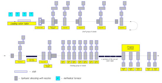
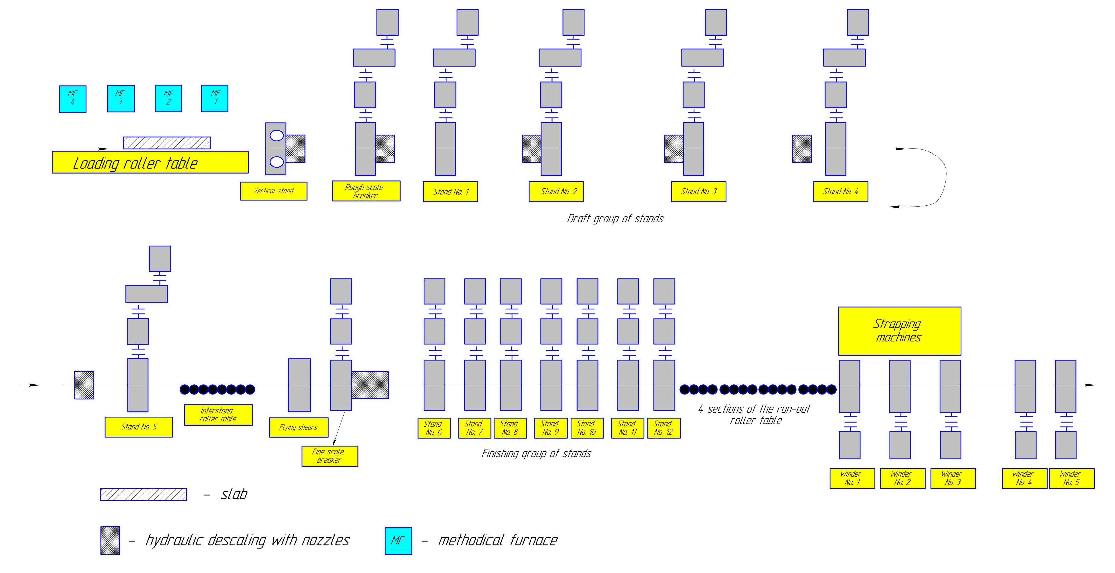
The object of research is hot rolling mill CWBRM-1700 of JSC “Qarmet” (Temirtau, Kazakhstan), which is a complex multi-connected electromechanical system with five roughing and seven finishing stands, as well as several cutting units and a spar strip unit, which ensure high productivity and compliance with modern requirements for metal quality. Figure 1 shows the layout of the technological equipment of sheet rolling shop No. 1 of JSC “Qarmet”.
Figure 1.
Layout of technological equipment of sheet rolling shop No. 1 of JSC “Qarmet”, Temirtau city.
The working rolls of the roughing group stands are driven by a synchronous AC electric motor with a capacity of up to 4600 kW, ensuring the stability of the preliminary rolling process. The electric drive of the working rolls in the finishing group is carried out by DC motors with independent excitation: for stand No. 6, a motor with a capacity of 3150 kW is used, and for stands No. 7–No. 12, motors with a capacity of 3600 kW are used.
The main source of impact loads in the power supply system of the rolling mill CWBRM-1700 of JSC “Qarmet” are powerful unregulated synchronous motors of the stands of the roughing group. Impact loads occur when the slab enters the rolls.
Another source of impact loads are drum shears equipped with a thyristor dual-motor DC electric drive with a total power of 3500 kW. Impact loads occur when cutting the front and rear ends of the rolled product [16,17].
Previous studies have shown that the start-up of high-power electric drives can be coordinated by an optimal control law that minimizes energy consumption and limits dynamic stresses, which is particularly relevant for impact-loaded rolling mill mechanisms [18].
Fault-tolerant optimal control of high-voltage frequency converters with damaged power cells also demonstrates the possibility of maintaining acceptable drive performance under converter faults, thereby increasing the continuity and reliability of metallurgical production [19].
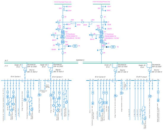
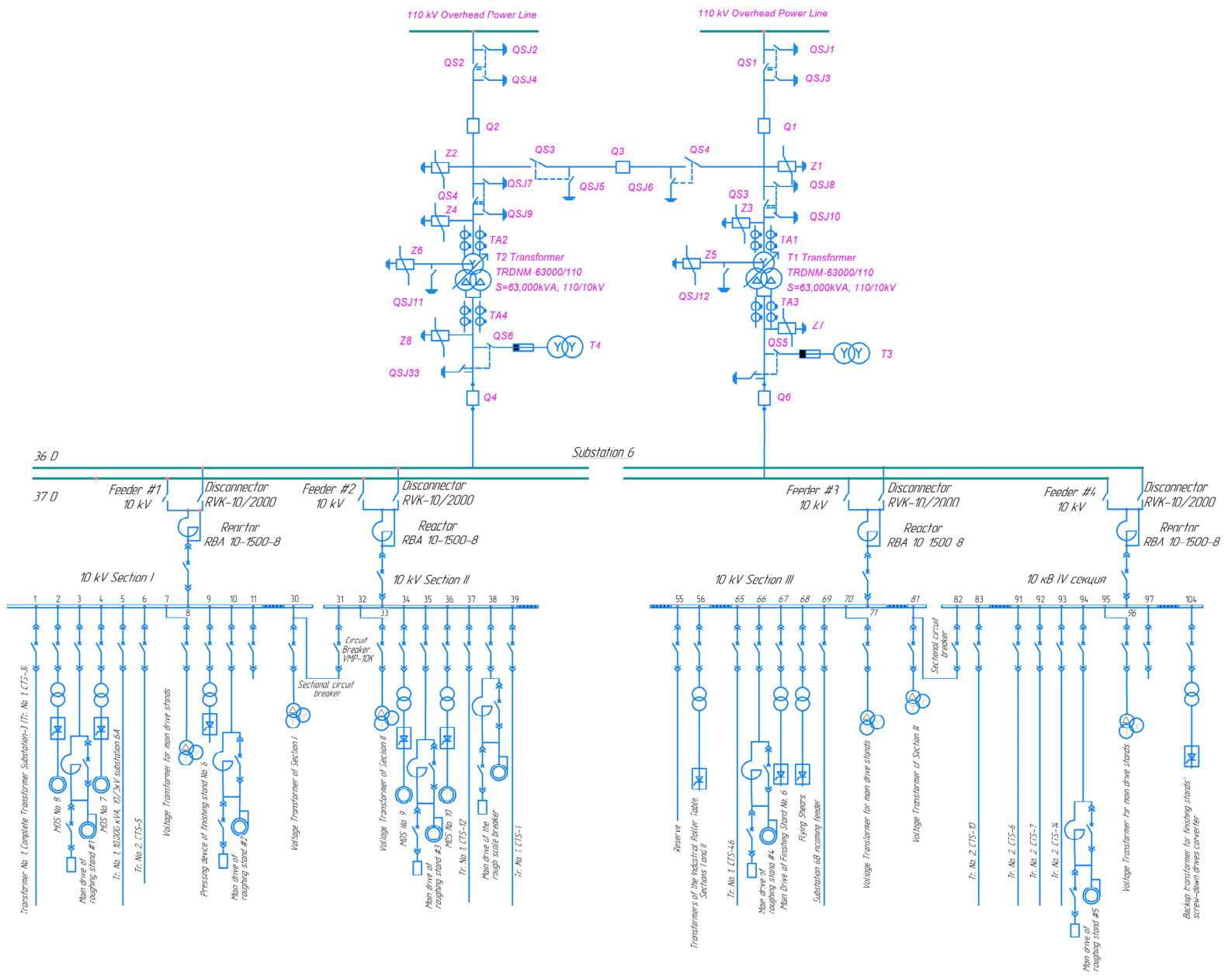
For the rolling mill CWBRM-1700 of JSC “Qarmet”, the power supply for hot rolling production is carried out from the power system at a voltage of 110 kV according to the diagram shown in Figure 2.
Figure 2.
Power supply diagram of the CWBRM-1700 mill of JSC “Qarmet”.
The power supply of the CWBRM-1700 mill of JSC “Qarmet” is carried out through substation No. 6 (10 kV) from the two-transformer main step-down substation MSS-1A (110/10 kV).
The secondary windings of 10 kV dynamically stable transformers of the TRDNM-63000/110/10 type (Zaporozhtransformator, Zaporizhzhia, Ukraine) form a two-section distribution device, from which four 10 kV sections of substation No. 6 are supplied, providing power to the equipment of the hot rolling mill CWBRM-1700 of JSC “Qarmet”.
This configuration ensures reliable energy distribution across all process units of the rolling mill, maintaining voltage stability even under variable load conditions. The interconnected structure of the substation sections allows for flexible power management and redundancy in case of equipment failure or maintenance. Such an arrangement is crucial for continuous metallurgical production, where even short-term voltage drops or interruptions can lead to significant process disruptions and product quality deterioration.
Substations supplying power to auxiliary mechanisms of the mill and a number of other process areas are also connected to the 10 kV MSS buses.
3.2. Experimental Study of the Voltage Quality in the Power Supply Network of the Hot Rolling Mill CWBRM-1700 of JSC “Qarmet”
The operation of synchronous electric drives of the roughing group of the rolling mill is accompanied by significant shock loads at the moment of entry of the slab into the rolls. With the existing configuration of the power supply system, these shock loads lead to significant voltage drops on the buses of one of the transformers of the two-transformer substation.
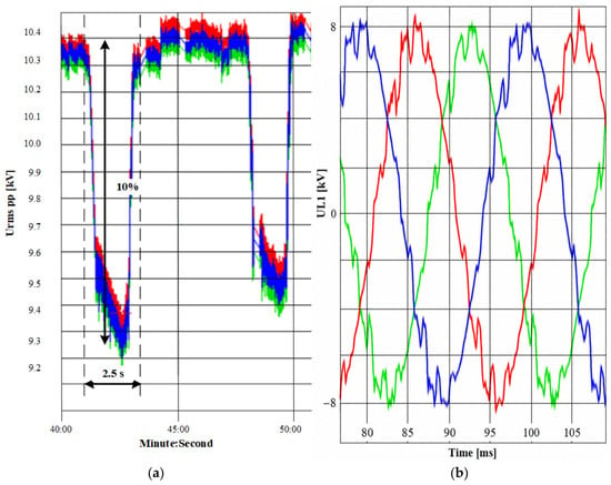
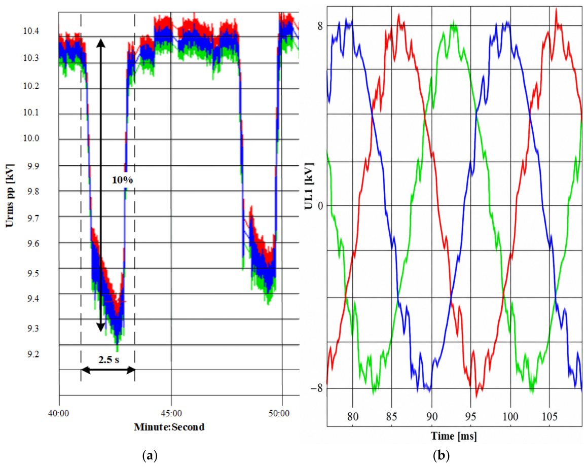
Figure 3 shows the results of an experimental study of the voltage quality during metal rolling on the buses of substation No. 6 (10 kV). The graphs were obtained using the RESURS-UF2M-3T52-5-100-1000 electric energy quality meter (NPP Energotechnika, Penza, Russia), certified in accordance with the standards of the Republic of Kazakhstan and, in particular, when measuring voltage, characterized by an error of no more than 0.1% of the nominal voltage [20].
Figure 3.
Experimental study of voltage quality in the power supply system of the CWBRM-1700 mill of JSC “Qarmet”: (a) voltage drops in the 10 kV network during rolling; (b) the shape of the voltage curve of the 10 kV network during rolling. The colored curves represent the three-phase voltage waveforms.
At the moment the metal enters the rolls, a sharp load application occurs, causing a decrease in voltage. At the same time, the registerogram clearly shows the impact surge and subsequent load drop. Analysis of the registerogram shows that throughout the rolling process, voltage dips are recorded, reaching up to 12% of the nominal value and lasting up to 2.5 s.
3.3. General Principles of Application of Controlled Compensating Devices in the Structure of Workshop Power Supply Systems
As the main means of ensuring electromagnetic compatibility of shop power supply networks with power semiconductor converters, relatively simple filter-compensating devices based on passive inductive-capacitive filters are widely used, which ensure both an improvement in the shape of the current and voltage of the network and compensation of reactive power. Improved methods for calculating electromagnetic processes and indicators of the quality of electricity in shop power supply networks with power semiconductor converters and filter-compensating devices were developed in [21,22]. The main disadvantage of the most common passive filter-compensating devices with fixed element parameters is their lack of controllability, which leads, with a wide range of regulation of the loads of power semiconductor converters, to the emergence of modes of both undercompensation of reactive power and its overcompensation [21,22]. This circumstance necessitates an overestimation of the installed capacity of generators and leads to a decrease in the efficiency and technical and economic indicators of shop power supply networks as a whole. The above-mentioned negative factors are eliminated by using controlled filter-compensating devices, which provide additional advantages: reduction in active power losses and reduction in network voltage fluctuations.
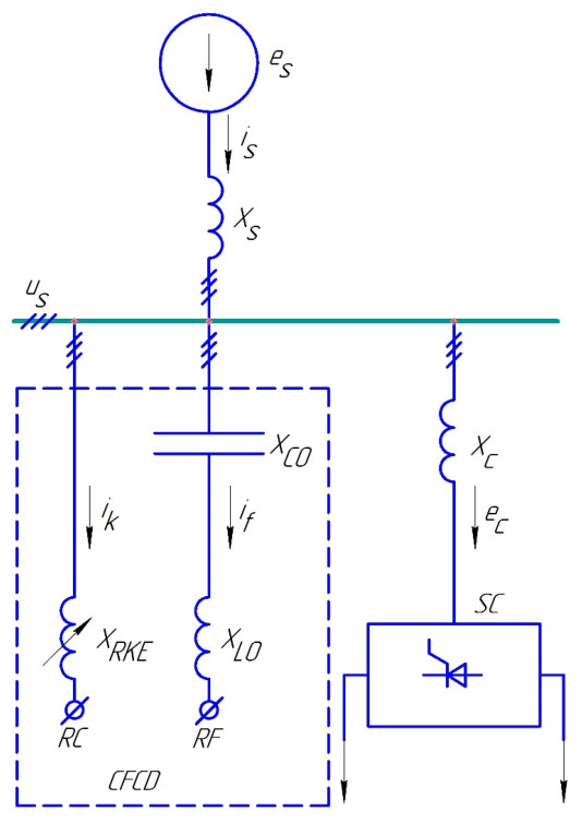
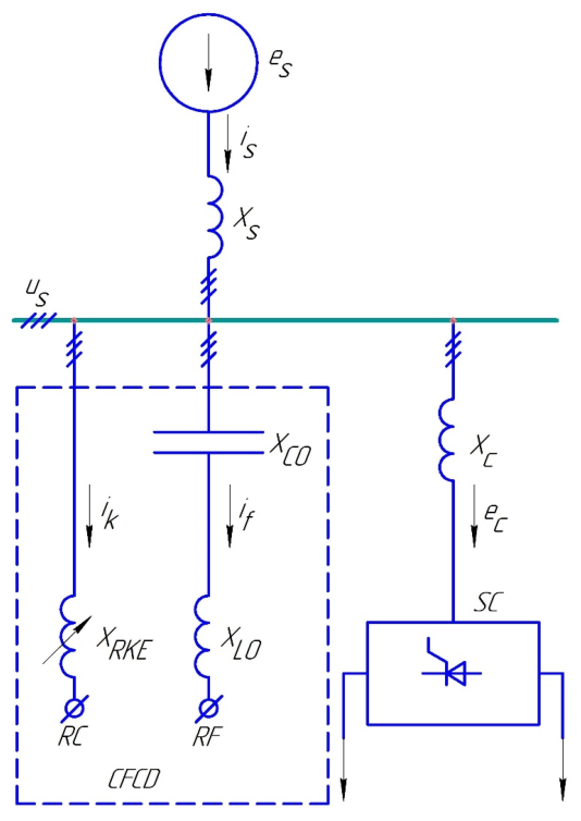
The generalized diagram of the shop power supply network with a semiconductor converter and a controlled filter-compensating device is shown in Figure 4. The generator (power supply network) is represented by a source of sinusoidal EMF with an amplitude and a short-circuit resistance and the transformer or input reactor of the semiconductor converter by a resistance . The controlled filter-compensating device includes a resonant longitudinal —filter, which consists of resistances and a reactor compensator, conventionally designated by an adjustable equivalent resistance at the fundamental harmonic . The order of the tuning frequency of the resonant filter corresponds to zero of the frequency responses of the system and is selected from the condition:
where
Figure 4.
Single-line structural diagram of a workshop power supply network with a semiconductor converter and a controlled filter-compensating device. The dashed box indicates the controlled filter-compensating device (CFCD), and the arrows indicate the reference directions of the corresponding currents.
is the resonant frequency of the filter;
is the circular frequency of the network;
is the pulse rate of the semiconductor converter.
When reducing higher harmonics, the resonant filter is simultaneously a generator of reactive power at the fundamental harmonic.
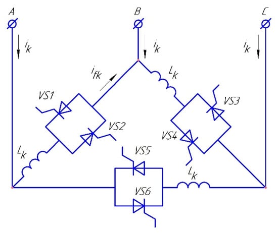
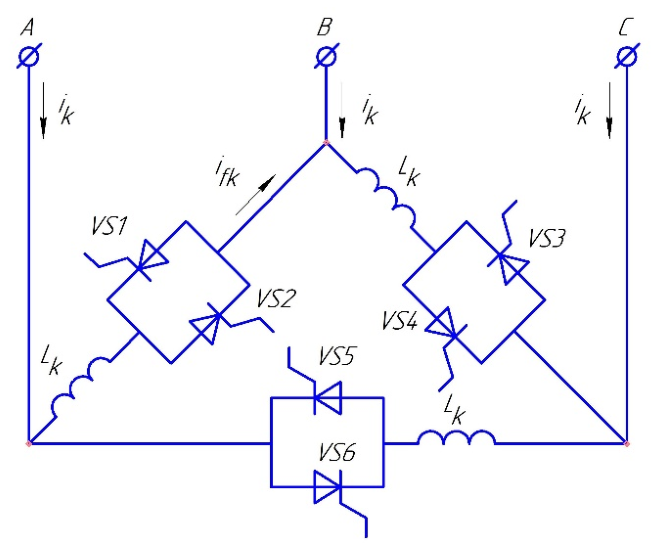
In practice, the most widely used —circuit is one based on reactors with inductance connected in series with anti-parallel connected single-operation thyristors with phase control (Figure 5) [23].
Figure 5.
Reactor compensator with thyristor keys.
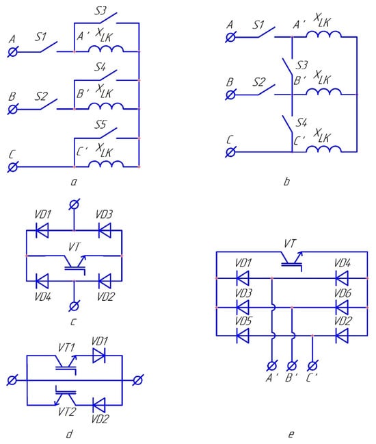
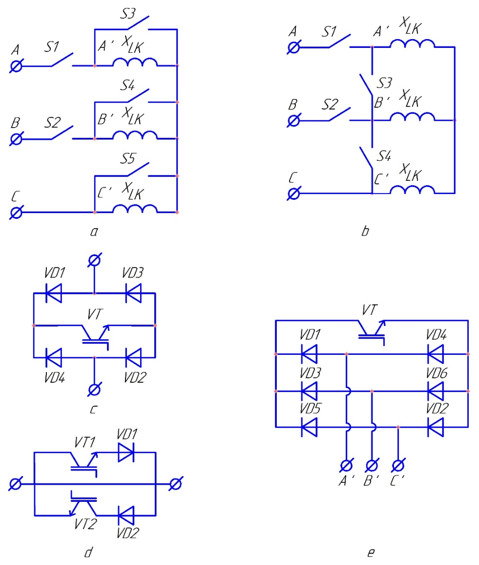
Three-phase reactor compensators with semiconductor pulse width regulators based on AC switches, shown in Figure 6a,b [21,24], can also be used.
Figure 6.
Three-phase reactor compensator with semiconductor pulse width regulation: (a,b) main structures of the reactor compensator; (c,d) semiconductor AC switches; (e) short-circuiter on one semiconductor DC switch.
The main disadvantages of the reactor compensator (Figure 5) are the generation of low-frequency harmonics of the current in the power supply network, as well as a significant control delay time, which is half the period.
From those presented in Figure 6, due to the connectivity property of three-phase networks without a neutral wire, a simplification is achieved in comparison with the direct combination of single-phase regulators. For example, in the circuits in Figure 6a,b, five and four keys are used, respectively, instead of six. Semiconductor AC keys, made on the basis of transistors and diodes are shown in Figure 6c,d. Instead of transistors, two-operational thyristors can be used. The version of the key in Figure 6c, is preferable, since it contains a smaller number of controlled elements.
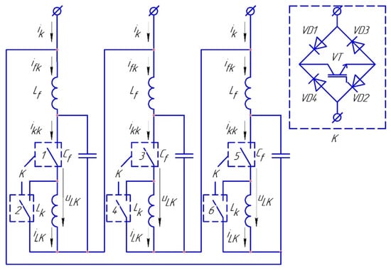
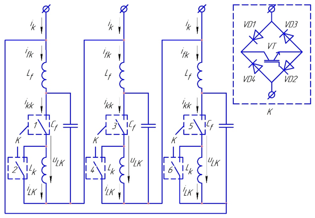
The best control characteristics are possessed by a fast-acting reactor compensator with pulse width regulation at high frequency (Figure 7) [21,23,24,25,26].
Figure 7.
Schematic diagram of a three-phase active power filter.
The basis of the circuit consists of three inductive elements and six semiconductor AC switches (1–6), conventionally represented as contacts.
The key elements can be implemented on the basis of a bridge diode–transistor circuit (Figure 6c). Dual-operation thyristors (GTO, IGCT) [27] can be included in the bridge diagonal instead of IGBT transistors. In each phase of such a reactor compensator circuit, there are two keys operating in antiphase: one of them is connected in series, and the other is parallel to .
Since the dynamic behavior of semiconductor converters is sensitive to resonant circuit and load parameters, their possible variation should be taken into account when selecting the switching frequency, semiconductor devices, and electromagnetic parameters of the compensator [28].
3.4. Calculation Method of Electromagnetic Parameters of a Controlled Reactor Compensator
The calculation of the electromagnetic parameters of the controlled reactor compensator is carried out on the basis of information about the maximum and minimum values of the compensated reactive power as follows:
Each branch of the controlled filter shown in Figure 7 is in one of two states at any given time. These states correspond to the filter’s reactive resistances :
where are the modules of the reactive resistances of the filter elements.
Obviously, can be both negative and positive depending on the ratio of parameters. Based on the ratio:
we determine the boundary values of the filter’s reactive resistance and calculate the parameters, for example, in the following sequence:
We set the value of the capacitor and find:
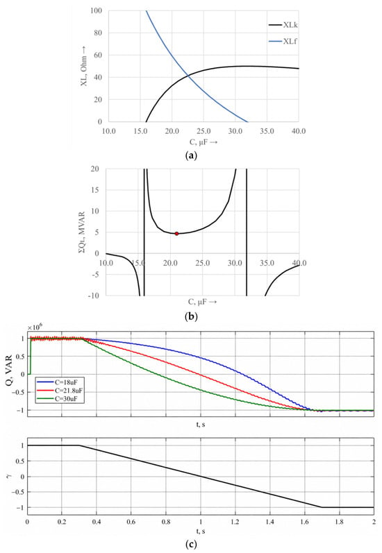
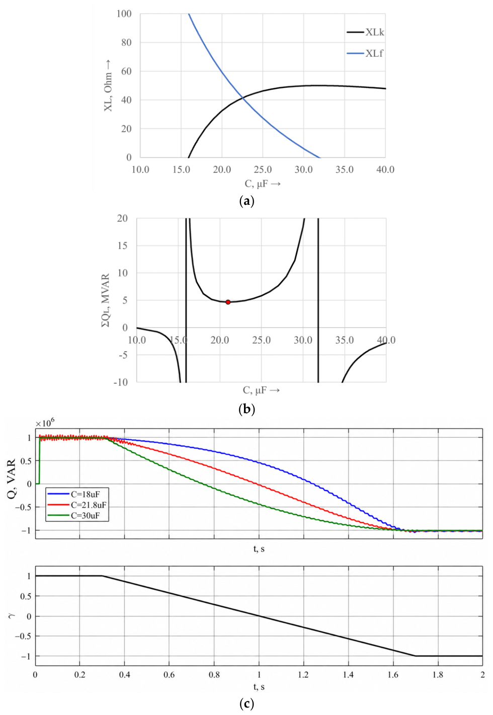
It should be noted that with such a sequence of parameter selection, the inductive resistances take positive values only in a limited range of capacity (Figure 8a) and only if compensation of the greatest positive reactive power is specified in the main operating mode . Then the filter in this state must have the greatest reactive power of a capacitive nature :
Figure 8.
Dependences of the inductive resistance of the filter (a); the total reactive power of the coils (b) on the capacity; and the control characteristics of the filter (c). The red dot in (b) indicates the local minimum of the total reactive power of the coils corresponding to .
Next, to set the filter parameters by power, we define:
For example, for a high-voltage filter with U = 10 kV, f = 50 Hz the calculated electromagnetic parameters of the controlled reactor compensating device are summarized in Table 1. These parameters were determined based on the maximum and minimum values of the compensated reactive power and characterize the reactive resistances of the main filter elements under different switching states of the control keys.
Table 1.
Electromagnetic parameters of the reactor compensating device.
In addition, there is a value at which :
Also, the total reactive power of the coils in this same range has a local minimum at some , close to (Figure 8b). It is important that at and the corresponding dependence of the filter’s reactive power on the control signal , changing the duty cycle of the key control pulses, is practically linear (Figure 8c), which is essential when synthesizing an automatic reactive power controller.
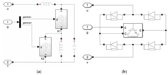
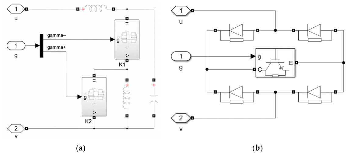
The last graphs were obtained in the model developed in the MATLAB R2024a Simscape Electrical environment [27,29,30,31,32,33]. Figure 9 shows the models of the controlled reactor compensator and the two-operational diode–transistor switch.
Figure 9.
Implementation of the single-phase model of a three-phase reactor compensator (a) and the model of a two-operation diode–transistor switch (b) in MATLAB/Simscape/Electrical.
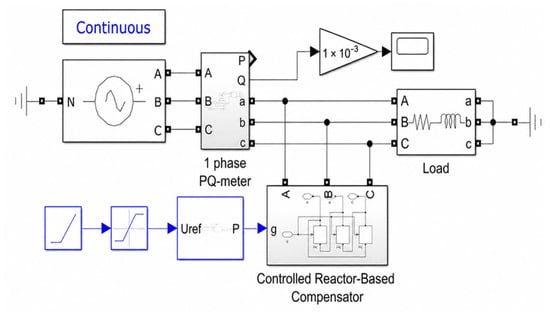
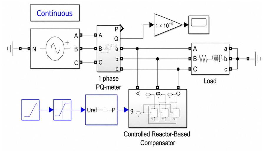
To check the operability of the mathematical model of the controlled three-phase reactor compensator, let us consider the operation of the simplest shop power supply system consisting of a power source U = 10 kV, f = 50 Hz, connected to an equivalent RL load with parameters R = 1 Ohm; L = 5∙× 10−5 H. A controlled three-phase reactor compensator is connected in parallel to the load, as shown in Figure 10. In the proposed model, the switching frequency of the transistor switches is 1350 Hz.
Figure 10.
Model of the simplest workshop power supply system with a controlled three-phase reactor compensator.
The compensator’s control system adjusts the inductive reactance in order to maintain the desired power factor and voltage stability at the load terminals. The simulation makes it possible to evaluate the effectiveness of the compensator in reducing reactive power and improving the quality of electrical energy supplied to the consumer. The obtained results form the basis for further experimental validation and optimization of the control algorithm under real operating conditions.
The combination of mathematical simulation with physical laboratory models is an effective approach for validating automatic control algorithms; this methodology has previously been demonstrated for an optimal control system of a thermal object and for an automatic control system with a fuzzy controller [33,34].
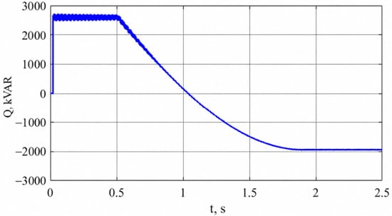
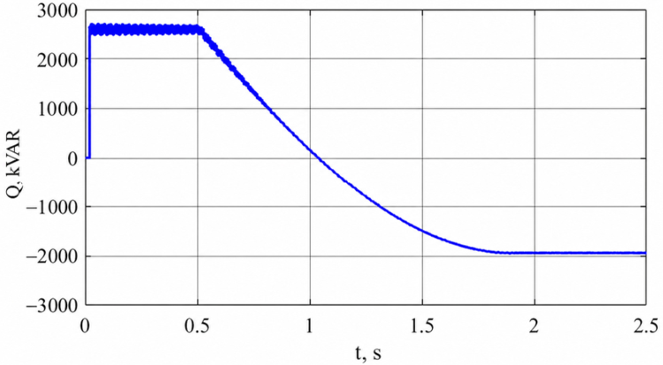
The reactor compensator starts working at the moment of time t = 0.5 s, and then increases the equivalent capacity of the reactor compensator to the maximum value according to the linear law. The operation of the model is controlled by the value of reactive power on the power source buses.
The data obtained as a result of the calculation are presented in Figure 11.
Figure 11.
Dependence of reactive power on the power supply buses when switching on a controlled three-phase reactor compensator.
As the three-phase reactor compensator operates, starting from the moment of its switching on at time t = 0.5 s, the total reactive power decreases uniformly, changing the nature of the load from inductive at the beginning of operation to capacitive when the reactor compensator is fully switched on. This nature of the change in the total reactive power confirms the operability of the proposed circuit solution for the controlled reactor compensator.
3.5. Study of a Controlled Reactor Compensator for Managing Energy Modes of the Power Supply Network of the CWBRM-1700 Mill of JSC “Qarmet”
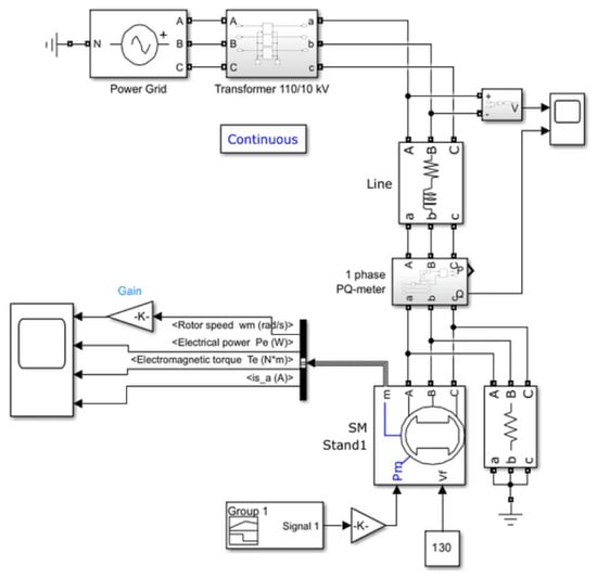
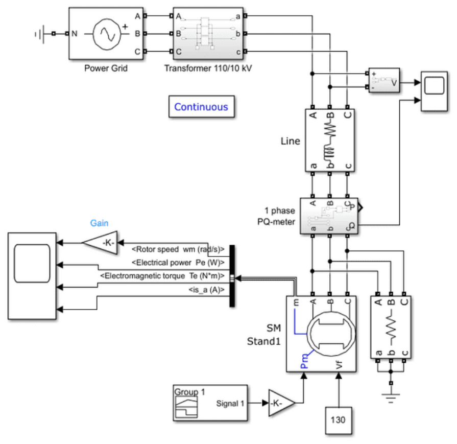
To justify the possibility of using a controlled reactor compensator in real production conditions, a mathematical model of a section of the shop power supply system of the CWBRM-1700 mill of JSC “Qarmet” was developed according to the diagram in Figure 2. Cell No. 1 of the first section was selected as the modeling object, to which the drive synchronous motor of stand No. 1 of the roughing group is connected, the rated power of which is 4200 kW.
The model of the section of the shop power supply system shown in Figure 12 was implemented in MATLAB/Simulink/Simscape Electrical (The MathWorks, Inc., Natick, MA, USA) and includes simulation blocks representing a 110 kV power grid source, a step-down transformer TRDNM-63000/110/10, and a cable line. The model contains a line voltage sensor and a single-phase reactive power meter at the terminals of a synchronous motor.
Figure 12.
Mathematical model of the section of the shop power supply system of the CWBRM-1700 mill of JSC “Qarmet”.
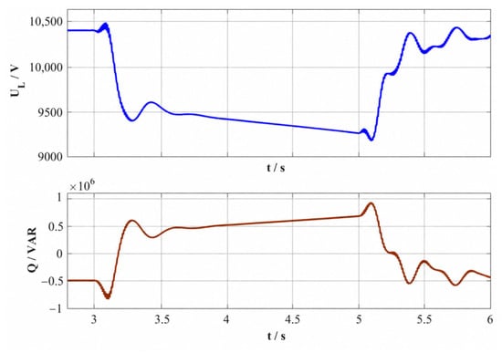
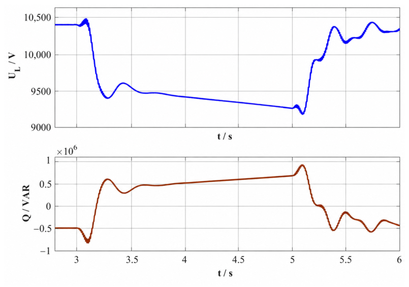
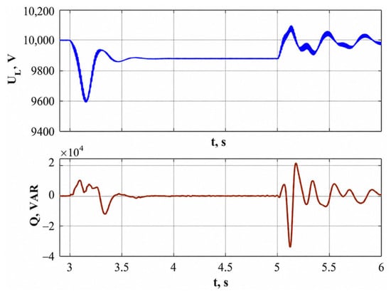
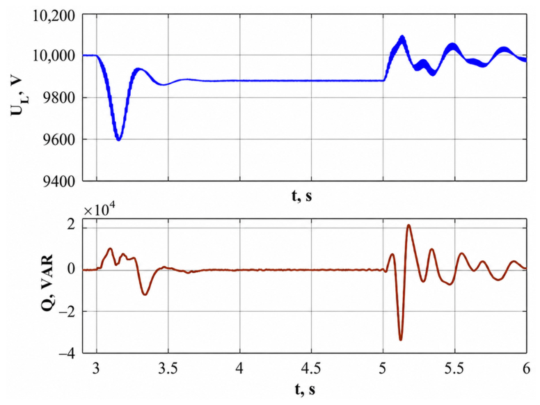
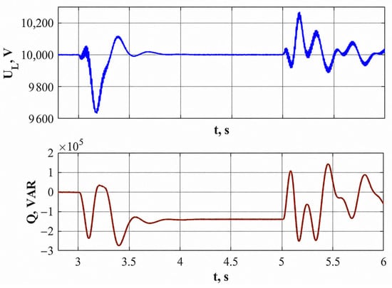
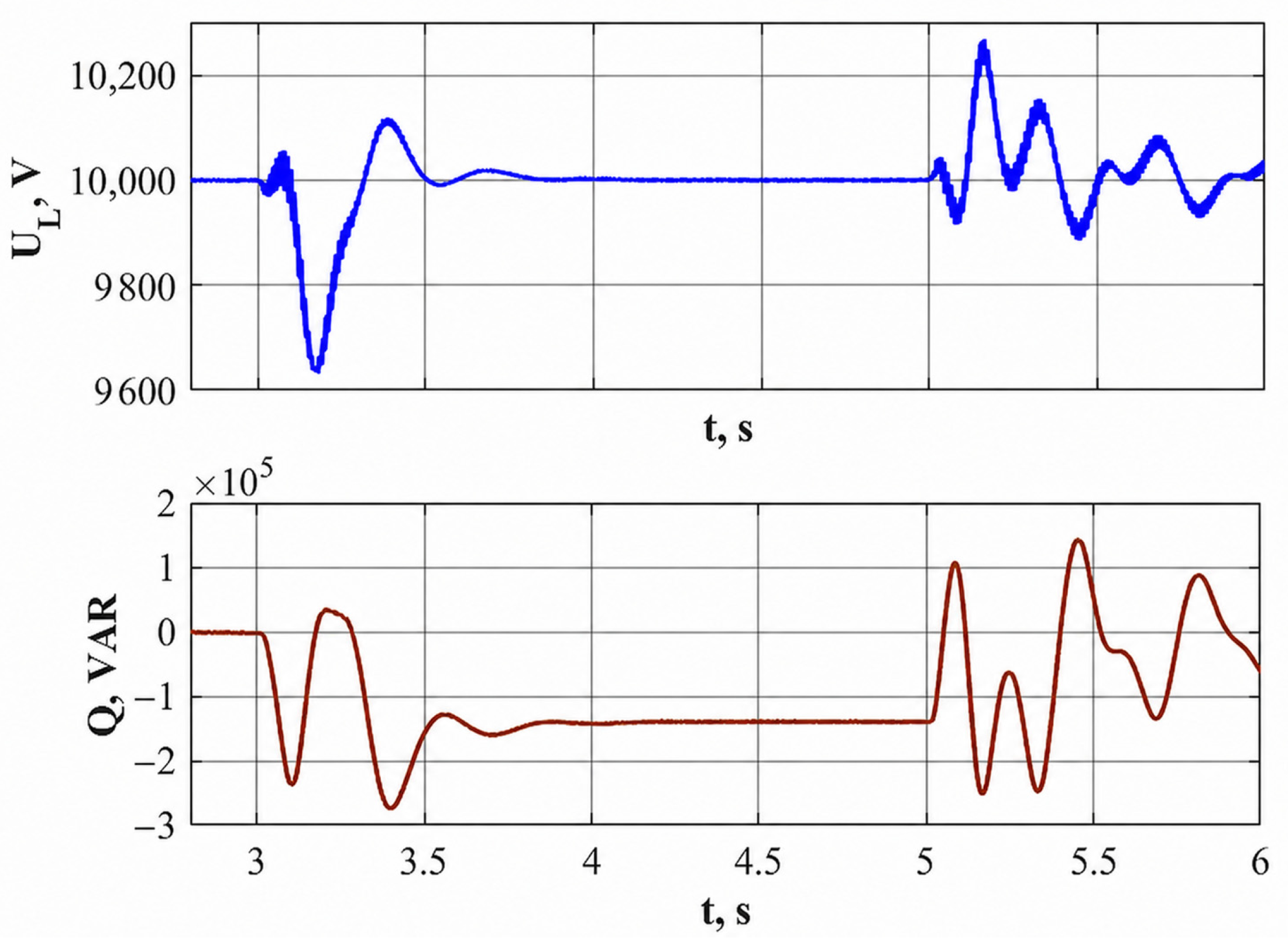
The presented mathematical model is used to calculate transient processes in the power supply system of the CWBRM-1700 mill under the shock loading of the synchronous motor of the roughing stand. The load of the synchronous motor increases significantly when the slab enters the rolls of the roughing stand at time t = 3 s and decreases when the slab exits the rolls at time t = 5 s.
The results of these calculations, including the transient variations in voltage UL and reactive power Q, are shown in Figure 13.
Figure 13.
Calculation of transient processes in the power supply system of the CWBRM-1700 mill under impact load.
As shown by the comparison of the results of calculating the voltage drop in a node of the power supply system with the data of the experimental study, Figure 3a, the numerical data obtained on the mathematical model coincide with the data of the experimental study with high accuracy.
When a shock load is applied to the shaft of a synchronous motor, both the magnitude and sign of the reactive power consumed by the synchronous motor change. This type of change in reactive power is fully consistent with theoretical concepts of the operation of a synchronous motor and its U-shaped characteristic.
To compensate for fluctuations in reactive power and voltage drop in the load node with a synchronous motor, we use a controlled reactor compensator, as shown in Figure 7.
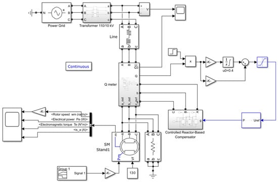
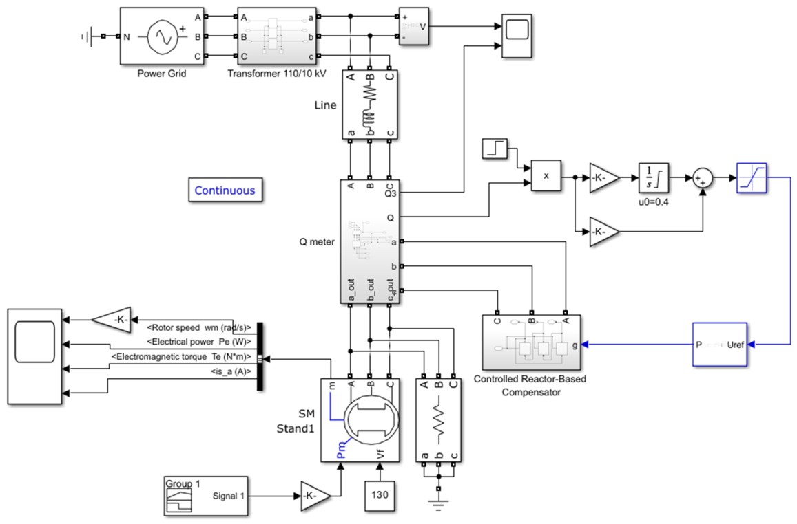
The model of a section of the modernized shop power supply system, containing a controlled reactor compensator (controlled reactor-based compensator) with a closed-loop reactive power control system, is shown in Figure 14.
Figure 14.
Mathematical model of the modernized section of the power supply system with a controlled reactor compensator and a closed-loop reactive power control system.
An architecture with reactive power feedback and a reactive power PI controller was used as a closed-loop reactive power control system. The reactive power PI controller was tuned assuming a linear dependence of the filter reactive power on the control signal . The possibility of such linearization is shown above in Figure 8c.
The results of calculations of dynamic modes of the modernized section of the shop power supply system of the CWBRM-1700 mill of JSC “Qarmet” with shock application of the load of the synchronous motor of stand No. 1 of the roughing group are shown in Figure 15. It should be noted that the compensator stabilized the voltage both in the no-load mode and during load surge. Voltage drops were reduced from 1300 V for 2.5–3 s to 400 V during a surge for 0.2–0.3 s and to 200 V during load shedding. Under load, the average voltage drop is only 1% . Reactive power fluctuations were reduced from 1.8 MVAR to 0.05 MVAR.
Figure 15.
Transient processes in the modernized power supply system of the CWBRM-1700 mill under shock application of load with a closed-loop reactive power control system.
The results obtained allow us to formulate the following important conclusions:
The closed-loop control system of reactive power in the mode of its stabilization at the zero level operates with high static indicators of the quality of regulation. At the moments of application and discharge of shock loads, minor fluctuations of reactive power occur. The amplitude values of fluctuations of reactive power are almost 20 times lower than the steady-state value of the reactive power consumed by the synchronous motor during the rolling process.
No less important is the influence of the controlled reactor compensator in the reactive power stabilization mode on the voltage quality in the load node. The use of the controlled reactor compensator allowed us to reduce the maximum voltage drop in the load node by 9% (from 10,000 to 9600 V versus a drop from 10,500 to 9200 V). The duration of the maximum voltage drop was also significantly reduced. The average voltage drops during rolling decreased by approximately 11% (100 V versus 1200 V).
Voltage stabilization provided by such a controlled reactive power compensator has become an additional and practically significant property of the system under consideration. This characteristic indicates that the compensator not only performs its main function of reactive power control and reduction in power losses but also contributes to maintaining the voltage level within the permissible limits during dynamic load variations. As a result, the compensator increases the overall electromagnetic compatibility and operational stability of the entire power supply system of the mill, especially under conditions of impact and cyclic loading typical for rolling processes.
This allows us to reasonably assume the possibility of operating the controlled reactor compensator as an effective voltage stabilizer in the load node. In this mode, the compensator can ensure the smooth restoration of the voltage amplitude after load disturbances and prevent dangerous voltage sags that could negatively affect the performance of electric drives and automation systems. Moreover, voltage stabilization in the rolling mill’s power network contributes to a more uniform energy distribution among the supply lines and enhances the reliability of technological equipment.
An important advantage of this operational mode lies in the fact that the implementation of voltage feedback for control purposes is considerably simpler, more reliable, and economically justified compared to the use of a reactive power sensor. The voltage feedback loop can be built using standard measuring and control elements, while reactive power control typically requires complex signal processing and additional instrumentation. Therefore, using a controlled reactor compensator as a voltage stabilizer represents a promising and technically feasible solution that can improve both dynamic and steady-state performance of the electric power supply system.
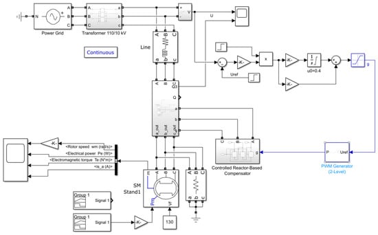
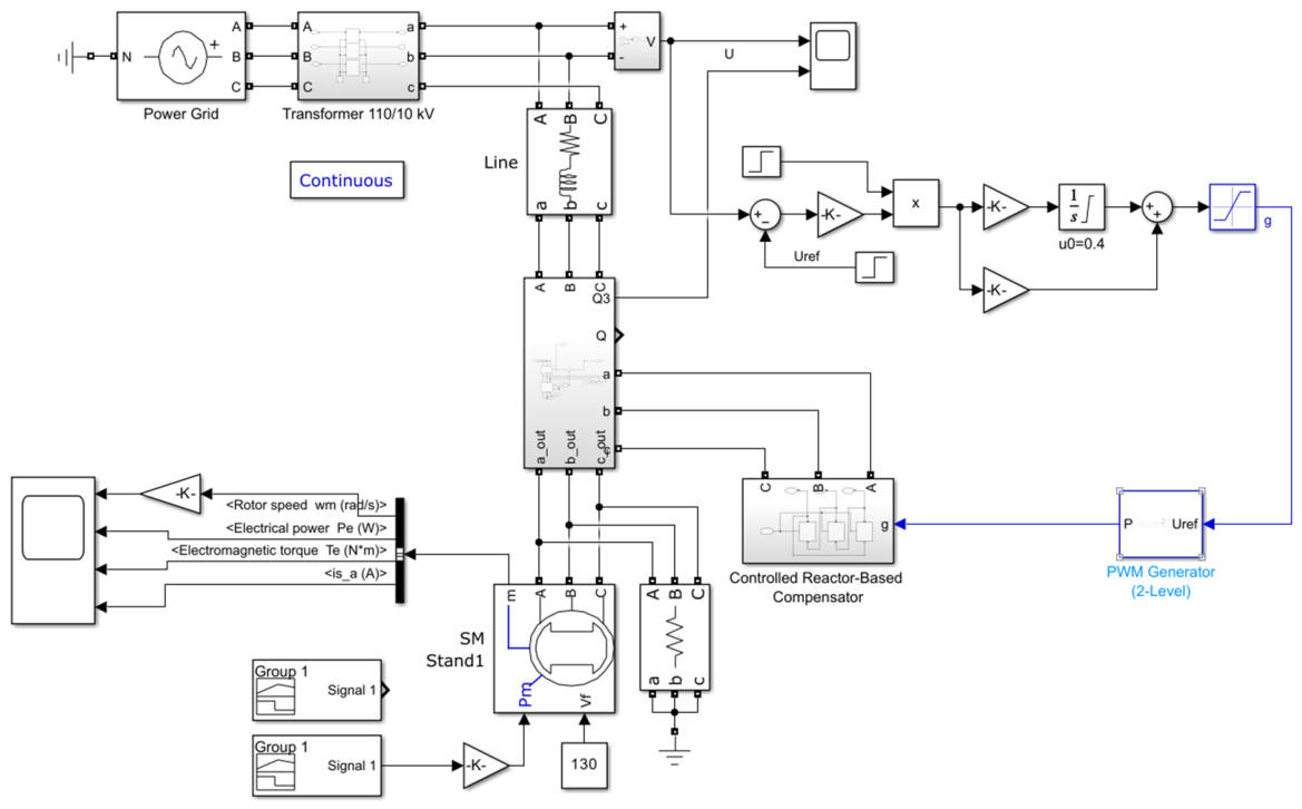
The model of a section of the modernized shop power supply system, containing a controlled reactor compensator (controlled reactor-based compensator) with a closed-loop load voltage control system, is shown in Figure 16.
Figure 16.
Mathematical model of the modernized section of the power supply system with a controlled reactor compensator and a closed-loop voltage control system in the load node.
In this model, the reactive power measurement unit is only needed to visualize the dynamic modes of the shop power supply system section and is not used to control the reactor compensator.
The results of calculations of dynamic modes of the modernized section of the shop power supply system of the CWBRM-1700 mill of JSC “Qarmet” with voltage stabilization in the load node during shock application of the load of the synchronous motor of stand No. 1 of the roughing group are presented in Figure 17.
Figure 17.
Transient processes in the modernized power supply system of the CWBRM-1700 mill under shock application of load with a closed-loop control system for the voltage of the load node.
It is evident that the proposed system functions successfully, providing the same high quality of voltage stabilization in the network node as the reactive power compensator: the maximum voltage drop in the load node of less than 400 V lasts less than 0.5 s. The steady-state value exactly corresponds to the specified one—10,000 V. Voltage stabilization during load surge occurs due to reactive power overcompensation to −0.15 MVAR.
The main indicators of the original and proposed systems are compared in Table 2.
Table 2.
Comparison of voltage and reactive power parameters for the original and improved power supply systems.
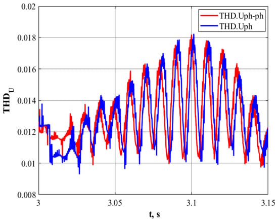
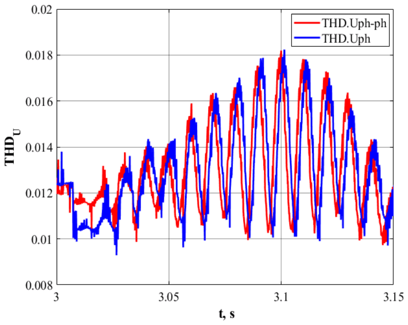
The use of a controlled reactor compensator can potentially introduce additional distortions into the network voltage shape. Therefore, additional studies were conducted on the dependence of the harmonic distortion coefficient THD of the network voltage during the rolling process. The results obtained are illustrated in Figure 18.
Figure 18.
Change in THD of line and phase voltages at the moment of load surge.
The proposed controlled reactor compensator makes minor changes to the shape of the network voltage. Due to the delta connection and the choice of the switching frequency, a multiple of 3 × 50 (27 × 50 Hz), the maximum distortion of the harmonic composition of the linear and phase voltages does not exceed 1.5…2% even at the moment of load surge (Figure 18).
4. Results and Discussion
The study of the power distribution network of the CWBRM-1700 hot rolling mill showed that the main problems of power quality are associated with dynamic changes in reactive power during the operation of high-power synchronous motors. During rolling, especially at the moments when the slab is captured by the rolls, short-term voltage drops of up to 13% of the nominal value were recorded. These fluctuations lasted on average 5–6 s and were accompanied by waveform distortions, confirming the presence of pronounced transient processes and low electromagnetic stability of the supply system.
To perform a deeper analysis, a mathematical simulation model was developed in the MATLAB Simscape Electrical environment (The MathWorks, Inc., Natick, MA, USA), fully reproducing the structure and operating modes of the workshop network fragment. The simulation results were in close agreement with the experimental data, which made it possible to reliably identify the main cause of instability–sharp variations in reactive power in the range of −0.5 to +0.5 MVAR, occurring during the start-up and impact loading of synchronous drives.
The next stage was the investigation of the efficiency of a controlled reactor-based compensator (CRBC) based on a three-phase LLC-type filter with diode–transistor keys. Adjustment of the electromagnetic parameters of the device ensured a linear relationship between the control signal and the reactive power value, while harmonic distortion was reduced through a delta (Δ) connection of the windings and a pulse width modulation (PWM) frequency equal to a multiple of the tripled grid frequency (3 × 50 Hz).
Modeling demonstrated that the introduction of the CRBC significantly improves voltage stability and reduces the amplitude of reactive power fluctuations. In the reactive power stabilization mode, the system effectively compensated for dynamic deviations: the reactive power pulsations decreased almost 40-fold—from 1.8 MVAR to 0.05 MVAR—and the voltage sag amplitude decreased from 1300 V to 400 V, with a transient time not exceeding 0.3 s. Thus, the compensator effectively suppresses instantaneous reactive surges, stabilizing voltage even under impact loads.
An alternative control strategy—voltage stabilization with feedback—demonstrated similar efficiency. In this case, regulation was achieved without measuring reactive power, which simplifies practical implementation. Under this control mode, the voltage at the load node was maintained at 10 kV with deviations not exceeding ±3–4%, and the transient time was about 0.5 s. Therefore, both control strategies provide stable system behavior under dynamic disturbances; however, the voltage-stabilization mode may be preferable for industrial operation due to its simpler hardware configuration.
Special attention was paid to the possible influence of the compensator on the harmonic composition of the voltage. Spectrum analysis showed that, due to the Δ-connection and optimal selection of the switching frequency, waveform distortion remained insignificant: the total harmonic distortion (THD) did not exceed 1.5–2%, even at peak loads. This fully complies with the requirements of IEC 61000 and IEEE-519 standards for industrial power networks.
The practical interpretation of the results confirms that the application of the controlled reactor-based compensator provides a qualitatively new level of electromagnetic compatibility for hot rolling equipment. Voltage stabilization within the distribution network enhances the reliability of electric drives, reduces the risk of control system failures, and decreases the frequency of unplanned downtimes. In a continuous production cycle, these effects have a direct economic impact by minimizing time and energy losses and extending equipment lifetime.
Overall, the results of modeling and analysis indicate that the use of adaptive compensating devices with closed-loop control systems makes it possible not only to eliminate short-term voltage sags but also to achieve an optimal balance between power quality and technical simplicity. Thus, the proposed approach opens up opportunities for further improvement of energy efficiency and electromagnetic compatibility in next-generation metallurgical production systems.
5. Conclusions
In the work, based on the analysis of the general features of the hot rolling mill CWBRM-1700 of JSC “Qarmet”, the main factors that negatively affect the operation of the shop distribution network of power supply are identified. These factors include the high installed capacity of the equipment, which causes significant reactive power flows in the distribution network, and shock loads of powerful technological mechanisms, leading to voltage drops.
- During the experimental study of the voltage quality on the 10 kV substation buses, the main assumptions about the fairly low voltage quality in the power distribution network of the hot rolling mill CWBRM-1700 were confirmed. It was found that shock loads of synchronous electric drives of roughing stands lead to periodic voltage drops from 10,500 to 9200 V, which is 13% of the nominal value. The duration of the voltage drop coincides with the duration of slab rolling in the stand and it is ~ 5–6 s.
- To determine the causes of low voltage quality, a mathematical model of a section of a distribution network was developed in the MATLAB R2024a/Simscape/Electrical environment, including a motor load in the form of a synchronous motor with a capacity of 4200 kW. The results of mathematical modeling coincide with the data of the experimental study with high accuracy. Analysis of the modeling results showed that the most significant factor affecting the quality of electrical energy is rapid changes in reactive power −0.5 to +0.5 MVAR.
- To compensate for such pulsations, it is proposed to use a three-phase adjustable reactor compensator according to the LLC filter circuit with diode–transistor keys. The paper proposes for the first time a method for calculating the electromagnetic parameters of such a filter, which ensures a linear change in the compensated reactive power in a given range and establishes that in order to reduce the level of harmonic distortion of voltage, it is necessary to use a triangle connection of the controlled reactive compensator and select the PWM frequency of the transistors, a multiple of the tripled frequency of the power grid.
- Two main options for creating a closed-loop control system for the energy modes of the distribution network of the hot rolling mill power supply are proposed: a reactive power stabilization system and a voltage stabilization system.
- 4.1
- It is shown that the closed-loop reactive power stabilization system based on the PI controller ensures a decrease in reactive power fluctuations during rolling from 1.8 MVAR to 0.05 MVAR, voltage fluctuations in the load node also decreases from 1300 V for 5–6 s to 400 V for 0.2–0.5 s during load surge and to 200 V during load shedding. Under load, the average voltage drop is only 1%.
- 4.2
- A voltage stabilization system reduces the voltage drop in the network node to –4 to + 3%. The advantage of this system is the ability to use a technically less complex voltage sensor.
The proposed solutions will reduce the costs of maintenance and spare parts, reduce the risk of unscheduled downtime, which in the first half of 2025 alone at the 1700 mill amounted to 4 h, including unscheduled downtime—30.62%—and technical downtime—69.38%—which is critically important for a continuous production cycle.
Further research could be aimed at a more in-depth study of the interaction of several electric drives of different types—based on synchronous machines in roughing mill drives and DC drives in finishing rolling and cutting mills or high-voltage soft starter devices [16,17,35,36].
Author Contributions
Conceptualization, A.S. and A.B.; methodology, A.S. and A.B.; software, A.S. and A.B.; validation, K.S. and A.B.; formal analysis, A.S. and V.K.; investigation, V.K. and K.S.; resources, Z.G. and Z.B.; data curation, Z.G. and Z.B.; writing—original draft preparation, A.S. and A.B.; writing—review and editing, A.B.; visualization, O.B.; supervision, Z.G.; project administration, V.K.; funding acquisition, O.B. All authors have read and agreed to the published version of the manuscript.
Funding
This research received no external funding.
Data Availability Statement
The original contributions presented in this study are included in the article. Further inquiries can be directed to the corresponding authors.
Conflicts of Interest
The authors declare no conflicts of interest. In the author affiliations, ‘NPJSC’ represents the official legal form of organization of the universities, and no commercial companies were involved in this study.
Abbreviations
The following abbreviations are used in this manuscript:
| CWBRM | Continuous wide-band rolling mill |
| MSS | Main step-down substation |
| AM | Asynchronous motor |
| AVI | Autonomous voltage inverter |
| ACI | Autonomous current inverter |
| HF | High frequencies |
| TODTK | Two-operational diode–transistor key |
| DTK | Diode–transistor key |
| EMI | Electromagnetic interference |
| EMC | Electromagnetic compatibility |
| EMF | Electromotive force |
| SC | Short circuit |
| CFCD | Controlled filter-compensating device |
| CRBC | Controlled reactor-based compensator |
| UR | Uncontrolled rectifier |
| LF | Low frequencies |
| PFCD | Passive filter-compensating device |
| FC | Frequency converter |
| QoEP or PQ | Quality of electric power |
| QE | Quality of electricity |
| IPQ | Indicators of electric power quality |
| RC | Reactor compensator |
| RP | Reactive power |
| RF | Resonant filter |
| RCD | Reactor compensating device |
| ACS | Automatic control system |
| PSC | Power semiconductor converter |
| WPSN | Workshop power supply network |
| SC | Semiconductor converter |
| TC | Thyristor converter |
| FCD | Filter-compensating device |
| PWM | Pulse width modulation |
| PWR | Pulse width regulation |
References
- Mohanty, A.; Ray, P.K.; Das, S.R.; Soudagar, M.E.M.; Ramesh, S.; Khan, T.M.Y.; Almakayeel, N.; Ali, M.M.; Bashir, M.N. Enhancing power quality in contemporary utility systems: A comprehensive analysis of active power filters and control strategies. Energy Rep. 2024, 11, 5575–5592. [Google Scholar] [CrossRef] [Scilit]
- Nor, K.A.M.; Abdullah, N. Power quality improvement of three-phase electrical systems using active-passive hybrid harmonic filter. Results Eng. 2024, 22, 102242. [Google Scholar] [CrossRef] [Scilit]
- Araoye, T.O.; Ashigwuike, E.C.; Adeyemi, A.C.; Egoigwe, S.V.; Ajah, N.G.; Eronu, E. Reduction and control of harmonic on three-phase squirrel cage induction motors with voltage source inverter (VSI) using ANN-grasshopper optimization shunt active filters (ANN-GOSAF). Sci. Afr. 2023, 21, e01785. [Google Scholar] [CrossRef] [Scilit]
- Karthikeyan, M.; Sharmilee, K.; Balasubramaniam, P.M.; Prakash, N.B.; Babu, M.R.; Subramaniyaswamy, V.; Sudhakar, S. Design and implementation of ANN-based SAPF approach for current harmonics mitigation in industrial power systems. Microprocess. Microsyst. 2020, 77, 103194. [Google Scholar] [CrossRef] [Scilit]
- El Ghaly, A.; Tarnini, M.; Al Barakeh, Z.; Chahine, K. Compensating voltage waveform distortions using a practical topology of series active power filters. Results Eng. 2024, 22, 102032. [Google Scholar] [CrossRef] [Scilit]
- Govind, A.; Jayaswal, K.; Tayal, V.K.; Kumar, P. Simulation and real time implementation of shunt active power filter for power quality enhancement using adaptive neural network topology. Electr. Power Syst. Res. 2024, 228, 110042. [Google Scholar] [CrossRef] [Scilit]
- Hingol, H.; Deshpande, V.; Sant, A.V. Modified symmetrical sinusoidal integrator and instantaneous reactive power theory-based control of shunt active filter. Energy Rep. 2022, 8, 515–523. [Google Scholar] [CrossRef] [Scilit]
- Toumi, T.; Allali, A.; Meftouhi, A.; Abdelkhalek, O.; Benabdelkader, A.; Denai, M. Robust control of series active power filters for power quality enhancement in distribution grids: Simulation and experimental validation. ISA Trans. 2020, 107, 350–359. [Google Scholar] [CrossRef] [Scilit] [PubMed]
- Chu, Y.; Luo, X.; Hou, S.; Fei, J. Robust hybrid intelligent control using probabilistic feature for active power filter. Control Eng. Pract. 2023, 141, 105712. [Google Scholar] [CrossRef] [Scilit]
- Sathish Babu, P.; Balasundar, C.; Sundarabalan, C.K. ANFIS controlled fuel cell powered series active filter for voltage waveform augmentation in the distribution grid, e-Prime—Advances in Electrical Engineering. Electron. Energy 2024, 7, 100425. [Google Scholar] [CrossRef] [Scilit]
- Pérez-Ramírez, J.; Montoya-Acevedo, D.; Gil-González, W.; Montoya, O.D.; Restrepo, C. Shunt active power filter using model predictive control with stability guarantee, e-Prime—Advances in Electrical Engineering. Electron. Energy 2025, 12, 101029. [Google Scholar] [CrossRef] [Scilit]
- Acharya, S.; Kumar, D.V. Power quality enhancement in grid tied hybrid system using chicken swarm optimization algorithm optimized shunt filter. J. Energy Storage 2025, 128, 117112. [Google Scholar] [CrossRef] [Scilit]
- Bakria, D.; Laouid, A.A.; Korich, B.; Beladel, A.; Teta, A.; Mohammedi, R.D.; Elsayed, S.K.; Ali, E.; Aeggegn, D.B.; Ghoneim, S.S.M. An optimized shunt active power filter using the golden Jackal optimizer for power quality improvement. Sci. Rep. 2025, 15, 15869. [Google Scholar] [CrossRef] [Scilit] [PubMed]
- Greber, M.; Fodor, A.; Magyar, A. Phase current estimation based shunt active power compensation. IFAC-PapersOnLine 2022, 55, 48–53. [Google Scholar] [CrossRef] [Scilit]
- AlDubey, K.; Mishra, J.P.; Kumar, A. Comparative Analysis of ROGI based Shunt Active Power Filter under Current Fed and Voltage Fed Type Non-Linear Loading Condition. IFAC-PapersOnLine 2022, 55, 156–161. [Google Scholar] [CrossRef] [Scilit]
- Batyrbek, A.; Kuznetsov, V.; Kuznetsov, V.; Rojek, A.; Kovalenko, V.; Tkalenko, O.; Tytiuk, V.; Krasovskyi, P. Control of Drum Shear Electric Drive Using Self-Learning Artificial Neural Networks. Energies 2025, 18, 5763. [Google Scholar] [CrossRef] [Scilit]
- Busher, V.; Kuznetsov, V.; Ciekanowski, Z.; Rojek, A.; Grudniewski, T.; Druzhinina, N.; Kuznetsov, V.; Tryputen, M.; Hubskyi, P.; Batyrbek, A. Development of a Digital Twin of a DC Motor Using NARX Artificial Neural Networks. Energies 2025, 18, 6502. [Google Scholar] [CrossRef] [Scilit]
- Tytiuk, V.; Chornyi, O.; Zachepa, Y.U.; Kuznetsov, V.; Tryputen, M. Control of the Start of High-Powered Electric Drives with the Optimization in Terms of Energy Efficiency. Nauk. Visnyk Natsionalnoho Hirnychoho Universytetu 2020, 5, 101–108. [Google Scholar] [CrossRef] [Scilit]
- Busher, V.; Chornyi, O.; Glazeva, O.; Kuznetsov, V.G.; Tytiuk, V.; Tryputen, M. Optimal Control Method of High-Voltage Frequency Converters with Damaged Cells. IOP Conf. Ser. Mater. Sci. Eng. 2020, 985, 012021. [Google Scholar] [CrossRef] [Scilit]
- Electronpribor. Resurs-UF2M-3T52-5-100-1000—Power Quality Analyzer. Available online: https://www.electronpribor.ru/catalog/16/resurs-uf2m-3t52-5-100-1000.htm (accessed on 15 May 2026).
- Keller, R.B. Design for Electromagnetic Compatibility—In a Nutshell, Theory and Practice; Springer: Berlin/Heidelberg, Germany, 2023. [Google Scholar] [CrossRef] [Scilit]
- Mahesh, G.S.; Mohan, C.V.; Nagesh, B.K.; Dillibabu, G. Sustainable and Optimized Harmonic Filter Design for Industrial Loads. Procedia Comput. Sci. 2023, 230, 780–787. [Google Scholar] [CrossRef] [Scilit]
- Dixon, J.; Moran, L.; Rodriguez, J.; Domke, R. Reactive power compensation technologies: State of the art review. Proc. IEEE 2005, 93, 2144–2164. [Google Scholar] [CrossRef] [Scilit]
- Zhuk, O.; Zhuk, D.; Kryvoruchko, D.; D’yakonov, O. Control of Improved Hybrid Power Line Conditioner. In Proceedings of the 2018 IEEE 38th International Conference on Electronics and Nanotechnology (ELNANO), Kyiv, Ukraine, 24–26 April 2018; pp. 605–610. [Google Scholar]
- Zhuk, O.; Trybulkevich, S.; Zhuk, D. Ryabenkij Modeling of a FilterCompensating Device with a Controlled Reactor Compensator. In Proceedings of the 7th International Conference on Digital Technologies in Education, Science and Industry, DTESI, Almaty, Kazakhstan, 20–21 October 2022; pp. 313–324. [Google Scholar]
- Zhuk, O.; Zhuk, D.; Kryvoruchko, D.; Stepenko, S. An improvement of compensators of complete power non-active components in autonomous electric power systems. In Proceedings of the 2016 2nd International Conference on Intelligent Energy and Power Systems (IEPS), Kyiv, Ukraine, 7–11 June 2016; pp. 1–5. [Google Scholar]
- Busher, V.; Zakharchenko, V.; Shestaka, A.; Kuznetsov, V.; Kuznetsov, V.; Nader, S. Optimization of the Control of Electromagnetic Brakes in the Stand for Tuning Internal Combustion Engines Using ID Regulators of Fractional Order. Energies 2022, 15, 9378. [Google Scholar] [CrossRef] [Scilit]
- Dymerets, A.V.; Yershov, R.D.; Gorodny, A.N.; Denisov, Y.O.; Boiko, S.; Kuznetsov, V. Dynamic Characteristics of Zero-Current-Switching Quasi-Resonant Buck Converter under Variation of Resonant Circuit and Load Parameters. In Proceedings of the 2020 IEEE 40th International Conference on Electronics and Nanotechnology (ELNANO), Kyiv, Ukraine, 22–24 April 2020; pp. 848–853. [Google Scholar] [CrossRef] [Scilit]
- Yevheniia, K.; Vitaliy, K.; Mykola, T.; Alisa, K.; Maksym, T.; Mykola, B. Development and Verification of Dynamic Electromagnetic Model of Asynchronous Motor Operating in Terms of Poor-Quality Electric Power. In Proceedings of the 2019 IEEE International Conference on Modern Electrical and Energy Systems (MEES), Kremenchuk, Ukraine, 23–25 September 2019; pp. 350–353. [Google Scholar] [CrossRef] [Scilit]
- Tetiana, S.; Vitaliy, K.; Yevheniia, K. About Electromagnetic Compatibility of Rail Circuits With the Traction Supply System of Railway. In Proceedings of the 2018 IEEE 3rd International Conference on Intelligent Energy and Power Systems (IEPS), Kharkiv, Ukraine, 10–14 September 2018; pp. 59–63. [Google Scholar] [CrossRef] [Scilit]
- Romashykhin, I.; Rudenko, N.; Kuznetsov, V. The possibilities of the energy method for identifying the parameters of induction motor. In Proceedings of the 2017 International Conference on Modern Electrical and Energy Systems (MEES), Kremenchuk, Ukraine, 15–17 November 2017; pp. 128–131. [Google Scholar] [CrossRef] [Scilit]
- Chenchevoi, V.; Kuznetsov, V.; Kuznetsov, V.; Chencheva, O.; Zachepa, I.; Chornyi, O.; Kovzel, M.; Kovalenko, V.; Babyak, M.; Levchenko, S. Development of Mathematical Models of Energy Conversion Processes in An Induction Motor Supplied from An Autonomous Induction Generator with Parametric Non-Symmetry. East.-Eur. J. Enterp. Technol. 2021, 4, 59–66. [Google Scholar] [CrossRef] [Scilit]
- Tryputen, N.; Kuznetsov, V.; Kuznetsova, Y. About the Possibility of Researching the Optimal Automatic Control System on a Physical Model of a Thermal Object. In Proceedings of the 2019 IEEE 2nd Ukraine Conference on Electrical and Computer Engineering (UKRCON), Lviv, Ukraine, 2–6 July 2019; pp. 1244–1248. [Google Scholar] [CrossRef] [Scilit]
- Tryputen, M.; Kuznetsov, V.; Kuznetsov, V.; Kuznetsova, Y.; Tryputen, M.; Kuznetsova, A. Laboratory Bench to Analyze an Automatic Control System with a Fuzzy Controller. Diagnostyka 2020, 21, 61–68. [Google Scholar] [CrossRef] [Scilit]
- Busher, V.; Chornyi, O.; Tytiuk, V.; Glazeva, O.; Shestaka, A.; Melnikova, L. Research of Electromagnetic and Electromechanical Processes in High-Voltage Soft Start Devices with Gate Turn-Off Thyristors. In Proceedings of the 2023 IEEE 5th International Conference on Modern Electrical and Energy System (MEES), Kremenchuk, Ukraine, 27–30 September 2023; pp. 1–5. [Google Scholar] [CrossRef] [Scilit]
- Busher, V.; Zakharchenko, V.; Glazeva, O.; Khandakji, K. Provision of electromagnetic compatibility of a high-power soft starter with vessel’s power system in dynamic modes. Tech. Electrodyn. 2019, 2019, 29–33. [Google Scholar] [CrossRef] [Scilit]

Disclaimer/Publisher’s Note: The statements, opinions and data contained in all publications are solely those of the individual author(s) and contributor(s) and not of MDPI and/or the editor(s). MDPI and/or the editor(s) disclaim responsibility for any injury to people or property resulting from any ideas, methods, instructions or products referred to in the content. |
© 2026 by the authors. Licensee MDPI, Basel, Switzerland. This article is an open access article distributed under the terms and conditions of the Creative Commons Attribution (CC BY) license.