


Abstract
Many researchers are interested in the behavior of voided concrete members, which are used to increase flexural capacity by increasing the section depth. However, few studies have concerned ways to expand the voids to increase the self-weight loss while maintaining the permitted carrying capacity of these members. This study deals with the effect of a void scheme to further reduce the weight of glass fiber-reinforced polymer (GFRP) one-way reinforced concrete (RC) slabs by benefiting from the anti-classical curvature of one-way RC slabs. This study also incorporates green structures by using non-degradable plastic bottles in the RC one-way slabs. Three void configurations are used in this study: straight-line, back-to-back, and front-to-front void schemes. Specimens with the straight-line void configuration achieve the highest ultimate load capacity, reaching 91% of the solid reference slab’s capacity if reinforced near the minimum reinforcement ratio and 101% if used with a 30% larger GFRP reinforcement ratio. The back-to-back curved configuration is identified as the most efficient design, providing a 10.3% reduction in self-weight while retaining 83% of the solid slab’s ultimate load capacity, as compared with the front-to-front configuration, which retains only 73%.
1. Introduction
Solid reinforced concrete slabs are an essential component of structural systems, particularly in framed structures and buildings. There are two primary types of solid slabs: one-way slabs and two-way slabs [1,2]. The most recent trend involves creating a voided slab, which decreases the slab’s self-weight while maintaining the same level of efficiency. Recently, the concepts of sustainability and recycling of plastic waste have spread as a way to reduce environmental pollution on this planet [3]. However, a significant percentage of the anticipated global daily output of billions of single-use polyethylene terephthalate (PET) bottles are not recycled. As a result, having multiple uses for such bottles would have a significant impact on decreasing plastic waste. Autoclaving is not suggested for PET, but other (gas) sterilization procedures are acceptable. In various end-of-life scenarios (reuse, recycling, or re-manufacture), the “Energy End of Life” potential is a measure of the energy that may be recovered at the conclusion of a product’s life, even with a single reuse of a standard used PET bottle. To maximize this potential, many researchers have studied the use of waste PET bottles in engineering applications, such as in the manufacturing of one-way voided RC slabs.
A one-way voided slab is a type of reinforced concrete beam that has hollow cores in the middle. This reduces the load of the beam and allows it to span an extra distance. The voids are created by placing prefabricated concrete blocks into the formwork before the concrete is poured. The blocks are then eliminated after the concrete has cured. Voided slabs are often utilized in bridges and different systems where weight is a chief concern. Voids are regularly and cautiously organized to ensure that there is enough concrete around important stress zones, mainly close to the top and bottom fibers in which bending stresses are highest. Reinforcements are generally located in areas of solid concrete to control cracking and improve flexural ability.
Numerous studies have addressed this subject and examined the different properties, efficiency, loads, void shapes, sizes, and proportions; the kinds of material used to create voids; and the ratio of voids to slabs [4,5].
Dadzie & Kaliluthin, 2022, investigated the cost of using waste plastic bottles in the production of voided concrete slabs, compared the depth ratio to the cost savings of using waste plastic bottles in the production of voided concrete slabs, analyzed the energy consumption and CO2 emissions caused by using waste plastic bottles in the production of voided concrete slabs, and assessed the effect of the depth ratio on embodied energy consumption and CO2 emission [4]. As part of the results, it was discovered that adding used plastic bottles to concrete slabs lowers the required volume and cost of concrete. Once more, incorporating recycled plastic bottles into the slabs reduced costs; nonetheless, the cost increased with the percentage of bottles used because more labor and resources (plastic bottles, chicken wire, etc.) were required.
A voided slab is composed of hollow plastic voids that are placed inside the slab soffit between the tension and compression steel reinforcements. There are several different shapes for voids, including cuboids, cylinders, spheres, hexahedra, and donuts. Plastic trash has recently been used in voided slabs to reduce environmental pollution and the slabs’ self-weight, thus promoting sustainability, solid waste treatment, and environmental preservation [5,6]. While many types of void shapes are basic-shaped (spherical, elliptical, and cubic) cells, there are also other types of voids, such as those that have curvature in their edge radii and hole diameters in their top and bottom surfaces. The idea behind voided slabs is to remove the inefficient concrete from the core of a flexural slab and replace it [7,8] with hollow plastic formers. The stress distribution of a voided reinforced concrete one-way slab is like that of a solid slab section, but the strain is discontinuous at the void zone depth. The stresses are explained through tension (i.e., below the neutral axis (N.A)) and the stress block of compression (i.e., concrete above the N.A).
Chung et al., in 2011 [9], adopted a donut-type voided slab and conducted bond experiments to assess the bond properties of the deformed steel bars in the slab. Based on their findings, an equation was also put forth to determine the bond strength of the donut-type voided slab while taking into account the bond properties of each region in relation to the void morphologies and inner cover thickness. The calculated bond strength of the donut-type voided slab was confirmed to be highly accurate by the analytical results, which showed that the error range between the estimated and experimental values was within 5%.
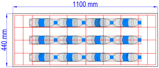
Fazaa Rajab et al. [10], in 2022, examined the flexural strength, ductility, stiffness, and toughness of RC hollow one-way slabs with plastic bottle voids, as shown in Figure 1. To create a straight-line tube, a steel mesh tube was first manufactured and then manually filled with empty waste plastic bottles using a novel hollowing technique. Easy installation and sufficient bonding for the primary steel reinforcements are two benefits of this technology. An innovative method was adopted to cast the voided RC slabs, using waste PET water bottles fixed using rolled steel meshes inside the slab. The dimensions of the one-way RC slabs were 400 mm (width) × 1100 mm (length).
Figure 1.
Details of a voided slab [10].
The voided specimens’ ductility was enhanced by roughly 100% for the same section thickness. Additionally, a 15% increase in the thickness of the voided slab resulted in a 30% reduction in support rotation [7,11,12,13,14].
Orientilize et al., 2021 studied the properties of straight hollow-core slabs (HCSs) formed from used plastic bottles [15]. Polyethylene terephthalate (PET) was used to make the bottles. Shredded PET was also added to the concrete mixture to increase the HCSs’ strength as part of green research to repurpose waste materials. There would be no problems in building cast-on-site HCSs. The impacts of the void content, shredded PET content, and steel fiber (SF) content on the HCSs’ ultimate bending capacity (Mu) were the three factors that were examined. Static loads were applied to 15 specimens until they failed, and the outcomes were contrasted with those for solid slabs. The two void contents that were examined were 19% and 24% [11].
The SF content (0.19% and 0.32%) and the shredded PET content (0.5% and 0.7%) were the additional parameters. Compared with those for the solid slab, the HCS specimens’ Mu values were 12% to 16% lower. The strength, however, remained within the theoretical bounds for the solid slab. Compared with that of the solid slab, the HCSs’ bending capacity was increased by 18% to 38% with the inclusion of shredded PET. The specimens containing SFs likewise showed similar results, with Mu values that were 11% to 46% higher than those of the solid slab [15].
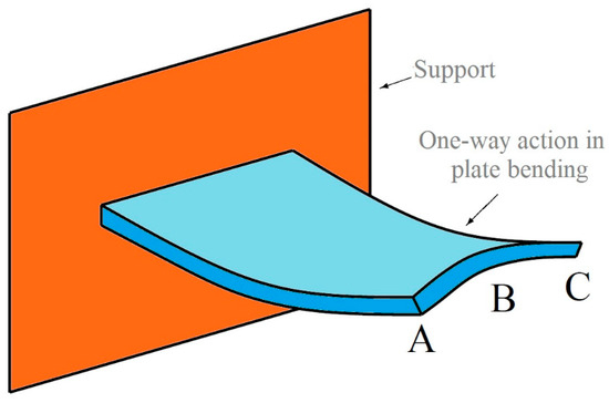
In many RC one-way slab investigations, increased strain magnitude in the center bars compared with the corner bars has been mentioned by researchers [16]. Figure 2 explains the anti-classic bending effect through a conceptual illustration of the effect on a plate as it bends. As shown, as the plate bends upward, the compression in the top half and tension in the bottom half lead its outside corners, points A and C, to move a smaller distance than its center, point B. The analytical model estimates tip displacement by averaging deformations over the bending element’s breadth. If the anti-classic effect is sufficiently significant in proportion to the longitudinal bending of the plate, the predicted tip displacement will be zero.
Figure 2.
Conceptual view of anti-classic bending in a one-way action plate.
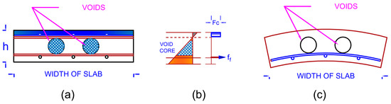
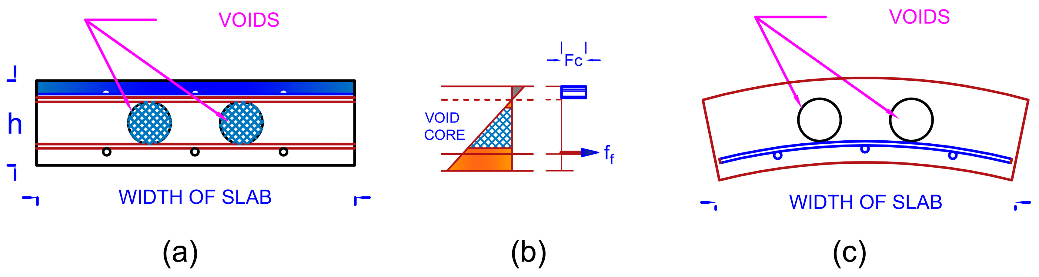
In the rectangular one-way slab section illustrated in Figure 3a, the direct stress distribution due to vertical bending ranges from greatest compression in the higher layers of the beam to tension in the lower layers of the beam, as indicated in Figure 3b. Because of the Poisson effect, compressive stress causes lateral elongation of the highest fiber of the beam cross-section, whereas tensile stress causes lateral contraction of the lowest fiber (soffit) of the slab cross-section. As a result, the section deforms as illustrated in Figure 3c, a phenomenon known as anti-classic bending [17]. For strength-driven applications, GFRP reinforcement consistently offers the most cost-effective solution due to its low material cost, as reported in [18].
Figure 3.
Anti-classic bending of a one-way slab section: (a) Voided Slab section, (b) Stress distributions along section’s depth, (c) deflected shape of section.
The term “anti-classical curvature” in the context of one-way slabs refers to the development of principal moments and curvatures that are not aligned with the primary spanning direction. When a one-way slab is loaded, it exhibits primary curvature along its span. However, due to Poisson’s effect and the plate behavior of the slab, a secondary, opposing (anti-classical) curvature develops in the transverse direction. This results in a three-dimensional stress state within the slab. It is hypothesized that by strategically placing voids in curved configurations, the void geometry can be better aligned with these complex stress trajectories, potentially minimizing the disruption to the load path and preserving flexural capacity more effectively than traditional straight voids. The symbols [()] and [)(] are used herein as simplified schematic representations of the curved void configurations adopted within the slabs, where the parentheses indicate the curvature profile of the internal void geometry. Anti-classic bending is relevant to the study of thin-walled box beams or slabs with stiffening ribs that retain the cross-sections. Avoiding anti-classic distortion causes local differences in stress distributions in the box section webs and coverings, as well as the stiffening ribs. In this study, intact PET bottles encaged with steel wire mesh are used as void tubes.
This study aims to meet the need for a void configuration that minimizes self-weight while better preserving structural performance, leading to enhanced thermal insulation and performance.
The novelty of this study is explained by the fact that the proposed curved configurations (back-to-back [)(] and front-to-front [()]) are inspired by the “anti-classical curvature” principle in one-way slabs. The novel hypothesis is that these specific curved shapes can better align with the internal stress trajectories (principal stresses) as compared with conventional straight voids, potentially mitigating the loss of capacity. The [)(] configuration, in particular, is hypothesized to act as a natural arching mechanism within the concrete, redistributing stresses more efficiently. A clearer distinction can be made between the proposed void configurations and previously reported systems (e.g., conventional straight-line or cylindrical voids). This study examines how the proposed configuration improves the load distribution, crack propagation control, and structural efficiency as compared with straight voided one-way slab systems, as mentioned in previous studies. To emphasize the potential benefits, bundled waste plastic bottles are used as a sustainable and structurally efficient void-forming material.
The main objective of this study is to investigate new curved voids, with forms such as inner closed curves [()] and outer opened curves [)(] made using waste PET bottles, that may benefit from anti-classical curvature performance (i.e., traverse curvature in the perpendicular direction due to bending stresses) in one-way slabs to increase the self-weight loss while maintaining the same capacity as one-way RC slabs.
2. Experimental Work
- ○
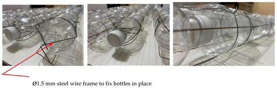
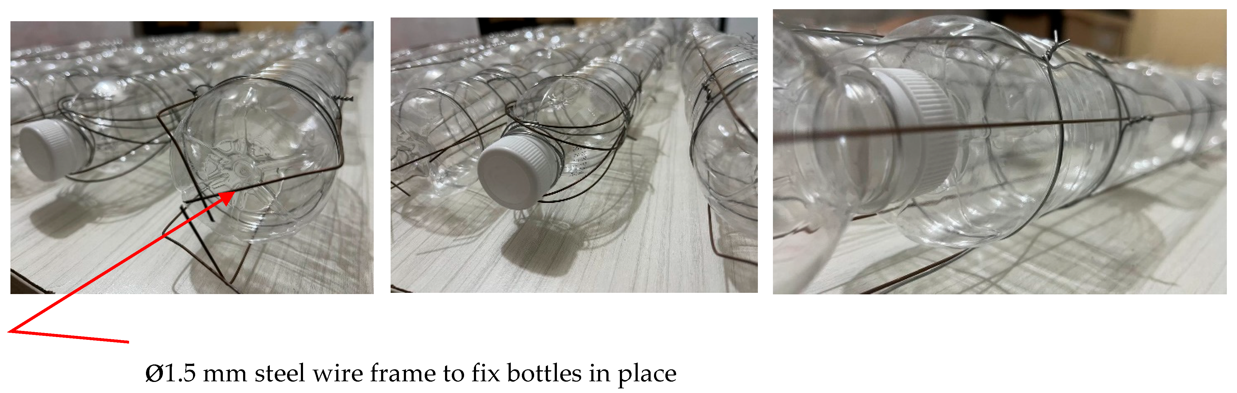
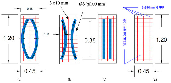
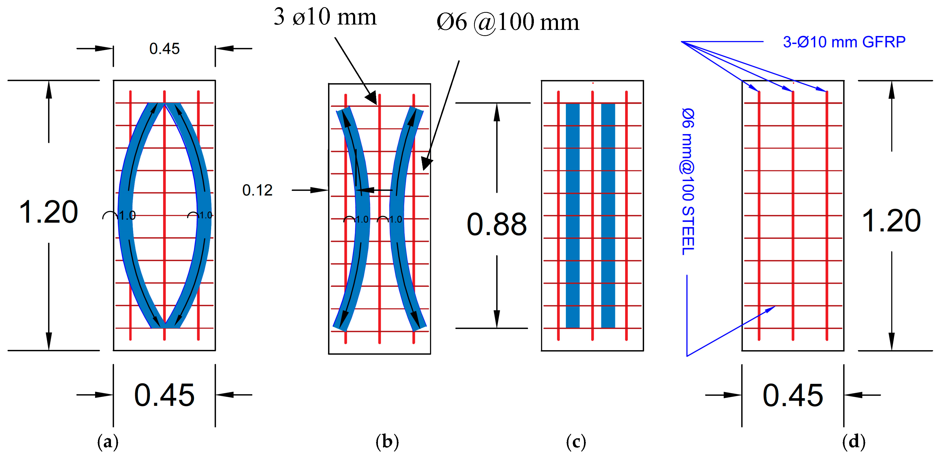
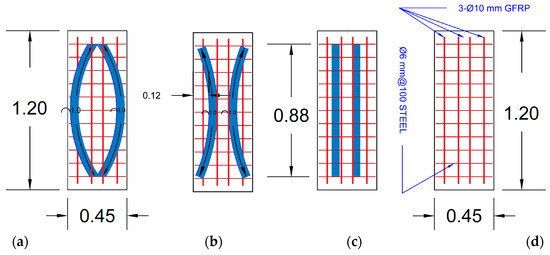
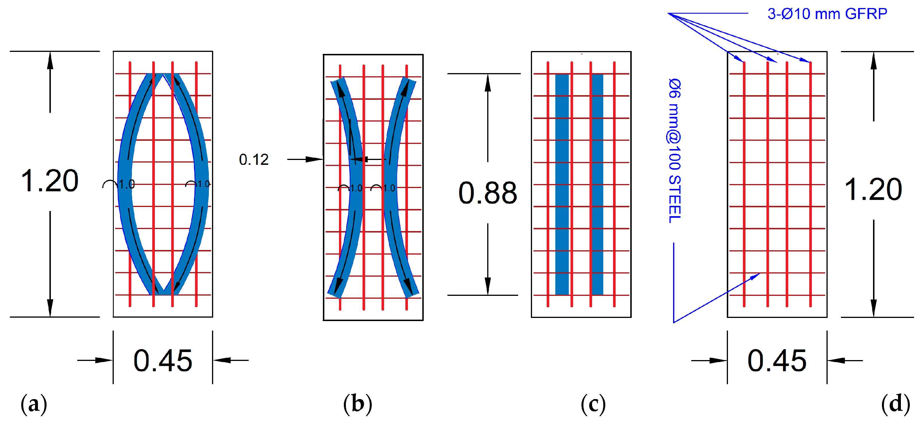
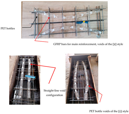
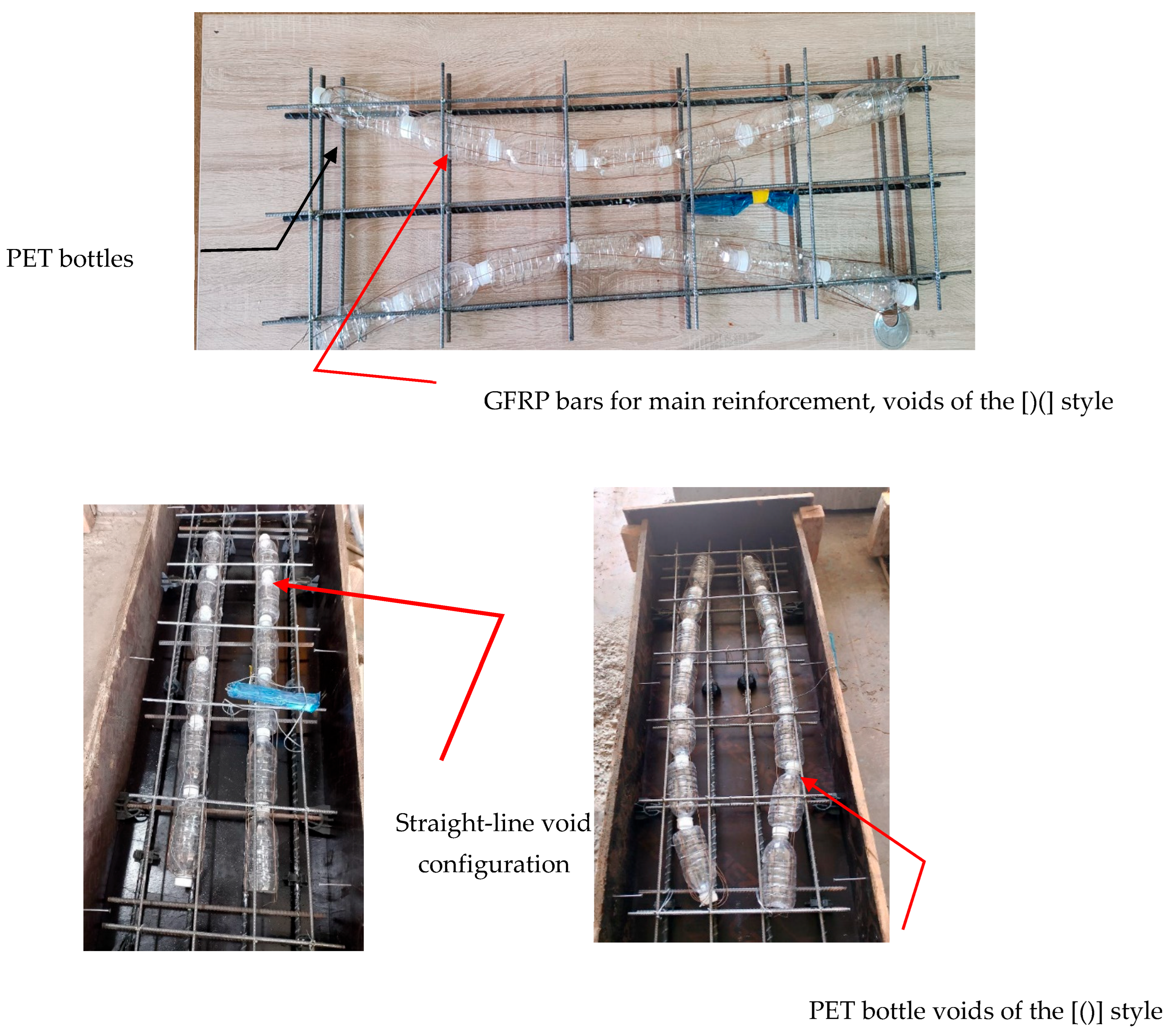
- A new method was used in this study to produce one-way voided slabs. Plastic water bottles were used in optimal arrangements to make voids in the slabs in different shapes as shown in Figure 4. To ensure that the bundled waste plastic bottles remained in their designated position during concrete pouring and vibration, they were tightly secured at multiple points along their length using annealed steel tie wire. This wire bundle was then securely fastened to the formwork’s bottom and sides to prevent any vertical or horizontal displacement. Eight models of one-way slabs with fixed dimensions (1.2 m long × 0.45 m wide × 0.12 m high) with different reinforcements and void shapes were constructed (Figure 5 and Figure 6); Table 1 provides all details of the tested specimens. Regular concrete mix was used with a mixing ratio of 1:2:4 and cast according to the ACI 211 specifications [19]. Then, ø10 mm GFRP bars and ø6 mm steel bars were used as longitudinal and width reinforcements, respectively (Figure 7). The actual average compressive strength of the concrete (f’c = 33 MPa) and its split tensile strength (ft = 3.2 MPa) were obtained by testing standard cylinders (150 × 300) mm on the day of slab testing. The modulus of elasticity (Ec) was calculated using standard ACI 318 formulas [20] based on the compressive strength and was nearest 27 GPa. The properties of the 10 mm diameter GFRP bars were tested at the structural engineering laboratory at the University of Anbar, Iraq, according to ASTM D7957 (2017). The ultimate tensile strength was 1024 MPa, elongation was 3.03%, and the elastic modulus was taken as 45 GPa. For the steel reinforcements used in the reference slabs, the yield strength was fy = 460 MPa, the tensile strength was fu = 660 MPa, and the modulus of elasticity (Es) as tested was 200 GPa.Figure 4. PET water bottle bundles.Figure 5. Slabs reinforced with three ø10 GFRP bars: (a) SG5()_R1; (b) SG6)(_R1; (c) SG3II_R1; (d) SG1_R1.Figure 6. Slabs reinforced with 4 bars: (a) SG7()_R2; (b) SG8)(_R2; (c) SG4II_R2; (d) SG2_R2.Table 1. The specimen details and properties.Figure 7. Shapes of voids in slabs.
- ○
- The properties of GFRP bars include their high tensile strength, light weight, and, most importantly, excellent corrosion resistance [21,22]. This corrosion resistance is a key driver of their use in structures where concrete cover might be reduced or where environmental exposure is a concern. This study used GFRP bars due to their light weight and strong bond with concrete in slim, voided concrete sections [23,24]. It has been used by many researchers, and it can be used in reinforcement skeletons with GFRP bars and steel as secondary reinforcements [25] due to recent developments in civil engineering, which have emerged with the introduction of global sustainable development ideas [26,27]. Achieving sustainability in building projects necessitates following the guidelines for employing recyclable, low-impact, sustainable, and ecologically friendly materials or facilities [28,29,30,31,32].
- ○
- All details of the specimens are illustrated in Table 1. This table also shows the reduction in self-weight of each specimen, which was recorded due to changes in the void length for the various curved void styles, because one-way RC slabs exhibit anti-classical curvature phenomena. The symbols used for the tested specimens are defined as follows:
- ▪
- SG: Stands for “Slab Group” and refers to the primary series.
- ▪
- Number (1, 3, 5, 7): Refers to the specific slab number within the testing program.
- ▪
- _R1: Indicates that the slab has three ø10 mm GFRP bars (main reinforcement).
- ▪
- _R2: Indicates that the slab has four ø10 mm GFRP bars (main reinforcement).
- ▪
- II: Represents the straight-line void configuration.
- ▪
- )(: Represents the “back-to-back” curved void configuration.
- ▪
- (): Represents the “front-to-front” curved void configuration.
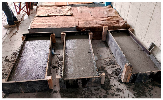
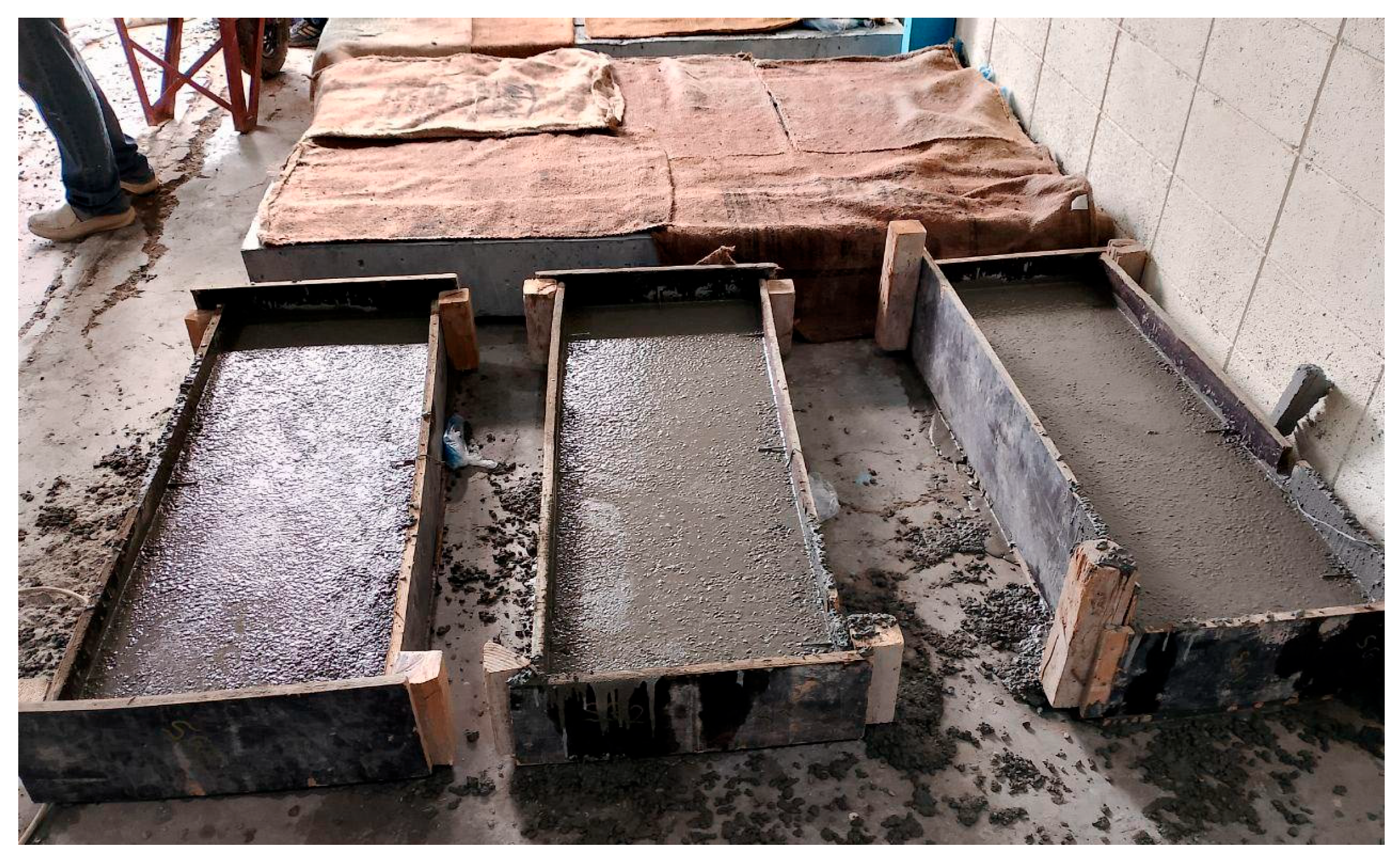
Figure 6 shows specimens with four bars. The leftmost one has closed curved bracket voids [()], the next has open curved bracket voids [)(], and the third one has conventional straight-line voids. The rightmost one is a solid reinforced specimen. Figure 7 shows the reinforcement cage with the wooden form. The bottom-left image shows the straight-line void configuration. The bottom-right image shows the closed bracket void shape of waste bottles. Figure 8 shows specimens with wooden forms after the concrete was cast inside the lab.
Figure 8.
Samples of voided one-way slabs.
The samples were treated in the usual way with water for 28 days (Figure 8).
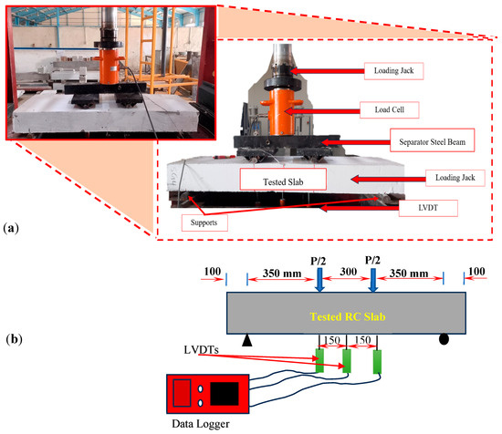
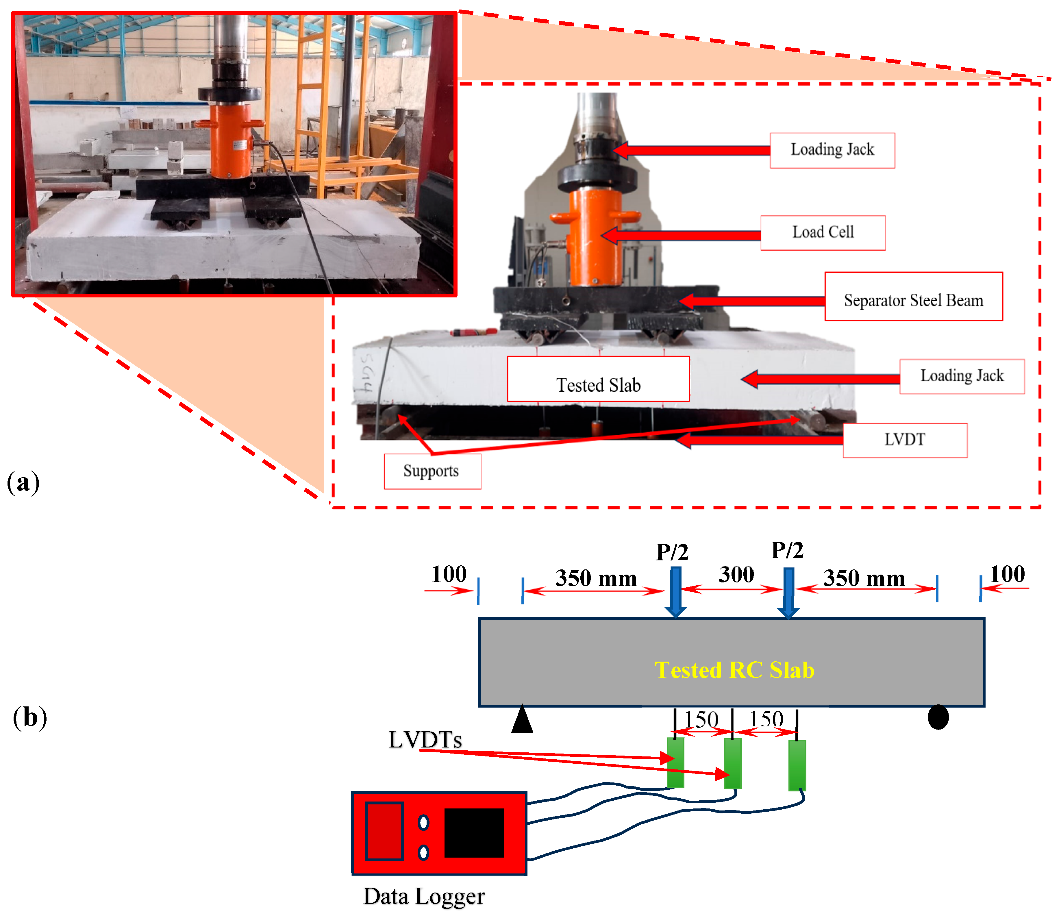
Flexural tests were conducted for all specimens. A 500 kN hydraulic jack was used to apply concentrated loads during four-point testing on the top side of the slab (Figure 9a). The load was applied monotonically using a hydraulic actuator at a controlled displacement rate of 0.3 kN/sec to accurately capture pre- and post-peak behavior. Three transducers were fixed at the soffit of the specimen and connected with the data logger to measure the profile deflection along the center line of the one-way slab. The deflection of the tested slab span, loading point, and support position was measured using LVDTs (Figure 9b). The load was applied gradually from zero until failure occurred. The first crack, crack width, and mode of failure were also recorded and observed during the test.
Figure 9.
Experimental setup of tested RC slab specimens: (a) Test rig, (b) schematic of the tested sample and LVDT locations.
3. Results and Discussion
All specimens were tested, and the collected results are presented in Table 2. The main parameters illustrated in Table 2 are for the cracking, inelastic (at 1000 ), and ultimate stages.
Table 2.
Results from the voided slabs.
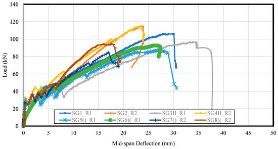
Table 2 shows that sample SG4II_R2 had a little more load resistance and failed at a slightly higher load of 115 kN as compared with the reference sample (114.5 kN). Meanwhile, specimen SG3II_R1 had more flexibility as its deflection value reached 34.53 mm.
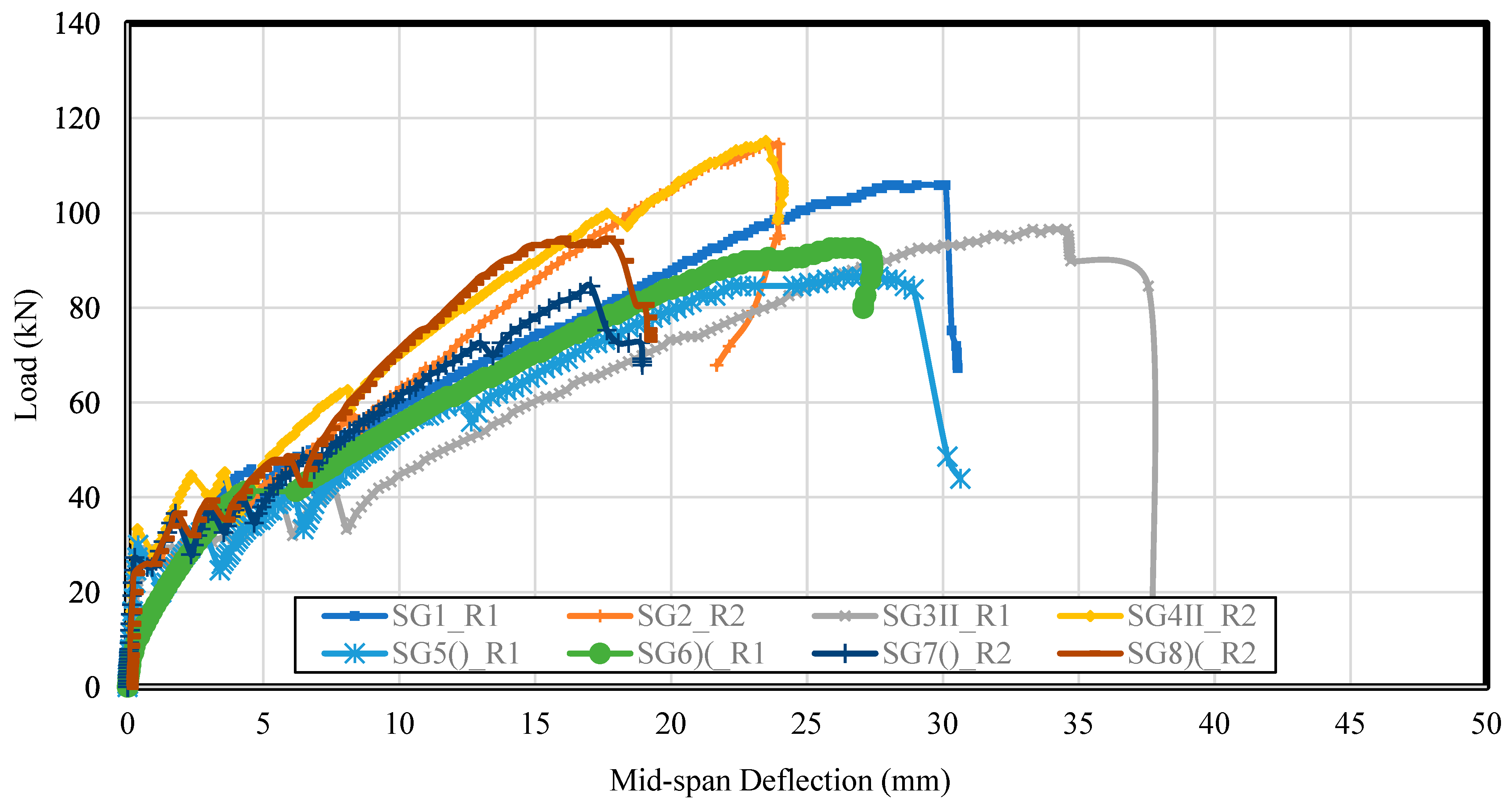
The load–deflection curves in Figure 10 illustrate the structural performance of all examined specimens under flexural loading. Initially, all specimens showcased a linear reaction, indicating elastic behavior before cracking occurred. As the load increased, variations in the peak load and deflection became obtrusive, reflecting the impact of variation in the reinforcement type or additional use of PET bottles encased in a wire frame. Specimen SG4II demonstrated the very best load potential and correct ductility, whilst SG6)(_R1 showed the best deflection, indicating superior energy absorption. Specimen SG6)(_R1 exhibited the largest deflection at all load levels. This is primarily because this particular void shape creates the most significant reduction in the effective concrete cross-section within the constant-moment region. The [)(] shape results in two voids placed close together near the mid-span, forming a narrow, hourglass-shaped concrete web. This significantly reduces the moment of inertia of the cracked section (Icr) as compared with the [II] or [)(] configuration. A lower moment of inertia directly translates to higher curvature and, consequently, larger deflection for a given applied moment, although the areas of all sections are the same. This has benefits regarding the anti-classical behavior’s effect on the strength of one-way RC slabs. In contrast, SG1_R1 and SG5()_R1 exhibited lower load capacities and more brittle behavior. Overall, the curves spotlight large variations in strength and ductility, emphasizing the effect of layout adjustments on the flexural performance of one-way reinforced concrete slabs. The enhanced deflection response is not solely due to weight reduction but also influenced by the optimized void geometry and reinforcement efficiency. On the other hand, the reduction in the effective moment of inertia (EI) due to void formation leads to a reduction in stiffness due to material removal, redistribution of stresses around the voids, and contribution by the reinforcement layout in maintaining structural integrity. Many studies have been conducted to test this hypothesis [7,11]; the recent tubular void configuration involved steel wire meshes that were thought to carry part of the tensile stress in the concrete section, especially when the section is cracked, as a result of nonlinear behavior after the cracking stage.
Figure 10.
The load–deflection relationships for all tested specimens.
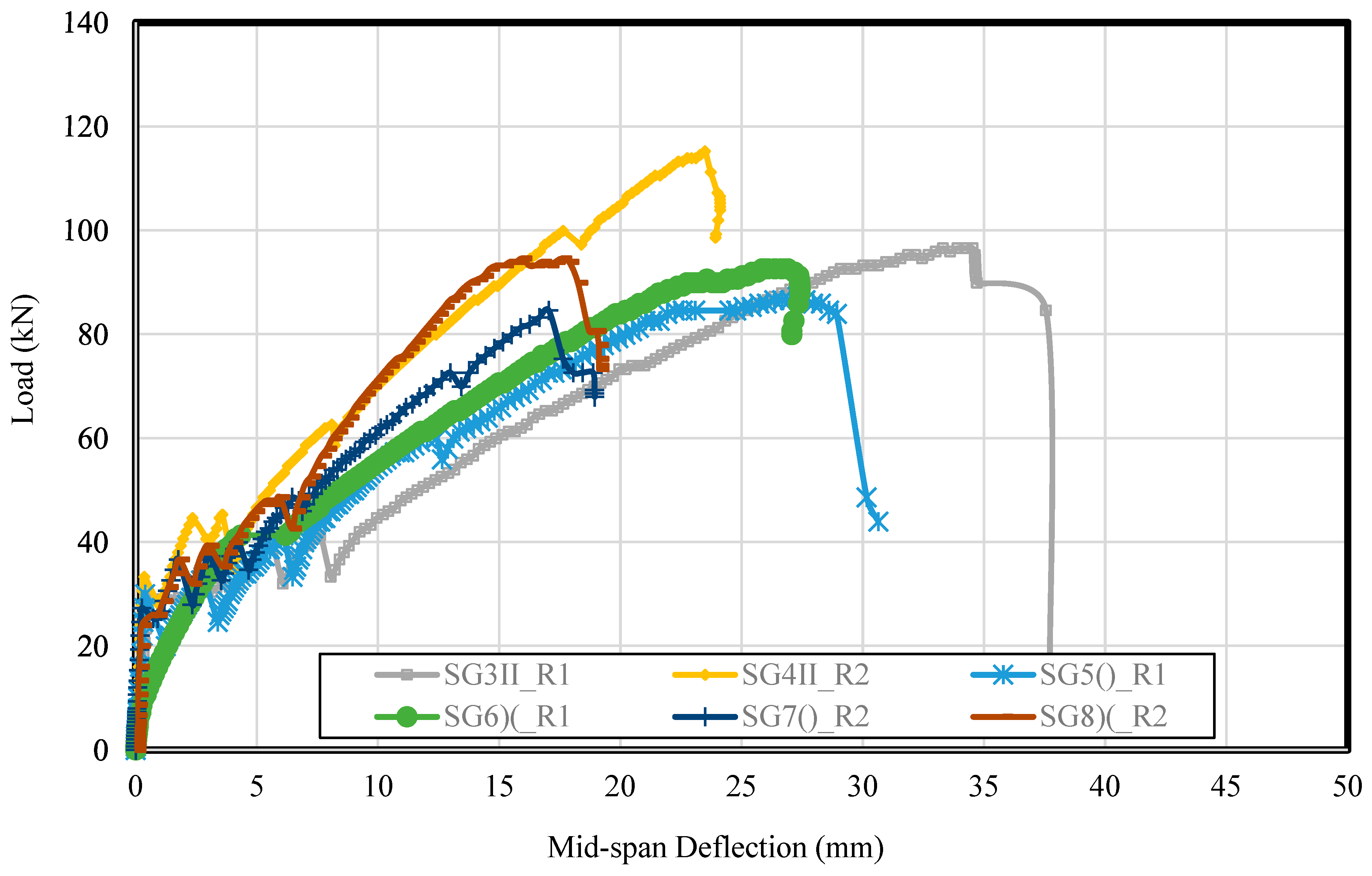
The load–deflection curves in Figure 11 represent the flexural behavior of hollowed (voided) reinforced concrete slab specimens under loading. All specimens showed a linear reaction to start with, indicating uncracked elastic behavior. Among the tested one-way slabs, SG4II_R2 achieved the highest peak load (approximately ~125 kN), reflecting strength likely due to the improved reinforcement or void configuration. SG3II_R1 exhibited the best mid-span deflection (~35 mm), indicating remarkable ductility and energy absorption notwithstanding a slight peak load. Specimens SG6()_R1 and SG3II_R1 additionally showed good overall performance in the elastic phase and their deformation capacity. In comparison, SG5()_R1 and SG8()_R2 showed reduced peak masses and showed greater, surprising post-peak drops, suggesting a brittle failure mechanism. The variation in responses from most of the voided specimens highlights the great impact of void geometry, void placement, and reinforcement on load-bearing potential and ductility. Overall, while voids reduce the specimens’ self-weight, proper design can preserve or maybe even improve structural performance.
Figure 11.
The load–deflection relationships of hollowed specimens.
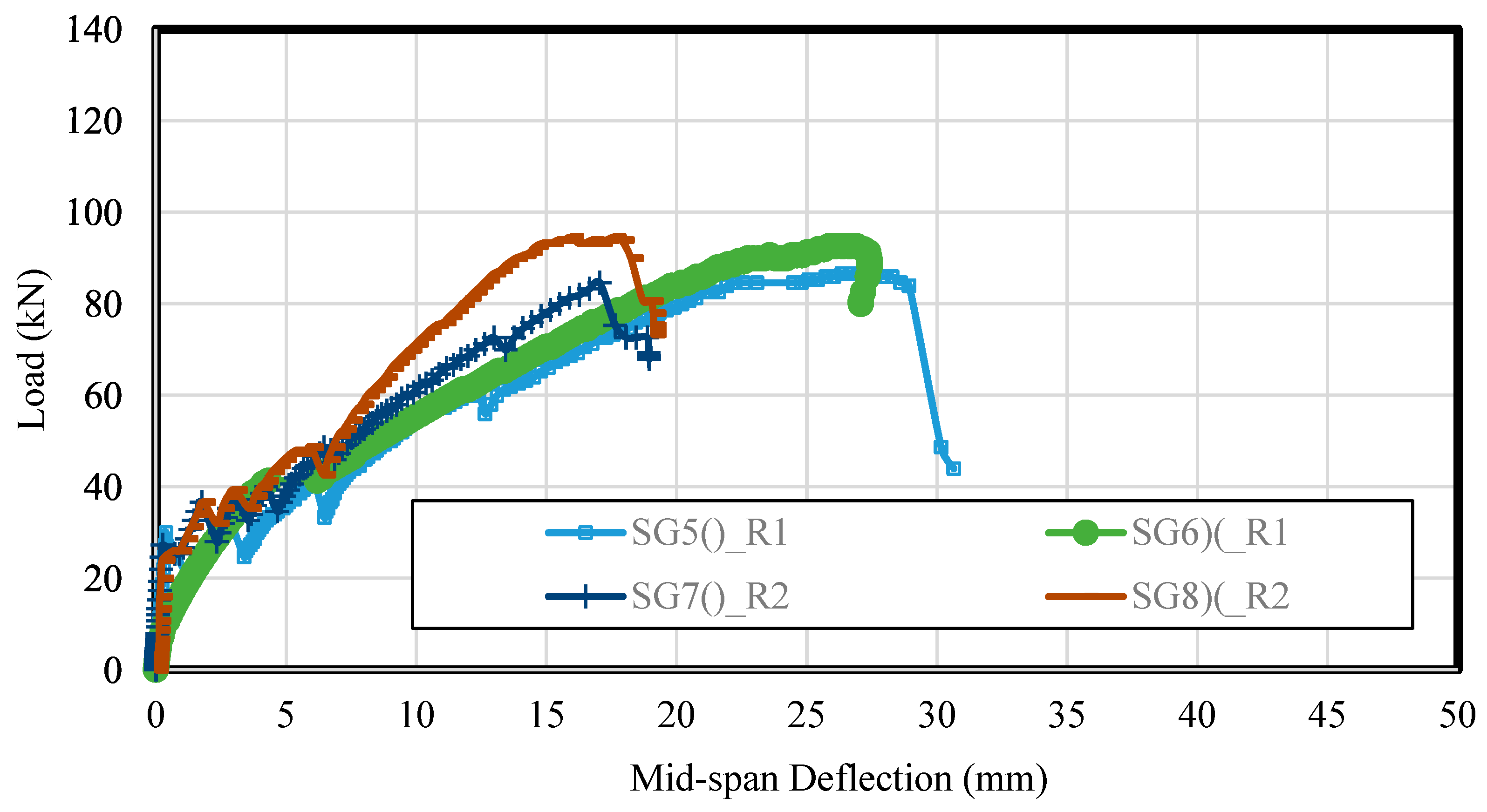
As a specific benefit of this new void placement technique, the deflection may be enhanced by more than 33% with voiding configuration [)(] as opposed to void configuration [()], as shown more precisely in Figure 12.
Figure 12.
The load–deflection relationships of optimal voided specimens.
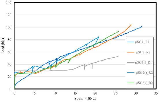
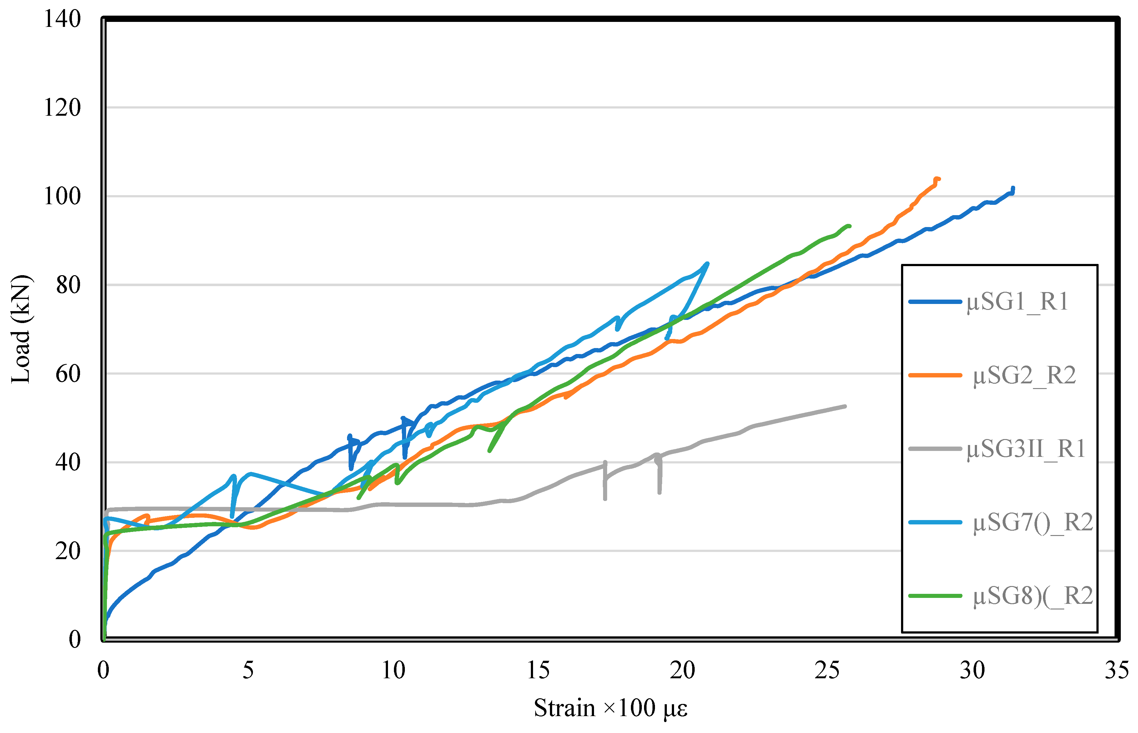
Figure 13 depicts the behavior of samples under different tested reinforcement strains and increasing load, highlighting their stiffness and material deformation properties. Originally, all samples showed a close linear relationship between stress and strain, indicating elastic behavior. Samples SG1_R1, SG2_R2, SG7()_R2, and SG8()_R2 showed relatively vertical slopes, suggesting high stiffness and efficient stress transfer to reinforcements. Among the samples, SG2_R2 and SG7()_R2 reached the highest strain values (~3100 µε), indicating better flexibility and ability to maintain high deformity before failure. On the other hand, µsg3ii showed reduced stress, reflecting poor performance; this is probably due to insufficient reinforcement or an unfavorable void configuration. SG1_R1 and SG7()_R1 showed some fluctuations, indicating the occurrence of cracks or macrostrains. Overall, the load ratio confirmed that the samples with better reinforcement or a better structural configuration (such as SG2_R2 and SG7()_R2) showed increased load resistance and flexibility, while others showed limited structural efficiency, such as SG3II_R1. It is important to note that the remaining samples could not be measured for strain because their strain gages did not work throughout the test stages.
Figure 13.
The load–strain relationships of some tested specimens.
Sample SG3II_R1 displayed resistance to loads as it did not crack quickly and had the highest load at its first crack (27 kN); SG1_R1 and SG5()_R1 displayed lower loads at first crack (21 kN). This explains that the reference model SG1_R1 was more brittle than the slabs with voids, because sample SG5()_R1 had lower deflection (0.29) than SG1_R1 (1.19) at its first crack (21 kN).
Sample SG8)(_R2 presented lesser deflection (17.58 mm) at a load of 94.57 kN—even less than that for the reference sample SG2_R2. That means that this type of void is more flexible. It can be seen that SG8)(_R2 had 17.58 mm deflection at a load of 94.57 kN, while the reference SG2_R2 with the same reinforcement had almost the same deflection (17.83) at a load of 97.37 kN.
In comparisons of the reference one-way slab SG1_R1 with the voided one-way slab SG5(), for the same load (21 kN) at first crack, SG5()_R1 displayed lesser deflection (0.9 mm) than SG1_R1 (1.19 mm). The same was observed with SG3II_R1 (0.62 mm). This means that the voided slab had greater deflection resistance than the slabs without voids. Even with different reinforcement, the same results were obtained. For the same load at first crack (24 kN), the sample SG2_R2 presented 0.4 mm deflection, while SG4II_R2 (0.22 mm), SG7()_R2 (0.17 mm), and SG8)(_R2 (0.25 mm) all had lesser deflection than the slabs without voids.
4. Sectional Analysis of New Hollow RC Beams
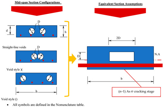
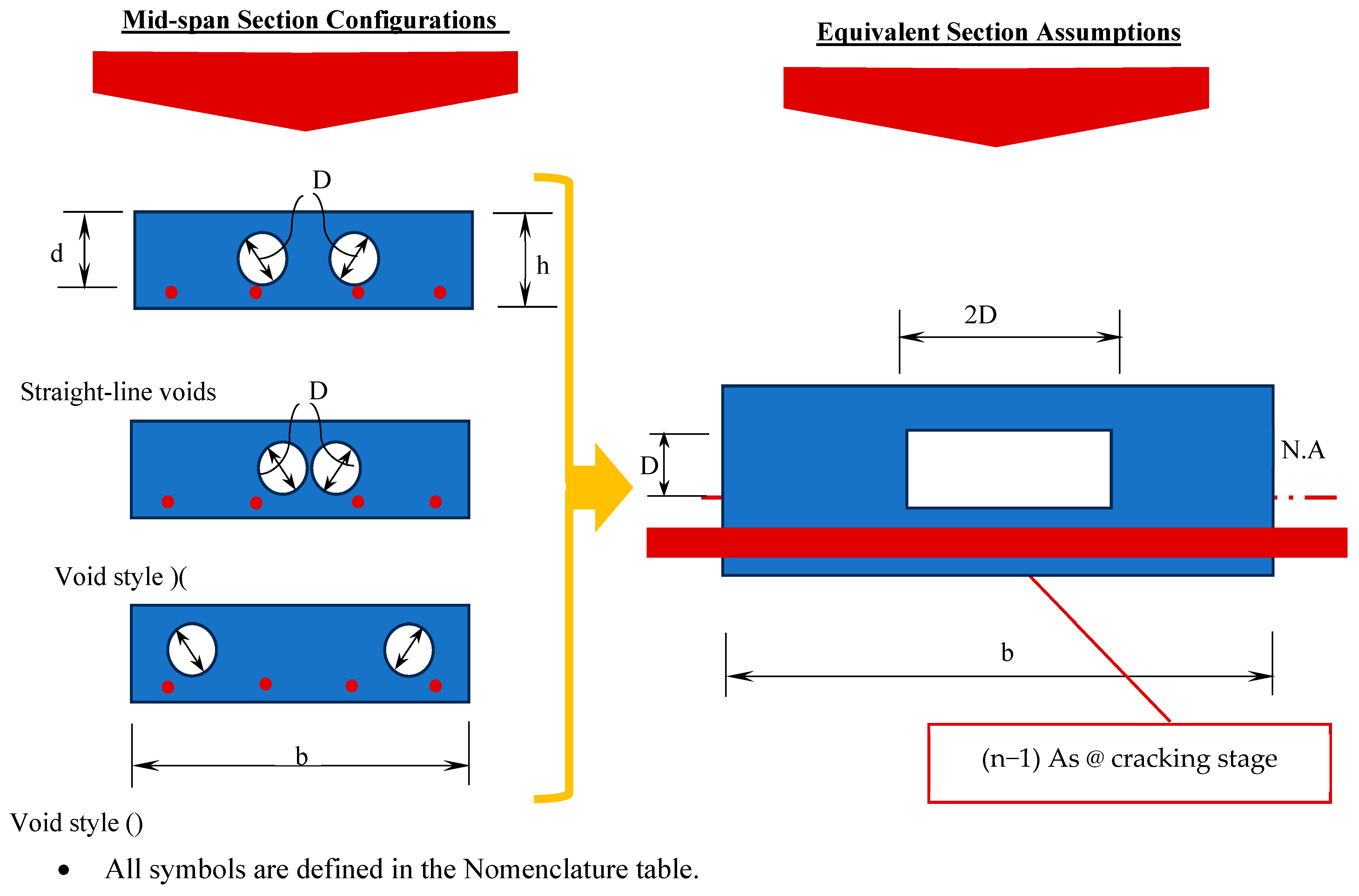
By using elastic theories and models, as well as the attributes of the transformed section, the flexural stress equation can be utilized to evaluate the first-crack load. The analytical model employs standard transformed section concepts, assuming plane sections remaining plane, perfect bonds between concrete and reinforcement, and linear elastic material behavior up to cracking. To account for the irregular void geometry, the cross-section is idealized by reducing the effective width of the compression zone in the region of the voids, as illustrated in Figure 14. As shown in Figure 14, the area of the hollow beam’s transformed section (At) is calculated as follows:
Figure 14.
Typical hollow RC one-way slabs: cross-section and transformed section.
Here, m is the modular ratio, m = Es/Ec; Es is the modulus of elasticity of the reinforcement (GFRP) bars (about 45 GPa); and Ec is the modulus of elasticity of concrete (can be estimated using the ACI 209 relation; Ec = 4700). Thus, the neutral axis depth can be computed as follows:
The moment of inertia of the uncracked section (Iucr) about the neutral axis is calculated as follows:
and the cracking capacity of the new voided beam can then be estimated as in [7]. However, in this study, the GFRP relation was used to predict the cracking moment:
where fr is the rupture modulus of the concrete mix used for casting specimens. The rupture modulus values tested in this study and used in Equation (4) are displayed in Table 3.
Table 3.
Experimental and theoretical cracking and ultimate load capacity of tested specimens.
Furthermore, to find the cracking load,
where is the distance from the load point location to the closest bearing support.
The cracking loads resulting from Equation (5) were compared with the experimental cracking loads provided in Table 4 for the eight specimens. The results of the analytical equation showed good agreement of the predicted values for all tested specimens. The average, standard deviation, and variance corresponding to the ratios (Pcr-Th/Pcr-Exp) for the cracking stage and (Pu-Th/Pu-Exp) for the ultimate stage across all tested specimens were obtained. These statistical values were used to evaluate the accuracy and consistency of the theoretical predictions compared with the experimental results. However, the coefficient of variance in all cases was not more than 0.01, and the standard deviation was not more than 0.10 of the tested hollowed beams.
Table 4.
Results for one-way voided slabs.
5. Deflection Profiles of Tested Specimens
The deflection profile of a hollow reinforced concrete (RC) one-way slab has famously precise traits in comparison to that of a solid slab because of the presence of voids or hole cores, which extensively affect the slab’s stiffness and weight distribution. The deflection profile of a hollowed RC one-way slab follows a parabolic or easy curvature, especially at the cracking and inelastic (ε = 0.001) stages, with most deflection occurring at the mid-span, much like what is observed for a solid slab. However, due to the reduced self-weight and less powerful stiffness as a result of the void sections, these slabs generally show greater deflection under the same loading conditions than their solid counterparts. The voids cause a reduction in the moment of inertia, which immediately impacts the flexural stiffness of the slab. The observations regarding some voided specimens, especially those with the back-to-back [)(] configuration, showed that they displayed deflections that were either similar to or slightly less than those of solid slabs under the same load. This can be explained by two key factors.
First, the cracking load for these voided slabs turned out to be higher than initially thought. This is probably due to the bundled bottles providing a sort of confinement that delayed the formation of cracks. Second, and perhaps more importantly, the stiffness after cracking is not just about the gross moment of inertia. The back-to-back [)(] shape seems to create a more efficient compression strut, which helps better distribute tensile stresses to the GFRP reinforcement. This effectively increases the cracked moment of inertia (Icr) as compared with simple straight voids.
Supporting this, an analysis of crack patterns revealed that the [)(] specimens had finer and more evenly distributed cracks. This indicated improved composite action and tension stiffening. Thus, while the gross inertia was reduced, the overall performance of these voided slabs was enhanced in significant ways.
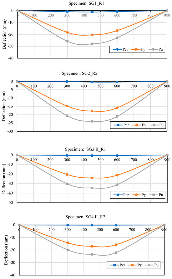
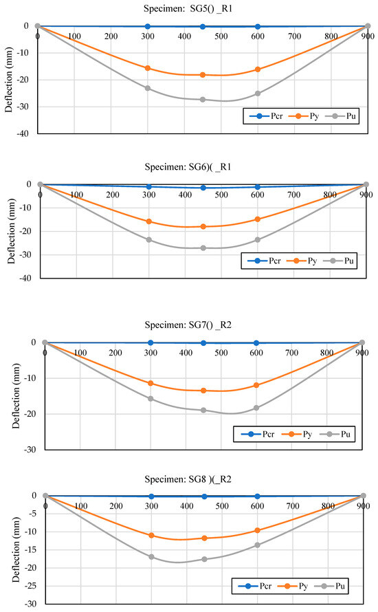
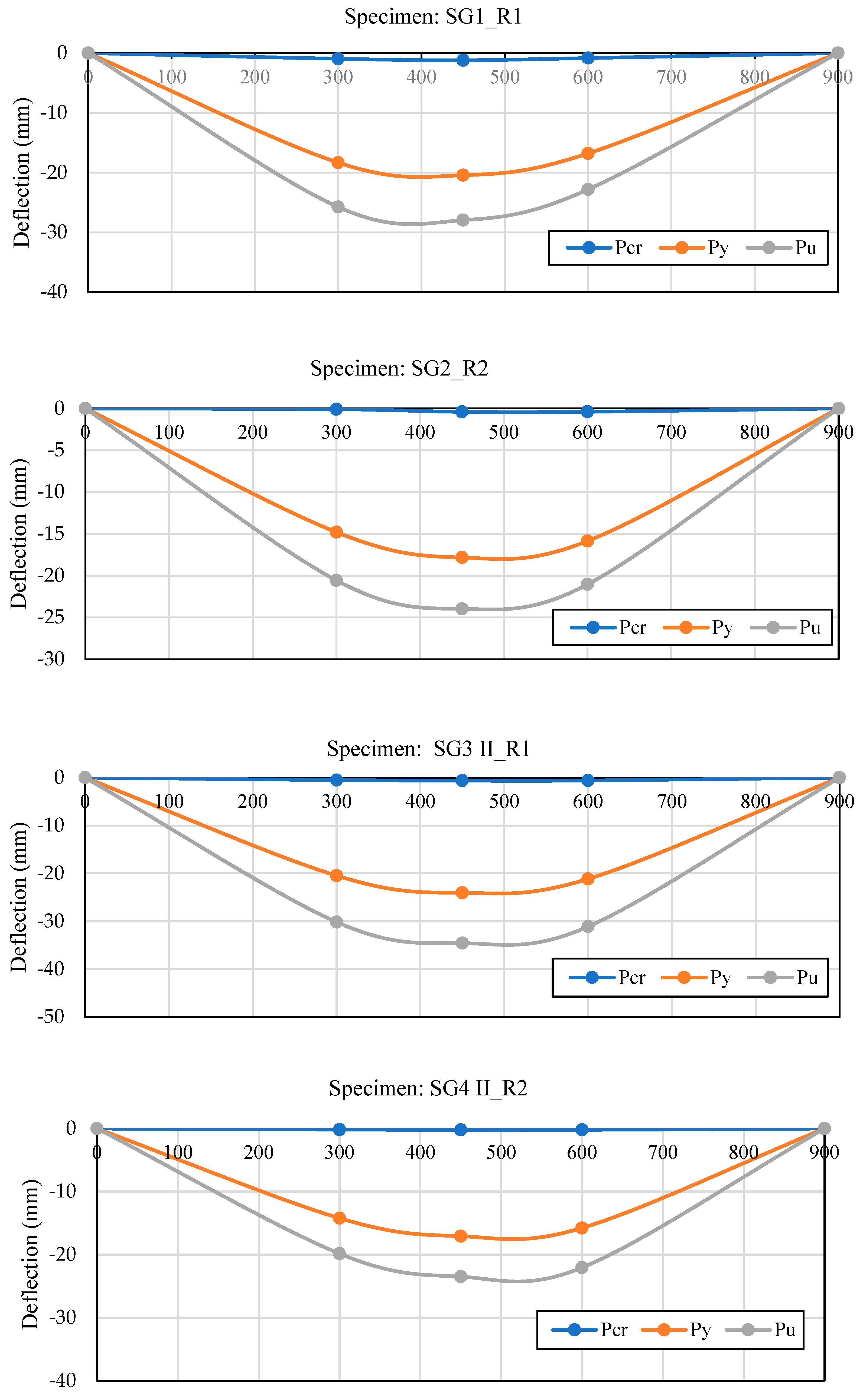
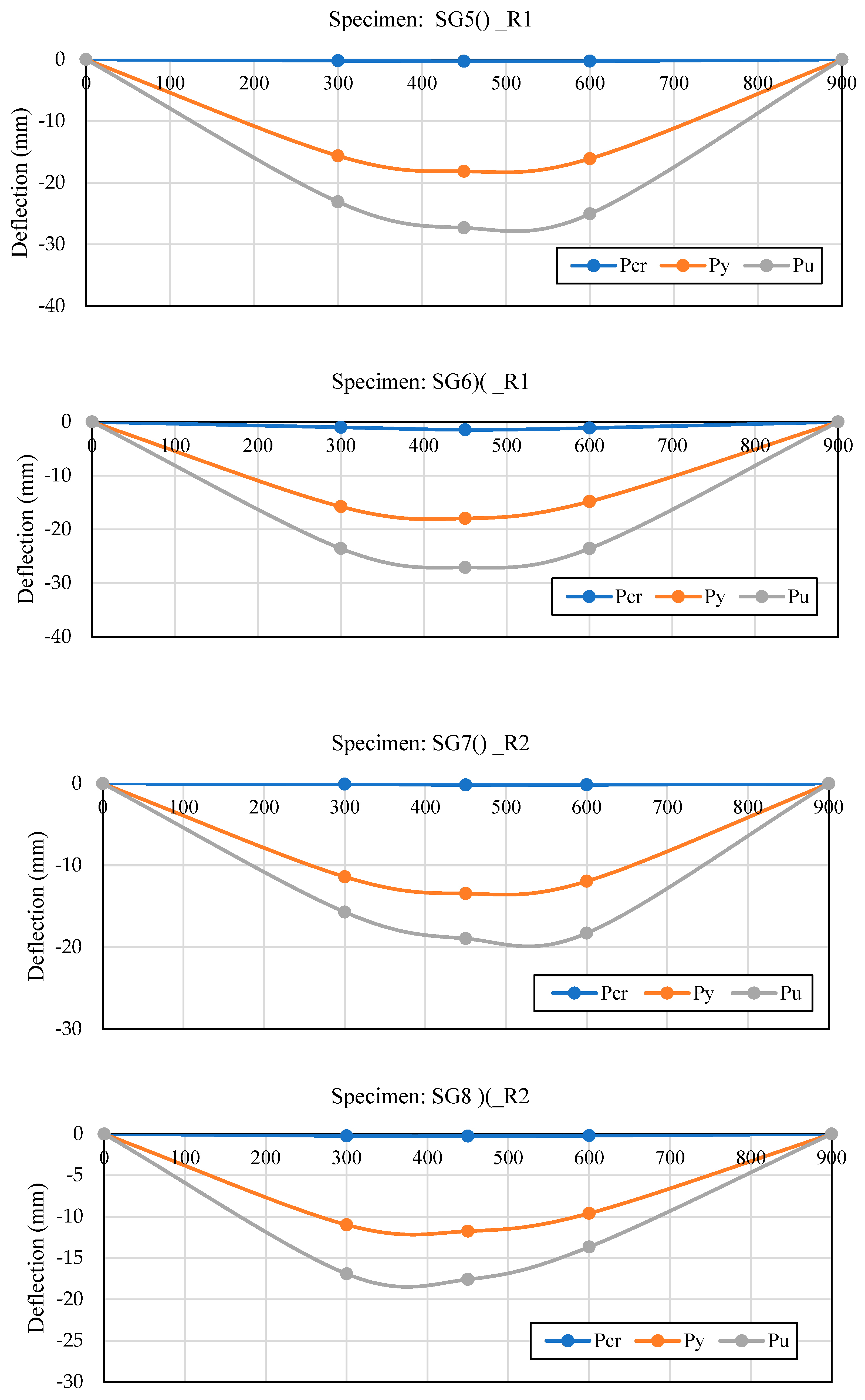
Despite this multiplied deflection, the layout of hollowed slabs normally guarantees that the deflections remain inside appropriate serviceability limits. Figure 15 shows the deflection profile of all tested specimens in three important stages: the cracking load (Pcr), inelastic deformation at equal strain (0.001) in GFRP reinforcements (Py), and the ultimate stage (Pu). The optimal void shape was the curved open-void configuration [)(] because it had the smallest deflection when compared with the reference solid RC slabs. This optimal configuration led to the best behavior in the cracking and inelastic deflection profiles.
Figure 15.
Profiles of deflections in one-way slab samples.
6. Failure and Cracking Modes of Tested Specimens
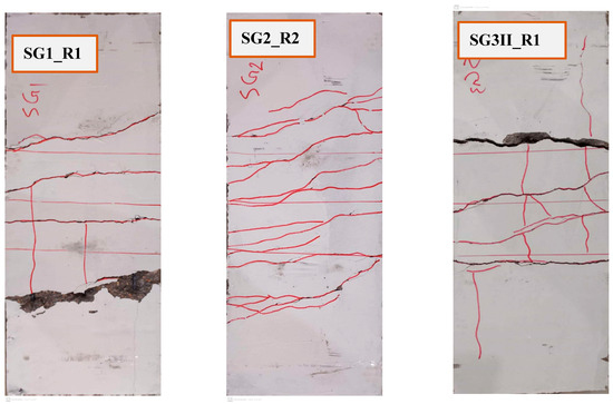
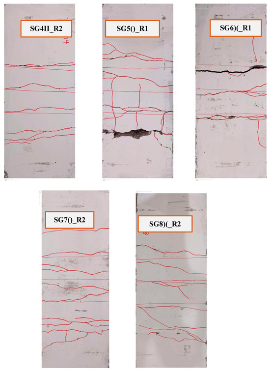
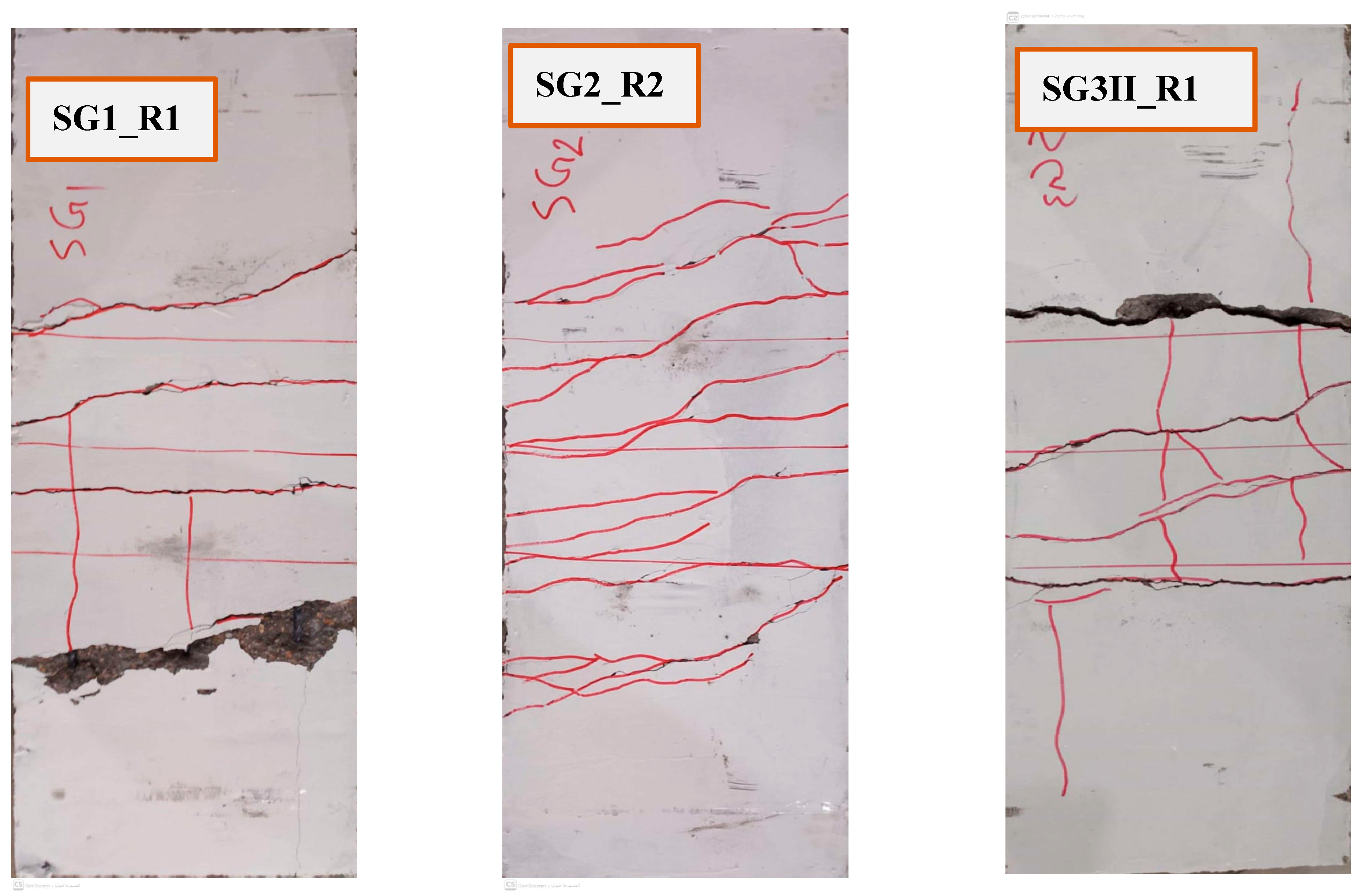
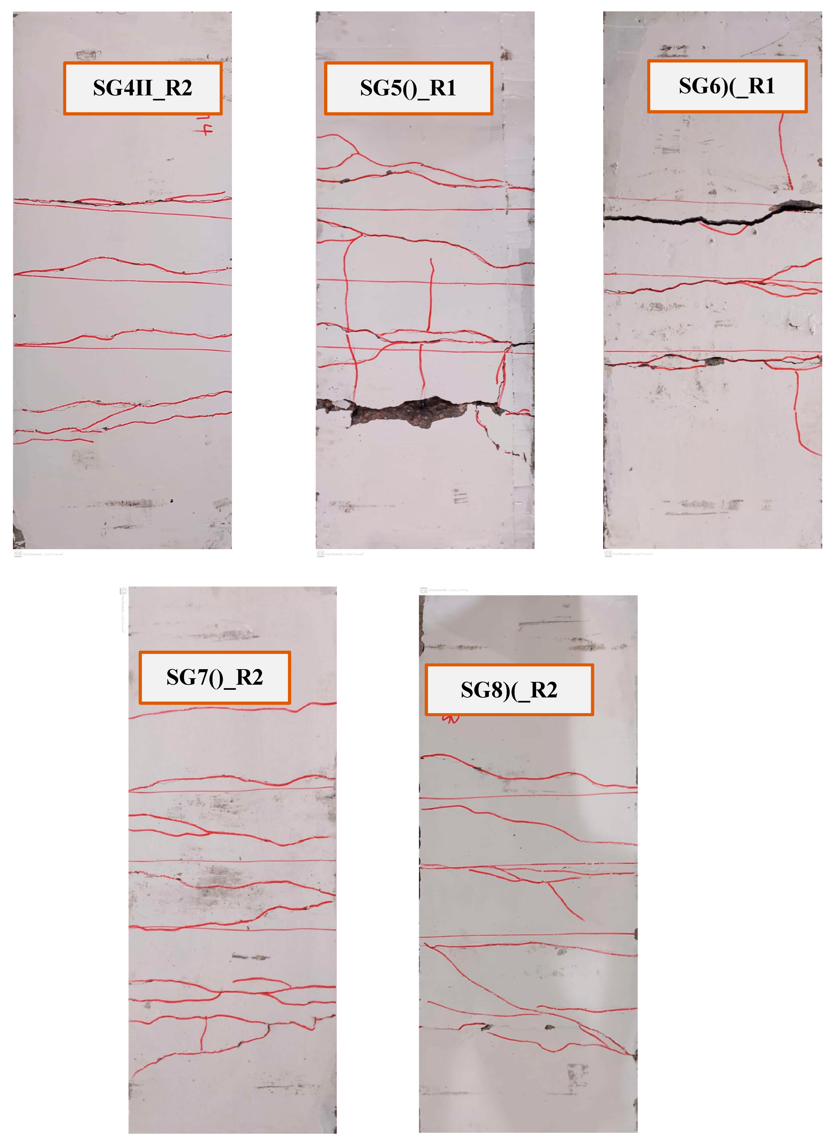
Figure 16 illustrates the crack patterns on the tested flexural specimens. In none of the studied samples did the top compression region in the mid-span become crushed. These cracks were typical flexural cracks, developing due to maximum bending moments at the mid-span. All cracks originated at the sample’s bottom face and spread along both sides of the one-way slabs. The primary cracks typically formed in a central area defined by the lines of load application, and all specimens showed ductile behavior compatible with flexural failure. The number of fractures appeared to differ according to whether the reinforcement was GFRP. While no dedicated instrumentation was used to measure slip, visual inspection of the slab halves after failure did not reveal any significant gaps or debonding at the concrete–PET bottle interface. This suggests that a good mechanical interlock was achieved, likely due to the rough surface texture of the bottles and the bundling technique. The bottles appeared to act monolithically with the surrounding concrete until cracking disrupted the section. The same was observed in previous experiments on intact PET bottles in many research studies, such as [7,11]. All specimens reinforced with three bars displayed larger crack widths. Furthermore, in the closed-bracket void configuration (i.e., [()]), a splitting crack was observed along the span of the bottom face, which may indicate the maximum bending region.
Figure 16.
Cracking configurations of the tested specimens.
7. Ductility, Toughness, and Stiffness
A reinforced concrete one-way slab’s ductility can be defined as its ability to withstand inelastic deformation without a reduction in load-carrying capacity before failure [12]. From Table 3, it can be seen that SG6)(_R1 had ductility of 1.51, greater than that of the reference (SG2_R2) although the same reinforcement was used. The ductility differed due to the large difference between the ultimate and inelastic stage deflection.
Toughness is the amount of energy absorbed during fracture and may be measured by calculating the area under the load–displacement curve. It is the effort spent per volume during material deformation [12]. Table 4 shows that SG7()_R2 had a toughness of 1063.34 kN·mm, less than that of reference SG2_R2 (1505.22 kN·mm) with the same reinforcement. The same was observed for SG5()_R1, with a toughness of 1931.43 kN·mm, in comparison with SG1_R1 (2261.3 kN·mm). With different voids, the corresponding results for SG6)(_R1 and SG8)(_R2 were 1713.10 and 1235.90 kN·mm, respectively, and those for SG1_R1 and SG2_R2 were 2261.3 and 1505.22 kN·mm, respectively.
Flexural stiffness is the product of the modulus of elasticity (E) and moment of inertia (I) of a one-way slab about its neutral axis. As the value of flexural stiffness increases, the strength of the slab to resist bending also increases [12].
8. Conclusions
The main outcomes of this study support the important usage of lighter hollowed RC one-way slab systems. The main conclusions are as follows:
- The use of a new method of bundling waste PET bottles to create voids resulted in self-weight reductions of 9% for straight voids or 10.3% for the curved scheme of back-to-back voids or front-to-front voids, as compared with the solid slab. This means that the curved void scheme increased the self-weight loss by about 30% when compared with the straight-line void configuration.
- The straight-line void configuration (II) achieved the highest ultimate load capacity, reaching 91% of the solid reference slab’s capacity if reinforced near the minimum reinforcement ratio and increasing to 101% if used with a 30% larger GFRP reinforcement ratio.
- The back-to-back curved configuration [)(] was identified as the most efficient design, providing a 10.3% reduction in self-weight while retaining 83% of the solid slab’s ultimate load capacity; in comparison, the front-to-front [()] configuration retained only 73%.
- The front-to-front curved void configuration exhibited the largest deflections, higher than those of the back-to-back void configuration at ultimate load, due to a more significant reduction in the cracked moment of inertia.
- The proposed analytical model predicted the ultimate moment capacity with reasonable accuracy, achieving a mean theoretical-to-experimental ratio of 1.01 with a standard deviation of 0.13 for the ultimate loading levels.
- The deflection profile of the new void configuration was less than that of the solid section of a one-way RC slab due to the decrease in self-weight of the member and increase in moment of inertia compared within the same sectional area.
- The ductility of the new curved void configuration was greater than that of the reference sample due to increased strain at the ultimate stages. Furthermore, stiffness increased at the first loading stage, and toughness otherwise decreased when the optimal void system was used. This was due to the decreased displacement increasing the strength in turn, along with enhanced strength from the self-weight reduction.
Author Contributions
A.S.M.: Conceptualization, Methodology, Validation, Formal Analysis, Writing—Original Draft, Investigation. H.S.Z.: Conceptualization, Methodology, Validation, Formal Analysis, Writing—Original Draft. Z.M.A.: Validation, Investigation, Data Curation, Software. O.Z.A.: Resources, Writing—Review and Editing, Supervision. All authors have read and agreed to the published version of the manuscript.
Funding
This research received no external funding.
Institutional Review Board Statement
Not applicable.
Informed Consent Statement
Not applicable.
Data Availability Statement
The authors confirm that all data underlying the findings are fully available without restriction. All relevant data are within the paper.
Conflicts of Interest
The authors have no conflicts of interest to declare.
Nomenclature
| Symbol | Description | Unit |
| At | Transformed cross-sectional area | mm2 |
| b | Width of slab section | mm |
| h | Total depth (thickness) of slab | mm |
| D | Diameter (or equivalent diameter) of void | mm |
| b′, h′ | Width and height of voided (removed) portion | mm |
| As | Area of tensile reinforcement | mm2 |
| As′ | Area of compression reinforcement | mm2 |
| d | Effective depth to tensile reinforcement | mm |
| d′ | Distance to compression reinforcement | mm |
| m | Modular ratio (Es/Ec) | — |
| Es | Modulus of elasticity of GFRP bars | GPa |
| Ec | Modulus of elasticity of concrete | MPa |
| fc′ | Compressive strength of concrete | MPa |
| C | Neutral axis depth | mm |
| Iucr | Moment of inertia of uncracked section | mm4 |
| Mcr | Cracking moment | kN·m |
| fr | Modulus of rupture of concrete | MPa |
| Distance from the load point to support (shear span) | mm |
References
- Lee, C.H.; Mansouri, I.; Kim, E.; Ryu, J.; Woo, W.T. Experimental analysis of one-way composite steel deck slabs voided by circular paper tubes: Shear strength and moment–shear interaction. Eng. Struct. 2019, 182, 227–240. [Google Scholar] [CrossRef] [Scilit]
- Sagadevan, R.; Rao, B.N. Flexural Behavior of Reinforced Concrete Biaxial Voided Square Slabs. ACI Struct. J. 2020, 117, 3–14. [Google Scholar] [CrossRef] [Scilit]
- Mohammed, M.S.; Ahmed, M.L.; Ali, Z.M.; Mahmoud, A.S. An Innovative Method of Voided Reinforced Concrete One-Way Slabs Using Bundled Waste PET Bottled Tubes. In Materials Science Forum MSF; Trans Tech Publications Ltd.: Wollerau, Switzerland, 2020; Volume 1007, pp. 76–84. [Google Scholar] [CrossRef] [Scilit]
- Dadzie, D.K.; Kaliluthin, A.K. Sustainability Performance of Voided Concrete Slab Using Waste Plastic Bottles. Civ. Eng. J. 2022, 8, 2490–2510. [Google Scholar] [CrossRef] [Scilit]
- Zayan, H.; Abdaljader, A.; Mawlood, I.; Mahmoud, A. State-of-Art of One- and Two-Way Voided Reinforced Concrete Slab. Iraqi J. Civ. Eng. 2024, 18, 118–130. [Google Scholar] [CrossRef] [Scilit]
- Chung, J.H.; Jung, H.S.; Choi, H.K. Flexural Strength and Stiffness of Donut-Type Voided Slab. Appl. Sci. 2022, 12, 5782. [Google Scholar] [CrossRef] [Scilit]
- Ali, Z.M.; Mahmoud, A.S.; Mohammed, M.S.; Ahmed, M.L. Structural behavior of voided reinforced concrete beams having a novel tact bundled waste plastic bottles. Innov. Infrastruct. Solut. 2023, 8, 237. [Google Scholar] [CrossRef] [Scilit]
- Hassan, R.F.; Nabeel, M.H.J.; Al-Salim, H.A. Influence of near surface fiber nets reinforcement on the behavior of solid and voided reinforced concrete beams. J. Eng. Appl. Sci. 2018, 13, 7612–7617. [Google Scholar] [CrossRef]
- Chung, J.H.; Choi, H.K.; Lee, S.C.; Choi, C.S. Shear capacity of biaxial hollow slab with donut type hollow sphere. Procedia Eng. 2011, 14, 2219–2222. [Google Scholar] [CrossRef] [Scilit]
- Fazaa Rajab, O.F.; Ali, Z.M.; Mahmoud, A.S.; Mohammed, M.S. Flexural Ductility, Stiffness, and Toughness of New Voided Reinforced Concrete One-Way Slab Using Waste Plastic Bottles. J. Eng. 2022, 2022, 8672694. [Google Scholar] [CrossRef] [Scilit]
- Brito, S.H.; Mahmoud, K.; El-Salakawy, E.F. Behavior of Reinforcing Bar Connection of Hollow-Core Slabs to Steel Beams under In-Plane Forces. CivilEng 2022, 3, 831–849. [Google Scholar] [CrossRef] [Scilit]
- Nouri, Y.; Ghanbari, M.A.; Fakharian, P. Flexural behavior of hybrid GFRP-steel reinforced concrete beam: Experimental and explainable artificial intelligence. Eng. Struct. 2025, 345, 121565. [Google Scholar] [CrossRef] [Scilit]
- Al-Badkubi, M.R.K.M. Finite Element Study on Ultimate Shear Capacity of Voided Reinforced Concrete Beams. In 2019 2nd International Conference on Engineering Technology and Its Applications, IICETA 2019; IEEE: New York, NY, USA, 2019. [Google Scholar] [CrossRef] [Scilit]
- Jiang, H.; Dong, X.; Fang, Z.; Xiao, J.; Chen, Y. Experimental Study on Shear Behavior of a UHPC Connection Between Adjacent Precast Prestressed Concrete Voided Beams. J. Bridge Eng. 2020, 25, 04020106. [Google Scholar] [CrossRef] [Scilit]
- Orientilize, M.; Rastandi, J.I.; Aries C, R.M.; Krisna Adi, S.S.; Abimantrana, A. Experimental Study of Hollow-core Slab Containing Waste PET Bottles. Makara J. Technol. 2021, 25, 48. [Google Scholar] [CrossRef] [Scilit]
- Al-Kabasi, A.A.; Al-Wardi, A.S.; Bux, Q.; Latif, I.; Ahmed, H. Numerical Simulation Study on Load Deflection and Strain Curve of UHPFRC Beams Under Static Load. Int. J. Adv. Sci. Technol. 2020, 29, 1360–1371. [Google Scholar]
- Megson, T.H.G. Structural and Stress Analysis; Butterworth-Heinemann: Oxford, UK, 2019; p. 20001996. [Google Scholar]
- Monti, G.; Napoli, A.; Realfonzo, R. Reliable design and optimization of SRP-, CFRP-, and GFRP-confined concrete: Experimental validation and cost-effectiveness analysis. Mater. Struct. 2025, 58, 350. [Google Scholar] [CrossRef] [Scilit]
- Dixon, D.E.; Prestrera, J.R.; Burg, G.R.; Chairman, S.A.; Abdun-Nur, E.A.; Barton, S.G.; Bell, L.W.; Blas, S.J., Jr.; Carrasquillo, R.L.; Carrasquillo, P.M. Standard Practice for Selecting Proportions for Normal, Heavyweight, and Mass Concrete (ACI 211.1-91); ACI: Farmington Hills, MI, USA, 1991. [Google Scholar]
- ACI Committee 318; Building Code Requirements for Structural Concrete (ACI 318-19) and Commentary. American Concrete Institute: Farmington Hills, MI, USA, 2019; 456p.
- Fu, H.; Zhang, J.; Wu, Z.; Chin, C.L.; Ma, C.K. Nonlinear analysis of axial-compressed corroded circular steel pipes reinforced by FRP-casing grouting. J. Constr. Steel Res. 2023, 201, 107689. [Google Scholar] [CrossRef] [Scilit]
- Fu, H.; Tian, J.; Chin, C.L.; Liu, H.; Yuan, J.; Tang, S.; Mai, R.; Wu, X. Axial compression behavior of GFRP-steel composite tube confined seawater sea-sand concrete intermediate long columns. Eng. Struct. 2025, 333, 120157. [Google Scholar] [CrossRef] [Scilit]
- Wang, M.; Wang, Y.; Zhang, X.; Chen, G. Bond behavior and bond strength model for ribbed FRP bar in FRP-confined concrete. Constr. Build. Mater. 2024, 449, 138318. [Google Scholar] [CrossRef] [Scilit]
- Zeng, J.J.; Liao, J.; Zhuge, Y.; Guo, Y.C.; Zhou, J.K.; Huang, Z.H.; Zhang, L. Bond behavior between GFRP bars and seawater sea-sand fiber-reinforced ultra-high strength concrete. Eng. Struct. 2022, 254, 113787. [Google Scholar] [CrossRef] [Scilit]
- Shallan, M.E.; Khalil, M.M.; Mahmoud, A.A.; El-Diasity, M.H. Shear performance of continuous deep beams reinforced with steel, GFRP bars, stirrups, and novel grating systems: An experimental study. Mater. Struct. 2025, 58, 231. [Google Scholar] [CrossRef] [Scilit]
- Ligarda-Samanez, C.A.; Huamán-Carrión, M.L.; Cabel-Moscoso, D.J.; Marlene Muñoz Sáenz, D.; Antonio Martinez Hernandez, J.; Garcia-Espinoza, A.J.; Fermín Calderón Huamaní, D.; Carrasco-Badajoz, C.; Pino Cordero, D.; Sucari-León, R.; et al. Technological Innovations in Sustainable Civil Engineering: Advanced Materials, Resilient Design, and Digital Tools. Sustainability 2025, 17, 8741. [Google Scholar] [CrossRef] [Scilit]
- Petrović, Ž.; Zorić, A.; Milošević, B.; Ranković, S.; Petronijević, P. Numerical and Experimental Study of Continuous Beams Made of Self-Compacting Concrete Strengthened by GFRP Materials. Eng 2026, 7, 37. [Google Scholar] [CrossRef] [Scilit]
- Yan, F.; Lin, Z.; Yang, M. Bond mechanism and bond strength of GFRP bars to concrete: A review. Compos. B Eng. 2016, 98, 56–69. [Google Scholar] [CrossRef] [Scilit]
- Saleh, N.; Ashour, A.; Lam, D.; Sheehan, T. Experimental investigation of bond behaviour of two common GFRP bar types in high—Strength concrete. Constr. Build. Mater. 2019, 201, 610–622. [Google Scholar] [CrossRef] [Scilit]
- Kumar, M.H.; Mohandoss, P. Effect of fibers and stirrup confinement on bond performance of spliced GFRP reinforced seawater concrete beams. Constr. Build. Mater. 2026, 509, 145053. [Google Scholar] [CrossRef] [Scilit]
- Elbawab, Y.; Elbawab, Y.; El Zoughby, Z.; ElKadi, O.; AbouZeid, M.; Sayed-Ahmed, E. Flexural Testing of Steel-, GFRP-, BFRP-, and Hybrid Reinforced Beams. Polymers 2025, 17, 2027. [Google Scholar] [CrossRef] [Scilit]
- Abu Sarhan, L.; Jrad, W. Assessing GFRP for sustainable concrete reinforcement in high-rise buildings. Front. Sustain. Cities 2025, 7, 1685718. [Google Scholar] [CrossRef] [Scilit]

Disclaimer/Publisher’s Note: The statements, opinions and data contained in all publications are solely those of the individual author(s) and contributor(s) and not of MDPI and/or the editor(s). MDPI and/or the editor(s) disclaim responsibility for any injury to people or property resulting from any ideas, methods, instructions or products referred to in the content. |
© 2026 by the authors. Licensee MDPI, Basel, Switzerland. This article is an open access article distributed under the terms and conditions of the Creative Commons Attribution (CC BY) license.