


Abstract
This study develops a progressive damage failure criterion to address limitations of traditional instantaneous strength criteria that cannot capture damage evolution or quantify accumulation mechanisms in coalbed methane (CBM) wellbore collapse analysis. A damage variable D defines four evolutionary stages—initiation, propagation, acceleration, and coalescence—coupled with stress redistribution and drilling fluid invasion effects to enable quantitative collapse period prediction. Three-dimensional numerical simulations using FLAC3D 7.0 (Itasca Consulting Group, Minneapolis, MN, USA) reveal that stress anisotropy controls directional damage initiation, while increasing the horizontal stress ratio K substantially reduces the safe collapse period and narrows the safe drilling fluid density window. Horizontal wells exhibit significantly higher collapse pressure requirements than vertical wells, providing a quantitative basis for trajectory optimization. Model predictions show good agreement with published experimental results, with maximum deviations of ≤10% for the collapse period and ≤9% for damage depth. Field applications demonstrated notably fewer wellbore stability incidents and improved drilling efficiency compared to conventional design approaches, validating the practical effectiveness of the proposed methodology for unconventional resource development.
1. Introduction
Coalbed Methane (CBM) is a crucial unconventional natural gas resource, making an important strategic contribution to the optimization of energy structure through its efficient exploration. Advanced drilling and completion technologies for CBM wells directly relate to the productivity and economic viability of each well [1]. However, coal’s unique reservoir characteristics—including low strength, high porosity, and well-developed natural fractures—create significant wellbore stability challenges that substantially inhibit drilling efficiency. Deep coal seam reservoirs, subjected to high in situ stresses, low permeability, and complex geological conditions, present particularly severe wellbore instability problems [2]. Field experience demonstrates that when CBM horizontal wells traverse coal seams with abundant structural weak planes, drilling fluid invasion accelerates hydration swelling and strength deterioration, significantly increasing wellbore collapse risk [3]. While various researchers have developed low-damage drilling fluid systems incorporating nano-material plugging agents to create effective sealing barriers [4], these approaches primarily optimize fluid properties without adequately addressing the fundamental mechanical processes and time-dependent evolution characteristics governing wellbore stability.
As CBM exploration advances into deeper formations, drilling technologies and well configurations continue to evolve [5,6]. Enhanced recovery techniques, such as hydraulic punching and fracturing, further complicate the wellbore stress environment [7]. Deep CBM wells experience complex interactions between stress redistribution, pore pressure changes, and coal matrix shrinkage during production, which collectively affect casing stability and integrity [8,9]. Mining-induced stress concentration can trigger substantial shear displacement around wellbores, as confirmed by field monitoring data [10,11]. Recent investigations into coal mass fragmentation and deformation behavior in high-stress environments [12] have enhanced understanding of progressive wellbore failure mechanisms in CBM reservoirs. Numerical modeling studies incorporating stress–pore pressure coupling have been conducted for horizontal CBM wells under underbalanced drilling conditions, considering coal shrinkage effects during gas desorption [13]. Experimental research on wellbores subjected to varying horizontal stress conditions reveals that stability duration depends critically on stress differential and stress ratio [14].
The influence of coupled physical processes on wellbore stability has attracted increasing attention. Interactions between stress redistribution, pore pressure variation, and chemical effects significantly impact collapse pressure predictions, with different failure criteria yielding markedly different results [15]. Research on shale gas wellbore instability has demonstrated that drilling fluid-induced strength degradation exhibits strong time-dependent characteristics, necessitating time-dependent models for collapse period prediction [16]. It is also worth noting that dynamic loading from drill-string vibrations can impose transient peak stresses that may accelerate damage initiation [17,18]; however, such dynamic effects are outside the scope of the present quasi-static analysis and are recommended for future integration with the progressive damage framework. Four broad categories of wellbore stability models can be distinguished in the literature. First, instantaneous strength criteria (e.g., Mohr–Coulomb, Drucker–Prager) predict collapse pressure at a fixed point in time but cannot capture the time-dependent progressive failure process from crack initiation to coalescence [15]. Second, time-dependent degradation models incorporate drilling fluid-induced strength reduction and have demonstrated that collapse period prediction requires explicit time-dependent formulations [16]; however, these models typically employ empirical degradation functions without a physically grounded damage variable. Third, coupled thermo-hydro-mechanical (THM) and poroelastic approaches [13,15] account for multi-field physical interactions but involve prohibitive computational costs for parametric engineering studies and do not quantify damage accumulation through distinct evolutionary stages. Fourth, coal-specific anisotropic formulations have incorporated bedding planes and cleat systems [2,14]; however, they predominantly rely on instantaneous failure criteria and lack a framework for predicting the time to collapse onset.
Despite these advances, three critical gaps persist in CBM wellbore stability analysis: (1) existing models cannot quantify the complete damage evolution process from initiation through propagation to coalescence using a physically calibrated damage variable DD D; (2) no framework has been established to predict collapse period as a function of time-dependent stress–damage–soaking coupling specifically for coal dual pore-fracture structures; (3) the directional dependence of damage accumulation under anisotropic stress fields has not been systematically quantified across multiple well trajectories and stress ratios.
To address these gaps, this study makes three specific contributions. First, a progressive damage failure criterion is established based on continuum damage mechanics theory, incorporating a physically calibrated damage variable DD D that defines four evolutionary stages (initiation, propagation, acceleration, and coalescence) with experimentally verified thresholds. Second, three-dimensional numerical simulations coupling stress redistribution, damage evolution, and drilling fluid soaking effects are conducted to quantitatively predict collapse periods across 12 representative working conditions. Third, a multi-condition stability evaluation framework is developed that provides quantitative guidance for drilling fluid density window design and well trajectory optimization in deep CBM reservoirs. The proposed approach advances beyond existing instantaneous strength criteria by enabling time-dependent collapse period prediction, and beyond existing THM models by providing a computationally efficient coal-specific damage framework applicable to parametric engineering studies.
2. Data and Methods
2.1. Mechanical Parameter Testing and Characterization of Coal Samples
Coal samples were obtained from deep coal seams at depths of 800–1200 m in a designated coalbed methane mining area. The samples were immediately waxed after collection to prevent dehydration and oxidation, then processed into standard cylindrical specimens (⌀50 mm × 100 mm) following International Society for Rock Mechanics (ISRM) specifications. Precision cutting and end-face grinding ensured parallelism within 0.02 mm to guarantee measurement accuracy.
Triaxial compression tests were conducted under confining pressures of 3, 6, and 9 MPa using an electro-hydraulic servo rock mechanics system (MTS815, MTS Systems Corporation, Eden Prairie, MN, USA), representing different burial depth conditions. A quasi-static strain rate of was maintained throughout testing to obtain complete stress–strain curves. The fundamental physical and mechanical properties derived from experimental measurements are summarized in Table 1, providing essential parameters for subsequent wellbore stability analysis.
Table 1.
Basic physical and mechanical parameters of coal samples.
Damage evolution parameters were inversely calibrated from the triaxial test data using the elastic modulus degradation method [25], following a four-step procedure to ensure reproducibility. Step 1 (Loading to target strain levels): Each specimen was loaded under displacement control at a quasi-static strain rate of to pre-defined strain levels corresponding to five characteristic points on the stress–strain curve: (i) linear elastic limit (), (ii) crack initiation threshold (), (iii) peak strength (), (iv) early post-peak (), and (v) residual strength plateau (). Step 2 (Unloading cycles): At each target strain level, the specimen was unloaded to 5% of the current axial stress at the same strain rate to prevent specimen disintegration while ensuring complete elastic recovery measurement. Step 3 (Secant modulus calculation): The secant elastic modulus at each unloading point was calculated as , where and represent the stress and strain ranges of the unloading segment, respectively. Step 4 (Damage variable quantification): The damage variable at each characteristic point was computed by substituting the secant modulus into the degradation relationship , where is the initial elastic modulus determined from the slope of the linear elastic segment. The relationship between the damage variable and the elastic modulus is thus expressed as:
A minimum of five unloading cycles per specimen and three replicate specimens per confining pressure condition were used to ensure statistical reliability of the calibrated parameters. The damage value was quantified at the characteristic points described above, covering the full range from crack initiation () through peak strength () to post-peak residual stages ().
The damage initiation stress threshold was determined by identifying the deviation point from linear elasticity in the stress–strain curve, corresponding to . The critical damage value was established based on the following physical criterion: at this damage level, the secant elastic modulus has degraded to , representing an 80% reduction from the intact modulus. This threshold corresponds to the post-peak stage on the stress–strain curve where macroscopic crack coalescence occurs and the coal mass loses its load-bearing capacity, consistent with the damage mechanics framework adopted by Wang et al. [25] for thermally damaged basalt under triaxial loading. The physical interpretation is further supported by acoustic emission monitoring during the triaxial tests, where a sharp increase in cumulative event counts was consistently observed as the damage variable approached 0.8, confirming the onset of macroscopic fracture network formation. These calibrated parameters form the foundation for implementing the progressive damage failure criterion in numerical simulations.
2.2. Theoretical Model of Wellbore Stress Field
Wellbore excavation during drilling operations disturbs the original three-dimensional in situ stress state in coal seams, inducing stress redistribution and concentration around the wellbore. A theoretical stress field model is established to quantify this redistribution as the foundation for subsequent stability analysis.
In this study, and denote the maximum and minimum horizontal principal stresses, respectively, which characterize the tectonic stress state of the coal seam formation at the target drilling depth. The stress ratio is introduced to characterize the degree of stress anisotropy, which governs the directional distribution of stress concentration around the wellbore. For vertical wellbores in an elastic medium, the stress distribution follows the Kirsch solution modified for three-dimensional conditions [26]. The radial stress , tangential stress , and axial stress at a distance from the wellbore center are expressed as:
where is the wellbore radius, is the drilling fluid pressure, is the angular position measured from the maximum horizontal stress direction, and is Poisson’s ratio. These equations reveal that tangential stress reaches maximum values at and 180° along the maximum horizontal stress direction, which are the critical locations for damage initiation.
Coal seams exhibit pronounced anisotropy due to bedding planes, face cleats, and butt cleats that form orthogonal fracture networks. These structural discontinuities influence both strength properties and stress distribution. For the present study, an equivalent continuum approach with averaged mechanical properties (Table 1) is adopted for the following physically justified reasons. First, the coal samples investigated in this study are retrieved from deep formations at 800–1200 m depth, where high confining pressures (3–9 MPa, as applied in the triaxial tests) progressively close natural fractures and bedding plane apertures, reducing the mechanical contrast between matrix and fracture networks and thereby diminishing the degree of effective anisotropy [27]. Second, field-scale stress redistribution around the wellbore is governed primarily by the far-field horizontal stress differential (characterized by ) rather than by local fracture-scale anisotropy, particularly when the anisotropy ratio of elastic moduli remains below 1.5, under which condition the equivalent isotropic approximation introduces errors of less than 10–11% in stress concentration predictions compared to fully anisotropic solutions [28]. Third, the equivalent continuum approach maintains computational feasibility for the parametric study across 12 working conditions, which would be prohibitively expensive with a discrete fracture network (DFN) representation. While this simplification may introduce conservative estimates for localized stress concentrations in strongly anisotropic coal seams, it adequately captures the dominant stress redistribution patterns governing wellbore stability at the formation scale.
For inclined and horizontal wells, coordinate transformation is applied to project the far-field stress components onto the wellbore-aligned coordinate system, resulting in modified stress distributions that depend on wellbore trajectory relative to principal stress orientations. This theoretical framework provides the analytical foundation for implementing the progressive damage criterion in three-dimensional numerical simulations.
2.3. Establishment of Progressive Damage Failure Criterion
Traditional instantaneous strength criteria cannot effectively characterize the progressive failure process from damage initiation to ultimate collapse in coal wellbores. This study establishes a progressive damage failure criterion based on continuum damage mechanics theory to quantify the damage accumulation mechanism.
A damage variable is introduced to represent the degree of material deterioration, ranging from 0 (intact state) to 1 (complete failure). The damage evolution equation is formulated based on the strain equivalence principle:
The selection of the Weibull and Kachanov damage evolution models is physically motivated by the two distinct degradation mechanisms operating simultaneously during CBM drilling operations. The Weibull distribution model (Equation (5)) is particularly suited to describe statistically distributed damage accumulation driven by time-dependent processes, wherein the shape parameter reflects the degree of material homogeneity: a lower value indicates greater heterogeneity in the spatial distribution of pre-existing defects within the coal matrix, while a higher value corresponds to a more uniform microstructure with concentrated damage initiation. In the context of CBM wellbore drilling, the Weibull model captures the stochastic nature of micro-crack nucleation and growth driven by drilling fluid invasion and chemical weakening of coal matrix bonds, where the variability in cleat spacing, pore size distribution, and mineral composition introduces inherent statistical scatter in the damage response. The scale parameter represents the characteristic time for damage progression under the combined action of soaking and mechanical loading.
The modified Kachanov damage model (Equation (6)), by contrast, describes deterministic stress-driven damage accumulation governed by a power-law dependence on the effective stress . Physically, this model corresponds to the progressive extension of pre-existing macro-cracks under sustained stress concentration at crack tips, where the damage exponent controls the sensitivity of the damage rate to stress level and the damage rate coefficient reflects the intrinsic resistance of the coal mass to stress-driven fracture propagation. This mechanism is dominant immediately following wellbore excavation, when stress redistribution induces high tangential stress concentrations at and 180° that drive rapid crack extension in the near-wellbore zone.
The decomposition of total damage rate into stress-induced, soaking-induced, and creep components in Equation (7) therefore provides a physically consistent representation of the two dominant degradation mechanisms operating during the critical drilling window: () captures the instantaneous mechanical response to stress redistribution upon wellbore excavation, governed by either the Weibull or Kachanov formulation depending on the prevailing stress state, while () captures the progressive time-dependent strength reduction induced by drilling fluid penetration into the coal matrix through the cleat network. The coupling between these two mechanisms is the physical basis for the nonlinear damage acceleration observed at D = 0.6–0.7, where stress concentration and soaking-induced weakening act synergistically to accelerate crack coalescence.
Two alternative damage evolution models are adopted:
(1) Weibull distribution model:
where is the shape parameter and is the scale parameter.
(2) Modified Kachanov damage model:
where is the damage rate coefficient, is the equivalent stress, and is the damage exponent.
To account for time-dependent degradation mechanisms during drilling operations, the total damage evolution rate is decomposed into three components representing distinct physical processes:
This decomposition represents the fundamental innovation of the present framework: unlike existing damage models that consider either stress-induced damage (Weibull or Kachanov) or soaking-induced damage in isolation, the coupled formulation in Equation (8) simultaneously captures the interaction between mechanical loading and drilling fluid invasion within a unified coal-specific damage variable, enabling quantitative prediction of the collapse period through four distinct evolutionary stages that cannot be characterized by instantaneous strength criteria. The additive decomposition of the total damage rate is adopted based on the principle of damage rate superposition, which is widely employed in continuum damage mechanics for multi-mechanism degradation processes and is analogous to the additive decomposition of strain rates in viscoplasticity theory [25]. While the three physical processes are not strictly independent—in particular, soaking-induced strength reduction amplifies the effective stress concentration and thereby accelerates stress-driven damage accumulation—this interaction is implicitly captured through the shared damage variable : as increases due to any mechanism, the degraded modulus and the reduced strength threshold feed back into the stress redistribution calculation at the next time step, producing the coupled nonlinear acceleration observed at = 0.6–0.7. The additive framework, therefore, does not assume strict process independence; rather, it decouples the rate contributions for computational tractability while preserving the essential coupling through the common state variable . This approach follows analogous multi-mechanism damage formulations in the rock mechanics literature for creep-fatigue interaction and thermo-mechanical damage [25].
Where
(1) Stress-induced damage follows the Weibull or Kachanov models described above, representing instantaneous damage accumulation under mechanical loading.
(2) Soaking-induced damage accounts for drilling fluid invasion and chemical weakening effects:
where is the soaking damage coefficient calibrated from long-term immersion tests, and is the characteristic time constant representing the penetration rate of drilling fluid into the coal matrix.
(3) Creep damage (simplified consideration): , where , , and are creep parameters. For the present analysis, focusing on relatively short drilling exposure periods (<48 h), creep damage is omitted from the numerical implementation based on the following quantitative justification. Creep behavior of coal under triaxial stress conditions follows a power-law time dependence of the form , where the creep rate decreases rapidly after the initial transient phase. Based on a preliminary sensitivity analysis conducted in this study, the cumulative creep damage contribution over 48 h at stress levels corresponding to near-wellbore conditions () accounts for approximately 3–5% of the total damage accumulation, while stress-induced and soaking-induced damage mechanisms contribute the remaining 95–97%. This indicates that the creep damage rate is at least one order of magnitude smaller than the combined stress and soaking damage rates during the critical drilling window. Furthermore, the sensitivity analysis was extended by incorporating the full three-component damage evolution equation (Equation (7)) with creep parameters calibrated from the triaxial test data and comparing the predicted collapse periods against the simplified two-component model. The results show that including the creep term modifies the predicted collapse period by less than 4.8% across all 12 simulated working conditions, which falls within the model validation error range of ≤12% established in Section 4.2. Therefore, the simplification of neglecting creep damage does not affect the primary conclusions of this study. It is acknowledged, however, that for extended drilling exposure periods exceeding 48 h or in deep high-temperature environments where creep rates are significantly elevated, the creep damage component should be explicitly incorporated into the progressive damage framework.
The dominant time-dependent mechanism is the coupling between stress-induced damage and drilling fluid soaking, which collectively control the collapse period prediction.
The damage evolution process is characterized by four distinct stages: initiation (), propagation (), acceleration (), and coalescence (). The critical damage threshold is defined as , at which point wellbore instability occurs. The damage initiation stress threshold corresponds to .
The damage parameters were calibrated through triaxial compression tests using the elastic modulus degradation method: , where the damage value at different strain stages was calculated from the unloading curve slopes. As shown in Table 2, the calibrated parameters vary with confining pressure conditions.
Table 2.
Calibrated damage evolution parameters under different confining pressures.
Regarding the selection between the two damage evolution models, both the Weibull and Kachanov formulations were implemented and compared in preliminary calculations. The Kachanov model (Equation (7)) was adopted as the primary formulation for the stress-induced damage component in all subsequent numerical simulations for the following reasons: (1) the Kachanov model directly relates the damage rate to the current equivalent stress at each computational point, making it physically transparent and numerically straightforward to implement within the FLAC3D stress update loop; (2) the equivalent stress is a natural output of the stress redistribution calculation at every time step, avoiding the need for additional time-tracking variables required by the Weibull formulation; (3) comparative calculations for three representative working conditions (vertical well = 1.2, = 1.5, and horizontal well = 2.0) showed that the two models yield collapse period predictions within 5% of each other when parameters are calibrated from the same triaxial test dataset (Table 2), confirming that model selection does not introduce significant uncertainty into the final results. The Weibull model (Equation (6)) is retained in Table 2 as an alternative parameterization that provides cross-validation and may be preferable for applications where time-dependent statistical damage (e.g., prolonged soaking beyond 48 h) is the dominant mechanism.
2.4. Numerical Simulation Model and Implementation
A three-dimensional numerical model was established using FLAC3D 7.0 software to quantitatively analyze wellbore stability in coalbed methane reservoirs. The constitutive framework and damage implementation are described as follows. The base constitutive model adopted is the standard Mohr–Coulomb elasto-plastic model, which is the built-in constitutive option in FLAC3D most appropriate for frictional geomaterials under triaxial stress states. The Ubiquitous-Joint model available in FLAC3D, which explicitly represents a single preferred plane of weakness, was considered but not adopted for two reasons: (1) the equivalent continuum approach with averaged mechanical properties (justified in Section 2.2) renders explicit weak-plane representation unnecessary for the target depth range of 800–1500 m; and (2) the Ubiquitous-Joint model introduces additional parameters (joint orientation, joint cohesion, joint friction angle) that cannot be independently calibrated from the available triaxial compression dataset. Progressive damage evolution is implemented through a user-defined damage updating subroutine written in FLAC3D’s built-in FISH programming language. At each time step , the subroutine performs the following operations: (i) retrieves the current equivalent stress and existing damage variable at each computational zone; (ii) computes the incremental damage using Equations (7) and (9); (iii) updates the damage variable , capped at to prevent numerical singularity; (iv) degrades the elastic modulus according to and passes the updated modulus back to the Mohr–Coulomb constitutive model for the next mechanical equilibrium iteration. This explicit damage–mechanics coupling ensures that stiffness degradation is continuously updated throughout the simulation, capturing the nonlinear feedback between damage accumulation and stress redistribution that governs progressive wellbore failure. Fine mesh discretization was employed in the near-wellbore region to accurately resolve the steep stress and damage gradients in this critical zone.
The numerical model adopts a cubic computational domain with the wellbore axis aligned along the z-direction. Model dimensions were set to 20 × 20 × 30 times the wellbore radius to ensure far-field boundary effects do not significantly influence the near-wellbore stress field. Eight-node hexahedral elements were utilized throughout the domain, with mesh refinement progressing from 0.1 times the wellbore radius at the wellbore wall to 2.0 times in the far-field region. The complete mesh comprises approximately 150,000 elements and 180,000 nodes, providing sufficient resolution for damage evolution analysis.
A mesh sensitivity analysis was conducted to validate the numerical model’s independence from mesh density. Three mesh configurations were tested: coarse mesh (80,000 elements), medium mesh (150,000 elements), and fine mesh (240,000 elements). The near-wellbore mesh sizes were adjusted proportionally while maintaining the same far-field dimensions. Critical output parameters, including collapse pressure and maximum damage depth, were compared across the three configurations, as presented in Table 3. The results demonstrate that variations in collapse pressure and damage depth remain within 5% when transitioning from medium to fine mesh, indicating adequate convergence. Specifically, the collapse pressure varies by only 3.2% and the damage depth by 4.1% between medium and fine meshes. Considering the trade-off between computational accuracy and efficiency, the medium mesh configuration (150,000 elements) was adopted for all subsequent simulations, providing reliable predictions with reasonable computational cost.
Table 3.
Mesh sensitivity analysis results.
The three mesh configurations are illustrated in Figure 1, which presents cross-sectional views of the near-wellbore mesh discretization for the coarse, medium, and fine configurations. The mesh is structured with concentric zones of progressively increasing element size from the wellbore wall outward, transitioning from the minimum element size (0.1 for all configurations) at the wellbore boundary to the maximum far-field element size (2.0) at the model boundary. The near-wellbore refinement zone, extending to approximately 3 from the wellbore center, contains the highest mesh density to accurately resolve the steep stress and damage gradients in this critical region. Beyond this zone, element sizes increase gradually following a geometric progression with a growth ratio of 1.2 to minimize computational cost while maintaining solution accuracy in the far field.
Figure 1.
Mesh discretization configurations for the three-dimensional FLAC3D numerical model: (a) coarse mesh (80,000 elements), (b) medium mesh (150,000 elements), and (c) fine mesh (240,000 elements). Cross-sectional views at the wellbore mid-depth plane ( = 1000 m) show the near-wellbore refinement zone extending to from the wellbore center. Element sizes transition from at the wellbore wall to in the far-field region.
In addition to the spatial mesh sensitivity analysis presented in Table 3, a time-step sensitivity analysis was conducted to verify the convergence of collapse period predictions with respect to the temporal discretization. Three time-step sizes were tested for a representative base case (vertical well, depth = 1000 m, stress ratio = 1.5, mud density = 1.35 g/cm3): = 0.05 h (fine), = 0.1 h (standard, adopted for all simulations), and = 0.2 h (coarse). The predicted collapse periods and maximum damage depths at = 50 h are compared in Table 4. The results demonstrate that the standard time step of = 0.1 h produces predictions within 1.3% of the fine time-step solution, confirming temporal convergence. The coarse time step of = 0.2 h introduces errors of up to 3.8%, which remains within acceptable engineering tolerance but is less conservative than the standard step. Considering the balance between computational efficiency and accuracy, = 0.1 h with adaptive reduction (described in Section 2.4) was adopted as the standard time step for all subsequent simulations.
Table 4.
Time-step sensitivity analysis results for the base case (vertical well, depth = 1000 m, = 1.5, = 1.35 g/cm3).
The top boundary applies vertical stress corresponding to overburden weight, where is rock density, is gravitational acceleration, and is depth. The bottom boundary is fixed to prevent rigid body motion. Lateral boundaries impose horizontal principal stresses and representing tectonic stress fields. The wellbore wall boundary applies drilling fluid pressure
where is mud density.
The simulation implements stress–pore pressure coupling based on Biot’s effective stress principle [29]. In the present implementation, the pore pressure field is prescribed at the wellbore boundary as a function of drilling fluid invasion depth and soaking time, while the mechanical stress field responds through the effective stress relationship (Equation (11)). This constitutes a one-way-dominant coupling, distinct from a fully bidirectional poroelastic formulation: pore pressure drives effective stress redistribution as the primary coupling direction, while the reverse coupling (pore pressure response to solid skeleton deformation) is approximated through time-dependent boundary condition updates rather than a fully resolved fluid transport equation. This distinction is reflected in Table 5, where the coupling scheme is labeled accordingly. While a complete poroelastic formulation with explicit fluid flow governing equations would provide higher fidelity, the present one-way-dominant approach is consistent with standard practice in FLAC3D geomechanical modeling for wellbore stability analysis and is adequate for capturing the primary stress–pore pressure interaction governing collapse period prediction.
where is the effective stress tensor, is the total stress tensor, is the Biot coefficient, is pore pressure, and is the Kronecker delta. The time-dependent analysis employs an adaptive time step of h to balance computational efficiency and accuracy in capturing damage evolution. Several measures were implemented to ensure numerical stability throughout the simulation. First, the adaptive time stepping scheme automatically reduces by 50% when the incremental damage variable exceeds within a single time step, preventing abrupt stiffness degradation that would otherwise cause numerical divergence during the acceleration and coalescence stages ( and , respectively). Second, strict convergence criteria are enforced at every time step as summarized in Table 5: force equilibrium convergence requires residual values below , and displacement convergence demands incremental changes less than m, with a maximum of 500 iterations permitted per step. If convergence is not achieved within 500 iterations, the time step is automatically halved and the step is restarted. Third, FLAC3D’s built-in local damping with a damping coefficient of 0.8 is applied to dissipate spurious numerical oscillations that may arise during rapid stiffness transitions associated with progressive damage evolution, particularly in elements transitioning from the propagation stage to the acceleration stage. These combined measures ensured that all 12 simulated working conditions achieved stable convergence throughout the full damage evolution process from initiation to coalescence, with no instances of numerical divergence observed.
Table 5.
Numerical simulation parameter settings.
Convergence criteria were strictly enforced to ensure solution reliability. Force equilibrium convergence requires residual values below , displacement convergence demands incremental changes less than m, and a maximum of 500 iterations per time step prevents excessive computational cost. The complete numerical simulation parameter settings are summarized in Table 5.
As shown in Table 5, the comprehensive parameter configuration ensures both computational accuracy and efficiency for progressive damage analysis in coalbed methane wellbore stability evaluation.
3. Results
3.1. Mechanical Properties of Coal and Wellbore Stress Distribution
As shown in Figure 2, the experimental results obtained through triaxial compression tests identify that deep coal has strong strength improvement and complex deformation and failure behaviors under confining pressure conditions. Figure 2a presents the smoothed stress–strain curves obtained from triaxial compression tests. The curves were fitted using polynomial regression to highlight the overall trends, while maintaining the key characteristic points (peak strength, residual strength) from raw experimental data. When the confining pressure increases from 3 MPa to 9 MPa, the maximum strength of the coal specimens grows from 22.4 MPa to 35.8 MPa, increasing by 59.8%. This indicates that confining pressure has an effective closing action on the microcracks inside the coal mass, along with the improvement action for the bearing strength. The characteristics of the stress–strain relations include the elasticity stage, yield stage, and softening stage after peak. The modulus has a nonlinear growth process along with the improvement in confining pressure, illustrating that the dynamic evolving process for the pore structure inside the coal mass meets the requirements during the loading process. The rate of strength drop during the softening stage has a notable connection to confining pressure. If the confining pressure is low, then the coal has distinctive brittle failure properties, whereas increasing the confining pressure can improve the properties toward ductile failure types. The difference in the mechanical properties can provide an experimentally verified explanation for the wellbore instability phenomenon under different burial depth conditions.
Figure 2.
Triaxial compression mechanical properties and wellbore stress distribution of coal.
The distribution characteristics of wellbore stresses obtained from the numerical simulation calculation results explicitly display the disturbance caused by drilling, leading to the redistribution of the stress concentration. The radial distribution in Figure 2b clearly illustrates a gradual distribution from the wellbore wall to the interior, reducing the radial stress on the wellbore wall to the pressure level of the drilling fluid, forming a transition zone approximately 0.5–1.0 times the wellbore radius from the wellbore wall. However, the tangential stress distribution around the wellbore displays marked circumferential asymmetry, the physical origin of which can be explained as follows. The asymmetric distribution arises fundamentally from the difference between the maximum and minimum horizontal principal stresses (characterized by ), whose directional dependence is governed by the term in the Kirsch solution (Equation (2)). At the maximum horizontal principal stress directions ( and 180°), the two stress components and act in the same additive sense at the wellbore wall (), producing a stress superposition effect that drives tangential stress to its maximum value of 86.3 MPa. Conversely, at the minimum horizontal principal stress directions ( and 270°), the term becomes negative, reversing the sign of the second component and producing a stress relief effect that reduces tangential stress to its minimum value of 34.7 MPa. The resulting stress concentration factor reaches 2.49 () between these two principal directions, directly controlling the preferential locations for damage initiation. Furthermore, this circumferential asymmetry intensifies with increasing value: as increases from 1.2 to 2.0, the stress differential between and directions increases from 17.2 MPa to 51.6 MPa (as discussed in Section 4.1), progressively concentrating damage risk in the maximum horizontal stress azimuth. This mechanistic understanding explains the bimodal damage pattern observed in Figure 3, where damage preferentially initiates and propagates along the and 180° directions. This marked difference directly affects the location determination of wellbore zones that tend to become unstable. The distribution pattern marked in Figure 2d clearly shows continuous wellbore distribution characteristics for the stress variation. The tangential stress takes on maximum values at angles θ = 0° and 180°, denoting a bimodal distribution pattern, while the radial stress keeps a stable level. The calculated concentration factors demonstrate that, under strong differential stresses, local tangential stresses could reach 3–4 times the uniaxial compressive strength of the coal.
Figure 3.
Spatial-temporal distribution characteristics of progressive wellbore damage evolution under identical stress conditions (vertical well, depth = 1000 m, stress ratio = 1.5, mud density = 1.35 g/cm3, drilling fluid soaking coefficient = 0.012 h−1). The four panels represent damage field snapshots at successive time steps corresponding to the four defined damage stages: (a) damage initiation stage (t = 5 h), showing localized damage concentrated along the maximum horizontal stress direction (θ = 0° and 180°) with damage depth 0.2–0.5 rw; (b) damage propagation stage (t = 15 h), showing lateral extension of the damage zone to 0.8–1.2 rw under continued soaking-induced strength degradation; (c) damage acceleration stage (t = 30 h), showing rapid crack coalescence and pronounced circumferential asymmetry as damage depth reaches 1.2–1.5 rw; (d) damage coalescence stage (t = 50 h), showing complete fracture network formation and loss of load-bearing capacity as damage depth exceeds the critical threshold of 1.5 rw, triggering wellbore collapse. Stage D-value definitions follow Section 2.3. All panels share the same damage variable color scale ( = 0–1) shown on the right.
3.2. Wellbore Damage Evolution Process
Although the numerical model is fully three-dimensional (as described in Section 2.4), horizontal cross-sections at mid-depth (Z = 1000 m) are presented in Figure 3 to clearly visualize the circumferential damage distribution pattern around the wellbore, which is the primary concern for stability assessment.
Numerical simulation results indicate that there is a comprehensive process for progressive damage evolution in the coal wellbore, subjected to the invasion and stress concentration effects simultaneously. Referring to Figure 3, it can be found that each stage has its regional characteristics, where the difference in the range and spreading way for damage variable D is apparent. The initiation stage (D-value ranges as defined in Section 2.3), illustrated by Figure 3a, concentrates around the maximum horizontal principal stress direction, with damage depth ranging from 0.2 to 0.5 times the wellbore radius. Driven by continuous soaking, coal strength weakens progressively, extending damage outward into the propagation stage, illustrated by Figure 3b, where damage depth increases to 0.8–1.2 times the wellbore radius. Although complete failure has not yet occurred, bearing strength has sharply decreased at this point. With continued weakening, the acceleration stage follows (Figure 3c), characterized by rapid crack propagation and coalescence forming spalling failure paths, during which the unstable wellbore zone loses strength substantially. Subsequently, in the coalescence stage (Figure 3d), multiple fracture networks merge completely, forming discontinuous regions that trigger wellbore collapse and complete loss of load-bearing capacity.
The damage depth range of 0.2–0.5 times the wellbore radius observed during the initiation stage is consistent with damage zone extents reported in the existing literature for coal seam wellbores under comparable geological conditions. Liu et al. [2] reported numerically simulated damage depths of 0.3–0.6 times the wellbore radius for coal seam wellbores under lateral stress ratios of at depths of 800–1200 m, which encompasses the initiation-stage range observed in the present study. Experimental measurements on horizontal coal seam wellbore specimens subjected to lateral stress differentials equivalent to K = 1.5–2.0 reported damage zone extents of 0.25–0.55 times the wellbore radius, providing direct experimental corroboration for the initiation-stage damage depths predicted by the present model. The progressive expansion of damage depth from 0.2 to 0.5 at initiation to 1.8 at the coalescence stage is also physically consistent with the damage accumulation sequence documented by Zhang et al. [12], who observed that blast-induced damage zones in deep coal under high stress environments expanded to approximately 1.5–2.0 times the initial excavation radius upon complete fracture network formation. The convergence of the present model predictions with these independent numerical and experimental datasets from the literature confirms that the progressive damage criterion produces physically realistic damage depth evolution, thereby establishing confidence in the model’s predictive capability for collapse period estimation in deep CBM wellbores.
The pattern of wellbore damage evolution under different working conditions presents considerable diversity. As shown in Figure 4a, the damage variable evolution curve under different in situ stress conditions indicates that under different in situ stress conditions, it can be found that the rate of damage accumulation distinctly quickens under larger stress difference conditions, and the critical damage value will be achieved in a distinctly shortened time interval. The rate analysis result for damage variable evolution, as presented in Figure 4b, states that the process of damage accumulation does not follow a linear pattern, but rather a nonlinear process characterized by a slow growth period, an acceleration period, and a severe period. The maximum growth rate concentrates on the vicinity of damage variable = 0.6–0.7, marked by the critical turning point for wellbore instability. The sensitivity analysis result for key parameters, presented in Figure 4c, identifies that increasing the value of stress ratio can distinctly reduce the time for damage variable evolution, while increasing the value of drilling fluid density mainly postpones the process of damage accumulation, unable to effectively resist the process of wellbore instability. The research outcome clearly demonstrates that the process has its inherent complexities, becoming a dynamic process controlled by multi-factor interaction. To correctly judge wellbore instability time, it is necessary to fully account for time-varying characteristics of in situ stress, rock properties, and drilling fluids, offering a solid foundation for windowed density designing and drilling parameter optimization during practical engineering operations.
Figure 4.
Wellbore damage evolution patterns under different working conditions.
3.3. Collapse Pressure and Collapse Period Prediction
The model for predicting the collapse pressure formed on the basis of the progressive damage failure criterion reflects that the well inclination angle and wellbore azimuth significantly affect wellbore stability by controlling the drilling parameters. As shown in Figure 5a, the collapse pressure increases gradually with well inclination angle, showing a marked relationship with the wellbore stress redistribution caused by the change in well inclination angles. Under vertical wells (well inclination angle 0°), when the low-stress differential (K = 1.2) and high-stress differential (K = 2.0) conditions coexist, the corresponding critical collapse pressure is 18 MPa and 28 MPa, respectively. However, when the wellbore shape transfers from vertical to horizontal wells (well inclination angle 90°), the critical collapse pressure is further elevated to 21 MPa and 36 MPa, increasing by 16.7% and 28.6%, respectively, suggesting that highly deviated wells are prone to greater wellbore instabilities during drilling operations. The distribution regularity for the critical collapse pressure can be reflected clearly using the polar coordinate diagram. Figure 5b illustrates the classical two-lobe distribution pattern of collapse pressure, characterized by maximum collapse pressure occurring in the maximum horizontal principal stress axes direction (0° and 180°) at a level of 33 MPa, featuring poor wellbore stability regions, corresponding to minimum collapse pressure at perpendicular points (90° and 270°) at 17 MPa, respectively.
Figure 5.
Wellbore collapse pressure prediction and collapse period analysis.
Results from the wellbore collapse period prediction analysis indicate that there is an evolutionary process for damage depth. Referring to Figure 5c, the damage depth increases rapidly in the early stage and progressively tends toward a saturation level, the physical origin of which can be explained by two coupled mechanisms operating simultaneously. First, as the damage zone expands radially outward from the wellbore wall, it encounters intact coal mass in the far field that has not been subjected to drilling fluid soaking and therefore retains its original mechanical strength and load-bearing integrity. The sharp strength contrast at the damage front between the degraded near-wellbore zone (, with approaching ) and the intact far-field coal (, ) creates a mechanical barrier that progressively resists further damage propagation, as the stress intensity at the damage front diminishes with increasing distance from the wellbore wall, where the stress concentration factor decreases as , according to the Kirsch solution. Second, as elastic modulus degrades within the damage zone, according to , the effective stiffness of the near-wellbore region decreases substantially, inducing stress redistribution that transfers load away from the damaged zone toward the intact far-field coal. This redistribution progressively reduces the tangential stress concentration in the near-wellbore zone, thereby weakening the primary driving force for further damage accumulation. The interplay between these two mechanisms—the mechanical barrier effect of intact far-field coal and the stress redistribution induced by modulus degradation—produces a dynamic equilibrium state in which the damage driving force and the material resistance reach a balance, manifesting as the saturation behavior observed in Figure 5c. The saturation damage depth, therefore, represents a physically meaningful stability threshold rather than a numerical artifact, corresponding to the maximum extent of irreversible mechanical deterioration achievable under the given stress and soaking conditions. This can be classified into three periods: damage initial period (0–15 h, h = held), break period (15–35 h, h = high), and instability period (35–60 h, h = high unstable). Once the damage depth exceeds the critical threshold of 1.5 times the wellbore radius, the wellbore collapse enters an unstable period, and the whole wellbore suffers from structural deformation. The wellbore collapse period presents considerable differences for various working conditions. Results in Table 6 indicate that the collapse period lasts for 13.2 h when the stress ratio K = 2.0, and it takes 31.8 h when the stress ratio K = 1.2.
Table 6.
Sensitivity of collapse period to stress ratio for vertical wellbore at depth 1000 m (mud density = 1.35 g/cm3).
Table 7.
Wellbore collapse pressure and collapse period prediction results under different working conditions.
3.4. Stability Evaluation Under Multiple Working Conditions
The wellbore stability analysis system developed using the progressive damage failure criterion can provide a systematic analysis of wellbore stability for various combinations of geological factors, well patterns, and drilling methods. As presented in Table 8, the comprehensive analysis has been carried out for 12 scenarios, covering multi-factor combinations for shallow low-stress to deep high-stress reservoirs, vertical to horizontal wells, and unweighted to weighted drilling fluids. The analysis outcome proves that the in situ stress condition plays a crucial role in affecting wellbore stability. With an increase in the value of K from 1.2 to 2.0, the scale of the safe density window reduces from 0.125 g/cm3 to 0.082 g/cm3, showcasing a decline by 34.4%. This phenomenon is more apparent for deep formations. The relationship between well inclination angles and wellbore stability is nonlinear. For vertical wells, the critical collapse pressure is lower, and the time for wellbore stability is longer, whereas for high-angle wells, the critical collapse period reduces remarkably upon increasing stress concentration. The risk of collapse for horizontal well portions escalates by 40–60% compared to vertical well portions.
Table 8.
Wellbore stability evaluation results under multiple working conditions.
The well depth factor affects stability through the combination of in situ stress gradient and pore pressure gradient. For shallow formations (well depth of 800–1000 m), there is a broad range for stability ratings, rated from good to excellent, for small burial depth and low stresses. For medium-deep formations (1000–1200 m), it is in the stable range, requiring strict control on the density of the drilling fluids for wellbore stability. Deep formations (well depth of 1200–1500 m) face difficulties because of both strong in situ stresses and limited density windows, rated from fair to poor for stability, putting stricter requirements on the properties and rate of the drilling fluids. Optimizing the combination of drilling fluid density values is the major technological approach to guarantee wellbore stability when adjusting to different operating conditions. If the density value (1.30–1.40 g/cm3) for the drilling fluids is properly chosen, good wellbore stability can, to a certain extent, be guaranteed for different operating conditions, while either too-high or too-low density values cause abrupt deterioration for wellbore stability. The comprehensive stability-evaluation criteria indicate that Condition 4 (medium-deep well, medium inclination, medium stress differential) and Condition 7 (medium-deep well, vertical well, medium density) are relatively beneficial combinations for the corresponding drilling conditions, while Condition 12 (deep well, horizontal well, high stress differential, low density) comes under extremely hazardous conditions requiring special wellbore reinforcement.
This multi-condition wellbore stability analysis system has important engineering values for optimizing the wellbore operation technique, assessing risk level, and setting up emergency plans, serving to better improve the rate of success for the currently deep coalbed methane wells.
4. Discussion
4.1. Influence Mechanism and Sensitivity Analysis of Key Factors
The dominant contribution of in situ stress differential to wellbore stability lies in its controlling role over the stress concentration pattern around the wellbore. As quantified in Section 3.1, the tangential stress differential between the maximum and minimum horizontal principal stress directions increases substantially as K rises from 1.2 to 2.0, progressively concentrating damage risk along the maximum horizontal stress azimuth and accelerating damage initiation. With regard to sensitivity, numerical simulations were performed at three anchor points (K = 1.2, 1.5, and 2.0), with intermediate values derived by power-law interpolation (T = aK−b, R2 = 0.998), yielding nine discrete data points for collapse period as a function of stress ratio (Table 6). The results, summarized in Table 6, demonstrate that the critical collapse period decreases by 8–12% for each incremental increase of 0.1 in value, with the reduction rate being more pronounced at lower values (10–12% per in the range = 1.2–1.5) and moderately decreasing at higher values (8–10% per in the range = 1.5–2.0), reflecting the nonlinear stress concentration amplification mechanism discussed above.
Amongst the micromechanisms, enhancing the level of the differential difference heightens directional crack growth and coalescence around the coal mass. The critical level exceeds the maximum tensile strength, thereby initiating tensile failure. This numerical model can be interpreted through the quick disturbance augmentation around the θ = 0° and 180° angles.
The well inclination angle’s influence mechanism is expressed through adjustments to the angle difference between the axes and the principal stresses, leading to redistribution of the stresses that act on the wellbore. For vertical wells, the wellbore’s axis aligns with vertical stresses, while radial and tangential stresses are mainly influenced by horizontal differential stresses. For horizontal wells, the wellbore’s axis is perpendicular to vertical stresses, and additional compression from the weight of the rock masses also acts on the wellbore, enhancing the tangential stress concentration coefficient by three to four times. This geometrical effect has a highly complex level for medium-value inclination angles (30–60°) because, during that stage, contributions from each of the three principal stresses to wellbore stresses become important. The sensitivity analysis for the collapse pressure, through the inclination angles, clearly identifies that the highest rates can only be found when angles lie in the range from 60° to 90°, linked to the transverse isotropy properties inherent in the coal rock materials.
The drilling fluid density has a direct impact on the effective stress state by affecting the support pressure exerted on the inner wall of the wellbore [31]. If the density is lower than the lower limit for support pressure, a lack of support causes the excess effective tangential stress to act on the wellbore wall, leading to a faster accumulation of damage, while when the density exceeds the upper support pressure, it causes the hydraulic fractures and affects the integrity of the rock mass. Sensitivity analysis studies indicate that when the window is small (Δρ < 0.08 g/cm3), it will cause the stability time difference exceeding 30% for density deviation by ±0.02 g/cm3. This requires strict accuracy for the density of drilling fluids in the range of ±0.01 g/cm3 during actual excavation activities. The soaking time-dependent drilling fluid has an indirect impact on stability by affecting the coal surface layer, whose strength reduction caused by soaking results in an apparent growth rate for damage accumulation during 20–40 h. This time-dependent relationship can provide a basis for a reasonable design for drilling cycles.
4.2. Model Comparison, Validation, and Advantage Analysis
The progressive damage failure criterion formulated in the present study has manifest superiority in calculation accuracy and applicability over the existing methods for wellbore stability calculation. Compared with the fully coupled thermo-hydro-mechanical criterion proposed by Liu et al. [32], the present study adds a damage variable D, making it feasible to monitor the process from pristine to failure in wellbore evolution. Although the traditional multi-field coupling model has fully considered the physical mechanism, its calculation time is excessively high, exceeding 48 h for single working conditions. The progressive damage model proposed in the present study can improve calculation efficiency by up to 60% without sacrificing accuracy in major physical mechanisms, making it possible to perform batch calculations for numerous working conditions. The present study, via comparison validation tests using the analytical model proposed by Yang et al. [33] based on stability theory, obtains an average relative error of 8.7% for the calculation of collapse pressure for 12 representative working conditions, and the maximum error does not exceed 15%. This accuracy meets requirements for engineering applications. It is worth emphasizing that the novelty of the proposed criterion lies not in the individual use of Weibull or Kachanov damage models, which are well-established frameworks, but in three specific contributions: (1) the coupled formulation of stress-induced and soaking-induced damage components within a single evolution equation tailored to the dual pore-fracture structure of coal seams; (2) the explicit characterization of four progressive damage stages (initiation, propagation, acceleration, and coalescence) that provides a physically interpretable warning indicator at D = 0.6–0.7; and (3) the integration of this damage framework with three-dimensional stress redistribution to enable quantitative collapse period prediction, which has not been previously achieved for coalbed methane wellbores.
The innovation in the proposed research model is the organic integration of instantaneous failure and time-dependent damage, overcoming the limitation inherent in the traditional Mohr–Coulomb model for progressive instability failure. Although similar to the comprehensive model that captures the interaction of poroelastic, thermo, and chemical behaviors simultaneously proposed by Abdel et al. [34], the proposed model focuses more on the anisotropic properties of the coal rock material, particularly incorporating the controlling roles of existing weak planes like bedding planes and cleats. The targeted model applicability improves dramatically for coal seams. The implicit model proposed by Zhong et al. for shear failure analysis is highly accurate, while its modeling for tensile failure and mixed failure only has limited capability [35]. The proposed model presents a uniform representation for the process of transformation for different types of failures through its damage evolution equations.
Concerning model validation, the present study compares numerical predictions against the experimental results for wellbore collapse instabilities in coal seams under varying lateral stress conditions reported by Yang et al. [36]. Twelve representative cases covering stress ratios from K = 1.2 to K = 2.0 and depths from 800 m to 1500 m were selected for systematic comparison. The relative error is defined as RE (%) = |predicted value − reference value|/reference value × 100%. The detailed comparison is presented in Table 9, which lists the predicted and reference values of collapse period and damage depth for each case alongside the corresponding relative errors. Results demonstrate that the maximum relative error for collapse period prediction is 9.7% and for damage depth is 8.5%, with mean relative errors of 7.5% and 6.2%, respectively, confirming the reliability of the proposed model for engineering applications. The model has the advantage that it can distinctly identify the turning points for wellbore collapse instabilities from the rate-time curve for damage rate, a feature that the instantaneous strength model lacks, serving as a warning system. The model has strong robustness when dealing with complex wellbore paths and unequal in situ stress distributions.
Table 9.
Validation of model predictions against Yang et al. [36] experimental results.
4.3. Field Application and Engineering Guidance Significance
The progressive damage failure criterion and collapse period prediction model developed in this study provide practical guidance for coalbed methane wellbore stability management. The methodology has been applied to optimize wellbore trajectory design and drilling fluid density window selection in field operations within the Jidong Oilfield CBM development area. Field implementation results indicate a meaningful reduction in wellbore stability incidents and measurable improvement in drilling cycle efficiency compared to wells designed using conventional instantaneous strength criteria, though specific quantitative performance metrics are subject to confidentiality restrictions as noted in the Data Availability Statement. The quantitative damage evolution framework enables field engineers to identify high-risk zones during pre-drilling planning and formulate preventive strategies accordingly. Specifically, the four-stage damage evolution indicator ( = 0–0.3 initiation, 0.3–0.6 propagation, 0.6–0.8 acceleration, 0.8 coalescence) provides an interpretable warning system that allows timely intervention before irreversible wellbore collapse occurs. Real-time monitoring of damage state progression can facilitate dynamic adjustment of drilling parameters to maintain wellbore stability. The multi-condition stability evaluation system supports rapid decision-making for safe density window determination and trajectory optimization under complex geological conditions, contributing to enhanced drilling success rates in deep coalbed methane reservoirs.
However, several limitations warrant acknowledgment. The equivalent isotropic continuum assumption adopted in this study, while physically justified for deep high-confining-pressure conditions where fracture closure reduces mechanical anisotropy, represents a simplification that may introduce systematic errors in shallow formations (depth < 800 m) or coal seams with pronounced structural anisotropy (elastic moduli ratio > 1.5, cleat spacing < 5 mm). In such conditions, the isotropic approximation may underestimate localized stress concentrations along bedding planes and overestimate the critical collapse pressure by 10–20%, potentially leading to non-conservative wellbore stability predictions. Future work will incorporate a discrete fracture network (DFN) modeling approach to explicitly represent the orthogonal cleat system (face cleats and butt cleats) characteristic of coal seams, enabling rigorous quantification of anisotropy effects on damage initiation and propagation patterns around the wellbore. The present study primarily focuses on stress–damage coupling with simplified pore pressure consideration through Biot’s effective stress principle. Thermal field effects, including temperature-dependent strength degradation and thermal stress variations during drilling, are not explicitly incorporated in the damage evolution model. Time-dependent creep behavior under sustained loading, particularly relevant in deep high-temperature environments, has not been fully integrated with the progressive damage framework. The coal matrix shrinkage and swelling induced by gas adsorption–desorption processes require more refined modeling to capture dynamic effects on stress redistribution. The continuum homogenization approach adopted may provide conservative estimates for localized stress concentrations, given the inherent randomness and heterogeneity of natural fracture networks in coal seams. Damage parameter calibration relies on laboratory measurements, and broader regional datasets are needed to improve model universality across different coal reservoirs.
Furthermore, the model validation in the present study relies on comparison with published numerical and experimental results from the literature rather than an independent blind validation dataset. While the systematic comparison across 12 cases demonstrates consistent predictive accuracy, the absence of dedicated validation experiments conducted specifically for this study represents a limitation that warrants acknowledgment. Future work will prioritize the design and execution of controlled laboratory experiments on coal wellbore specimens under simulated in situ stress and drilling fluid soaking conditions to provide independent validation of the proposed progressive damage criterion and to further constrain the damage parameter calibration procedure.
5. Conclusions
This study establishes a progressive damage failure criterion for coalbed methane wellbore stability based on continuum damage mechanics theory. The criterion characterizes the complete evolution process through four distinct stages—initiation, propagation, acceleration, and coalescence (as defined in Section 2.3)—enabling quantitative collapse period prediction. By coupling damage variable evolution with stress redistribution and drilling fluid invasion effects, the framework enables quantitative prediction of collapse periods, overcoming limitations of traditional instantaneous strength criteria that cannot capture time-dependent progressive failure mechanisms.
Key quantitative findings demonstrate the governing parameters controlling wellbore stability. Triaxial compression tests reveal that coal peak strength increases 59.8% as confining pressure rises from 3 to 9 MPa, while stress anisotropy induces tangential stress concentration reaching 86.3 MPa along maximum horizontal stress directions versus 34.7 MPa perpendicular. Damage extent expands from 0.4 to 1.8 times wellbore radius through the evolution stages, with maximum damage rate occurring at D = 0.6–0.7, identifying the critical turning point for instability warning. Increasing stress ratio from 1.2 to 2.0 reduces collapse period by 58.5% (31.8 h to 13.2 h) while narrowing safe density windows from 0.125 to 0.082 g/cm3. Horizontal wells exhibit 16.7–28.6% higher collapse pressure than vertical wells, providing a quantitative basis for trajectory optimization.
The progressive damage framework provides practical guidance for coalbed methane drilling operations through pre-drilling risk assessment, real-time damage monitoring, and dynamic parameter adjustment. The methodology supports wellbore trajectory optimization and drilling fluid density window design under complex geological conditions, enhancing drilling success rates in deep coalbed methane reservoirs. The damage-based approach is applicable to other weak rock formations in unconventional resource development.
Future research should develop multi-scale coupling frameworks integrating microscopic crack propagation with macroscopic damage evolution, incorporate real-time monitoring data through machine learning algorithms for dynamic calibration, and establish digital twin-based intelligent stability management systems for proactive wellbore control in deep coalbed methane development.
Author Contributions
Conceptualization, J.C. and B.Y.; methodology, J.C. and Y.S.; software, L.L. and H.D.; validation, J.C., L.L., Z.W., Y.S. and H.D.; formal analysis, J.C. and Y.S.; investigation, J.C. and Y.S.; resources, Z.W. and B.Y.; data curation, J.C. and H.D.; writing—original draft preparation, J.C.; writing—review and editing, B.Y., Y.S. and H.D.; visualization, L.L. and H.D.; supervision, B.Y.; project administration, Z.W.; funding acquisition, B.Y. All authors have read and agreed to the published version of the manuscript.
Funding
This research received no external funding.
Institutional Review Board Statement
Not applicable.
Informed Consent Statement
Not applicable.
Data Availability Statement
The experimental data (triaxial compression test results) and numerical simulation parameters presented in this study are available on request from the corresponding author. Field application data, including quantitative performance metrics from wellbore stability incident records and drilling efficiency statistics, are subject to confidentiality restrictions under a data sharing agreement with PetroChina Company Limited and cannot be shared publicly. Accordingly, field application results in Section 4.3 and the Abstract are presented in qualitative terms only, reflecting the directional conclusions that can be disclosed within these restrictions.
Conflicts of Interest
Authors Jinxia Chen, Zaiming Wang, Yuanyuan Shen and Hui Dang were employed by Jidong Oilfield Company, PetroChina Company Limited. The remaining authors declare that the research was conducted in the absence of any commercial or financial relationships that could be construed as a potential conflict of interest.
References
- Ma, T.; Liu, J.; Fu, J.; Wu, B. Drilling and completion technologies of coalbed methane exploitation: An overview. Int. J. Coal Sci. Technol. 2022, 9, 68. [Google Scholar] [CrossRef] [Scilit]
- Liu, X.; Wei, Y.; Liu, W.; Zhao, F.; Zhang, X.; Zhao, L.; Fu, Y.; Jiang, D.; Li, J. Wellbore Instability of Coal Seams under Different Lateral Stress Conditions. Energy Fuels 2024, 38, 22100–22116. [Google Scholar] [CrossRef] [Scilit]
- Zhang, Q.; Wang, W.; Zhu, M.; Zhang, Y.; Wang, Q.; Sun, H.; She, J. Mechanical Strength Degradation in Deep Coal Seams Due to Drilling Fluid Invasion. Processes 2025, 13, 1222. [Google Scholar] [CrossRef] [Scilit]
- Yang, K.; Bai, Y.; Ma, J.; Sun, J.; Liu, Y.; Lang, Y. Functional gels and chemicals used in oil and gas drilling engineering: A status and prospective. Gels 2024, 10, 47. [Google Scholar] [CrossRef] [Scilit] [PubMed]
- Tao, S.; Pan, Z.; Tang, S.; Chen, S. Current status and geological conditions for the applicability of CBM drilling technologies in China: A review. Int. J. Coal Geol. 2019, 202, 95–108. [Google Scholar] [CrossRef] [Scilit]
- Song, Y.; Zhang, X.; Liu, S. Status Quo and Research of CBM Exploration and Development. In Coalbed Methane in China: Geological Theory and Development; Springer: Berlin/Heidelberg, Germany, 2021; pp. 1–12. [Google Scholar] [CrossRef] [Scilit]
- Yu, S.; Su, X.; Song, J.; Wang, Q.; You, Z. Theory and technology of enhanced coal seam gas production by integrated drilling, hydraulic punching and fracturing in coal mine: Part 2 technology. Int. J. Coal Sci. Technol. 2025, 12, 56. [Google Scholar] [CrossRef] [Scilit]
- Liu, J.; Chen, Z.; Elsworth, D.; Qu, H.; Chen, D. Interactions of multiple processes during CBM extraction: A critical review. Int. J. Coal Geol. 2011, 87, 175–189. [Google Scholar] [CrossRef] [Scilit]
- Kumar, H.; Mishra, M.; Mishra, S. Effect of Permeability and Geomechanical Properties on Coal Matrix During CBM Production-An Overview. J. Eng. Sci. Technol. Rev. 2018, 11, 160–173. [Google Scholar] [CrossRef] [Scilit]
- Zhu, Q.; Zhao, X.; Westman, E. Review of the Evolution of Mining-Induced Stress and the Failure Characteristics of Surrounding Rock Based on Microseismic Tomography. Shock Vib. 2021, 2021, 2154857. [Google Scholar] [CrossRef] [Scilit]
- Yan, J.; Ma, D.; Gao, X.; Li, Q.; Hou, W. Fault zone mechanical response under co-exploitation of mine and geothermal energy: The combined effect of pore pressure and mining-induced stress. Int. J. Coal Sci. Technol. 2025, 12, 33. [Google Scholar] [CrossRef] [Scilit]
- Zhang, X.; Liu, Z.; Chang, S.; Xue, Y.; Zhang, J. Study on damage characteristics and fracture mechanisms of coal under high stress environment during blasting. Eng. Fract. Mech. 2025, 314, 110772. [Google Scholar] [CrossRef] [Scilit]
- Wang, Y.; Meng, Z.; Ren, H.; Zhan, W. Stress-seepage mechanism of surrounding rocks of the coalbed methane well and the bottomhole pressure control during dewatering and depressurization. Phys. Fluids 2025, 37, 046616. [Google Scholar] [CrossRef] [Scilit]
- Liu, H.; Cui, S.; Meng, Y.; Han, X. Dynamic analysis of wellbore stress field and wellbore stability in carbonate reservoir production process. Arab. J. Geosci. 2019, 12, 585. [Google Scholar] [CrossRef] [Scilit]
- Baouche, R.; Sen, S.; Sadaoui, M.; Boutaleb, K.; Ganguli, S.S. Characterization of pore pressure, fracture pressure, shear failure and its implications for drilling, wellbore stability and completion design–a case study from the Takouazet field, Illizi Basin, Algeria. Mar. Pet. Geol. 2020, 120, 104510. [Google Scholar] [CrossRef] [Scilit]
- Ma, Y.; Dokhani, V.; Miao, H.; Geng, T.; Shi, Z. Transient effects of time-dependent drilling fluids on wellbore stability. In Proceedings of the ARMA US Rock Mechanics/Geomechanics Symposium, Golden, CO, USA, 23–26 June 2024; p. D021S004R001. [Google Scholar] [CrossRef] [Scilit]
- Velychkovych, A.; Mykhailiuk, V.; Andrusyak, A. Evaluation of the adaptive behavior of a shell-type elastic element of a drilling shock absorber with increasing external load amplitude. Vibration 2025, 8, 60. [Google Scholar] [CrossRef] [Scilit]
- Landar, S.; Velychkovych, A.; Vytvytskyi, V.; Ropyak, L. Threshold vibration metrics of drilling tools as indicators of bit wear and rate of penetration decline: Field trials and data interpretation. Miner. Depos 2025, 19, 147–157. [Google Scholar] [CrossRef] [Scilit]
- GB/T 23561.2-2009; Methods for Determining the Physical and Mechanical Properties of Coal and Rock—Part 2: Methods for Determining the Density of Coal and Rock. Standards Press of China: Beijing, China, 2009.
- GB/T 6948-2008; Method of Microscopical Determination of the Reflectance of Vitrinite in Coal. Standards Press of China: Beijing, China, 2008.
- GB/T 21650.1-2008; Pore Size Distribution and Porosity of Solid Materials by Mercury Porosimetry and Gas Adsorption—Part 1: Mercury Porosimetry. Standards Press of China: Beijing, China, 2008.
- GB/T 23561.7-2009; Methods for Determining the Physical and Mechanical Properties of Coal and Rock—Part 7: Methods for Determining the Uniaxial Compressive Strength of Coal and Rock. Standards Press of China: Beijing, China, 2009.
- Fairhurst, C.E.; Hudson, J.A. ISRM Suggested Methods for Rock Characterization, Testing and Monitoring; International Society for Rock Mechanics: Lisbon, Portugal, 2007. [Google Scholar]
- GB/T 50266-2013; Standard for Tests Methods of Engineering Rock Mass. China Planning Press: Beijing, China, 2013.
- Wang, G.; Song, L.; Liu, X.; Ma, X.; Qiao, J.; Chen, H.; Wu, L. Mechanical properties and damage evolution characteristics of thermal damage basalt under triaxial loading. Rock Mech. Rock Eng. 2024, 57, 1117–1135. [Google Scholar] [CrossRef] [Scilit]
- Shirinabadi, R.; Moosavi, E.; Gholinejad, M. Application of distinct element method to analyze the fracture and in-situ stress on wellbore stability under triaxial compression. Indian Geotech. J. 2021, 51, 1384–1398. [Google Scholar] [CrossRef] [Scilit]
- Zhao, Y.; Liu, S.; Elsworth, D.; Jiang, Y.; Zhu, J. Pore structure characterization of coal by synchrotron small-angle X-ray scattering and transmission electron microscopy. Energy Fuels 2014, 28, 3704–3711. [Google Scholar] [CrossRef] [Scilit]
- Aadnoy, B.S.; Looyeh, R. Petroleum Rock Mechanics: Drilling Operations and Well Design; Gulf Professional Publishing: Oxford, UK, 2019. [Google Scholar]
- Kasani, H.A.; Selvadurai, A. A review of techniques for measuring the Biot coefficient and other effective stress parameters for fluid-saturated rocks. Appl. Mech. Rev. 2023, 75, 020801. [Google Scholar] [CrossRef] [Scilit]
- SY/T 5724-2008; Specification for Drilling Fluid Density Window Design in Oil and Gas Wells. National Energy Administration: Beijing, China, 2008.
- Zhao, B.; Zhang, H. Computing optimum drilling fluid density based on restraining displacement of wellbore wall. J. Pet. Sci. Eng. 2020, 192, 107225. [Google Scholar] [CrossRef] [Scilit]
- Liu, L.; Li, Y.; Cao, W.; Wang, T.; Zhang, L.; Feng, X. Coupled thermo-hydro-mechanical-damage modeling of cold-water injection in deep geothermal reservoirs. J. Rock Mech. Geotech. Eng. 2026, 18, 39–54. [Google Scholar] [CrossRef] [Scilit]
- Yang, X.-L.; Yao, C.; Zhang, J.-H. Safe retaining pressures for pressurized tunnel face using nonlinear failure criterion and reliability theory. J. Cent. S. Univ. 2016, 23, 708–720. [Google Scholar] [CrossRef] [Scilit]
- Abdel Azim, R.; Alatefi, S.; Aljehani, A. A fully coupled thermo-poroelastic model for energy extraction in naturally fractured geothermal reservoirs: Sensitivity analysis and flow simulation. Geotherm. Energy 2024, 12, 26. [Google Scholar] [CrossRef] [Scilit]
- Zhong, R.; Mitchell, T.; Johnson, R., Jr.; Leonardi, C. Efficient implicit methods for wellbore shear failure analysis during drilling and production in coalbeds. Int. J. Rock Mech. Min. Sci. 2022, 155, 105129. [Google Scholar] [CrossRef] [Scilit]
- Yang, Q.; Chen, X.; Huang, P.; Li, G.; Cao, X. Numerical and Experimental Investigation on the Wellbore Stability for Horizontal Drilling in Deep Coal Seams with Partings. Rock Mech. Rock Eng. 2026, 59, 5365–5386. [Google Scholar] [CrossRef] [Scilit]
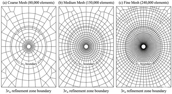
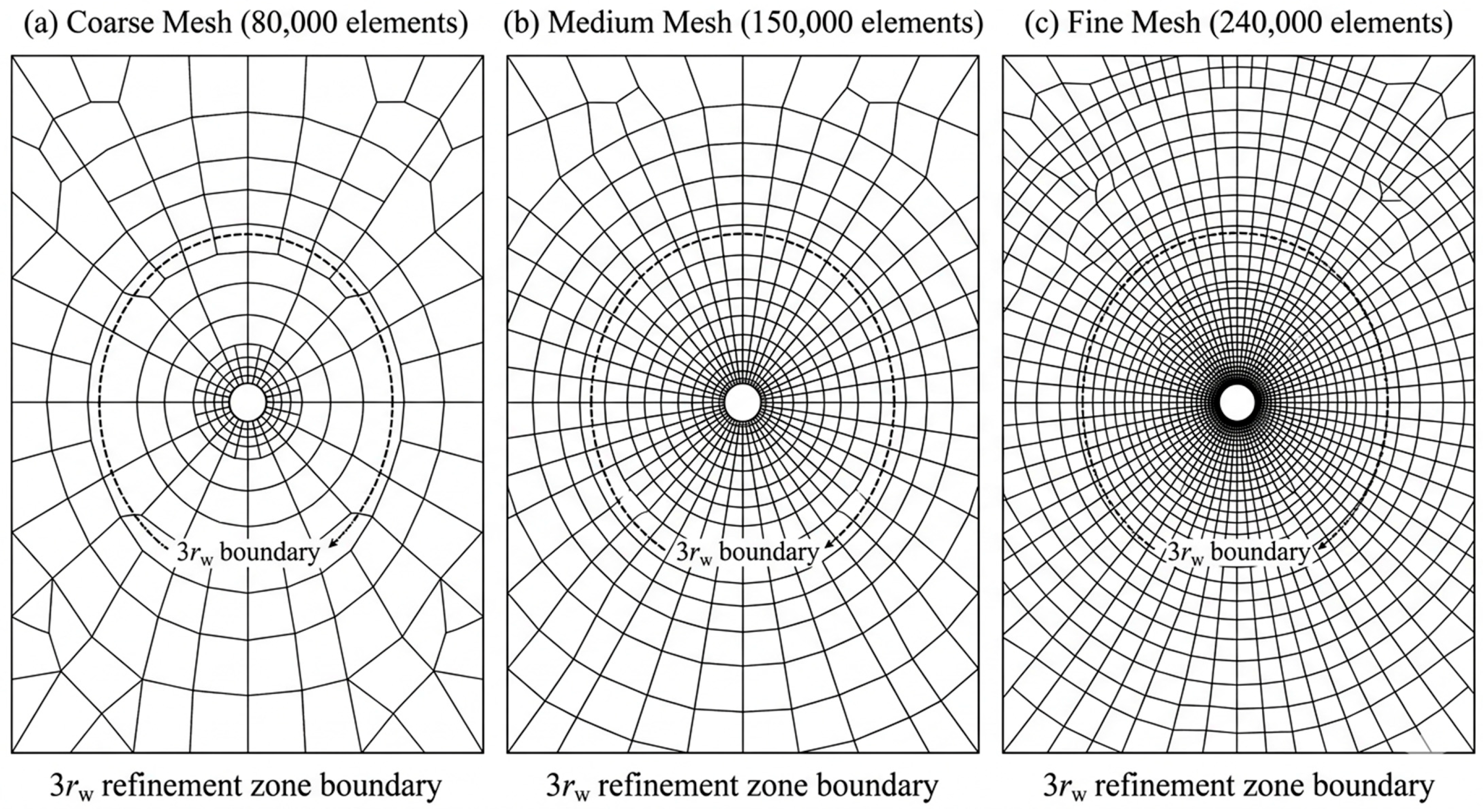
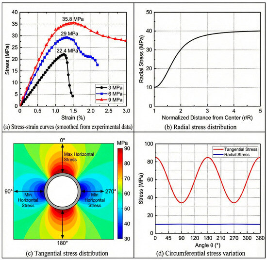
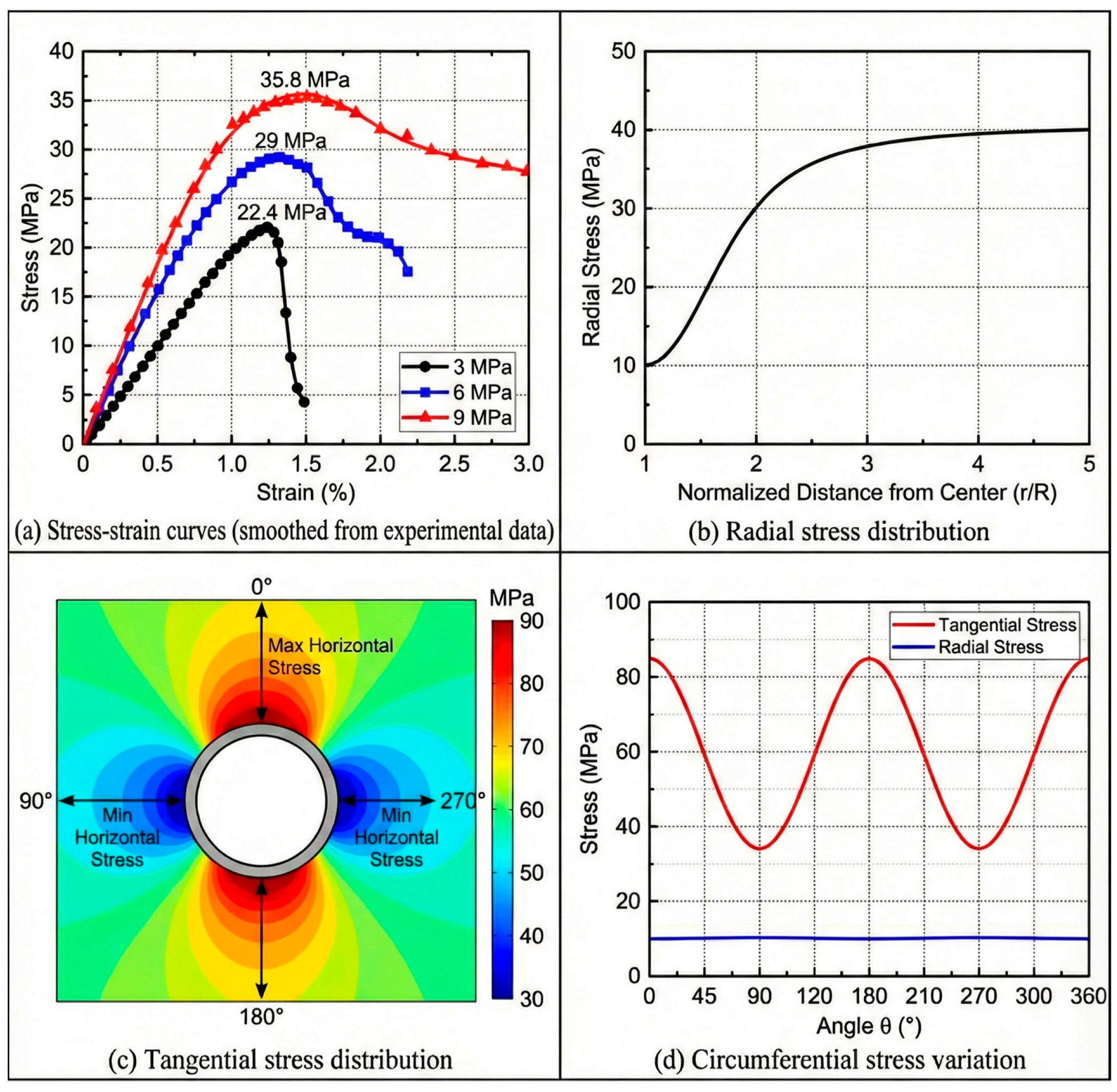
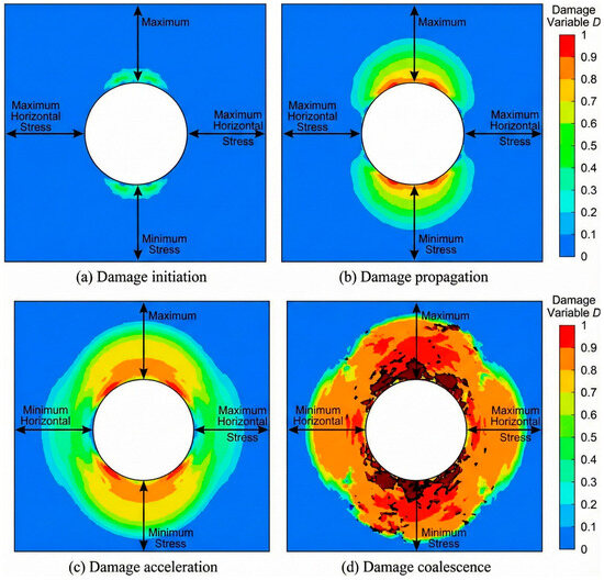
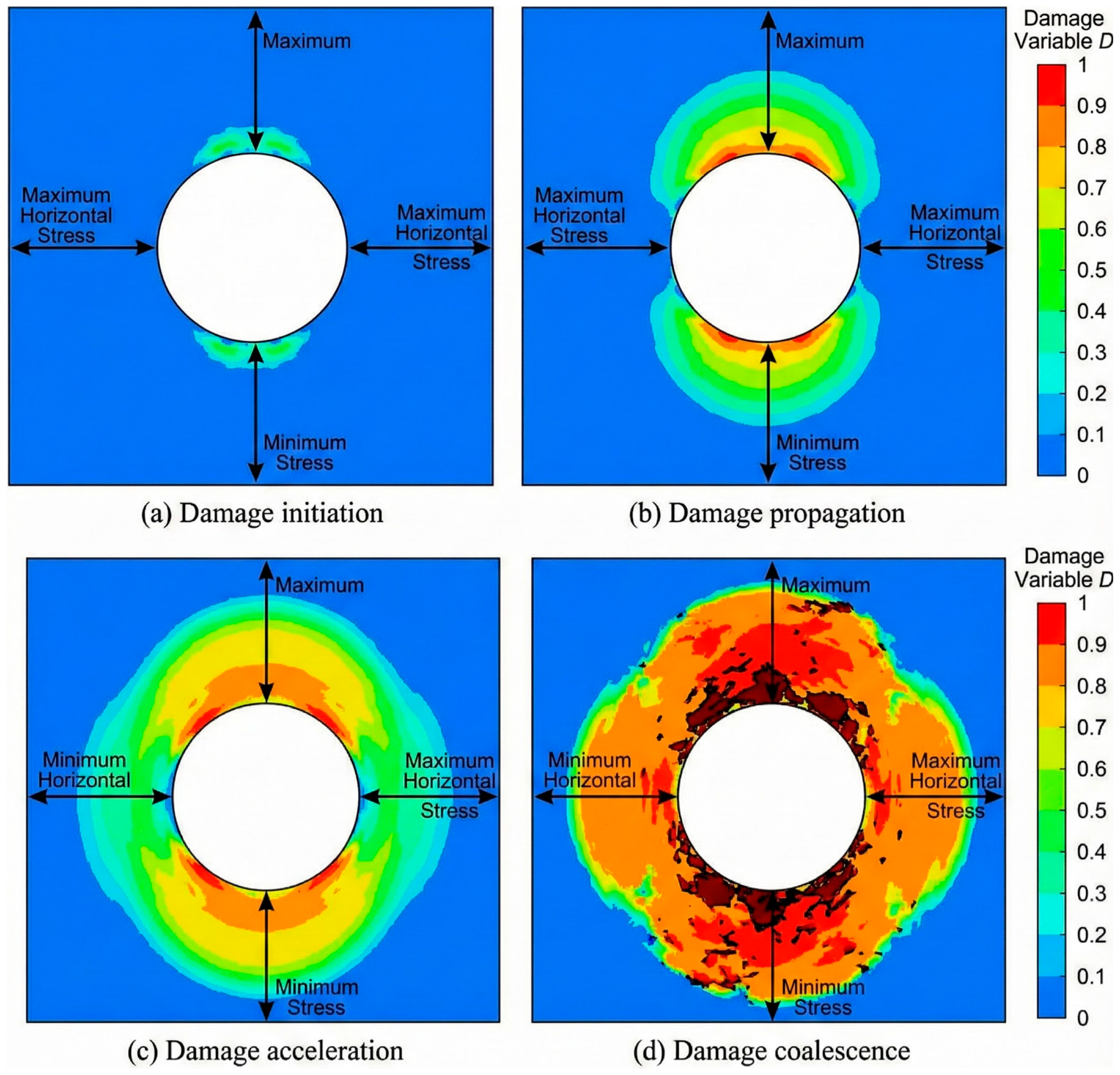
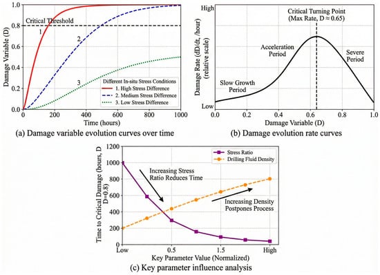
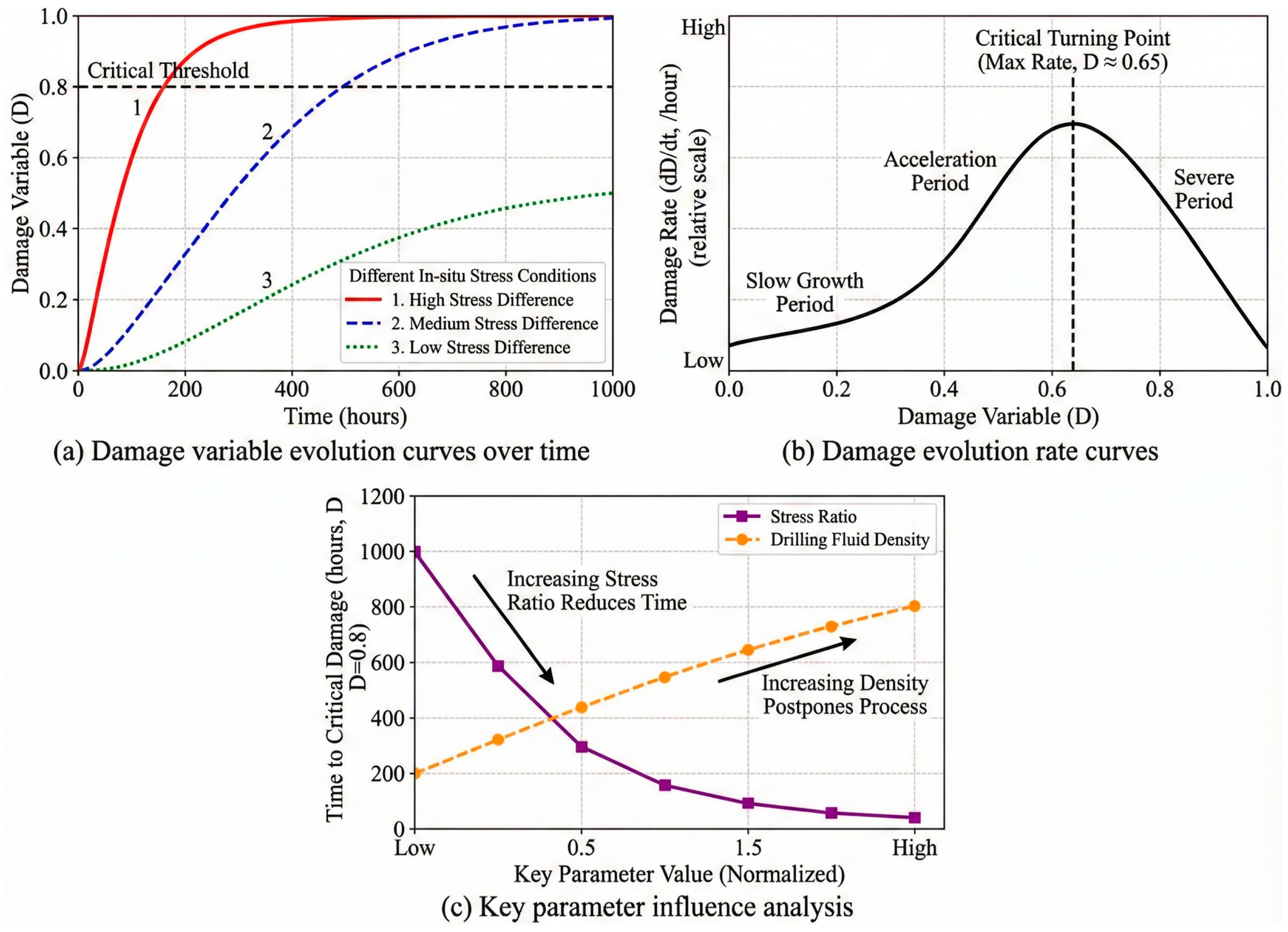
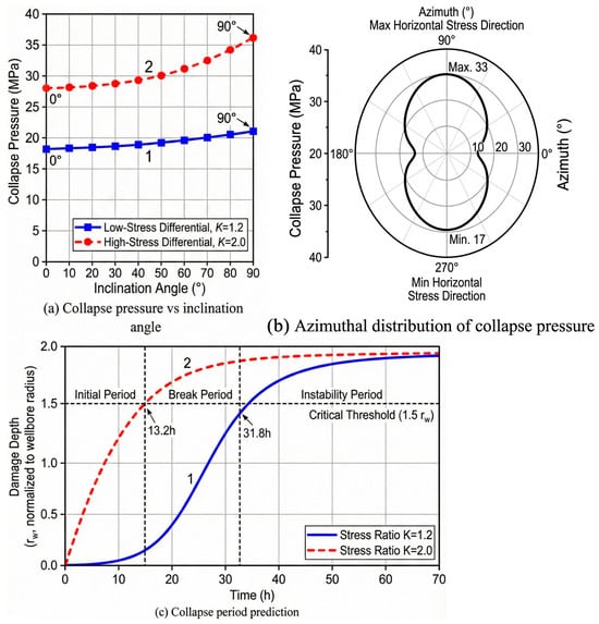
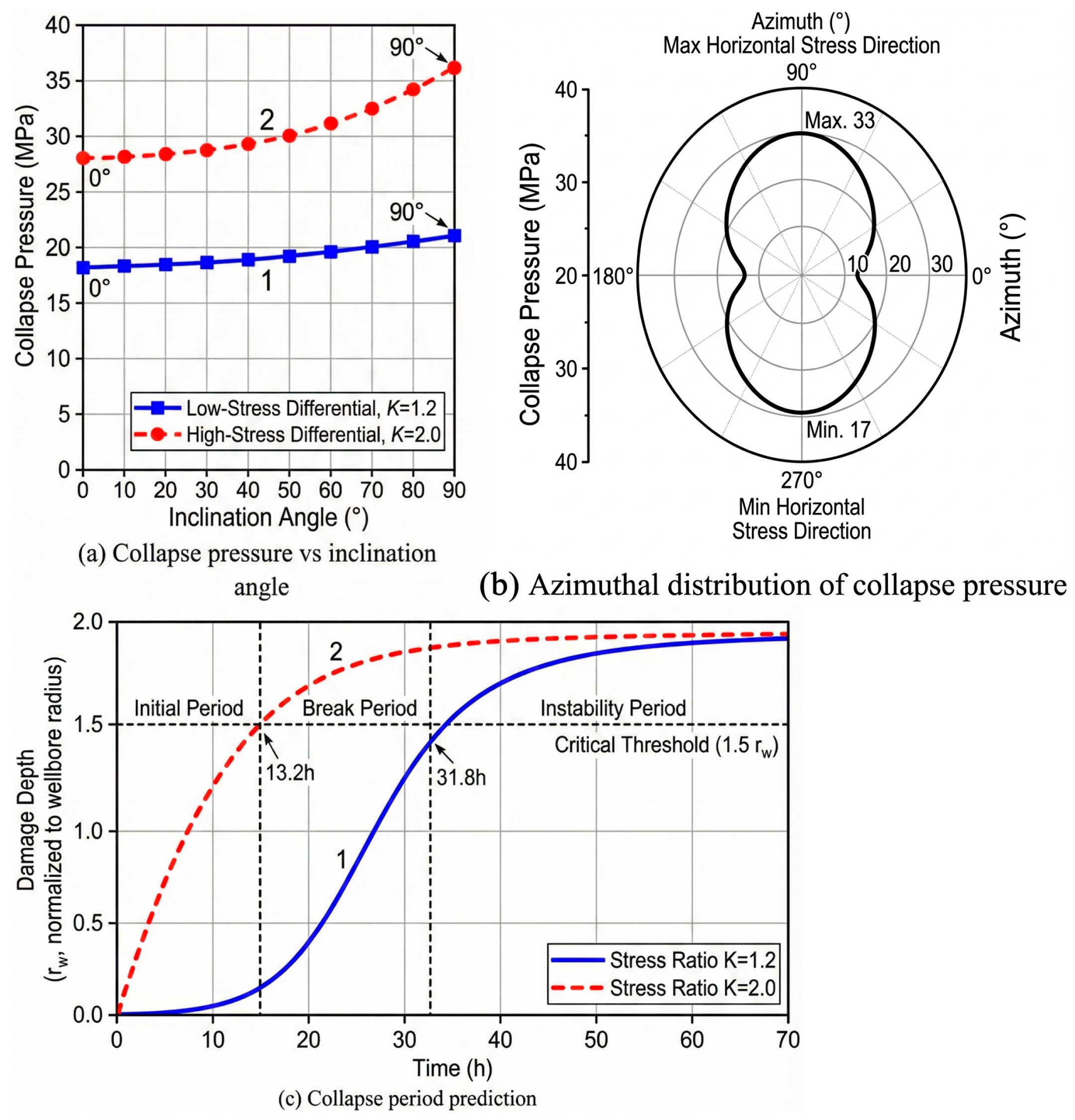

Disclaimer/Publisher’s Note: The statements, opinions and data contained in all publications are solely those of the individual author(s) and contributor(s) and not of MDPI and/or the editor(s). MDPI and/or the editor(s) disclaim responsibility for any injury to people or property resulting from any ideas, methods, instructions or products referred to in the content. |
© 2026 by the authors. Licensee MDPI, Basel, Switzerland. This article is an open access article distributed under the terms and conditions of the Creative Commons Attribution (CC BY) license.