


Abstract
The increasing penetration of renewable energy has led to the large-scale integration of power electronic devices into the power grid. In weakly connected grids, such devices are connected to the grid via voltage source converters (VSCs) using grid-forming (GFM) control strategies. Ideally, the point of common coupling (PCC) with the grid is treated as a purely inductive circuit. However, in weak grids, the resistance-to-inductance ratio (R/X) cannot be ignored, which leads to the power coupling problem between active power (P) and reactive power (Q). This phenomenon impedes the precise control of P and Q, potentially resulting in steady-state power deviations and even system instability. Traditional power-decoupling methods based on virtual inductance (VI) have inherent limitations and fail to achieve complete decoupling between P and Q. To address this issue, this paper first analyzes the influencing factors of power coupling through an established power coupling model. Comparisons between the output voltage and the degree of power coupling demonstrate that power decoupling can be achieved by compensating the output voltage. Consequently, an improved power-decoupling strategy based on apparent power feedforward (APPFF) is proposed. The proposed APPFF method realizes complete P-Q decoupling, with a steady-state reactive power error of less than 1% of the rated value. Compared with the PI-decoupling method, the reactive power overshoot is reduced by about 24%, and no additional active power overshoot is introduced. Compared with the conventional virtual inductance method that only reduces coupling by up to 35%, APPFF eliminates the power coupling fundamentally while retaining the reactive power–voltage droop characteristics and fast dynamic response. By directly compensating the reference voltage to the ideal value using apparent power as the feedforward variable, the proposed method is essentially different from the existing voltage/angle compensation schemes. The feasibility and effectiveness of the proposed decoupling method are verified under various working conditions, such as different R/X ratios, line resistances and power references, through both Simulink simulations and experimental results.
1. Introduction
The rapid development of renewable energy has led to continuous growth in the installed capacity and power generation penetration rate of wind power, photovoltaic (PV) power, and other renewable energy sources, driving power systems to exhibit the “dual-high” characteristics of high-penetration renewable energy and high-penetration power electronic devices. The leapfrog development of distributed renewable energy has resulted in the integration of a large number of power electronic converters into the distribution network terminals and weakly connected areas [1]. Due to the long distance from the main grid, weak grid structure, and low short-circuit ratio (SCR), these areas have become the key nodes for renewable energy accommodation and stable grid operation [2,3]. However, the superposition of the intermittency and volatility of renewable energy generation and the low-inertia characteristics of power electronic devices has led to a continuous decline in the inertia of the terminal grid system, weakened damping characteristics, and a significant reduction in the voltage and frequency disturbance rejection capability [4,5]. As a result, problems such as wideband oscillation and transient instability occur frequently, posing severe challenges to the stable operation mechanism of traditional power systems [6].
As the core interface for renewable energy grid integration, the control strategy of power electronic converters directly determines the interaction characteristics between renewable energy sources and the power grid. The current mainstream grid-following control strategy takes the grid voltage as the synchronization reference and achieves power tracking through a phase-locked loop (PLL). It has matured operating characteristics in strong grid environments, but has inherent technical limitations in terminal weakly connected grids. The multi-loop control coupling of grid-following converters tends to introduce a negative damping effect; the weaker the grid strength, the more significant the negative damping impact, which is prone to causing synchronization instability and oscillation problems [7]. Meanwhile, it relies on the grid to provide a stable voltage and frequency reference and cannot actively participate in grid voltage and frequency regulation. In the event of grid disturbances, it is liable to disconnect from the grid due to the loss of reference signals, making it difficult to meet the stable operation requirements of terminal weak grids [8].
Against this background, the voltage source converter (VSC) is gradually becoming the mainstream topology for the grid integration of power electronic equipment, and its primary control, namely, the grid-forming control strategy, has emerged as a key technical approach to adapt to the grid integration of renewable energy in terminal weakly connected grids. Grid-forming converters abandon the reliance on grid reference signals; by simulating the rotor mechanical and stator electrical characteristics of synchronous generators (SGs), they independently establish a stable voltage and frequency reference and participate in grid operation with voltage source characteristics, thereby providing core voltage support for terminal weak grids [9]. Through virtual inertia and damping control, they can actively respond to system frequency variations, participate in primary frequency regulation, and compensate for the inertia deficiency of terminal weak grids. Simultaneously, they can provide flexible reactive power support, suppress voltage fluctuations, and improve the voltage stability margin at the point of common coupling (PCC), fundamentally enhancing the damping characteristics and disturbance rejection capability of weak grids [10].
In the current grid-forming control technologies, droop control and virtual synchronous generator (VSG) control are the mainstream control schemes [11,12]. Compared with droop control, VSG control incorporates inherent inertia and damping links while retaining droop characteristics. In the steady state, both schemes exhibit voltage source characteristics; in the dynamic state, however, VSG control possesses the inertia and damping links of synchronous generators. Both control schemes adopt two independent control loops (i.e., active power–frequency and reactive power–voltage loops) to regulate active and reactive power separately. Under ideal conditions, the line between the PCC and the power grid is regarded as a pure inductive line, where the droop characteristic is applicable, and the two control loops can realize independent power control. Nevertheless, in practical scenarios, transmission lines inherently contain resistive components, making it impossible to model the lines as pure inductances. This gives rise to power coupling between active and reactive power. The power-coupling phenomenon leads to inaccuracy in power control: when the converter injects reactive power into the grid to provide active voltage support capability, the power coupling exerts an impact on the active power, directly affecting the stability of the DC-link voltage and reducing the effective operating capability of the system.
To address the power-coupling issue, various solutions have been proposed in academic circles. Based on theoretical analysis, ref. [13] identified the potential resonance phenomenon of the system. Leveraging this finding, a practical decoupling controller was designed by means of the transfer function approximation method to suppress the coupling effect, and two pairs of conjugate poles were eliminated through the decoupling path. Ref. [14] established a unified dynamic power-coupling model based on the primary amplification factor array and relative gain array in the frequency domain, and conducted a comprehensive analysis of both VSG control and droop control schemes by utilizing this model. Ref. [15] established a coupling relationship between power and the power angle and the impedance ratio with the Dynamic Relative Gain Array (DRGA) and proposed a virtual power control technique based on DRGA and virtual impedance calculation. Ref. [16] proposed a novel enhanced power-decoupling method by using rotor current compensation. But this method needs relatively accurate parameters of the doubly fed motor and line impedance. Ref. [17] proposed a dynamic virtual resistance (DVR) decoupling method that achieves power decoupling by dynamically modifying the virtual resistance, which can provide near-perfect power decoupling, according to simulations. The power control strategy is based on the virtual power angle on the basis of virtual inductance control, taking both the R/X ratio and power angle into consideration. The virtual power angle value calculated via theoretical formulas is employed to improve the power loop control, which enhances the power decoupling effect under a wide range of power angles, suppresses the fluctuation of reactive power, and evaluates the system stability by using the amplitude-phase motion equation criterion. Ref. [18] proposed a power-decoupling control strategy based on feedback linearization.
In addition to the methods mentioned in the aforementioned literature, another commonly used approach to achieve power decoupling is to introduce virtual inductance or virtual resistance, making the line impedance purely inductive and, thus, achieving power decoupling. Ref. [19] proposed a power-decoupling strategy based on voltage compensation, incorporating virtual negative impedance control and grid compensation control simultaneously in the reactive power–voltage control loop. This can significantly reduce the power-coupling phenomenon caused by the line impedance characteristics and the increase in the power angle. However, the proposed method cannot achieve complete decoupling. Ref. [20] proposed a q-axis voltage-drop-based power-decoupling control (QVPDC) method to further reduce the power coupling, which does not consider the d-axis voltage drop when applying the virtual inductor. Ref. [21] put forward an optimized power-decoupling control strategy that provides either positive or negative voltage compensation for decoupling, thus achieving efficient power decoupling under grid impedances with different R/X ratios. Ref. [22] uses “virtual negative resistance” to reduce the power coupling caused by resistive lines and minimize the voltage drop in parallel system outputs. Ref. [23] proposed a virtual inductance (VI)-based quasi-stationary approximation, which only considers fundamental components. But this method cannot achieve full power decoupling. It can be seen that the virtual impedance decoupling method has defects in both decoupling capability and response speed.
In this paper, the power-coupling phenomenon is analyzed in depth. Starting from the power calculation under the VSC grid-connected mode, the basic principle of VSG is introduced, and the mechanism underlying the limited decoupling capability of the virtual impedance method is revealed. A decoupling strategy based on apparent power feedforward is proposed, and the effectiveness of the proposed decoupling method is verified by both Simulink simulations and hardware-in-the-loop experimental results.
Compared with existing voltage compensation, virtual impedance, q-axis voltage drop, and feedback linearization methods, the proposed apparent power feedforward (APPFF) method has essential differences. Traditional methods either cannot achieve complete power decoupling, or lose the Q-U droop characteristic, or slow down the dynamic response. The APPFF scheme takes apparent power as the feedforward variable and directly compensates the voltage reference to the ideal value derived from the vector relationship. It achieves full P-Q decoupling without sacrificing inertia, damping, and droop characteristics, which is the main innovation of this paper.
2. VSG Control and Power Decoupling with Virtual Impedance
2.1. VSG Control Principle
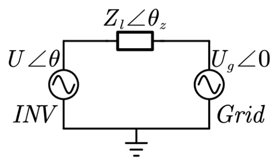
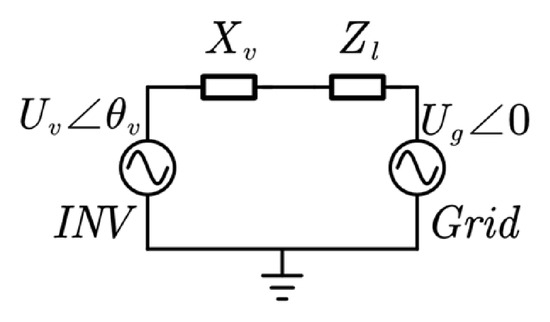
Under the condition of grid connection using voltage source mode, its state diagram is shown in Figure 1:
Figure 1.
Simplified diagram of voltage source converter connected to the grid.
Assuming the converter output voltage is U∠θ, which is connected to the grid through a line impedance Zl, when the line impedance is Zl∠θz, the apparent power of the converter can be expressed as
Thus,
In a steady state, the phase difference θ between the output voltage and the bus voltage is a small value, and it is approximately assumed that sin θ = θ and cos θ = 1. The above equation reduces to
Therefore, the output power of the converter is influenced by three factors: grid voltage, converter voltage, and connection impedance. The grid voltage can be approximately considered as fixed, while the converter voltage controls the power. Therefore, the impact of connection impedance on the output power of the converter is considered.
For weak terminal grids, the transmission line impedance of the converter’s point of common coupling to the grid can be regarded as an inductive circuit, where θz = 90°. The above formula can be simplified to
Differentiating active power P with respect to θ and reactive power Q with respect to U,
It can be known that when the line impedance is inductive, the active power of the converter is proportional to frequency, and the reactive power is proportional to voltage. At this time, the droop equation is satisfied as follows:
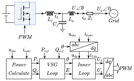
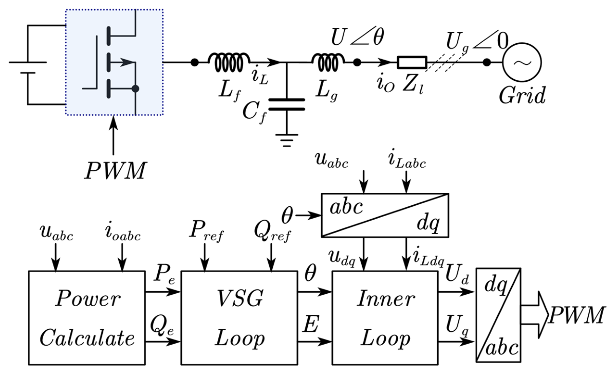
For typical grid-connected converters, the line from the point of common coupling to the grid is usually resistive–inductive, represented by the resistive–inductive ratio R/X. When current flows through the resistive component, it causes losses on the line. Therefore, the resistive component is generally reduced to minimize losses. However, in practice, the resistive component is usually small and can be neglected. Therefore, in droop control theory, the line impedance is typically regarded as a purely inductive line, which only affects the reactive power–voltage link without altering the characteristics of the power–frequency link; that is, the active power–frequency (P-f) and reactive power–voltage (Q-U) are two separately controlled links, both exhibiting droop characteristics. Based on this, the virtual synchronous generator control strategy simulates the rotor inertia and primary frequency regulation characteristics of a synchronous generator and includes excitation simulation functionality to mimic the electromagnetic mechanical characteristics of a synchronous generator, enabling power electronics equipment to simulate the external characteristics of traditional synchronous generators. The control structure diagram of the grid-connected converter with virtual synchronous generator control strategy is shown in Figure 2 [24,25].
Figure 2.
Basic block diagram of VSG control.
2.2. Virtual Impedance Power Decoupling
For the scenario where the terminal-connected grid system converter draws or delivers power to the grid through a long transmission line, there is a resistive component in the line, resulting in power coupling between active power–frequency and reactive power–voltage. To achieve precise control of active and reactive power, it is necessary to mitigate or eliminate the impact of power coupling. In terms of topology hardware, a larger inductance can be added on the grid side to alleviate the power-coupling phenomenon. However, this method incurs significant power loss and increases the overall size and design difficulty of the converter, making it unsuitable as a method to eliminate power coupling. The power-coupling output by the converter mainly arises from the coupling phenomenon caused by the power of the fundamental component. Therefore, by ignoring the high-frequency components of the current, a method based on virtual impedance is adopted to address the power-coupling phenomenon. The expression for the grid-connected control outer-loop voltage reference value output in the virtual inductance decoupling method is as follows:
where Udref and Uqref are the reference voltages on the d-q axis, Xv is the virtual inductance, Xv = ωLv, and iod and ioq are the output currents on the d-q axis.
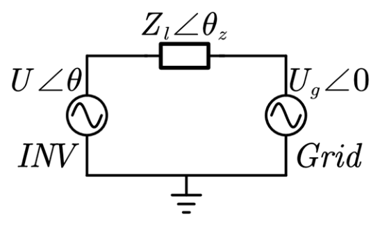
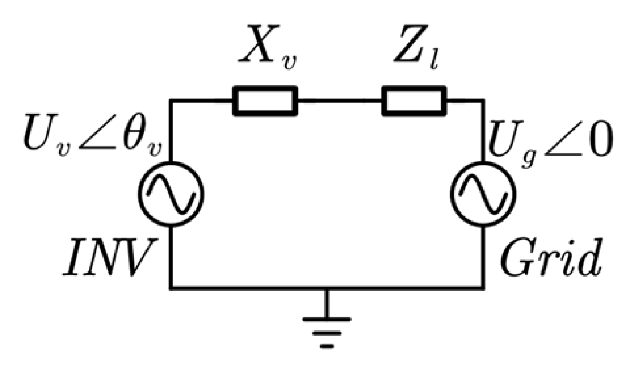
When the system introduces virtual impedance, the equivalent circuit is transformed as shown in Figure 3.
Figure 3.
Simplified grid-connected diagram of voltage source converter with virtual inductance.
Since virtual inductance does not consume active power, the expression for PQ at this time is as follows:
By taking partial derivatives of PQ with respect to θv and Uv at the steady-state linear operating point, we obtain the perturbation equation under the small-signal model:
where η11, η12, η21, and η22 are constants related to the steady-state operating point and the power grid, as shown below:
When using virtual inductance, in order to eliminate the coupling relationship between P and Q, it is necessary to make η12 equal to 0 to completely eliminate the coupling effect. According to Equation (10), it is clear that this is a complex coupling relationship, and it is difficult to directly draw conclusions from the expression. Typically, the line impedance ratio R/X cannot be ignored, but its value is relatively small, causing the active power P to be clamped by the grid voltage. Usually, it is only related to the active power reference value Pref and the grid frequency. Changes in reactive power Q result in small changes in active power P, while reactive power is highly influenced by the grid voltage and grid-connected current. Therefore, to simplify the equation, ΔUv is approximately equivalent to the reactive power component in the droop control equation; that is,
Thus, Equation (9) can be transformed into
When using virtual inductance decoupling, let ξ represent the degree of decoupling. ξ is expressed as
Combined with (12), it can be concluded that ξ satisfies
When PQ is completely decoupled, ξ = 0. At this point, it can be seen that the formula satisfies this condition, and the numerator must be 0; that is, η21 = 0.
Based on the aforementioned analysis, the PQ coupling phenomenon is analyzed according to the parameters presented in Table 1.
Table 1.
Parameters of the system.
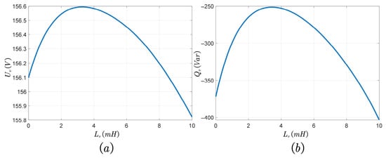
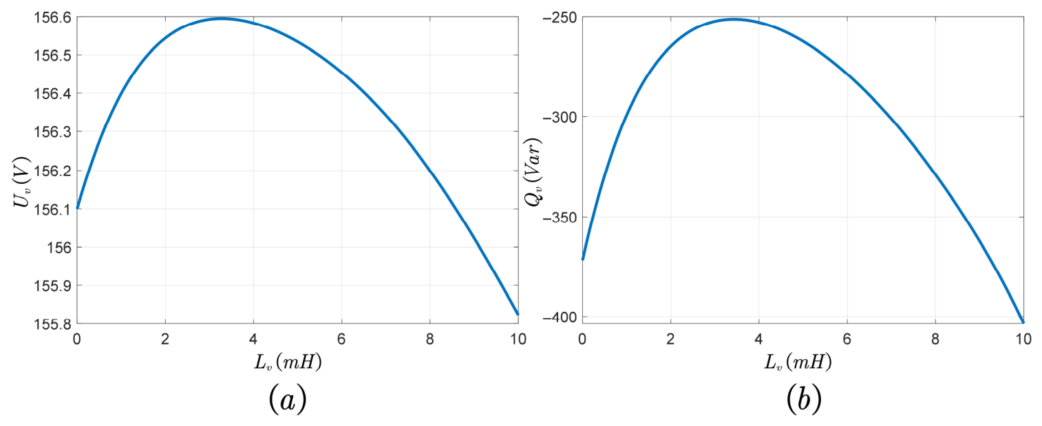
When the virtual inductance Lv changes, its decoupling capability can be reflected by Q, Uv, and the virtual angle θv. Thus, the decoupling capability of VI in this case is shown in Figure 4.
Figure 4.
Relationship curve of virtual inductance decoupling effect varying with Lv.
As can be seen from Figure 4a,b, the decoupling capability of the virtual inductance is not a monotonic function of the virtual inductance’s own size, and there is a clear peak. They exhibit the same variation trend. When the virtual inductance value Lv is less than 3.44 mH, the decoupling capability gradually increases. When Lv is greater than 3.44 mH, the decoupling capability of the virtual inductance gradually decreases, and the decoupling capability significantly weakens as Lv increases. When Lv is large, it actually enhances the coupling relationship compared with when there is no decoupling strategy. The decoupling capability is greatest at a virtual inductance value Lv = 3.44 mH, but overall, there is no specific Lv that fully decouples PQ. Therefore, the decoupling capability of the virtual inductance is limited. In fact, the decoupling performance of the virtual inductance comes from its positive compensation for the output voltage. However, when the line impedance ratio R/X is large, ioq is much smaller than iod, and the beneficial effect of Xvioq on the voltage cannot compensate for the negative effect of −Xviod on the voltage. In this case, increasing the virtual inductance value will exacerbate the PQ power-coupling phenomenon [26].
3. Apparent Power Feedforward Power Decoupling
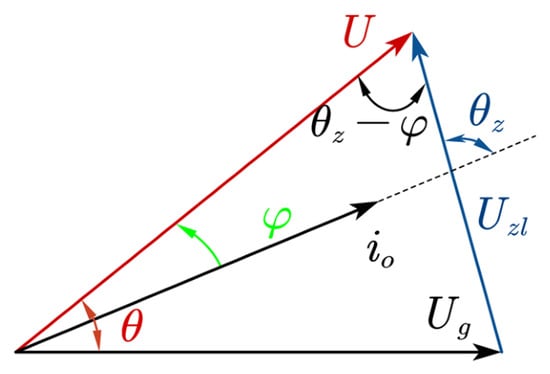
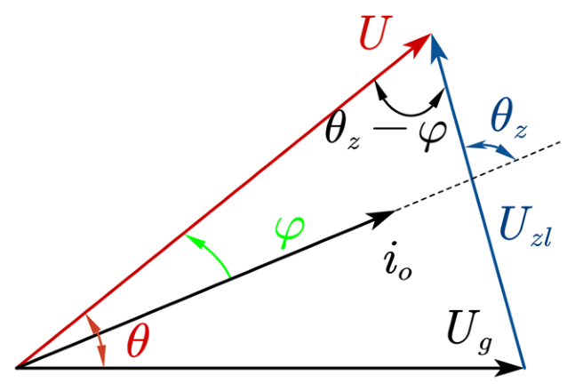
In fact, to completely eliminate the power-coupling phenomenon, feedforward compensation can be applied to the output voltage reference value E of the power outer loop for the system, so that the voltage reference reaches the theoretical voltage Uideal, thereby eliminating the power coupling between P and Q [27]. Since the voltage offset in the converter system is caused by the voltage drop generated by inductive current, the overall apparent power S of the system can be introduced to achieve power decoupling. The apparent power feedforward (APPFF) method achieves power decoupling by correlating the output voltage and current of the converter itself with the impedance value of the connecting inductance and compensating for the difference between the output voltage U and the ideal voltage Uideal in the Q-U loop of the power outer loop. The vector diagram of the system using the VSG control strategy is shown in Figure 5.
Figure 5.
Voltage and current vector diagram under steady-state VSG control.
According to the sine theorem, ideally, Uideal should satisfy
where θ and φ represent the power angle and power factor angle, and θz represents the impedance angle of the transmission line. The feedforward compensation method actually compensates for the output voltage value, thus requiring the voltage reference value E to be increased to Uideal. The specific magnitude of the ideal voltage Uideal at this time can be obtained using Equation (15). When power decoupling, φ = 0. Then, θ can be calculated. Furthermore, Uideal can be determined.
By compensating the voltage reference value to the ideal voltage reference value Uideal, power coupling can be completely eliminated. The expression is as follows:
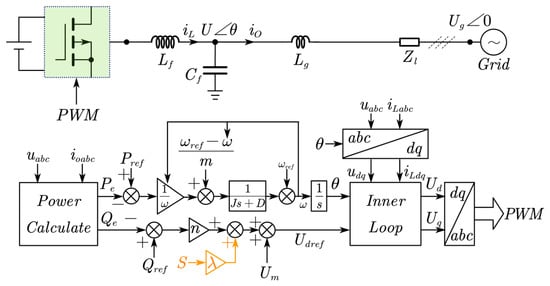
The feedforward coefficient λ is as follows, where S represents the apparent power of the system, and Um represents the grid voltage amplitude:
The feedforward coefficient λ is calculated online using the grid voltage amplitude, line inductance, and apparent power. For variable grid impedance conditions, the R/X ratio can be identified online, and the coefficient λ can be adjusted adaptively to maintain good decoupling performance. This design improves the engineering practicability of the APPFF method and reduces the sensitivity to parameter mismatch.
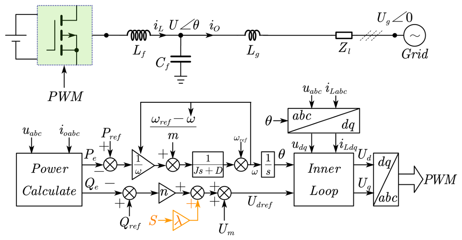
The APPFF control block diagram is shown in Figure 6.
Figure 6.
Control block diagram of APPFF decoupling method.
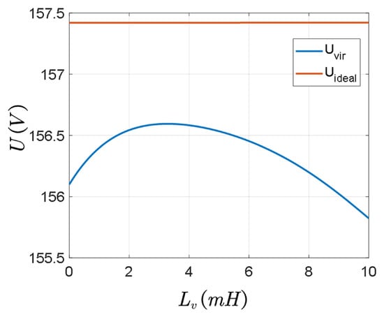
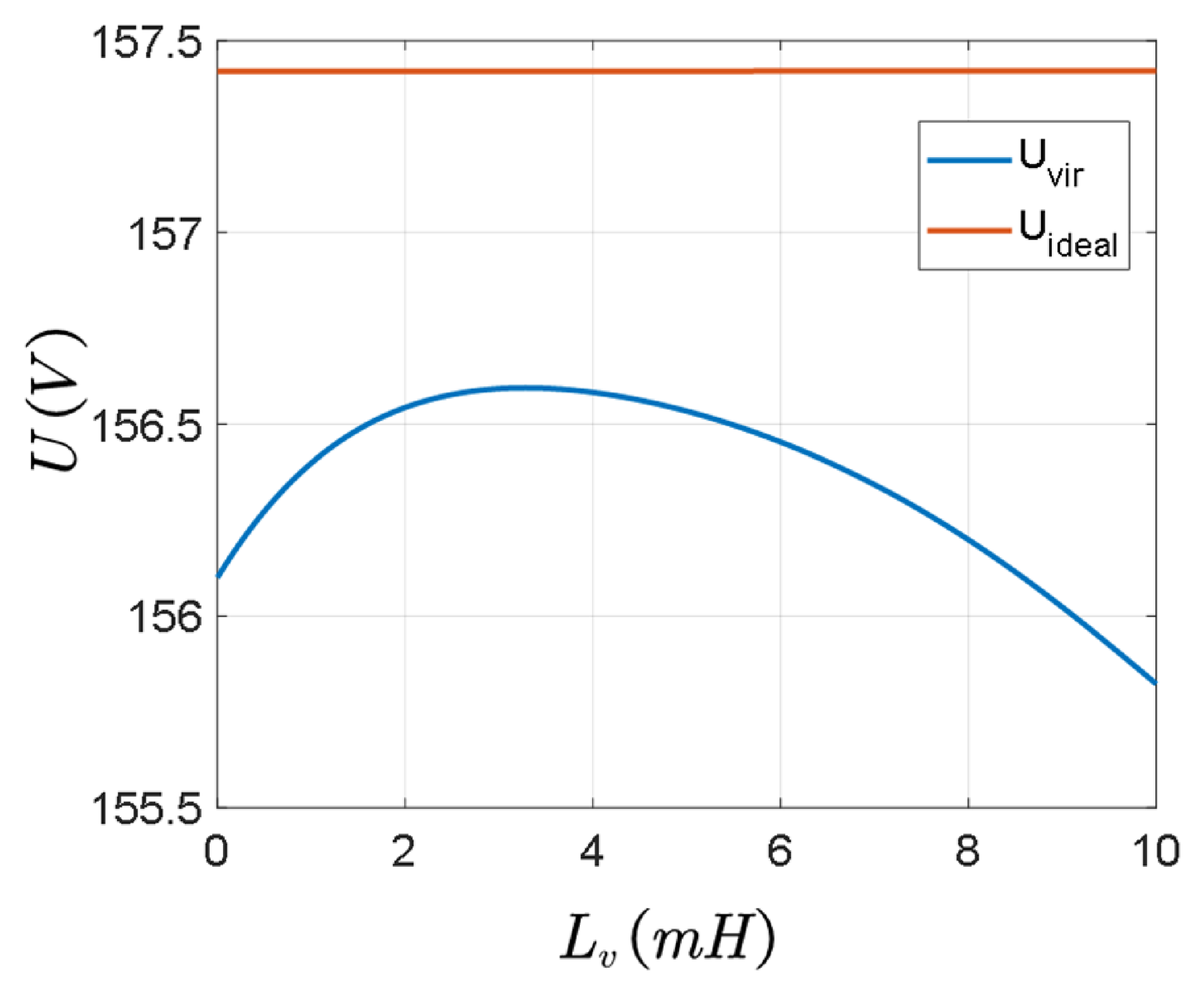
As shown in Figure 7, under the aforementioned analysis conditions, the voltage for achieving complete decoupling of PQ in an ideal situation should be 157.42 V. However, the grid voltage is 155.5 V. Therefore, the feedforward compensation coefficient λ can be calculated as λ = 0.00064. The APPFF compensation method can ensure that the output voltage reference value reaches the ideal decoupling voltage, thereby effectively eliminating power coupling.
Figure 7.
Ideal reference output voltage and output voltage with VI-decoupling method.
4. Simulation and Experimental Verification
4.1. Simulation Analysis
To verify the proposed VI-decoupling method and the APPFF decoupling method, relevant simulations were set up in Simulink 2022a. The parameters are shown in Table 1.
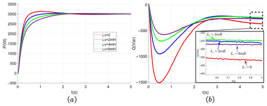
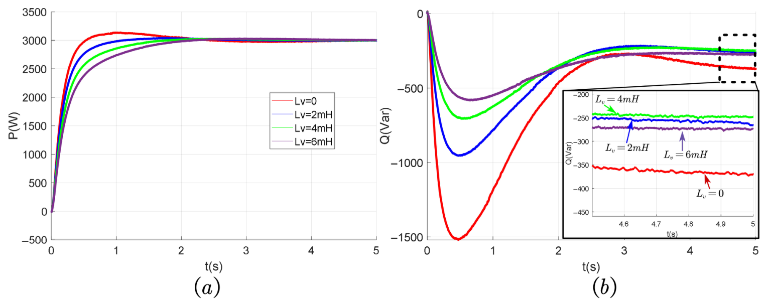
Figure 8 plots the active and reactive power curves under the virtual inductance-based power-decoupling strategy, with varying virtual inductance values. The simulation results indicate that, without decoupling control, the system settles at P = 3 kW and Q = −380 Var in a steady state. At this operating point, the active and reactive power exhibit significant coupling, degrading the overall control accuracy. When Lv = 2 mH, the steady-state reactive power reduces to Q = −270 Var, demonstrating an alleviation of the power-coupling phenomenon. Similarly, increasing Lv to 4 mH further suppresses the coupling, with Q stabilizing at −250 Var. However, a further increase to Lv = 6 mH results in a higher Q of −280 Var, indicating a deterioration in the decoupling performance.
Figure 8.
Decoupling effect under varying virtual inductance values in simulation. (a) Output active power. (b) Output reactive power.
Collectively, these results confirm that, while the virtual inductance strategy offers a discernible improvement in decoupling performance compared with the non-decoupling case, complete PQ decoupling is unattainable. The method exhibits a distinct peak in its decoupling capability: performance enhances with an increase in Lv up to this optimal point, after which further increments in Lv lead to degraded decoupling effects. Furthermore, the results illustrate that when the line impedance ratio R/X is large, the virtual inductance decoupling method fails to fully eliminate the power coupling.
Figure 9 illustrates the decoupling effects under different converter outputs using various decoupling methods. The simulation curves reveal that there is severe power coupling between P and Q without decoupling control. The VI-decoupling method shows some decoupling effect, but it cannot completely eliminate the coupling. The PI method can completely eliminate the coupling phenomenon. This is because PI tracks the input signal without steady-state error. When there is a steady-state error in the input signal, i.e., Qref − Q, the integral component in the PI controller gradually increases or decreases, causing the voltage reference value E to gradually increase or decrease, ultimately leading to Qref − Q = 0. However, using PI control cannot restore the droop characteristic of Q-U. That is, in a general droop control system, when the grid voltage changes, the reactive power output by the converter will also follow the grid voltage change based on the droop characteristic. Although using PI control can stably maintain the reactive power Q = Qref when the converter outputs, it also causes it to lose the droop characteristic and, thus, cannot support the grid. Additionally, the introduction of the integral component reduces the stability of the entire system. According to the simulation diagram, the PI control decoupling under the step change of active power leads to overshoot of active power, with a maximum active power of 3200 W. In contrast, the virtual inductance decoupling method will reduce the overshoot of the system, while the APPFF method is consistent with the active power curve without decoupling, with a maximum active power of 3110 W. Obviously, while achieving decoupling capability, the APPFF method will not cause overshoot of active power. Meanwhile, when the active power step reaches 3000 W, the inertia and damping of VSG itself will cause fluctuations in reactive power. The APPFF method achieves complete power decoupling at t = 5 s steady state, with a final reactive power of 0 and a maximum reactive power value of −1150 Var, while the PI-decoupling method has a maximum reactive power value of −1510 Var. It can be seen that the APPFF method significantly reduces reactive power overshoot while achieving complete decoupling. And compared with the VI method, it can achieve complete power decoupling.
Figure 9.
Comparison of the effects of different decoupling methods in simulation. (a) Output active power. (b) Output reactive power.
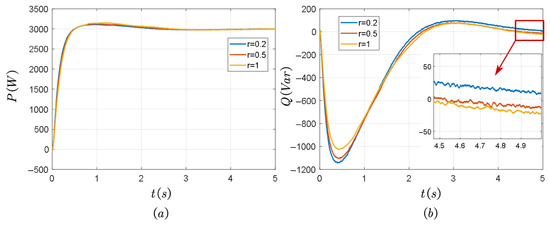
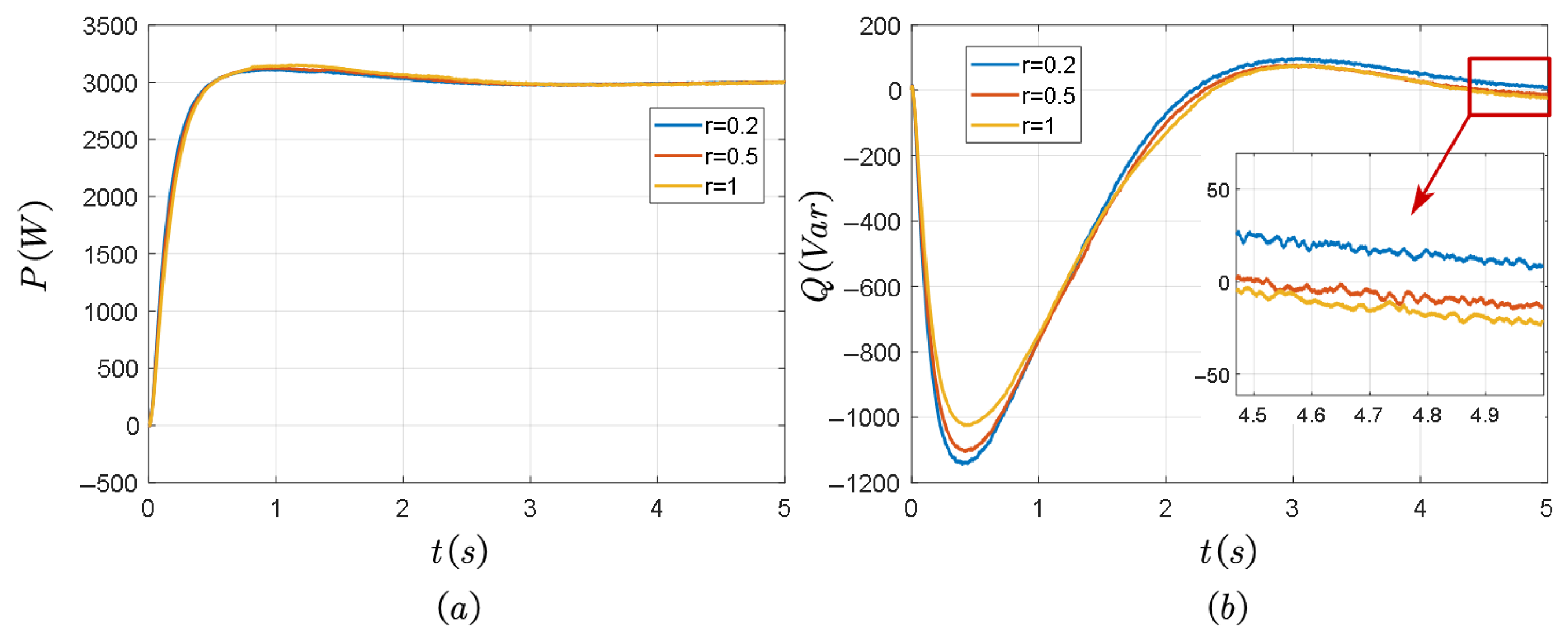
As shown in Figure 10, the active and reactive power curves of power decoupling using the APPFF method under different transmission line resistances are presented. It can be seen that when the inductance of the transmission line remains constant and the impedance ratio R/X of the line changes with the change in the connecting transmission line resistances, there is no significant change in the active power curve and reactive power curve under the APPFF method, and complete power decoupling can be achieved in all three states of Rline = 0.2 Ω/0.5 Ω/1 Ω.
Figure 10.
Decoupling effect with APPFF under different transmission line resistances. (a) Output active power. (b) Output reactive power.
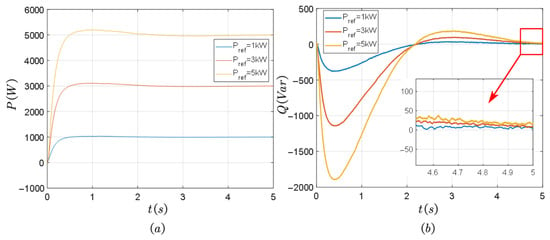
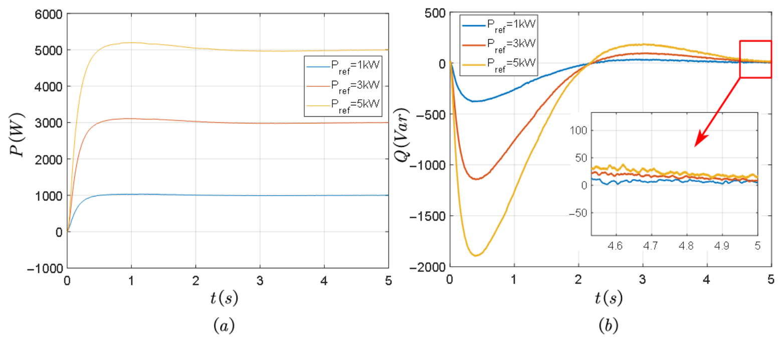
Figure 11 shows the active power and reactive power curves decoupled using the APPFF method under different active power reference values. When Pref changes, complete power decoupling can be achieved using the APPFF method at t = 5 s. For the maximum reactive power of the three, it can be noted that when Pref = 1 kW, Qmax = −379 Var, and Pref = 3 kW, Qmax = −1140 Var. When Pref = 5 kw, Qmax = −1891 Var. Obviously, they are proportional to each other, so the APPFF method itself will not cause additional overshoot and can achieve complete power-decoupling capability.
Figure 11.
Decoupling effect with APPFF under different active power reference values. (a) Output active power. (b) Output reactive power.
4.2. Experimental Verification
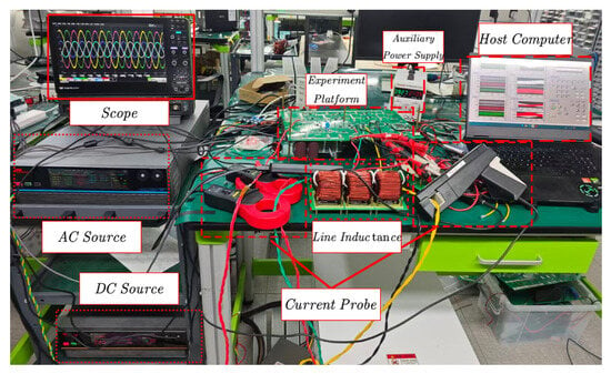
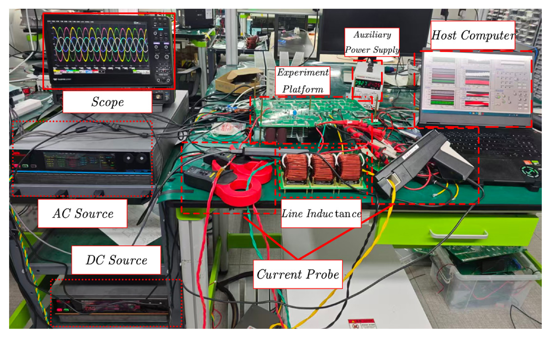
To further validate the effectiveness of the proposed control strategies, comprehensive experiments were conducted on a dedicated experimental platform (Figure 12). The system utilized a TI DSP TMS320F28379D (Texas Instruments, Dallas, TX, USA) as the core control chip, an Astrid Power PRD2006(ACTION Power Electric Co., Ltd., Xi’an, China) bidirectional programmable DC power supply as the DC source, and a PRE2020S (ACTION Power Electric Co., Ltd., Xi’an, China) as the grid emulator. Detailed grid parameters and specifications of the experimental setup are summarized in Table 1.
Figure 12.
Experimental platform.
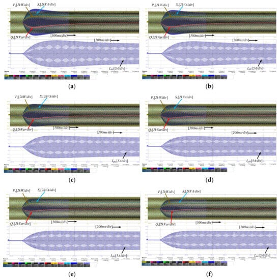
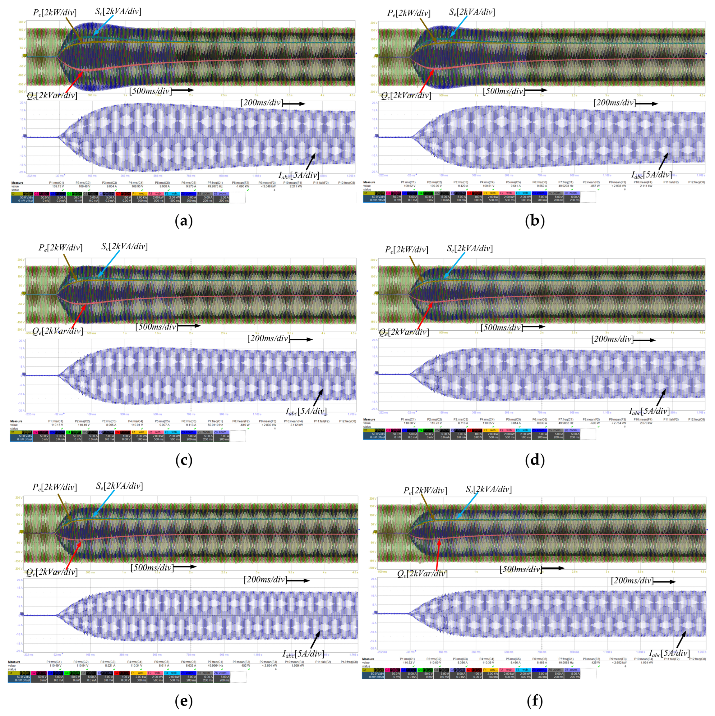
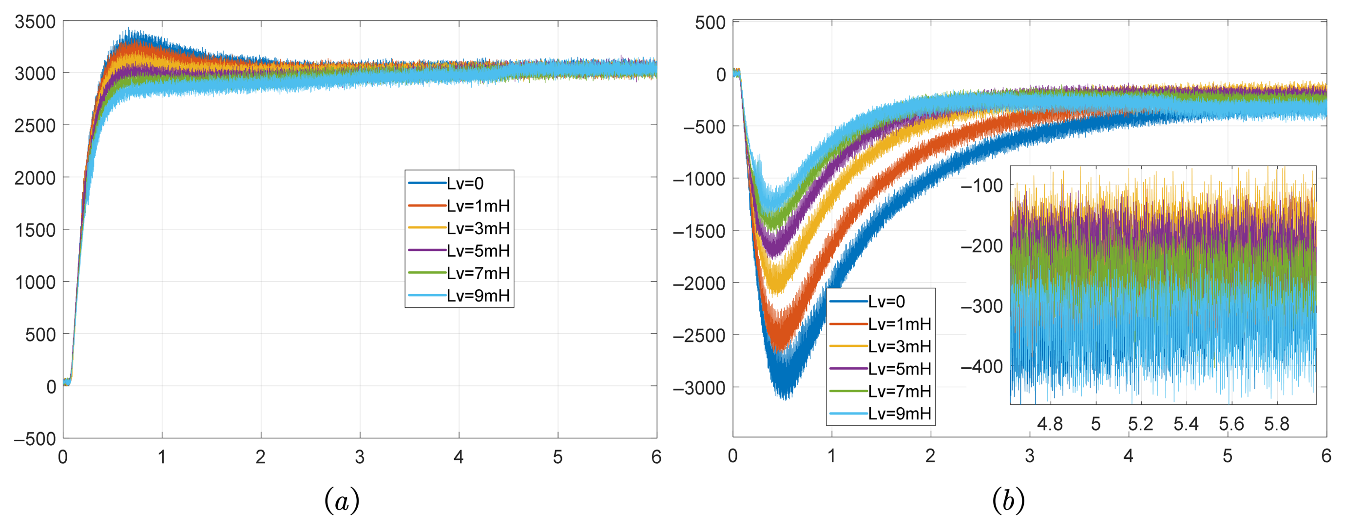
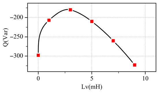
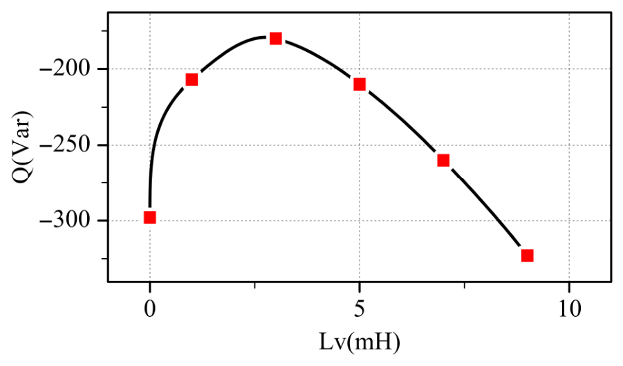
Figure 13a–f shows the waveforms under different virtual inductance experimental conditions. The active power and reactive power waveforms in the figure are extracted separately and redrawn into two independent images, which are Figure 14a,b. As illustrated in Figure 15, the absolute value of the steady-state reactive power (at P = 3 kW) initially decreases and then increases as Lv rises. As illustrated in Figure 15, the optimal decoupling performance is achieved at Lv = 3 mH, where the reactive power Q is closest to zero. However, complete PQ decoupling is unattainable with this method. At Lv = 9 mH, Q stabilizes at −323 Var, which exhibits no decoupling effect relative to the case of Lv = 0 and instead exacerbates the power-coupling phenomenon. These experimental findings are in excellent agreement with the simulation and theoretical results, thereby confirming the inherent limitations of the virtual inductance (VI) approach.
Figure 13.
Waveforms of three-phase voltage and current under different virtual inductance va-ues. (a) Lv = 0. (b) Lv = 1 mH. (c) Lv = 3 mH. (d) Lv = 5 mH. (e) Lv = 7 mH. (f) Lv = 9 mH.
Figure 14.
Waveforms of active power and reactive power under different virtual inductance values. (a) Output active power. (b) Output reactive power.
Figure 15.
Steady-state values of reactive power under different virtual inductance values.
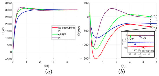
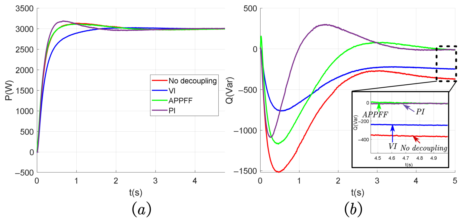
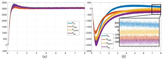
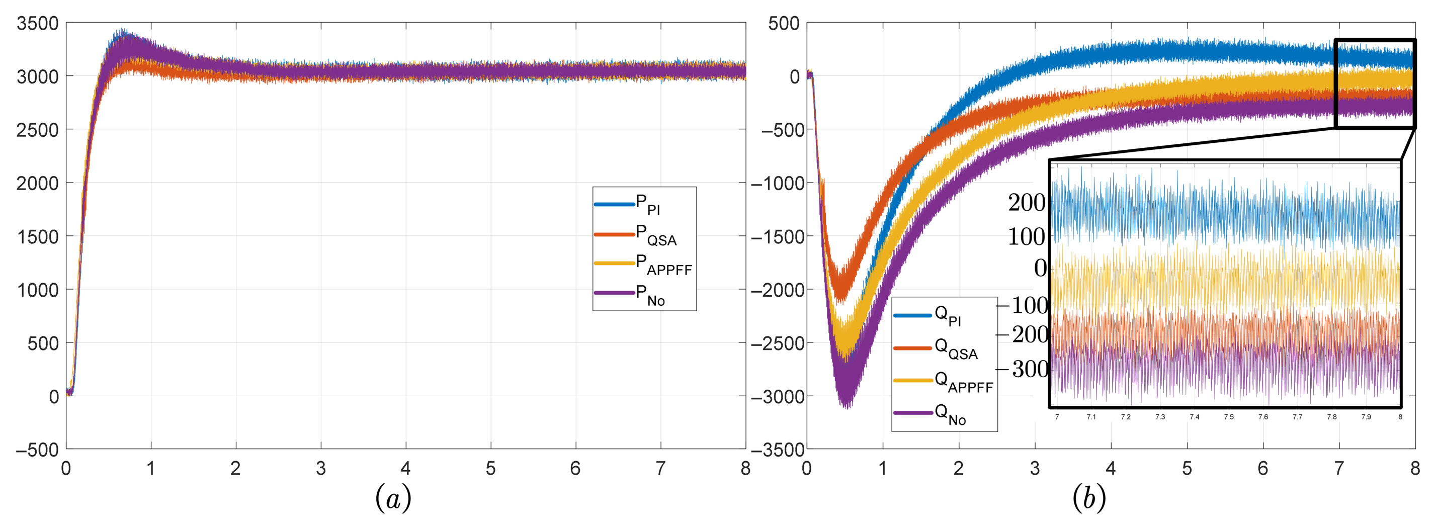
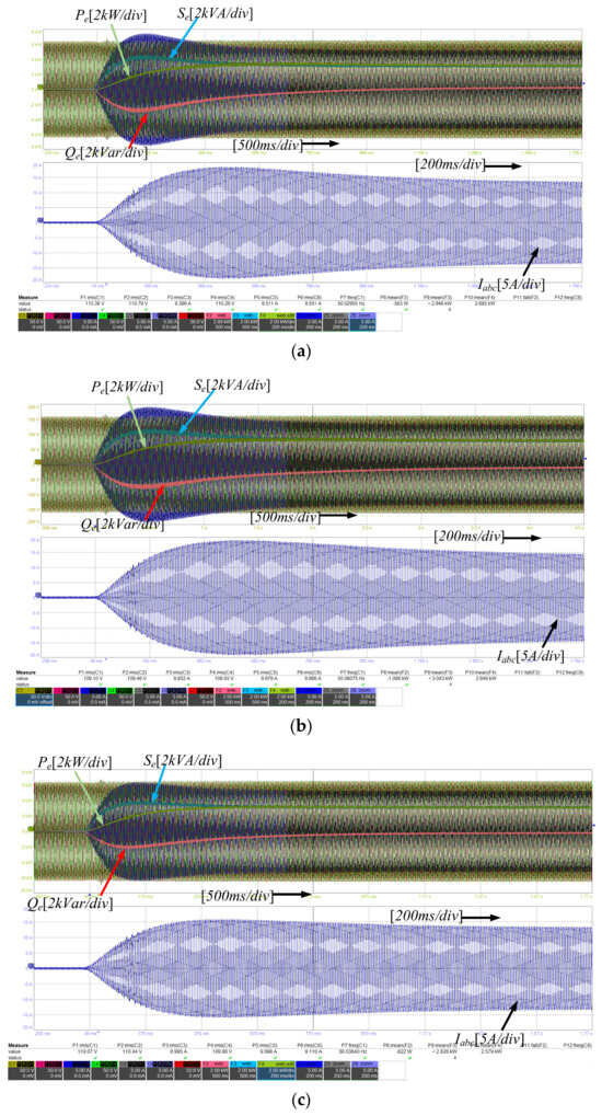
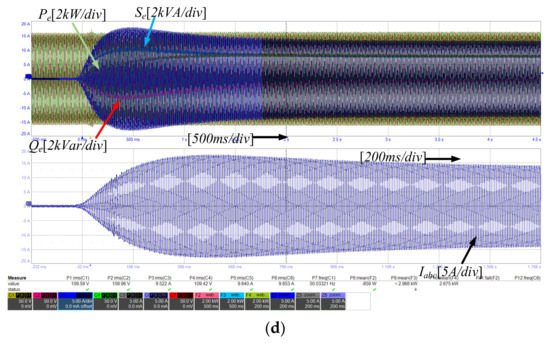
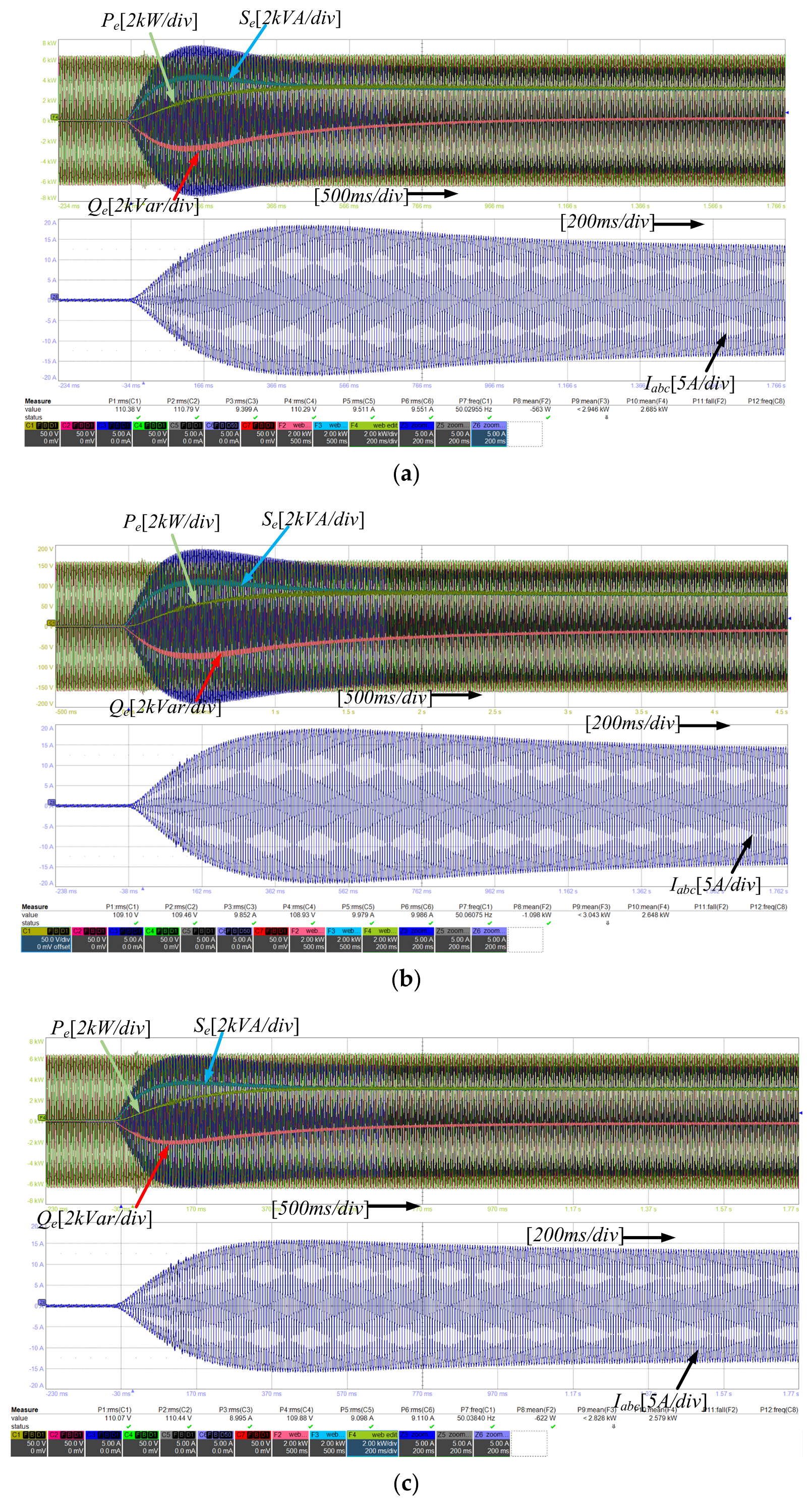
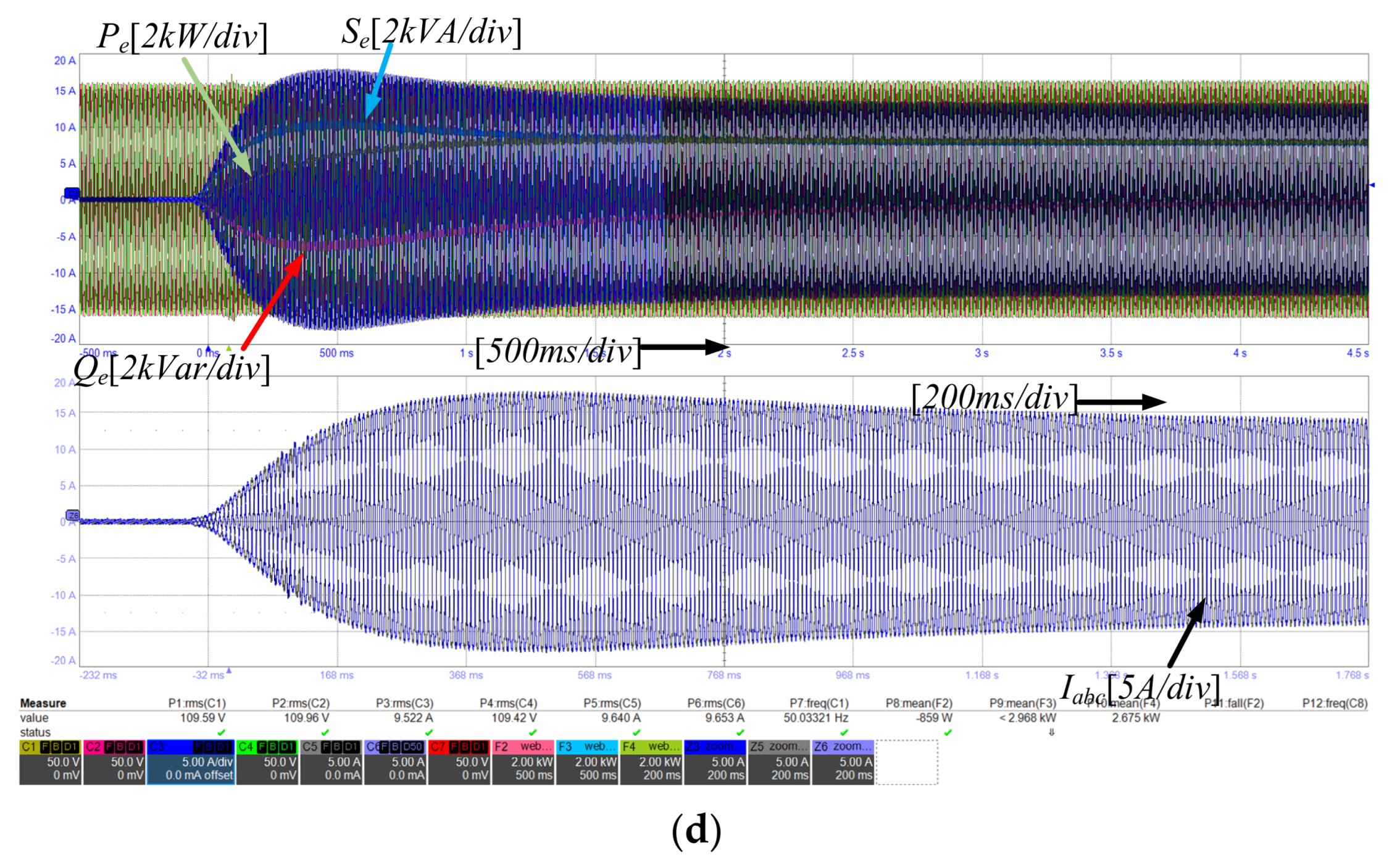
Figure 16 compares the active and reactive power dynamics achieved by various decoupling methods. Figure 17 presents the corresponding experimental results for reactive power decoupling, PI control, virtual inductance (VI), and adaptive pre-decoupling feedforward (APPFF) strategies. Analysis of the curves in Figure 16 reveals that both the APPFF and PI methods effectively eliminate power coupling. However, the PI method suffers from a critical limitation: it fails to regulate reactive power during grid voltage variations. The VI method demonstrates a moderate decoupling capability but cannot achieve full PQ decoupling. Compared with Figure 16a, all three decoupling methods exert minimal influence on the active power response.
Figure 16.
Experimental results of active power and reactive power with different decoupling methods. (a) Output active power. (b) Output reactive power.
Figure 17.
Experimental waveforms of voltage and current for different decoupling methods. (a) No decoupling. (b) PI decoupling. (c) VI decoupling. (d) APPFF decoupling.
In summary, the PI method is the simplest and most straightforward to implement, requiring no complex computations and accommodating any active power setpoint. Its principal drawbacks are the induced current overshoot and the loss of the reactive power–voltage droop characteristic. The VI method offers partial decoupling and reduces the overall overshoot amplitude during reference changes, yet it cannot achieve complete power decoupling. In contrast, the APPFF method minimizes overshoot and provides complete PQ decoupling, but it demands accurate knowledge of system parameters and requires adaptive compensation of varying magnitudes for different apparent power levels, leading to higher computational complexity. Collectively, these results highlight that the selection of an optimal decoupling strategy requires careful consideration of performance, complexity, and practical implementation constraints. A comprehensive summary of the advantages and limitations of each method is provided in Table 2.
Table 2.
Comparison of different power-decoupling methods.
5. Conclusions
This paper proposes a power-decoupling method based on apparent power feedforward compensation for the voltage source grid-connected converter in the VSG control scheme of weak terminal grids, addressing the power-coupling issue. Firstly, the power-coupling model of the voltage source grid-connected converter is analyzed, and based on this, the limitations of the virtual inductance decoupling method are examined. Then, an apparent power feedforward term is introduced to correct the reference voltage of droop control. According to the ideal state voltage value compensation, it eliminates the voltage difference caused by the line inductance–resistance ratio R/X in the corresponding state to achieve power-coupling elimination. Compared with the virtual inductance method, APPFF can eliminate power coupling, overcoming the limited decoupling capability of the VI-decoupling method. Compared with PI decoupling, APPFF does not exhibit voltage and current overshoot, possesses good dynamic response speed and steady-state decoupling capability, and retains the reactive power–voltage (Q-U) droop characteristic. The simulation and experimental results verify the correctness of the proposed method.
Author Contributions
Conceptualization, Z.Z.; methodology, B.L.; software, X.X.; data curation, X.X.; writing—original draft, X.X.; writing—review and editing, Z.Z. and B.L.; validation, X.Z.; supervision, F.J.; investigation, H.C., M.C. and W.W.; formal analysis, Z.Z. and F.J. All authors have read and agreed to the published version of the manuscript.
Funding
This research was supported by the State Grid Inner Mongolia Eastern Power Company Technology Project (Project No. 52660424000F).
Data Availability Statement
The original contributions presented in this study are included in this article; further inquiries can be directed to the corresponding author.
Conflicts of Interest
Authors Zhenyu Zhao, Bingqi Liu, and Xiaomin Zhao were employed by the State Grid Inner Mongolia Eastern Power Co., Ltd. The remaining authors declare that this research was conducted in the absence of any commercial or financial relationships that could be construed as a potential conflict of interest.
References
- Carrasco, J.M.; Franquelo, L.G.; Bialasiewicz, J.T.; Galvan, E.; PortilloGuisado, R.C.; Prats, M.A.M.; Leon, J.I.; Moreno-Alfonso, N. Power-Electronic Systems for the Grid Integration of Renewable Energy Sources: A Survey. IEEE Trans. Ind. Electron. 2006, 53, 1002–1016. [Google Scholar] [CrossRef] [Scilit]
- Li, Y.; Chi, Y.; Tian, X.; Liu, C.; Hu, J.; Fan, Y.; Fan, X.; Xiao, Y.; Wang, C. Research on Capacity Planning of Renewable Energy Grid Integration Based on Effective Short Circuit Ratio. In Proceedings of the 2020 IEEE Sustainable Power and Energy Conference (iSPEC), Chengdu, China, 23–25 November 2020. [Google Scholar]
- Zhou, J.; Ding, H.; Fan, S.; Zhang, Y.; Gole, A.M. Impact of Short-Circuit Ratio and Phase-Locked-Loop Parameters on the Small-Signal Behavior of a VSC-HVDC Converter. IEEE Trans. Power Deliv. 2014, 29, 2287–2296. [Google Scholar] [CrossRef] [Scilit]
- Shazon, M.N.H.; Deeba, S.R.; Modak, S.R. A Frequency and Voltage Stability-Based Load Shedding Technique for Low Inertia Power Systems. IEEE Access 2021, 9, 78947–78961. [Google Scholar] [CrossRef] [Scilit]
- Zhang, W.; Wen, Y.; Chung, C.Y. Inertia Security Evaluation and Application in Low-Inertia Power Systems. IEEE Trans. Power Syst. 2025, 40, 1725–1737. [Google Scholar] [CrossRef] [Scilit]
- Zhan, C.; Wu, H.; Wang, X.; Tian, J.; Wang, X.; Lu, Y. An Overview of Stability Studies of Grid-forming Voltage Source Converter. Proc. CSEE 2023, 6, 2339–2359. [Google Scholar] [CrossRef]
- Li, Y.; Gu, Y.; Green, T. Revisiting Grid-Forming and Grid-Following Inverters: A Duality Theory. IEEE Trans. Power Syst. 2022, 37, 4541–4554. [Google Scholar] [CrossRef] [Scilit]
- Rosso, R.; Wang, X.; Liserre, M.; Lu, X.; Engelken, S. Grid-Forming Converters: Control Approaches, Grid-Synchronization, and Future Trends—A Review. IEEE Open J. Ind. Appl. 2021, 2, 93–109. [Google Scholar] [CrossRef] [Scilit]
- Rathnayake, D.B.; Akrami, M.; Phurailatpam, C.; Me, S.P.; Hadavi, S.; Jayasinghe, G.; Zabihi, S.; Bahrani, B. Grid Forming Inverter Modeling, Control, and Applications. IEEE Access 2021, 9, 114781–114807. [Google Scholar] [CrossRef] [Scilit]
- Lasseter, R.H.; Chen, Z.; Pattabiraman, D. Grid-Forming Inverters: A Critical Asset for the Power Grid. IEEE J. Emerg. Sel. Top. Power Electron. 2020, 8, 925–935. [Google Scholar] [CrossRef] [Scilit]
- Wang, X.; Taul, M.G.; Wu, H.; Liao, Y.; Blaabjerg, F.; Harnefors, L. Grid-Synchronization Stability of Converter-Based Resources—An Overview. IEEE Open J. Ind. Appl. 2020, 1, 115–134. [Google Scholar] [CrossRef] [Scilit]
- Pan, D.; Wang, X.; Liu, F.; Shi, R. Transient Stability of Voltage-Source Converters With Grid-Forming Control: A Design-Oriented Study. IEEE J. Emerg. Sel. Top. Power Electron. 2020, 8, 1019–1033. [Google Scholar] [CrossRef] [Scilit]
- Zhao, F.; Wang, X.; Zhu, T. Power Dynamic Decoupling Control of Grid-Forming Converter in Stiff Grid. IEEE Trans. Power Electron. 2022, 37, 9073–9088. [Google Scholar] [CrossRef] [Scilit]
- Li, M.; Wang, Y.; Hu, W.; Shu, S.; Yu, P.; Zhang, Z.; Blaabjerg, F. Unified modeling and analysis of dynamic power coupling for grid-forming converters. IEEE Trans. Power Electron. 2022, 37, 2321–2337. [Google Scholar] [CrossRef] [Scilit]
- Zhang, G.; Mei, S.; Zhao, Z.; Chen, L.; Su, X. Power Decoupling Strategy for Grid-Forming Converter Based on Dynamic Relative Gain Array Calculated Virtual Power. In Proceedings of the 2025 10th Asia Conference on Power and Electrical Engineering (ACPEE), Beijing, China, 15–19 April 2025. [Google Scholar]
- Li, S.; Guo, J.; Xie, Z.; Li, Z. Improved Power Decoupling Control Strategy for Voltage-Controlled Doubly Fed Induction Generator. In Proceedings of the 2023 IEEE 18th Conference on Industrial Electronics and Applications (ICIEA), Ningbo, China, 18–22 August 2023. [Google Scholar]
- Li, G.; Liu, Z.; Wang, Q. Dynamic Virtual Resistive Power Decoupling Control Strategy for Virtual Synchronous Generators. In Proceedings of the 2025 IEEE International Conference on Industrial Technology (ICIT), Wuhan, China, 26–28 March 2025. [Google Scholar]
- Liu, R.; Wang, Z.; Wang, Y.; Shan, Y.; Wang, F.; Wu, J. Power Decoupling Control for Grid-Forming Battery Energy Storage System in Wind Farm. IEEE Trans. Power Deliv. 2025, 40, 2881–2893. [Google Scholar] [CrossRef] [Scilit]
- Zhang, F. Research on Power Coupling and Power Frequency Decoupling Control Based on VSG Distributed Power Supply. Master’s Thesis, Shandong University, Shandong, China, 2023. [Google Scholar]
- Wen, T.; Zhu, D.; Zou, X.; Jiang, B.; Peng, L.; Kang, Y. Power Coupling Mechanism Analysis and Improved Decoupling Control for Virtual Synchronous Generator. IEEE Trans. Power Electron. 2021, 36, 3028–3041. [Google Scholar] [CrossRef] [Scilit]
- Zhu, D.; Li, X.; Zhou, S.; Zhong, X.; Zou, X.; Kang, Y. Optimized power decoupling control for grid-forming converter under different R/X ratios of grid impedance. IEEE Trans. Circuits Syst. II Express Briefs 2025, 72, 2052–2056. [Google Scholar] [CrossRef] [Scilit]
- Zhang, P.; Shi, J.; Long, J.; He, X. A Control Strategy of ‘Virtual Negative’ Impedance for Inverters in Low-voltage Microgrid. Proc. CSEE 2014, 34, 1844–1852. [Google Scholar] [CrossRef]
- Li, Y.; Kao, C. An Accurate Power Control Strategy for Power-Electronics-Interfaced Distributed Generation Units Operating in a Low-Voltage Multibus Microgrid. IEEE Trans. Power Electron. 2009, 24, 2977–2988. [Google Scholar] [CrossRef] [Scilit]
- Qu, Z.; Peng, J.C.; Yang, H.; Srinivasan, D. Modeling and Analysis of Inner Controls Effects on Damping and Synchronizing Torque Components in VSG-Controlled Converter. IEEE Trans. Energy Convers. 2021, 36, 488–499. [Google Scholar] [CrossRef] [Scilit]
- Liu, J.; Miura, Y.; Ise, T. Comparison of Dynamic Characteristics Between Virtual Synchronous Generator and Droop Control in Inverter-Based Distributed Generators. In Proceedings of the 2014 International Power Electronics Conference (IPEC-Hiroshima 2014—ECCE ASIA), Hiroshima, Japan, 18–21 May 2014. [Google Scholar]
- Long, B.; Zhu, S.; Rodriguez, J.; Guerrero, J.M.; Chong, K.T. Enhancement of Power Decoupling for Virtual Synchronous Generator: A Virtual Inductor and Virtual Capacitor Approach. IEEE Trans. Ind. Electron. 2023, 70, 6830–6843. [Google Scholar] [CrossRef] [Scilit]
- Yang, T.; Yang, J.; Lyu, C.; Yin, B.; Cong, C.; Chen, Q.; Huang, J.; Lu, H. Power Decoupling Control of Grid-Forming Converter Based on Voltage and Angle Compensation. In Proceedings of the 2023 6th International Conference on Electrical Engineering and Green Energy (CEEGE), Grimstad, Norway, 6–9 June 2023. [Google Scholar]


Disclaimer/Publisher’s Note: The statements, opinions and data contained in all publications are solely those of the individual author(s) and contributor(s) and not of MDPI and/or the editor(s). MDPI and/or the editor(s) disclaim responsibility for any injury to people or property resulting from any ideas, methods, instructions or products referred to in the content. |
© 2026 by the authors. Licensee MDPI, Basel, Switzerland. This article is an open access article distributed under the terms and conditions of the Creative Commons Attribution (CC BY) license.