


Abstract
To meet the requirements of high-efficiency thermal management without external power in long-distance and distributed multi-heat source scenarios, this paper proposes a dual compensation chamber multi-evaporator loop heat pipe system (DCCME-LHP). The system uses a capillary pump to provide capillary driving force, and through the step-by-step advancement of multiple condenser-evaporator combination, it achieves heat transfer and long-distance transportation among multi-heat sources. The experimental system investigates the effects of working fluid charge ratio, time interval, and heat load on the system’s hydrodynamic stability and heat transfer limit. The results show the optimal comprehensive performance of startup and steady state can be achieved with the charge ratio of 75% and a time interval of 8–10 min. The system operates stably under a total heat load of 270 W (90 W for the capillary pump and 60 W for each of the three evaporators). When the heat load of a single-stage evaporator rises to 70 W, the system enters the operation failure zone, and the steady-state temperature plateau jumps. This study provides a theoretical basis and experimental support for the design and stable operation strategy of long-distance multi-heat source thermal control systems.
1. Introduction
With the rapid advancement of microelectronics and communication technologies, emerging high-power-density systems, such as electric vehicles (EVs) [1] and data centers [2], are facing severe thermal management challenges. Such systems typically contain multiple high-heat-generating electronic components operating in parallel within confined spaces, leading to a sharp increase in local heat flux. Research indicates that 55% of device failures are temperature-dependent [3,4], and for every 10 °C increase in operating temperature, the reliability of the device decreases by 50% [5]. Therefore, achieving synchronized isothermal cooling for distributed multi-heat sources and efficiently transporting heat from confined spaces to remote evaporators has become a key technology for breaking performance bottlenecks in electronic equipment [6,7].
Currently, electronic cooling primarily relies on air cooling and liquid cooling technologies. Although air cooling is widely used [8,9], it struggles to meet the demands of high power consumption exceeding 300 W [10,11] and multi-heat source layouts in restricted spaces, limited by the low specific heat capacity of air and the difficulty of duct arrangement [12,13]. Single-phase liquid cooling can handle heat fluxes as high as 250 [14,15,16,17], yet it depends heavily on mechanical pumps, which introduce additional power consumption, vibration, and noise [18,19,20]. This contradicts the current development trend of high-efficiency thermal management.
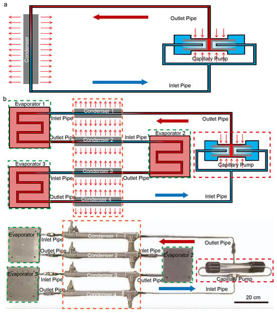
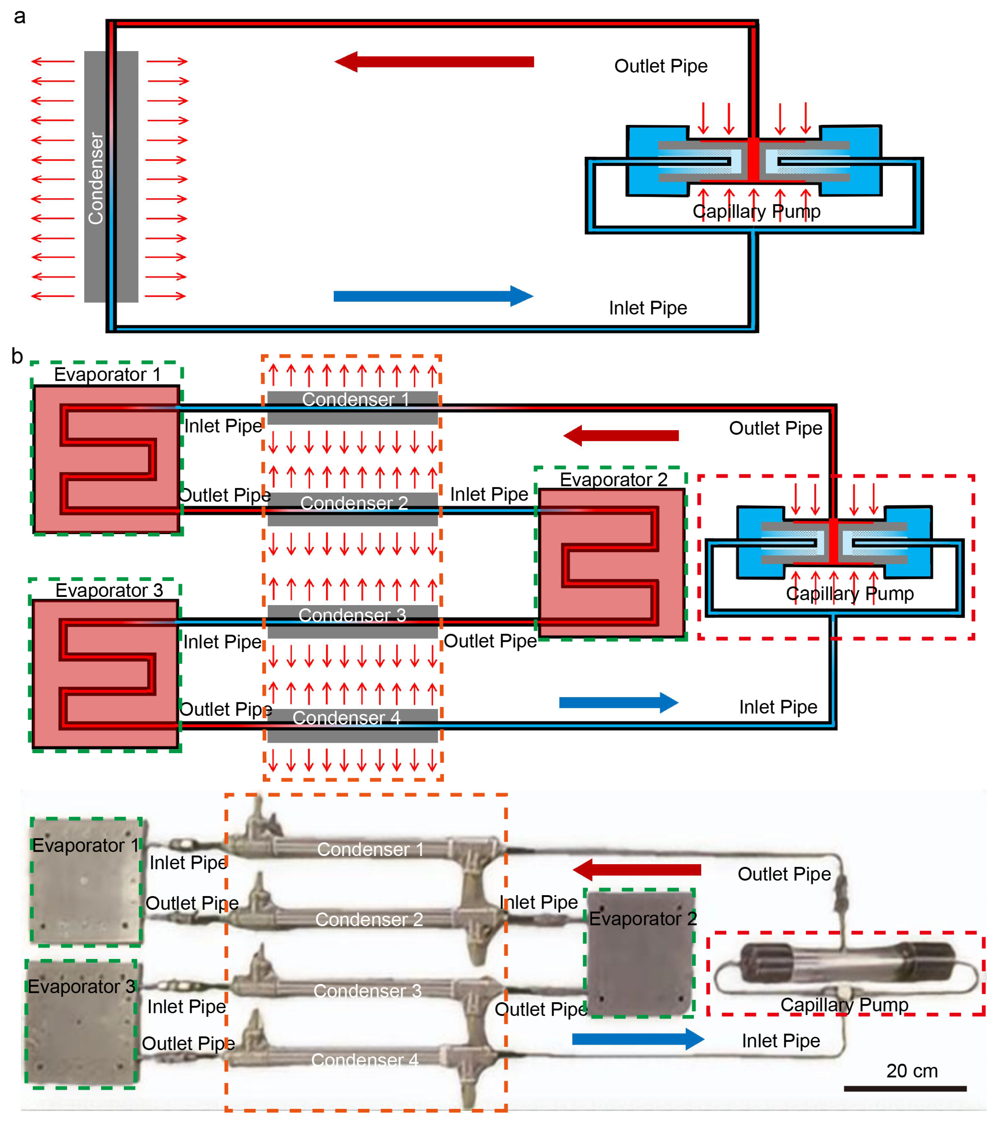
Unlike air and liquid cooling, the loop heat pipe (LHP) is a highly efficient phase-change heat transfer device. As shown in Figure 1a, the evaporator contains a built-in porous wick, which utilizes the capillary force generated by the phase change of the working fluid to achieve unidirectional circulation. This allows for remote heat transfer without the need for external power [21]. This advantage enables the separation of the evaporator and the condenser sections in LHP systems, facilitating flexible piping layouts and reducing spatial requirements [22], enabling it to couple multiple evaporators to form a multiple-evaporator loop heat pipe (ME-LHP).
Figure 1.
(a) Schematic diagram of the conventional loop heat pipe system. (b) Schematic and physical diagram of the DCCME-LHP system.
Theoretical research on ME-LHP began around 1988, and experimental verification started in 1992 [23]. In terms of structural design, existing studies have proposed dual-evaporator LHPs and successfully realized the startup of three-evaporator LHPs [24], verifying the feasibility of multi-evaporator structures [25]; for the multi-heat source management requirements of satellites, a dual-compensation chamber, dual-evaporator LHP architecture was designed and proposed [26,27,28,29]; meanwhile, a four-evaporator hybrid device combining the advantages of LHP and Capillary Pumped Loop (CPL) has also been developed [30]. In terms of heat transfer mechanisms, by comparing the thermal resistance and startup behavior of single- and dual-evaporator LHPs, the ability of multi-evaporator structures to achieve long-distance high-efficiency heat transfer has been confirmed [31]; existing research has also suppressed the imbalance of gas-liquid distribution by regulating compensation chamber parameters [32,33], and clarified the capillary limit characteristics and the negative influence of anti-gravity orientations in multi-evaporator/multi-condenser LHPs [34,35,36,37]. In terms of numerical simulation, the establishment of hydrodynamic models for ME-LHP has revealed the matching relationship between internal resistance and capillary driving force, as well as the influence laws of heat load and operating orientation [38]. In summary, existing multi-evaporator LHP research mostly focuses on parallel structures. Although the parallel structure has smaller flow resistance, it faces inherent challenges of complex piping and uneven flow distribution among branches (flow maldistribution). In contrast, the series (serial) structure has a simpler piping layout and can physically ensure that all heat sources obtain the same working fluid flow rate, greatly simplifying system control. However, the serial structure also brings severe challenges: the cumulative pressure drop of the multi-stage evaporators increases significantly, which places higher requirements on the driving capability of the capillary pump and the startup stability of the system.
In view of this, based on the working principle of LHPs [39], this study constructs a multi-evaporator dual compensation chamber loop heat pipe system (DCCME-LHP) by connecting flat-plate evaporators in series within the extended condensation section of the loop heat pipe, as shown in Figure 1b. In this system, the capillary driving force of the wick serves as the motive force for fluid flow, eliminating the need for a mechanical pump and thus requiring no extra power consumption [40]. We focus on the influence of the working fluid charge ratio on the system’s thermodynamic performance and systematically analyzing the mechanism of the time interval in suppressing temperature oscillations. Furthermore, under extreme heat load conditions, the coupling failure mechanism between the capillary pumping force and the cumulative pressure drop of the serial loop will be revealed. The results aim to provide experimental support for determining the stability boundaries and formulating operational strategies for passive multi-heat source cooling systems.
Unlike conventional loop heat pipe designs, this study proposes a DCCME-LHP configuration that effectively resolves the liquid-vapor distribution imbalance inherent in multi-evaporator systems. By implementing a step-by-step advancement of multiple condenser-evaporator units, the proposed system achieves a significantly higher heat-dissipation capacity (270 W) and superior long-distance transport stability compared to previous serial or parallel LHP architectures reported in the literature. Furthermore, this research identifies the coupled failure mechanism of liquid supply and pressure drop, providing a precise critical threshold. The proposed DCCME-LHP system particularly suitable for the thermal management of electric vehicles (EVs) and large-scale data centers, where efficient heat dissipation from distributed, multi-heat sources is a critical requirement. Furthermore, the system provides a robust and reliable technical path for the synchronized isothermal cooling of ensuring stable operation in confined and remote environments without the need for external power.
2. Design and Construction of the Experimental System
2.1. System Design
To achieve efficient collaborative heat dissipation for multi-heat sources, a multi-evaporator dual compensation chamber loop heat pipe system was constructed, the core structure of which is illustrated in Figure 1b. The system utilizes a capillary pump as the power core, integrated with key components including condensers 1–4, evaporators 1–3 connected in series via high-temperature resistant, and low-flow-resistance piping to form a closed-loop heat transfer circuit, creating an integrated assembly with both passive driving and multi-stage heat transfer functions. The core operational logic of the system relies on the phase-change driving force of the capillary pump to achieve working fluid circulation and heat transfer. The capillary pump absorbs heat at its heating surface, causing the internal liquid working fluid to undergo rapid and continuous phase change and generate a large volume of high-temperature, high-pressure vapor. This high-pressure vapor enters the loop through the vapor pipe to create forward thrust, precisely driving the subcooled liquid already condensed in condenser 1 to overcome pipeline resistance and flow steadily into the heat exchange channels of flat-plate evaporator 1. The liquid working fluid entering evaporator 1 makes full contact with the corresponding heat source, absorbs heat, and undergoes phase change again; the resulting secondary vapor further increases local loop pressure, continuously pushing the condensed liquid in condenser 2 toward evaporator 2. This process continues sequentially between evaporators 2 and 3, which not only achieves continuous, directional heat transfer across multi-heat sources but also drives the working fluid into a stable, pulsating advancement flow state, ensuring heat transfer efficiency. Finally, the terminal vapor generated by evaporator 3 carries the heat from all heat source stages into condenser 4, where it is fully condensed into liquid under the action of the cooling medium; the condensed liquid then returns to the compensation chamber (liquid reservoir) via the liquid pipe under the synergy of loop pressure difference and gravity, completing a full working fluid cycle. Detailed system parameters are listed in Table 1.
Table 1.
Structural parameters of the integrated system.
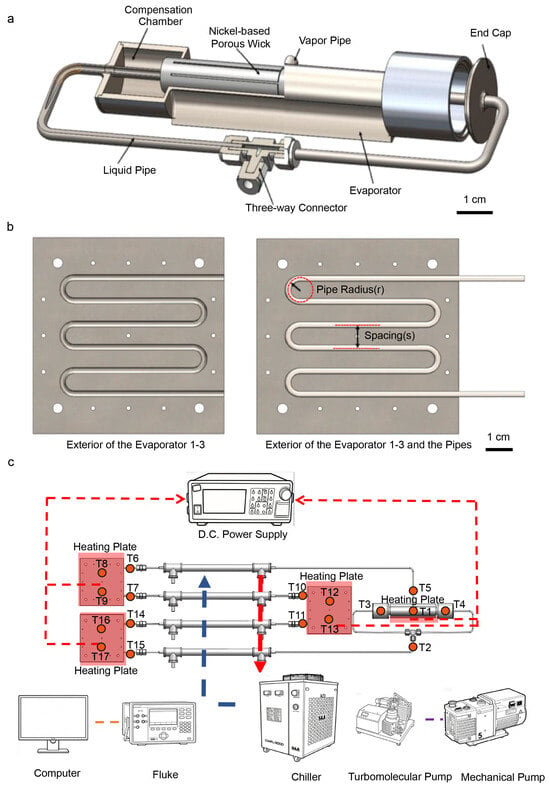
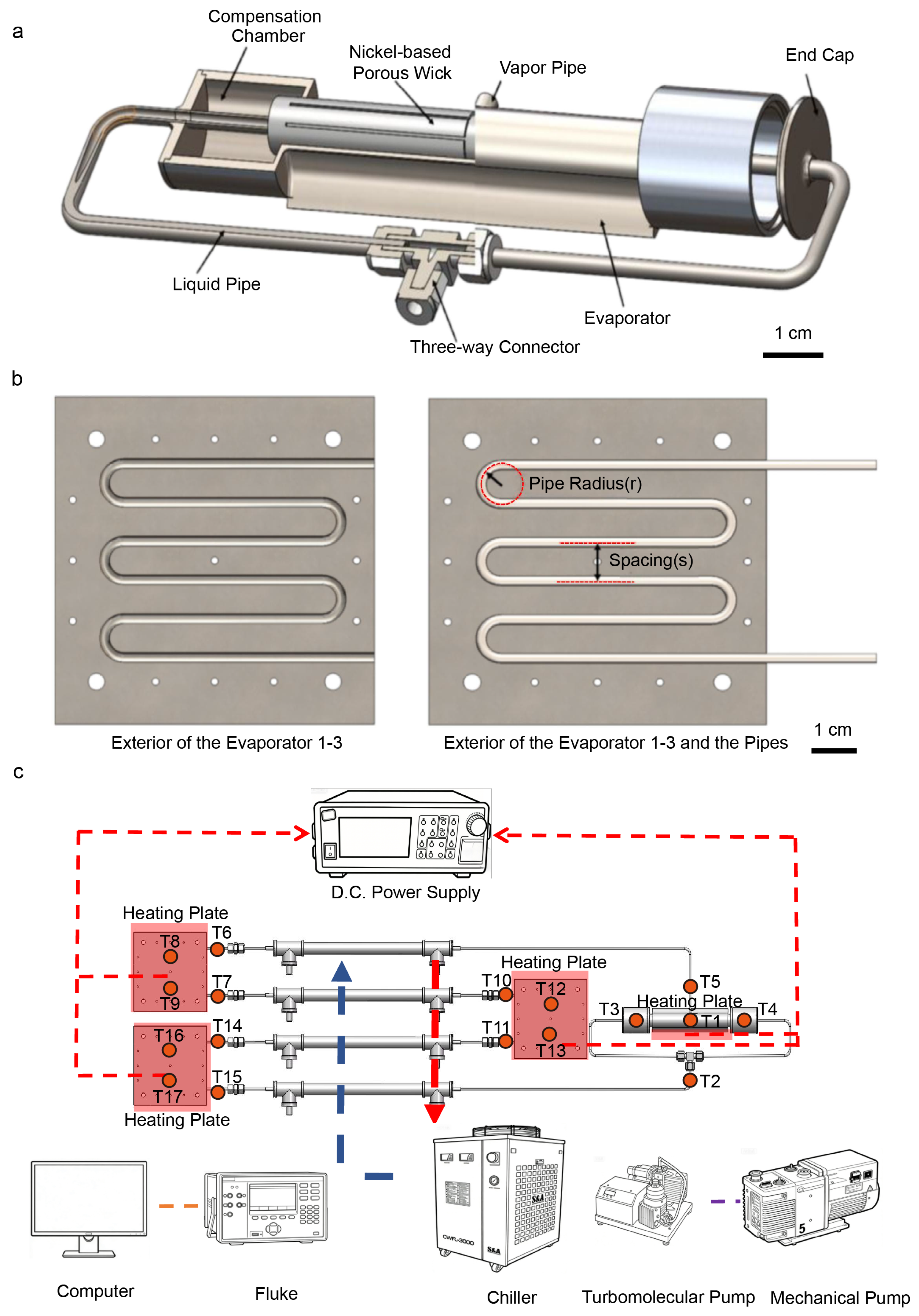
To enhance operational stability and heat transfer efficiency, the capillary pump adopts a targeted dual-liquid-line and dual compensation chamber structural design. The vapor pipe is located at the center of the evaporator to ensure smooth vapor discharge, while the liquid pipes are symmetrically distributed on both sides of the capillary pump to achieve uniform condensate return, forming an efficient vapor-liquid circulation loop. The main body of the capillary pump is constructed from corrosion-resistant and high-temperature-resistant stainless steel to adapt to various complex working environments. Its internal core is equipped with a nickel-based porous wick featuring a composite pore structure, a porosity of 74.07%, and an effective thermal conductivity of 2.734 W/(m·K), providing core support for the high-efficiency heat exchange of the capillary pump through its excellent structural and thermal properties. The specific structure of the capillary pump, as shown in Figure 2a, consists of the wick, evaporator, compensation chamber (reservoir), end cap, and vapor/liquid pipes, with all components working in coordination to ensure stable operation. Crucially, the bottom of the evaporator features a flat design to significantly increase the tightness of contact with the heat source surface, ensuring rapid and uniform heat conduction and further optimizing the heat exchange effect. Detailed technical parameters of the capillary pump are shown in Table 2.
Figure 2.
(a) Structural diagram of the dual compensation chamber capillary pump. (b) Structural diagram of the flat-plate evaporator. (c) Schematic diagram of the experimental system.
Table 2.
Structural parameters of the capillary pump.
To optimize heat transfer efficiency and structural stability, the evaporators utilize a sandwich structure design, the specific construction of which is shown in Figure 2b, comprising three key components: an upper cover plate, a lower cover plate, and a serpentine pipe. Both the upper and lower cover plates are made of 4 cm thick aluminum, which possesses excellent thermal conductivity and moderate structural strength to conduct heat rapidly while ensuring structural integrity; semi-circular serpentine grooves with a radius of 2 mm are machined into the surfaces of the plates to provide a precisely fitted space for the installation of the serpentine pipe. The middle layer of the sandwich structure is the core heat exchange element—a serpentine pipe made of stainless steel with an outer diameter (OD) of 4 mm and an inner diameter (ID) of 3 mm. The corrosion resistance of stainless steel allows for compatibility with various heat transfer media, while the serpentine design maximizes the heat exchange area to enhance efficiency. To ensure assembly sealing and firmness, the upper plate features pre-drilled bolt holes that align precisely with the threaded holes on the lower plate during assembly, achieving reliable fixation and sealing through bolt fastening. Simultaneously, thermal grease is applied within the serpentine grooves of both plates to effectively fill the micro-gaps between the pipe and the grooves, significantly enhancing the tightness of the fit between the serpentine pipe and the evaporator cover plates and further improving heat conduction efficiency. Detailed technical parameters of the evaporator can be found in the specific data in Table 3.
Table 3.
Structural parameters of the flat-plate evaporator.
2.2. Experimental Setup
To obtain the temperature response and steady-state performance under various conditions, a thermal experimental platform was constructed, as shown in Figure 2c. The platform primarily consists of three key modules: an adjustable D.C. power supply, a chiller, and a data collection system. The design of the simulated heat sources (Phlogopite heating plates, max power 1500 W, thickness 1 mm) is particularly critical, consisting of adjustable heat sources at the capillary pump and the three flat-plate evaporators. To guarantee the independence and controllability of each heat source and ensure precise heat load adjustment under different conditions, each heat source is independently powered by an adjustable D.C. power supply (MP-50100C, Dongguan Maisheng Power Supply Technology Co., Ltd., Dongguan, China, 0–50 V, 0–100 A). To further improve experimental accuracy, thermal grease (Qingmei QM850, Shanghai Zihong Electronics Co., Ltd., Shanghai, China, conductivity > 4.15 W/(m·K), range −50 to 200 °C) was applied uniformly at the contact interfaces between the simulated heat sources and the system to significantly reduce contact resistance by filling micro-gaps, ensuring efficient and stable heat transfer. Simultaneously, the capillary pump, evaporators, and vapor/liquid pipes were completely wrapped in insulation foam (aluminum silicate insulation cotton, thickness 2 mm, thermal conductivity 0.03 W/(m·K)) to effectively isolate the experimental system from environmental temperature fluctuations, thereby maximizing the authenticity and reliability of the data collected during actual operation. The cooling system utilizes a high-efficiency water-cooling module configuration, with shell-and-tube heat exchangers selected as the core condensing components, featuring specifically designed 16 mm cooling water channels and 4 mm tube grooves. Cooling water at 15 °C is supplied to the four condensers from an independent constant-temperature water tank (DC-2020, Ningbo Scientz Biotechnology Co., Ltd., Ningbo, China, range −20 to 100 °C, stability ± 0.05 °C), which maintains a constant cooling environment through its precise temperature control system to avoid fluctuations affecting the experimental results. The data acquisition system primarily records temperature and is equipped with a Fluke 2638A (Fluke Calibration, Fluke Testing Instruments (Shanghai) Co., Ltd., Shanghai, China, 22 analog channels, DCV accuracy 0.0024%, thermocouple precision 0.5 °C) logger to achieve real-time display and synchronous recording of thermocouple values. For temperature measurement, 17 K-type thermocouples (TT-K-36, Omega Engineering-Omiya Measurement Technology (Shanghai) Co., Ltd., Shanghai, China, accuracy ± 0.5 °C) were used; to ensure measurement precision, these thermocouples were securely attached to the external walls of the pipes and shells at various positions to guarantee tight contact and accurately capture temperature variations at key locations.
2.3. Experimental Procedure and Uncertainty Analysis
Once the experimental apparatus was fully assembled, performing evacuation and charging the working fluid according to the overall system design specifications became critical prerequisites for ensuring stable operation and reliable experimental data. To minimize the adverse impact of non-condensable gases—which tend to hinder the phase change and flow of the working fluid, thereby reducing heat exchange efficiency—a multi-stage evacuation strategy using a combination of a mechanical vacuum pump and an Edwards turbomolecular pump was employed. Through gradient decompression, the internal pressure was strictly maintained at Pa. Anhydrous ethanol was selected as the working fluid due to its moderate boiling point (78.3 °C at 101.325 kPa), high latent heat of vaporization (841 kJ/kg), and excellent heat transfer performance [36]. Its chemical stability and compatibility with stainless steel match the requirements of the experimental conditions [36]. The successful startup of the capillary pump is the core step in establishing internal circulation, laying the foundation for subsequent performance studies. To achieve a smooth startup, a gradient heat load is first applied to the evaporator of the capillary pump. Simultaneously, the phase change process and flow status of the working fluid within the loop are tracked in real-time via the thermocouple temperature feedback system to ensure the fluid successfully transitions from liquid to vapor and completes startup. Once stable circulation is established and the system operates steadily at the set power level, preset heat loads are applied to the remaining flat-plate evaporators. By comparing the operating parameters of the different evaporators, the overall heat transfer performance of the system is evaluated.
To ensure experimental rigor and data reproducibility, all tests were conducted in a dedicated thermal management laboratory maintained at a constant ambient temperature of 25 °C. Critical components, including the capillary pump, evaporators, and transport lines, were insulated with 2 mm thick aluminum silicate foam to minimize the impact of external thermal fluctuations. A standardized experimental protocol was implemented to maintain consistent initial conditions across different test runs: the system remained idle for at least 4 h prior to each session to achieve full thermal equilibrium with the environment, and the cooling water circulation (set at a constant 15 °C) was initiated 30 min before applying heat loads to establish a repeatable starting temperature. Under these controlled conditions, the system’s performance was systematically evaluated across an experimental matrix comprising three specific working fluid charge ratios: 65%, 75%, and 85%.
The experimental platform’s uncertainty analysis is influenced by both direct and indirect measurement errors, primarily arising from instrument precision, calibration errors, and measurement repeatability. Table 4 lists the uncertainties of the primary parameters involved in direct measurements and calculations. Based on the calculations, the errors for all measured parameters (such as heat load, temperature, etc.) have been determined, with the calculated parameters not exceeding 5%. This error range is within the acceptable threshold, ensuring the reliability of all measurement data in this study.
Table 4.
The uncertainty of direct and indirect measurement parameters.
3. Results and Discussion
3.1. Charge Ratio of Working Fluid
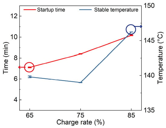
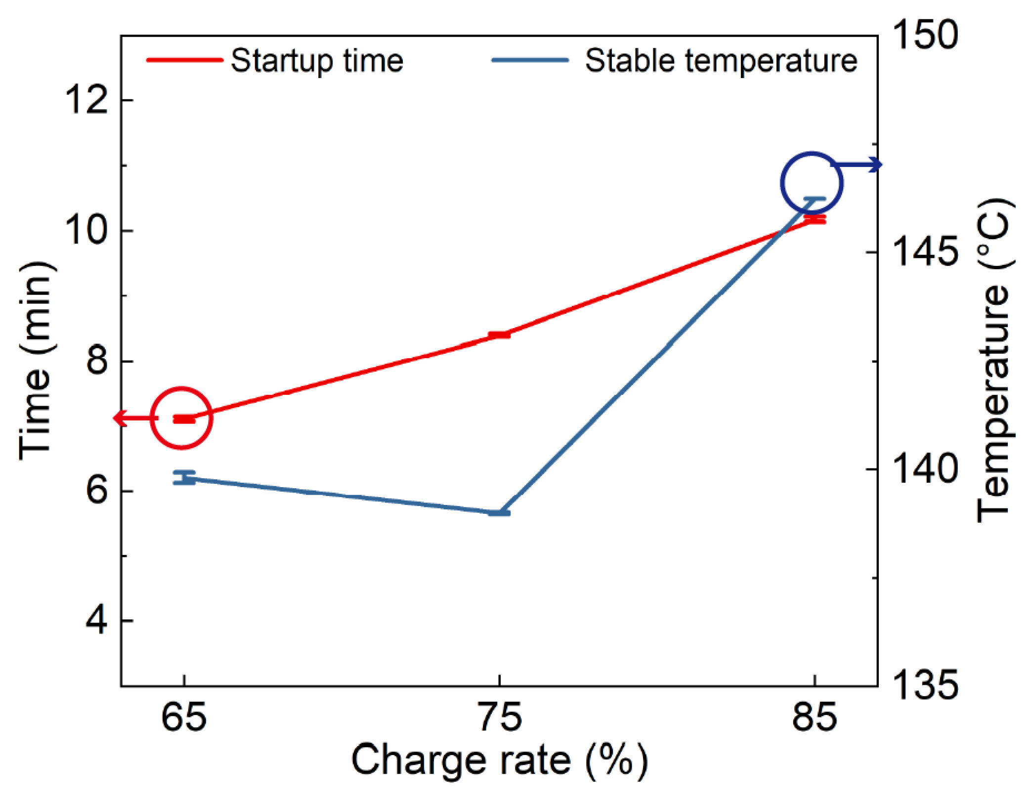
The charge ratio of the working fluid is the core parameter determining the spatial distribution of the fluid and the location of the phase-change interface. It is a prerequisite for achieving efficient phase-change heat transfer and a key factor directly affecting the heat transfer limit and overall operational stability [41]. As shown in Figure 3, results from the charge ratio experiments indicate that, as the ratio increases from 65% to 75% and further to 85%, the system startup time exhibits a continuous increasing trend. Meanwhile, the steady-state operating temperature shows a non-linear characteristic of first decreasing slightly and then increasing significantly; the 75% charge ratio yields the lowest steady-state temperature and optimal heat exchange efficiency, whereas the 85% case results in the highest temperature and a significant attenuation of heat transfer performance.The mechanism behind this phenomenon is closely related to the fluid distribution and phase-change cycle characteristics under different charge ratios. When the charge ratio is below 75%, the insufficient liquid inventory leads to inadequate wetting of the capillary wick within the evaporator and poor reliability of the liquid supply in the return loop. This results in incomplete phase change and higher equivalent thermal resistance, which adversely affects the heat transfer efficiency and startup response. At a charge ratio of 75%, the working fluid is uniformly distributed between the wick and the various flat-plate evaporators; the liquid return loop operates stably, and the vapor-liquid two-phase circulation is smooth. This allows the phase-change heat transfer potential to be fully utilized, achieving the lowest steady-state temperature while maintaining good startup characteristics. Conversely, when the charge ratio exceeds 85%, excess liquid occupies the effective condensation space and vapor channels, significantly increasing vapor flow resistance. The vapor driving force is then consumed by the increased system pressure drop, requiring the system to operate at a higher saturation pressure (and a corresponding higher saturation temperature) to maintain circulation, which prolongs the startup process and significantly raises the steady-state temperature. In summary, 75% is the optimal charge ratio for this system, achieving the best balance between startup response and steady-state thermal performance. Consequently, to ensure consistency and comparability of the experimental data, all subsequent performance tests were conducted with a 75% charge ratio (see Supplementary Figure S1 for details on charging ratio tests).
Figure 3.
Startup time vs. average steady-state temperature under different charge ratios.
3.2. Influence of Time Interval on Startup and Operational Stability
The time interval (the delay between the activation of the capillary pump and the simultaneous activation of evaporators 1–3) is a critical control strategy for the cooperative operation of multi-evaporator systems. This section investigates the influence of time intervals (1–16 min) on temperature oscillation, startup response, and steady-state distribution at a 75% charge ratio and fixed heat load (90 W for the capillary pump, 50 W for each evaporator).
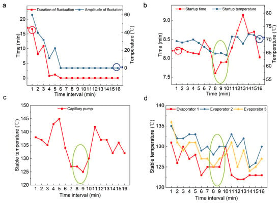
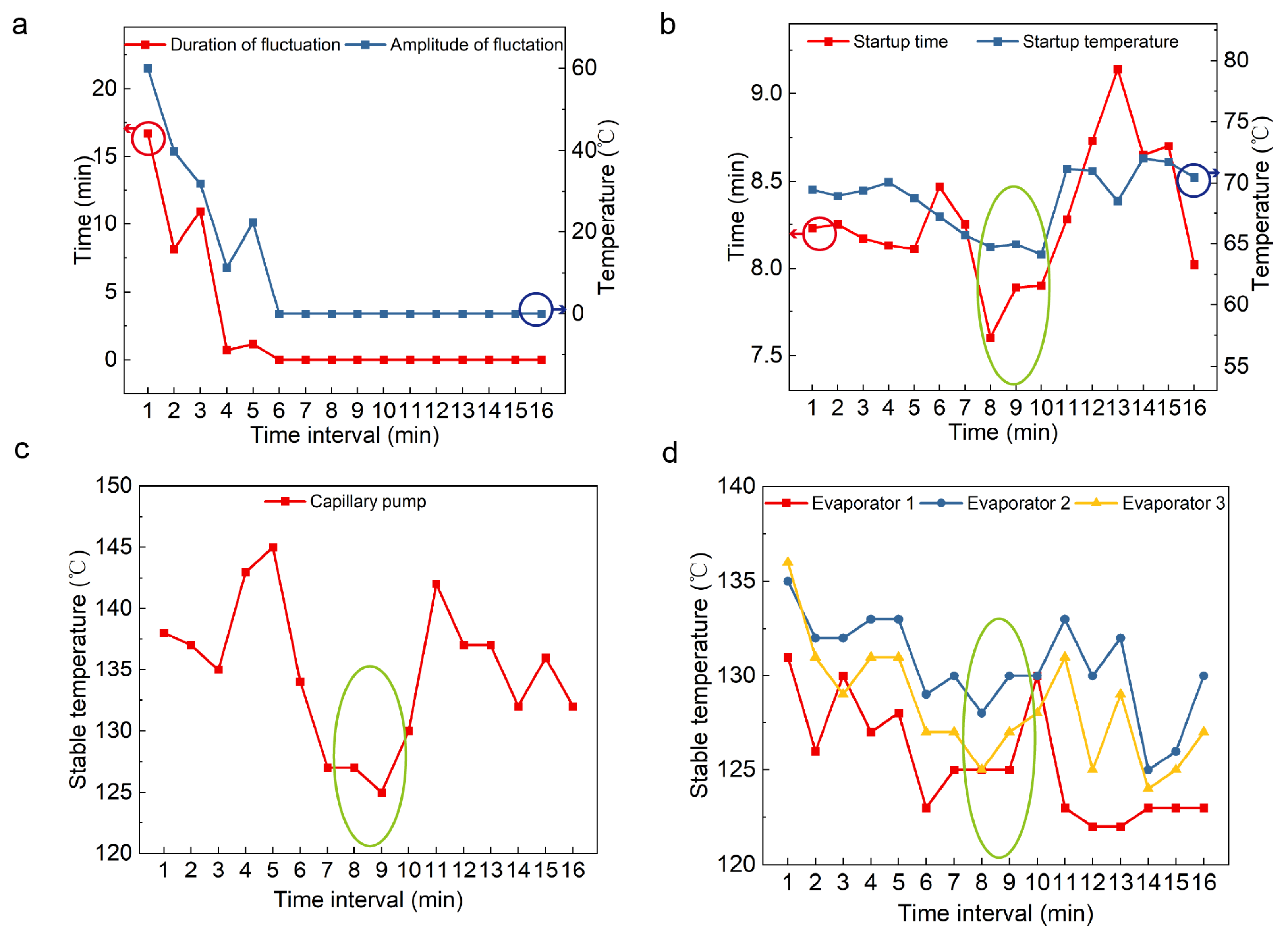
Temperature oscillation is evaluated by two key metrics: oscillation amplitude (the peak-to-valley temperature difference during the unstable phase) and oscillation duration (from the onset of oscillation until the amplitude decays to a stable threshold). As shown in Figure 4a, significant oscillations occur at intervals of 1–3 min, with amplitudes reaching dozens of degrees and durations lasting 8–17 min. This occurs because short intervals result in insufficient preheating of the capillary pump; the vapor driving force is not fully established, leading to a lack of overall driving power. In a multi-stage serial system, this easily forms slug flow or unstable gas-liquid advancement, manifesting as high amplitudes and long durations. As the interval increases to 4–6 min, the duration rapidly decreases toward zero. Beyond 6 min, the system enters a stable operating zone with minimal and constant oscillation amplitudes. In this regime, the preheating and vapor driving force are better established, leading to thorough liquid discharge from the condensers and effective fluid redistribution, which suppresses vapor channel blockage and enables a continuous two-phase cycle.
Figure 4.
(a) Oscillation duration vs. amplitude; (b) startup time vs. temperature for the capillary pump; (c) steady-state temperature of the capillary pump; (d) steady-state temperatures of evaporators 1–3.
The startup and steady-state performance of the capillary pump as a function of the time interval are shown in Figure 4b,c. Startup time generally fluctuates within a narrow range (8–9 min), with an optimal window identified at 8–10 min, where both startup time and startup temperature are minimized. At intervals of 12–14 min, these values increase significantly. An appropriate interval allows for sufficient preheating to trigger a stable cycle at a lower temperature, while an excessive interval leads to over-condensation, where accumulated liquid in the condenser and piping increases the pressure drop, requiring a higher saturation pressure to drive the loop. Steady-state temperatures fluctuate between 125 and 145 °C, also reaching a minimum at the 8–10 min interval.
For the flat-plate evaporators, the steady-state temperatures (120–135 °C) also fluctuate slightly with the interval, as shown in Figure 4d. Evaporator 2 consistently shows the highest temperature, while evaporator 1 is the lowest. At short intervals, incomplete fluid redistribution causes liquid slugs and channel blockage, leading to uneven supply and temperature fluctuations. At the optimal interval (8–10 min), the stable vapor driving force ensures continuous two-phase supply and a stable evaporation interface for the evaporators (see Supplementary Figure S2 for details on the temperature curves of the system time interval on startup and operational stability).
3.3. Heat Transfer Limit and Coupled Failure Mechanism Analysis
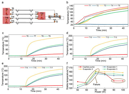
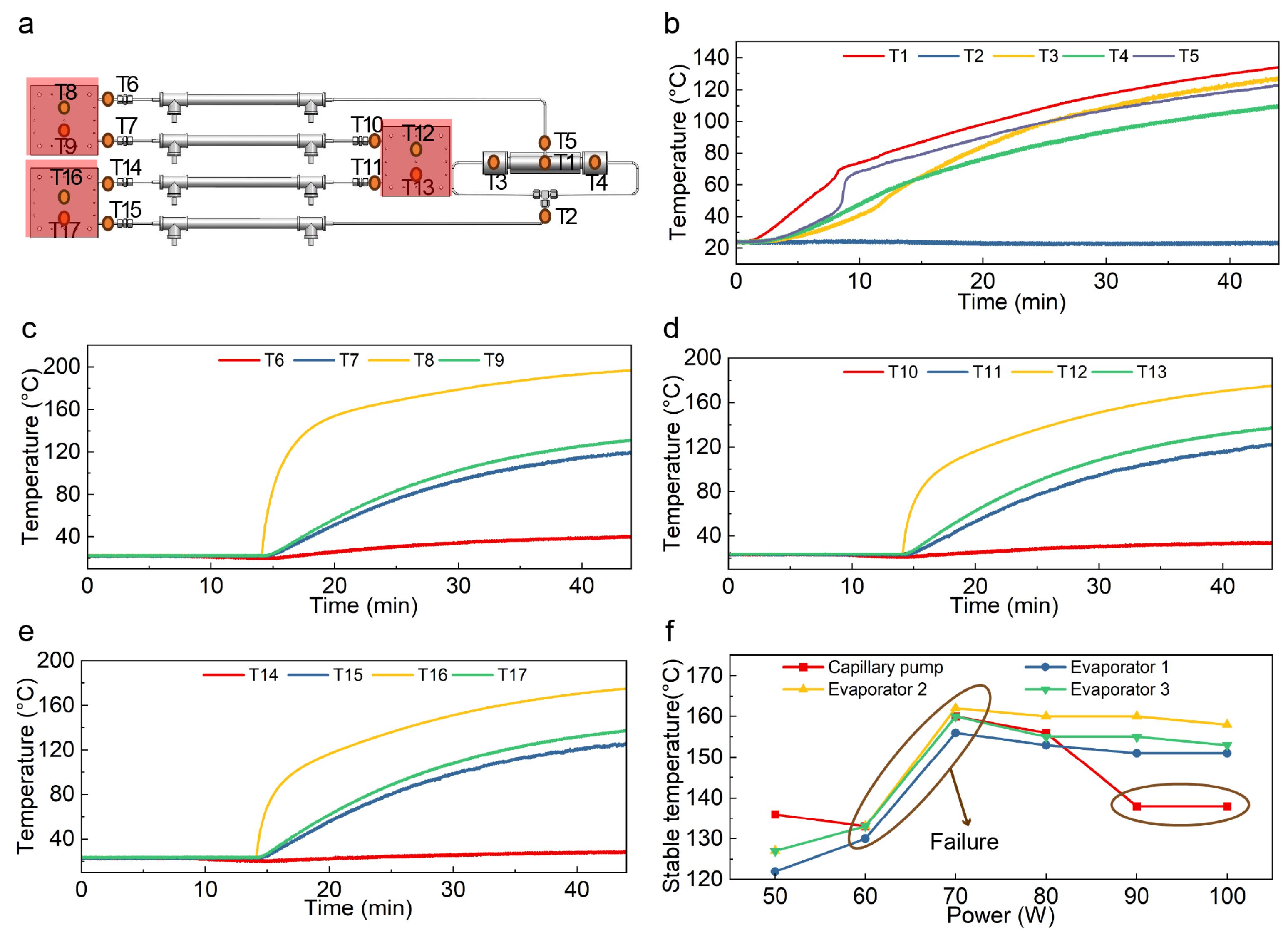
To determine the thermal boundaries, the system was tested under extreme power levels at the optimal charge ratio (75%) and interval (8–10 min). The system’s safety and stability were verified at a total heat load of 270 W (90 W for the capillary pump and 60 W for each evaporator). As shown in Figure 5b, the capillary pump completes startup at 8.4 min, evidenced by a sharp temperature rise at T1 (capillary pump) and T5 (vapor pipe), indicating that saturated vapor has entered the loop. After startup, temperatures rise smoothly without severe periodic oscillations. T2 (liquid return) remains low, indicating effective condensation and reflux. Figure 5c–e show that the evaporator temperatures (T8, T12, T16) surge to a plateau (180–200 °C) upon loading. Significant temperature stratification and localized hotspots are observed. The mechanism involves a “relay-style” vapor drive between evaporators; however, as the load approaches the limit, the capillary pumping capacity cannot match the evaporation demand due to the cumulative pressure drop. Intermittent dry-out occurs, causing the temperature rise. Although the system maintains circulation at 270 W, the localized high temperatures indicate it is nearing its heat transfer limit.
Figure 5.
(a) Thermocouple layout; (b) capillary pump temperature response; (c–e) evaporators 1–3 temperature response; (f) steady-state temperatures vs. power.
The effect of heat load variations is shown in Figure 5f. As the load per evaporator increases from 50 W to 60 W, temperatures rise gradually. At a heat load of 70 W, a temperature jump occurs, signaling system failure. When the load reaches 80–100 W, the capillary pump temperature actually drops while the evaporators remain at high temperatures. This is a characteristic failure mode: the cumulative pressure drop exceeds the capillary limit, leading to a drop in flow rate. The continuous heat input keeps the evaporators hot, but the reduced circulation and localized cooling at the pump result in a temperature decrease at the capillary pump end (see Supplementary Figure S3 for details on power tests).
In summary, the maximum heat dissipation power is 270 W, and the critical failure threshold for a single flat-plate evaporator is approximately 70 W. This clarifies the relay-style heat transfer mechanism and the coupled failure mode of insufficient liquid supply and cumulative pressure drop.
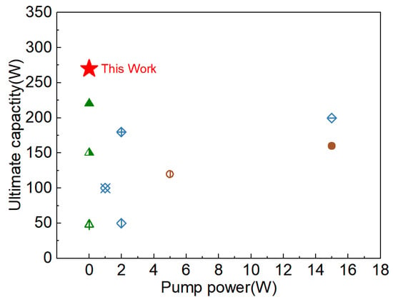
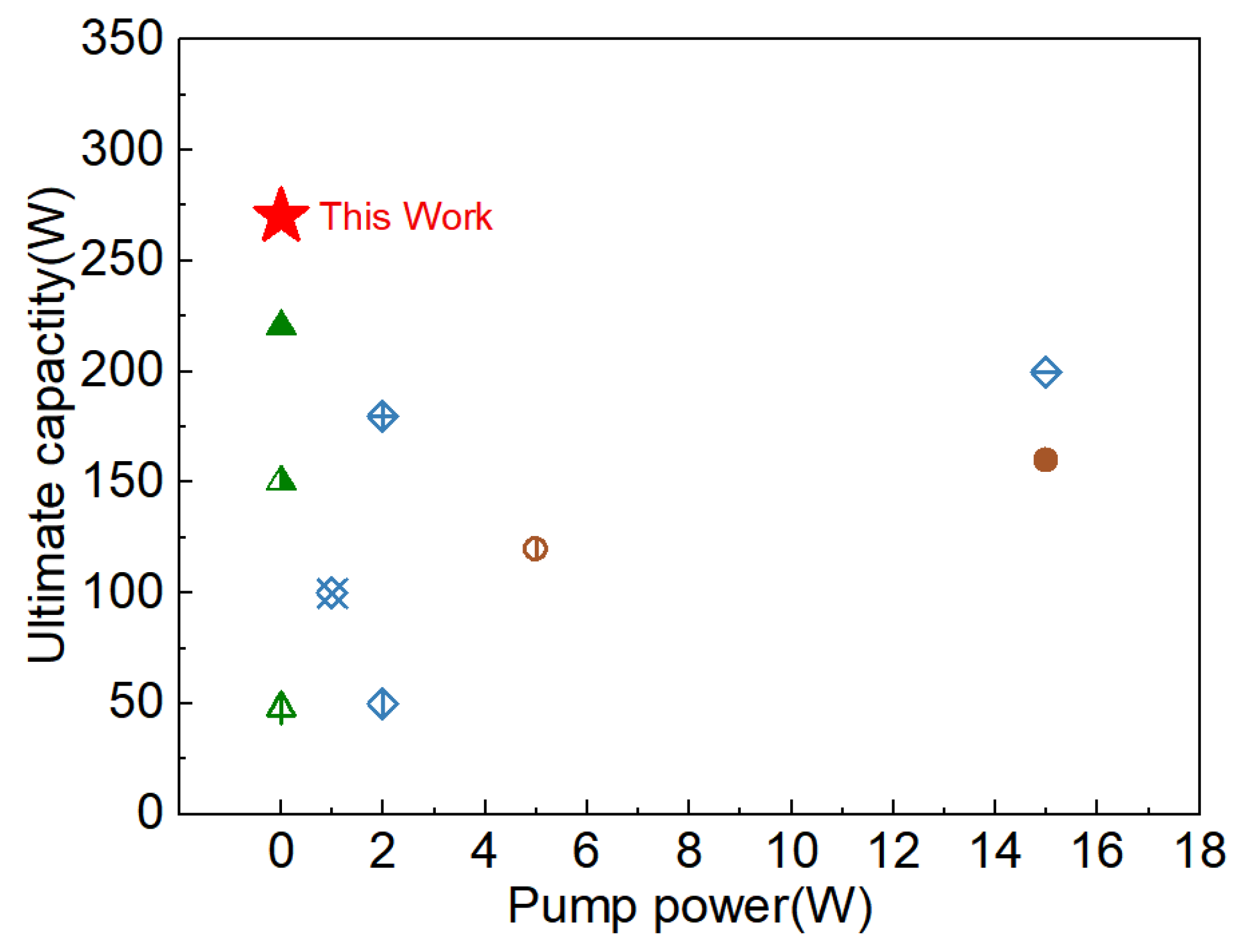
To provide a direct comparison of our DCCME-LHP’s competitive advantages relative to comparable thermal management technologies, Figure 6 summarizes a comprehensive capacity-power map that incorporates pumping power and ultimate heat-dissipation capacity. From the perspective of system-level performance optimization, a lower input pumping power combined with a higher ultimate heat-dissipation capacity indicated superior efficiency and cooling capability. Among self-driven cooling devices, the present work employed a capillary-driven mechanism and a coordinated design of the capillary pump and three evaporators, achieving an experimentally validated maximum heat-dissipation capacity of 270 W, which is substantially higher than that reported in related studies.
Figure 6.
Comparative analysis of pumping power consumption and ultimate performance limits reported in previous studies [29,37,42,43,44,45,46,47,48].
4. Conclusions
In this paper, a systematic experimental study was conducted on a DCCME-LHP system for multi-heat sources. By investigating the effects of working fluid charge ratio, time interval, and heat load, the system’s performance, optimal operating boundaries, and failure mechanisms were clarified. The specific conclusions are as follows:
- (1)
- The optimal working fluid charge ratio is . This balance minimizes flow resistance while maximizing capillary driving force and heat transfer efficiency.
- (2)
- The ideal startup time interval is 8–10 min, which ensures sufficient condensation and reflux for stable system initialization.
- (3)
- Under optimized conditions, the system stably sustains a total heat load of 270 W with uniform heat transfer and no pressure mutations.
- (4)
- The stable operation limit for a single-stage evaporator is 70 W. Exceeding this threshold leads to heat transfer failure; thus, engineering designs should stay below this limit.
Supplementary Materials
The following supporting information can be downloaded at: https://www.mdpi.com/article/10.3390/eng7020084/s1, Figure S1. Temperature curves of the system at varying charging ratios. (1) 65%, (2) 75%, (3) 85%; Figure S2. Temperature curves of the system time interval (1–16 min) on startup and operational stability; Figure S3. Steady-state temperatures vs. power. (1) 50 W, (2) 60 W, (3) 70 W, (4) 80 W, (5) 90 W, (6) 100 W.
Author Contributions
D.H.: conceptualization, methodology, validation, formal analysis, investigation, writing—original draft, writing—review and editing. Y.Z.: validation, formal analysis, investigation, visualization, writing—review and editing, funding acquisition. H.L.: writing—review and editing, supervision. C.G.: resources, supervision, writing—review and editing, funding acquisition. All authors have read and agreed to the published version of the manuscript.
Funding
The authors gratefully acknowledge financial support from the Key Research and Development Program of Shandong Province (No. 2022SFGC0501), the Shenzhen Science and Technology Program (International Cooperation Research, No. GJHZ20240218113407015), and the Shenzhen Fundamental Research Program (Natural Science Foundation, No. JCYJ20240813175900001).
Data Availability Statement
The raw data supporting the conclusions of this article will be made available by the authors on request.
Acknowledgments
The authors are grateful for the support by Centre for Omniscale Thermal Management and Comprehensive Energy Utilisation (OTM-EU). The authors also express their sincere appreciation to the editor and referees for their valuable time and efforts on our manuscript.
Conflicts of Interest
The authors declare that they have no known competing financial interests or personal relationships that could have appeared to influence the work reported in this paper.
Abbreviations
The following abbreviations are used in this manuscript:
| CPL | Capillary Pumped Loop |
| D | Diameter |
| DCCME-LHP | Dual Compensation Chamber Multi-evaporator Loop Heat Pipe system |
| EVs | Electric Vehicles |
| H | High |
| ID | Inner Diameter |
| L | Length |
| LHP | Loop Heat Pipe |
| ME-LHP | Multi-evaporator Loop Heat Pipe |
| OD | Outer Diameter |
| W | Wide |
References
- Zhang, G.; Kandlikar, S.G. A critical review of cooling techniques in proton exchange membrane fuel cell stacks. Int. J. Hydrogen Energy 2012, 37, 2412–2429. [Google Scholar] [CrossRef] [Scilit]
- Alkrush, A.A.; Salem, M.S.; Abdelrehim, O.; Hegazi, A. Data centers cooling: A critical review of techniques, challenges, and energy saving solutions. Int. J. Refrig. 2024, 160, 246–262. [Google Scholar] [CrossRef] [Scilit]
- Yang, S.; Bryant, A.; Mawby, P.; Xiang, D.; Ran, L.; Tavner, P. An Industry-Based Survey of Reliability in Power Electronic Converters. IEEE Trans. Ind. Appl. 2011, 47, 1441–1451. [Google Scholar] [CrossRef] [Scilit]
- Al-Sarkhi, A.; Abu-Nada, E.; Akash, B.; Jaber, J. Numerical Investigation of Shrouded Fin Array Under Combined Free and Forced Convection. Int. Commun. Heat Mass Transf. 2003, 30, 435–444. [Google Scholar] [CrossRef] [Scilit]
- Hua, W.; Zhang, L.; Zhang, X. Research on passive cooling of electronic chips based on PCM: A review. J. Mol. Liq. 2021, 340, 117183. [Google Scholar] [CrossRef] [Scilit]
- Govindasamy, M.; Ezhumalai, M.; Dhairiyasamy, R.; Varshney, D.; Singh, S.; Gabiriel, D. Comprehensive Investigation into the Thermal Performance of Nanofluid-Enhanced Heat Pipes for Advanced Thermal Management Systems. Eng 2025, 6, 55. [Google Scholar] [CrossRef] [Scilit]
- Virmani, D.; Chatterjee, B. Thermal Management Challenges in 2.5D and 3D Chiplet Integration: A Review on Architecture–Cooling Co-Design. Eng 2025, 6, 373. [Google Scholar] [CrossRef] [Scilit]
- Yang, K.S.; Li, S.L.; Chen, I.Y.; Chien, K.H.; Hu, R.; Wang, C.C. An experimental investigation of air cooling thermal module using various enhancements at low Reynolds number region. Int. J. Heat Mass Transf. 2010, 53, 5675–5681. [Google Scholar] [CrossRef] [Scilit]
- Ni, J.; Bai, X. A review of air conditioning energy performance in data centers. Renew. Sustain. Energy Rev. 2017, 67, 625–640. [Google Scholar] [CrossRef] [Scilit]
- Fang, G.; Yuan, W.; Yan, Z.; Sun, Y.; Tang, Y. Thermal management integrated with three-dimensional heat pipes for air-cooled permanent magnet synchronous motor. Appl. Therm. Eng. 2019, 152, 594–604. [Google Scholar] [CrossRef] [Scilit]
- Agostini, B.; Fabbri, M.; Park, J.E.; Wojtan, L.; Thome, J.R.; Michel, B. State of the Art of High Heat Flux Cooling Technologies. Heat Transf. Eng. 2007, 28, 258–281. [Google Scholar] [CrossRef] [Scilit]
- Lu, T. Thermal management of high power electronics with phase change cooling. Int. J. Heat Mass Transf. 2000, 43, 2245–2256. [Google Scholar] [CrossRef] [Scilit]
- Pourfattah, F.; Sabzpooshani, M. Thermal management of a power electronic module employing a novel multi-micro nozzle liquid-based cooling system: A numerical study. Int. J. Heat Mass Transf. 2020, 147, 118928. [Google Scholar] [CrossRef] [Scilit]
- Hnayno, M.; Chehade, A.; Klaba, H.; Bauduin, H.; Polidori, G.; Maalouf, C. Performance analysis of new liquid cooling topology and its impact on data centres. Appl. Therm. Eng. 2022, 213, 118733. [Google Scholar] [CrossRef] [Scilit]
- Papis-Frączek, K.; Sornek, K. A Review on Heat Extraction Devices for CPVT Systems with Active Liquid Cooling. Energies 2022, 15, 6123. [Google Scholar] [CrossRef] [Scilit]
- Shahi, P.; Mathew, A.; Akash; Saini, S.; Bansode, P.; Kasukurthy, R.; Agonafer, D. Assessment of Reliability Enhancement in High-Power Cpus and Gpus Using Dynamic Direct-to-Chip Liquid Cooling. J. Enhanc. Heat Transf. 2022, 29, 1–13. [Google Scholar] [CrossRef] [Scilit]
- Jung, K.W.; Kharangate, C.R.; Lee, H.; Palko, J.; Zhou, F.; Asheghi, M.; Dede, E.M.; Goodson, K.E. Embedded cooling with 3D manifold for vehicle power electronics application: Single-phase thermal-fluid performance. Int. J. Heat Mass Transf. 2019, 130, 1108–1119. [Google Scholar] [CrossRef] [Scilit]
- Singhal, V.; Garimella, S.V.; Raman, A. Microscale pumping technologies for microchannel cooling systems. Appl. Mech. Rev. 2004, 57, 191–221. [Google Scholar] [CrossRef] [Scilit]
- Arun Shankar, V.K.; Umashankar, S.; Paramasivam, S.; Hanigovszki, N. A comprehensive review on energy efficiency enhancement initiatives in centrifugal pumping system. Appl. Energy 2016, 181, 495–513. [Google Scholar] [CrossRef] [Scilit]
- Chiara, F.; Canova, M. A review of energy consumption, management, and recovery in automotive systems, with considerations of future trends. Proc. Inst. Mech. Eng. Part D J. Automob. Eng. 2013, 227, 914–936. [Google Scholar] [CrossRef] [Scilit]
- Launay, S.; Sartre, V.; Bonjour, J. Parametric analysis of loop heat pipe operation: A literature review. Int. J. Therm. Sci. 2007, 46, 621–636. [Google Scholar] [CrossRef] [Scilit]
- Ambirajan, A.; Adoni, A.A.; Vaidya, J.S.; Rajendran, A.A.; Kumar, D.; Dutta, P. Loop Heat Pipes: A Review of Fundamentals, Operation, and Design. Heat Transf. Eng. 2012, 33, 387–405. [Google Scholar] [CrossRef] [Scilit]
- Goncharov, K.A. Multi-evaporator loop heat pipe. In Proceedings of the AIP Conference Proceedings; AIP: Melville, NY, USA, 2000; Volume 504, pp. 778–784. [Google Scholar] [CrossRef] [Scilit]
- Qu, Y.; Zhou, D.; Qiao, S.; Zhou, K.; Tian, Y. Experimental study on the startup performance of dual-evaporator loop heat pipes. Int. J. Therm. Sci. 2021, 170, 107168. [Google Scholar] [CrossRef] [Scilit]
- Goncharov, K.; Golovin, O.; Kolesnikov, V. Loop Heat Pipe with Several Evaporators. In Proceedings of the SAE Technical Paper Series; SAE International: Warrendale, PA, USA, 2000; Volume 1. [Google Scholar] [CrossRef] [Scilit]
- Long, J.B.; Ochterbeck, J.M. Response of Loop Heat Pipes to Transient Heat Loads. In Proceedings of the ASME 1999 International Mechanical Engineering Congress and Exposition, Nashville, TN, USA, 14–19 November 1999; The American Society of Mechanical Engineers: New York, NY, USA, 1999; Volume 4. [Google Scholar] [CrossRef] [Scilit]
- Wang, T.; Zhao, J.; Liu, W.; Ma, L.; Liu, Z. Experimental investigation for the loop heat pipe with a bifacial flat evaporator. Int. J. Therm. Sci. 2024, 200, 108989. [Google Scholar] [CrossRef] [Scilit]
- He, S.; Ma, Z.; Deng, W.; Zhang, Z.; Guo, Z.; Liu, W.; Liu, Z. Experimental investigation on the start-up performance of a novel flat loop heat pipe with dual evaporators. Energy Rep. 2022, 8, 7500–7507. [Google Scholar] [CrossRef] [Scilit]
- He, X.; Yan, W.; Wang, S. Study on heat transfer characteristics of a dual-evaporator ultra-thin loop heat pipe for laptop cooling. Appl. Therm. Eng. 2024, 241, 122395. [Google Scholar] [CrossRef] [Scilit]
- Bugby, D.; Miller, T.; Baker, J. Multi-Evaporator Two-Phase Loop Cooling System. In Proceedings of the 4th International Energy Conversion Engineering Conference and Exhibit (IECEC); American Institute of Aeronautics and Astronautics: Reston, VA, USA, 2006. [Google Scholar] [CrossRef] [Scilit]
- Kozmine, D.; Goncharov, K.; Nikitkin, M.; Maidanik, Y.F.; Fershtater, Y.G.; Fiodor, S. Loop Heat Pipes for Space Mission Mars 96. In Proceedings of the SAE Technical Paper Series; SAE International: Warrendale, PA, USA, 1996; Volume 1. [Google Scholar] [CrossRef] [Scilit]
- Lin, G.; Zhang, H.; Shao, X.; Cao, J.; Ding, T.; Miao, J. Development and Test Results of a Dual Compensation Chamber Loop Heat Pipe. J. Thermophys. Heat Transf. 2006, 20, 825–834. [Google Scholar] [CrossRef] [Scilit]
- Zhang, Y.; Wang, G.; Wang, X.; Wang, J.; Xue, H.; Luan, T. Performance and energy consumption study of a dual-evaporator loop heat pipe for chip-level cooling. Appl. Therm. Eng. 2025, 258, 124757. [Google Scholar] [CrossRef] [Scilit]
- Nagano, H.; Ku, J. Capillary Limit of a Multiple-Evaporator and Multiple-Condenser Miniature Loop Heat Pipe. J. Thermophys. Heat Transf. 2007, 21, 694–701. [Google Scholar] [CrossRef] [Scilit]
- Chang, X.; Watanabe, N.; Nagano, H. Visualization study of a loop heat pipe with two evaporators and one condenser under gravity-assisted condition. Int. J. Heat Mass Transf. 2019, 135, 378–391. [Google Scholar] [CrossRef] [Scilit]
- Chang, X.; Watanabe, N.; Nagai, H.; Nagano, H. Visualization of thermo-fluid behavior of loop heat pipe with two evaporators and one condenser under various orientation with even heat loads. Int. J. Heat Mass Transf. 2022, 198, 123397. [Google Scholar] [CrossRef] [Scilit]
- Chang, X.; Watanabe, N.; Nagai, H.; Nagano, H. Visualization of thermo-fluid behavior of loop heat pipe with two evaporators and one condenser under various orientations with uneven heat loads. Int. J. Heat Mass Transf. 2024, 221, 125054. [Google Scholar] [CrossRef] [Scilit]
- Maydanik, Y.F. Development and Test Results of a Multi-Evaporator-Condenser Loop Heat Pipe. In Proceedings of the AIP Conference Proceedings; AIP: Melville, NY, USA, 2003; Volume 654, pp. 42–48. [Google Scholar] [CrossRef] [Scilit]
- Kaya, T.; Goldak, J. Numerical analysis of heat and mass transfer in the capillary structure of a loop heat pipe. Int. J. Heat Mass Transf. 2006, 49, 3211–3220. [Google Scholar] [CrossRef] [Scilit]
- Liu, X.; Liu, H.; Zhao, X.; Han, Z.; Cui, Y.; Yu, M. A novel neural network and grey correlation analysis method for computation of the heat transfer limit of a loop heat pipe (LHP). Energy 2022, 259, 124830. [Google Scholar] [CrossRef] [Scilit]
- Liu, M.; Ning, W.; Yang, J.; Zhang, Y.; Han, Z.; Meng, G.; Guo, C.; Lin, H.; Jia, B. High-performance multi-morphology porous wick fabricated using a composite pore former. Int. Commun. Heat Mass Transf. 2023, 148, 107019. [Google Scholar] [CrossRef] [Scilit]
- Ku, J.; Ottenstein, L.; Douglas, D.; Hoang, T. Multi-Evaporator Miniature Loop Heat Pipe for Small Spacecraft Thermal Control, Part I: New Technologies and Validation Approach. In Proceedings of the 48th AIAA Aerospace Sciences Meeting Including the New Horizons Forum and Aerospace Exposition, Orlando, FL, USA, 4–7 January 2010. [Google Scholar] [CrossRef] [Scilit]
- Yang, X.; Liu, J.; Wang, G.; Wei, J. Experimental study of mechanical-capillary driven phase-change loop for heat dissipation of electronic devices and batteries. Appl. Therm. Eng. 2022, 210, 118350. [Google Scholar] [CrossRef] [Scilit]
- Liu, J.; Pei, N.-Q.; Guo, K.-H.; He, Z.-H.; Li, T.-X. Experimental investigation on a mechanically pumped two-phase cooling loop with dual-evaporator. Int. J. Refrig. 2008, 31, 1176–1182. [Google Scholar] [CrossRef] [Scilit]
- Kim, Y.J.; Joshi, Y.K.; Fedorov, A.G. An absorption based miniature heat pump system for electronics cooling. Int. J. Refrig. 2008, 31, 23–33. [Google Scholar] [CrossRef] [Scilit]
- Liu, J.; Lv, M.; Zhang, S.X.; Guo, K.-H.; He, Z.-H.; Li, T.-X. Experimental investigation on start-up of mechanically pumped cooling loop. Energy Convers. Manag. 2008, 49, 2595–2601. [Google Scholar] [CrossRef] [Scilit]
- Bazzo, E.; Riehl, R. Operation characteristics of a small-scale capillary pumped loop. Appl. Therm. Eng. 2003, 23, 687–705. [Google Scholar] [CrossRef] [Scilit]
- Jiang, C.; Liu, W.; Wang, H.; Wang, D.; Yang, J.; Li, J.; Liu, Z. Experimental investigation of pump-assisted capillary phase change loop. Appl. Therm. Eng. 2014, 71, 581–588. [Google Scholar] [CrossRef] [Scilit]

Disclaimer/Publisher’s Note: The statements, opinions and data contained in all publications are solely those of the individual author(s) and contributor(s) and not of MDPI and/or the editor(s). MDPI and/or the editor(s) disclaim responsibility for any injury to people or property resulting from any ideas, methods, instructions or products referred to in the content. |
© 2026 by the authors. Licensee MDPI, Basel, Switzerland. This article is an open access article distributed under the terms and conditions of the Creative Commons Attribution (CC BY) license.