


Abstract
This study presents a structural strength analysis of a metal elevator bucket equipped with a hinged movable bottom and side springs using the ANSYS Workbench finite element environment. The proposed design includes the consideration of spring pretension, which significantly influences the stress distribution and deformation behavior of the structure. A three-dimensional finite element model of the bucket was developed based on the design geometry and loading conditions generated by the grain mass. The pressure distribution of the bulk material was modeled using both a conservative uniform load approach and a depth-dependent pressure model. Special attention was given to mesh generation, contact definitions, spring modeling, and boundary conditions. The obtained numerical results were analyzed in terms of equivalent stresses, directional deformations, and mesh convergence. The maximum von Mises stress was found to be 154.66 MPa and was localized near the lower right joint of the bucket, where the movable bottom, side wall, and spring attachment interact. The obtained safety factor relative to the yield strength of structural steel St3 was estimated as 1.58. The results confirm that the critical structural zone is associated with the interaction of the movable bottom, namely the spring mechanism. Recommendations for structural reinforcement and further nonlinear dynamic analysis are proposed. The findings constitute a preliminary numerical assessment; physical validation is required before extending the conclusions to operational performance.
1. Introduction
Bucket elevators are widely used in grain processing, mining, and industrial bulk material handling systems due to their ability to transport materials vertically with high efficiency. The bucket configuration considered in this study is intended for the vertical transport of grain in storage and processing facilities. The increase in operational capacity of modern elevators inevitably results in higher mechanical loads, intensified wear of structural elements, and local stress concentrations in critical components such as bucket attachments, bottom structures, and unloading mechanisms.
Existing studies have addressed several complementary aspects of bucket elevator operation. Arunyanart et al. [1] investigated transport performance optimization using the discrete element method, response surface methodology, and the Firefly algorithm. Sokólski [2] examined vibration-based diagnostic factors, while Nurmagambetov et al. [3,4,5] considered grain damage during loading and unloading. These research directions provide important information on material handling and operating behavior. However, their objectives differ from evaluating the local structural response of the movable bottom and side-spring assembly considered in the present work.
Studies of bucket elevator systems also address discharge dynamics, service condition, drive behavior, and energy consumption. Sinnott et al. [6] investigated coupled gas–particulate discharge from a bucket elevator. Sokólski [7] examined suitability for long-term operation through a case study, while He et al. [8] analyzed the dynamics of a combined spiral bevel gear and planetary gear set for a bucket elevator. Jendrysik et al. [9] studied energy consumption in a bucket conveyor operating in a coal-processing plant. These works provide complementary system-level perspectives on bulk material transport.
Material degradation and the selection of particle-model parameters form another relevant research direction. Boiarkina et al. [10] examined powder breakdown during conveying in industrial milk powder plants, and Chen et al. [11] addressed the validation of a DEM model for predicting grain damage in an industrial-scale handling system. Horabik and Molenda [12] reviewed parameters and contact models for agricultural granular materials. These studies concern material behavior and particle-model characterization rather than directly establishing the local strength of the bucket assembly considered here.
Advances in numerical methods extend the range of granular flow and equipment-interaction problems that can be studied. Larsson et al. [13] investigated the particle finite element method for transient granular flow, including model validation. Richter et al. [14] described the implementation, verification, and validation of coupled discrete-element and multibody simulation. Such approaches provide a methodological context for analyses involving moving equipment and granular materials, while addressing a different modeling scope from the prescribed-pressure structural assessment adopted in this study.
Large-scale and equipment-specific applications further illustrate this range of methods. Lommen et al. [15] examined DEM particle upscaling for bulk-handling equipment and material interaction, while Gan et al. [16] considered GPU-based DEM for large-scale handling and processing in ironmaking-related industries. Orefice and Khinast [17] studied granular transport in partially filled horizontal screw conveyors. Zheng et al. [18] developed a coupled FEM/DEM model to investigate belt contact forces in pipe conveyor systems. These studies establish a broader context for material-equipment interaction, without directly resolving the configuration-specific structural question posed by a bucket with a hinged movable bottom and pretensioned side springs.
Taken together, these studies provide a broad understanding of material flow and equipment operation. However, assessing the local structural response of a bucket with a hinged movable bottom and pretensioned side springs requires a configuration-specific analysis. The loads exerted by the conveyed material are transferred through the bucket walls, bottom, and attachment elements, producing a non-uniform stress distribution. Geometric discontinuities and connection regions may act as local stress concentrators and therefore require particular attention when evaluating structural safety. In a bucket equipped with a hinged movable bottom and side springs, the load-transfer mechanism also depends on the interaction between the bottom, hinges, springs, and bucket body. Spring pretension introduces an initial loading state that may alter the subsequent distribution of stresses and displacements under the material load. Consequently, the structural assessment of this design should consider both the applied load and spring pretension. Finite element analysis provides a means of examining these effects, identifying potentially critical regions, and assessing the safety factor within the assumptions of the adopted model.
The specific research gap addressed here concerns the transfer of prescribed grain loads through a bucket body, a hinged movable bottom, and pretensioned side springs. Knowledge of material flow, transported mass, or diagnostic indicators alone does not establish the local stresses and displacements at the connections of this assembly. A configuration-specific structural assessment is therefore needed to identify the connection regions that merit further design attention under the adopted loading and support conditions.
The distinctive contribution of this work is the integrated structural assessment of the bucket body, movable bottom, and pretensioned side springs within a three-dimensional finite element model. The study describes two alternative representations of grain pressure, presents the available stress and displacement results, and examines the sensitivity of the reported peak stress to mesh refinement. Its contribution is associated with the structural configuration and interpretation of its load-transfer mechanism rather than the development of a new finite element method.
The research value lies in using the calculated fields to identify a potentially critical connection region and formulate targeted reinforcement options for subsequent evaluation. This provides a basis for prioritizing design modifications and planning prototype measurements. Accordingly, the objective of this study is to investigate the static stress–strain response of the elevator bucket with a movable bottom and pretensioned side springs using ANSYS Workbench. The assessment is preliminary and does not, by itself, demonstrate improved conveying capacity or establish operational reliability.
To achieve this objective, the following tasks were addressed:
- -
- Description of the bucket structure and computational model;
- -
- Specification of the adopted mechanical properties of St3 structural steel;
- -
- Description of the static finite element formulation, including the contact idealizations, springs, and boundary conditions;
- -
- Determination of the prescribed loading conditions associated with the grain mass;
- -
- Analysis of equivalent stresses and directional displacements;
- -
- Assessment of peak-stress sensitivity to mesh refinement.
2. Materials and Methods
2.1. Initial Design and Computational Model
The object of the numerical study is a steel elevator bucket with approximate dimensions of 400 × 210 × 240–300 mm. The bucket structure consists of side walls, a front wall, a rear mounting wall with attachment holes, a movable bottom, and two side springs connected to the lower right structural node.
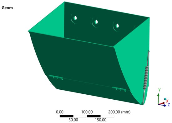
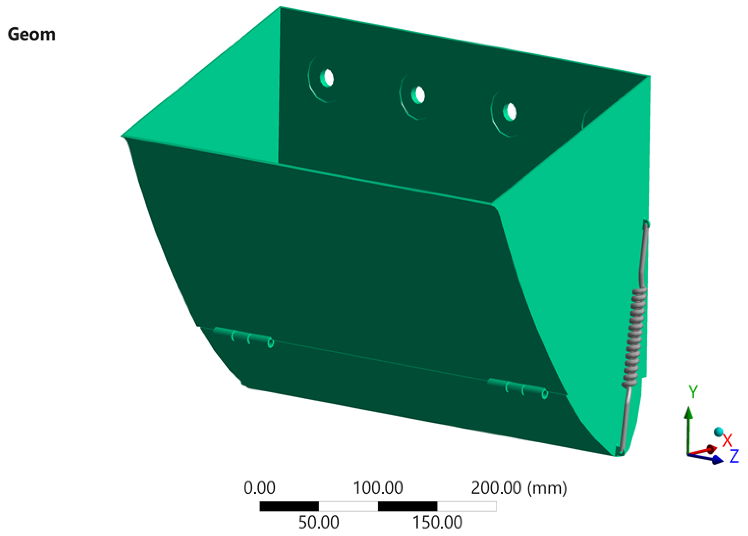
According to the design concept, the movable bottom is intended to rotate under the action of the grain mass during the filling process. Such a mechanism facilitates the unloading of bulk material and increases the effective working volume of the bucket. At the same time, the presence of movable elements and spring connections introduces additional stress concentration zones, particularly near the hinge joints and spring attachment points. Therefore, numerical analysis of the stress–strain state of the structure is necessary to evaluate the reliability of the design [10,11,12,13]. The three-dimensional geometric model of the bucket used for finite element analysis is shown in Figure 1.
Figure 1.
Three-dimensional geometric model of the elevator bucket with a movable bottom and side springs.
The internal surfaces of the bucket are subjected to loads caused by the pressure of the transported bulk material. In this study, two alternative approaches were considered for representing this loading condition.
The first approach assumes a conservative loading scheme in which the entire weight of the grain is applied as a uniformly distributed pressure acting on the bucket bottom. This scenario provides a simplified estimation of the maximum structural load and allows verification of the strength margin under worst-case conditions [13,14,15,16,17].
The second approach represents a more realistic loading condition, where the pressure increases with the depth of the grain layer inside the bucket. In this case, the pressure distribution is applied in a stepwise manner to three horizontal zones of the side walls as well as to the bottom surface. This method more accurately reflects the physical behavior of bulk materials and allows a better assessment of the structural response of the bucket walls and the lower hinge assembly.
2.2. Material Properties
St3 structural steel is adopted as a baseline material for this preliminary assessment of a grain-handling elevator bucket. This choice does not establish St3 as the optimal production material. For unchanged geometry, loading, boundary conditions, and elastic constants, increasing the yield strength alone would increase the yield-based safety factor without changing the linear elastic stress distribution.
The properties listed in Table 1 are adopted model inputs rather than certified properties of a manufactured bucket. In particular, the assumed yield strength of 245 MPa is used to calculate a preliminary yield-based safety factor for the modeled load case. Production material selection requires consideration of the material grade, product thickness, delivery condition, weldability, toughness, and operating conditions.
Table 1.
Assumed mechanical properties of the St3 baseline material used in the simulation.
The adopted elastic modulus, Poisson’s ratio, and density are consistent with the structural-steel reference inputs in the ANSYS Mechanical APDL Verification Manual, example VM281 [19]. The numerical simulations were performed using ANSYS Workbench/Mechanical, Release 2025 R1 (ANSYS, Inc., Canonsburg, PA, USA). These reference inputs are not experimentally measured properties of the manufactured bucket.
In Table 1, E is Young’s modulus, N is Poisson’s ratio, P is steel density, σy is yield strength, σu is ultimate tensile strength, and σeq is equivalent von Mises stress. Density refers to steel in Table 1 and to grain in Section 2.3, as specified locally.
2.3. Determination of Grain Loading
The areas of the three occupied grain zones used in the volume calculation represent an approximately 70% bucket filling level. This filling level is already accounted for in the adopted geometry; therefore, no additional multiplication by a filling factor of 0.7 is applied.
For a bucket length of L = 0.4 m, the grain volumes corresponding to the three zones are calculated as follows:
V1 = 0.005 × 0.4 = 0.002 m3; V2 = 0.009403 × 0.4 = 0.0037612 m3;
V3 = 0.0123 × 0.4 = 0.00492 m3.
V3 = 0.0123 × 0.4 = 0.00492 m3.
The total grain volume is therefore
V = 0.0106812 m3.
Assuming a grain bulk density of ρ = 750 kg/m3, defined as the grain mass per unit bulk volume including interparticle voids and adopted here as a loading assumption, the mass of the transported material is calculated as follows:
and the corresponding weight force is
m = ρ × V = 8.01 kg,
G = mg = 78.6 N.
Here, L is bucket length (m); V1, V2, and V3 are the grain volumes in the three zones (m3); V is their total volume (m3); ρ is grain bulk density (kg/m3); m is total grain mass (kg); G is grain weight (N); and g = 9.81 m/s2 is gravitational acceleration. The symbol p denotes pressure, whereas ρ denotes density.
For engineering analysis, two loading scenarios were considered.
- Case 1—Uniform pressure on the bottom
In the first scenario, the entire grain weight is assumed to act on the bucket bottom as a uniformly distributed pressure. For a bottom area of A = 0.01 m2, the base pressure is
Considering the feeding dynamic coefficient kd = 1.5 and the drum inertia coefficient kin = 4.315, the design pressure used for strength verification becomes
pbottom = 0.05087 MPa
This case represents a conservative loading condition.
- Case 2—Pressure increasing with grain depth
In the second scenario, the pressure is assumed to increase with the depth of the grain layer.
For an effective grain height of
the base pressure at the bottom is calculated as
heff = 0.21 m
pdepth0 = ρgheff = 0.001545 MPa
Taking into account the coefficients kd = 1.5 kin = 4.315, the design bottom pressure becomes
pbottom = 0.0100 MPa
The lateral pressure on the bucket walls is determined using the coefficient
K = 0.4
Thus, the pressures applied to the three horizontal wall zones are as follows:
Upper zone: 0.0008 MPa;
Middle zone: 0.0024 MPa;
Lower zone: 0.0040 MPa.
These values correspond to the upper, middle, and lower wall regions of the bucket, respectively, and are summarized in Table 2.
Table 2.
Design grain pressure inputs used in ANSYS Workbench for Case 1 (uniform bottom pressure based on the total grain weight) and Case 2 (depth-dependent pressure represented by bottom pressure and three lateral wall-pressure zones).
In the loading equations, A is the loaded bottom area (m2); pbottom0 is the unamplified pressure in Case 1; pdepth0 is the unamplified pressure in Case 2; and pbottom is the design bottom pressure for the respective case. The symbol heff denotes effective grain depth (m). The dimensionless coefficients kd and kin are the adopted feeding dynamic and drum inertia multipliers, respectively; K is the lateral-to-vertical pressure ratio. Subscripts identify the loading case or pressure location.
The pressures listed in Table 2 were applied to the corresponding internal surfaces of the bucket in the ANSYS Workbench finite element model.
Modeling of Bulk Material Motion During Bucket Discharge
The purpose of this subsection is to provide theoretical background on material motion during discharge, an operating stage relevant to the intended function of the movable-bottom bucket. The description outlines the conditions of particle sliding and separation and complements the discussion of the bucket operating principle. It should not be interpreted as a particle-motion simulation performed within the present static finite element analysis or as evidence of improved unloading performance. The structural results reported below concern the response to the prescribed grain-pressure loading.
During the discharge process of a bucket elevator, part of the conveyed material separates from the bucket directly within the discharge zone, while the remaining material initially moves along the inner surface of the bucket. As the bucket changes its position, the material particle moves relative to the bucket surface under the combined effects of gravity, inertia, and friction. Subsequently, the particle separates from the bucket surface and enters free flight.
To describe the motion of a material particle during discharge, three characteristic points can be distinguished, corresponding to the successive stages of its motion:
- The onset of relative motion as the bucket and belt move around the drum (the point at which the material begins to detach from the bucket);
- The separation of the material particle from the bucket surface;
- The limiting position beyond which the material particle can no longer remain inside the bucket.
This representation makes it possible to systematically determine the conditions for the onset of particle sliding, the instant at which the particle separates from the bucket surface, and its subsequent free-flight trajectory. These parameters are determined using a system of equations that accounts for the geometric and kinematic characteristics of particle motion.
The motion of the material during discharge can be described by the following equation:
where:
- m—particle mass, kg;
- r—radius of the assumed circular particle path, m;
- f0—coefficient of static friction between the material and the sliding surface.
In this analytical subsection, m denotes the mass of an individual particle (kg), distinct from the total grain mass in Section 2.3; t is time (s); δ is angular position (rad); and g is gravitational acceleration (m/s2). The symbol r denotes the radius entering the assumed circular-motion equations (m). The angles δ1, δ2, and δ3 identify the onset of sliding, separation, and the limiting position, respectively. The friction angle is denoted by φ, with f0 = tan φ; it is distinct from density ρ. The symbol f in the subsequent expanded expressions denotes the same dimensionless friction coefficient f0. The symbols w and ω denote angular speed (rad/s); h is the polar distance g/ω2 (m); and n in the separation condition denotes normal contact force (N). The symbol ω2 denotes angular speed at separation (rad/s), v2 denotes linear speed at separation (m/s), and Δv denotes relative sliding speed (m/s). These analytical quantities are separate from the prescribed-pressure finite element loading.
Equation (7) can be rearranged by dividing both sides by (mr):
The angle δ1, at which the particle begins to slide along the bucket wall, is determined from the following condition:
Substituting the initial condition into Equation (12) and rearranging the resulting expression yields
Factoring out the common term and performing the necessary algebraic transformations yields
The polar distance is determined from the following expression (12):
The particle separation angle is calculated using the following equation:
from which
The limiting point beyond which the particle can no longer remain inside the bucket is determined by assuming
The angle δ2, at which the particle separates from the bucket, is determined from the following condition:
Solving this expression simultaneously with Equation (8) yields
For convenience, Equation (18) can be rearranged as follows:
The angle δ1 is determined using the method of successive approximations. Then, by assigning a value to δ3, the resulting equation is evaluated.
The point δ2 lies between δ1 and δ3.
where
Once δ2 has been determined, the angular velocity of the particle at the instant of separation is calculated as follows:
Linear velocity at the instant of separation:
Then, the relative sliding velocity is
After separating from the inner surface of the bucket, the particle enters a free-flight regime. At this stage, its subsequent trajectory is governed by its initial coordinates, separation velocity, direction of motion, and gravitational force. Therefore, analysis of the particle’s free motion makes it possible to determine its flight trajectory and the location of the impact point relative to the bucket and the material receiving zone.
2.4. Finite Element Mesh
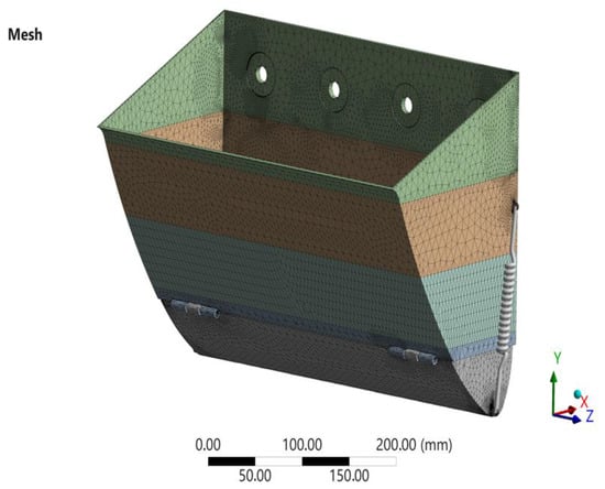
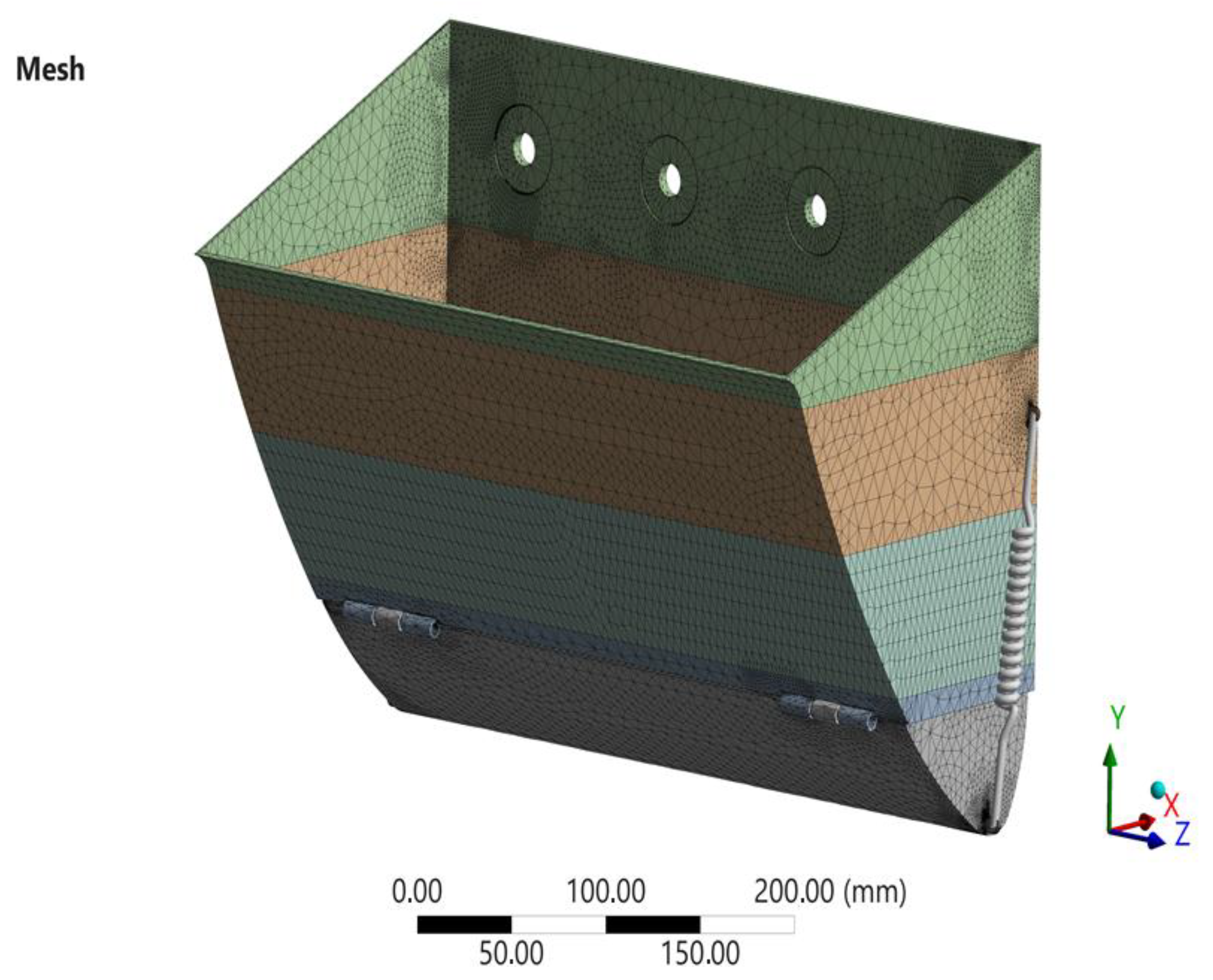
The numerical discretization of the model was performed using tetrahedral finite elements, with local mesh refinement applied in regions where stress concentrations were expected. These regions include the lower hinge connection, the corner joints between the movable bottom and the side walls, the spring attachment area, and the mounting holes located on the rear wall of the bucket. Such a meshing strategy provides an optimal compromise between computational efficiency and solution accuracy.
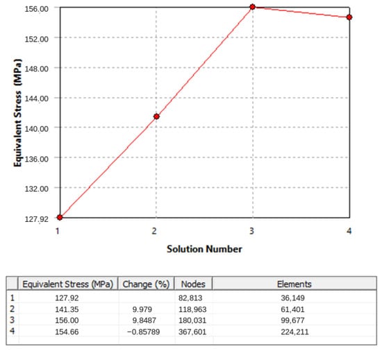
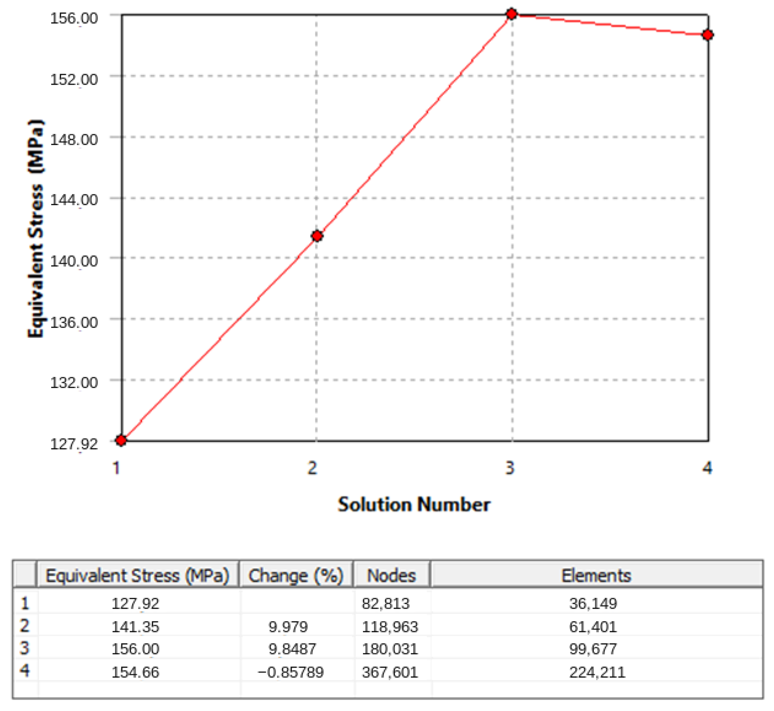
The final finite element model contains 367,601 nodes and 224,211 elements. The maximum equivalent stresses obtained with the penultimate and final mesh configurations are 156.00 and 154.66 MPa, respectively, corresponding to an absolute relative difference of approximately 0.86%. This comparison indicates reduced sensitivity to the final mesh refinement step but does not quantify the overall accuracy of the model [20,21,22,23,24,25,26,27].
The geometric model and the corresponding finite element mesh used in the analysis are presented in Figure 2.
Figure 2.
Tetrahedral finite element mesh of the bucket assembly with refinement in connection regions.
2.5. Contacts, Springs, and Boundary Conditions
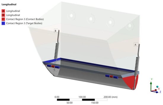
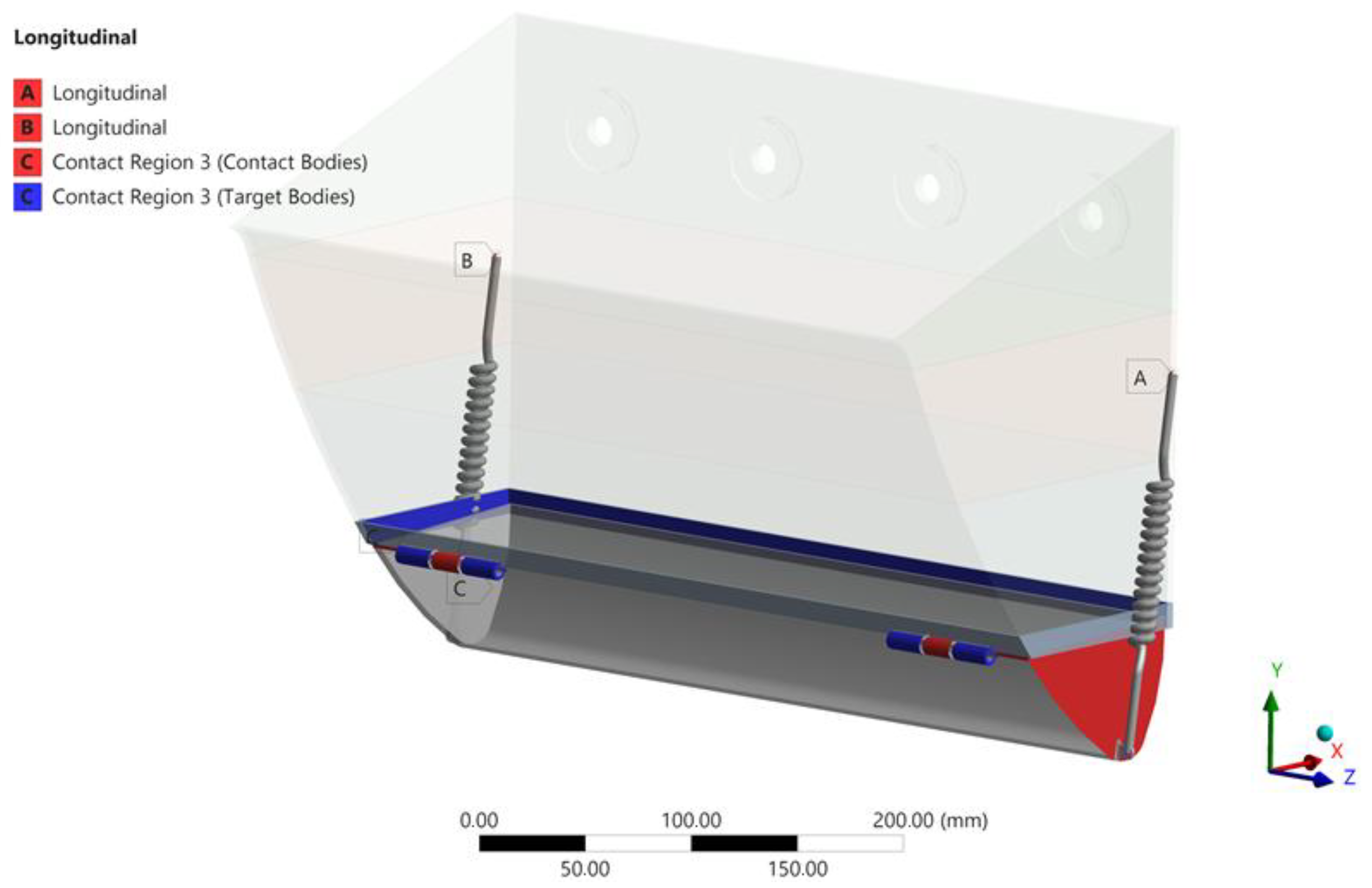
The model accounts for contact interactions between the movable bottom and the corresponding structural elements of the bucket. Within the framework of a static engineering formulation, these contacts are interpreted as working connections without significant sliding. The analysis therefore focuses primarily on the transmission of forces and the formation of local stress peaks in the support and rotation zones (Figure 3).
Figure 3.
Modeling of contacts and springs.
The side springs are modeled as linear longitudinal elastic elements (Longitudinal Spring) that resist tensile forces and limit the displacement of the lower right node of the bucket structure (Figure 3). In the updated formulation, the spring pretension is additionally considered, which is particularly important for the configuration with a closed movable bottom.
According to the ANSYS Mechanical User Guide, the preload of a linear spring can be specified either by defining the free length parameter (Free Length) or by applying an equivalent initial force (Load).
For the refined computational model, the following parameters were adopted:
- -
- Spring stiffness: k = 1.08 N/mm;
- -
- Actual spring length: Lspring = 180.11 mm;
- -
- Initial pretension force: F0 = 70 N.
The corresponding analytical relations and the equivalent free spring length used for defining the preload are presented below.
Here, ΔL is spring extension (mm), F0 is initial spring tensile force (N), k is spring stiffness (N/mm), Lspring is installed spring length (mm), and Lfree is free spring length (mm). The designation Lspring in the input list denotes the same installed length.
Thus, in order to define the spring pretension through the free length parameter in ANSYS Mechanical, the value of 115.30 mm should be used. When the preload is specified through the alternative method using force, the value Preload = 70 N can be directly applied.
If, under the same geometric conditions, the parameter Free Length = 65 mm is used instead, the initial spring force increases to 124.32 N, which results in an overestimated spring reaction and a significantly stiffer resistance to the opening of the movable bottom. Therefore, accurate definition of the spring pretension is essential for realistic simulation of the bucket opening mechanism and for correct prediction of the stress distribution in the lower structural assembly Figure 3.
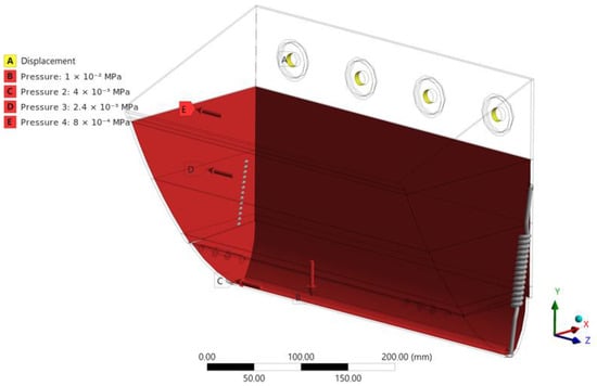
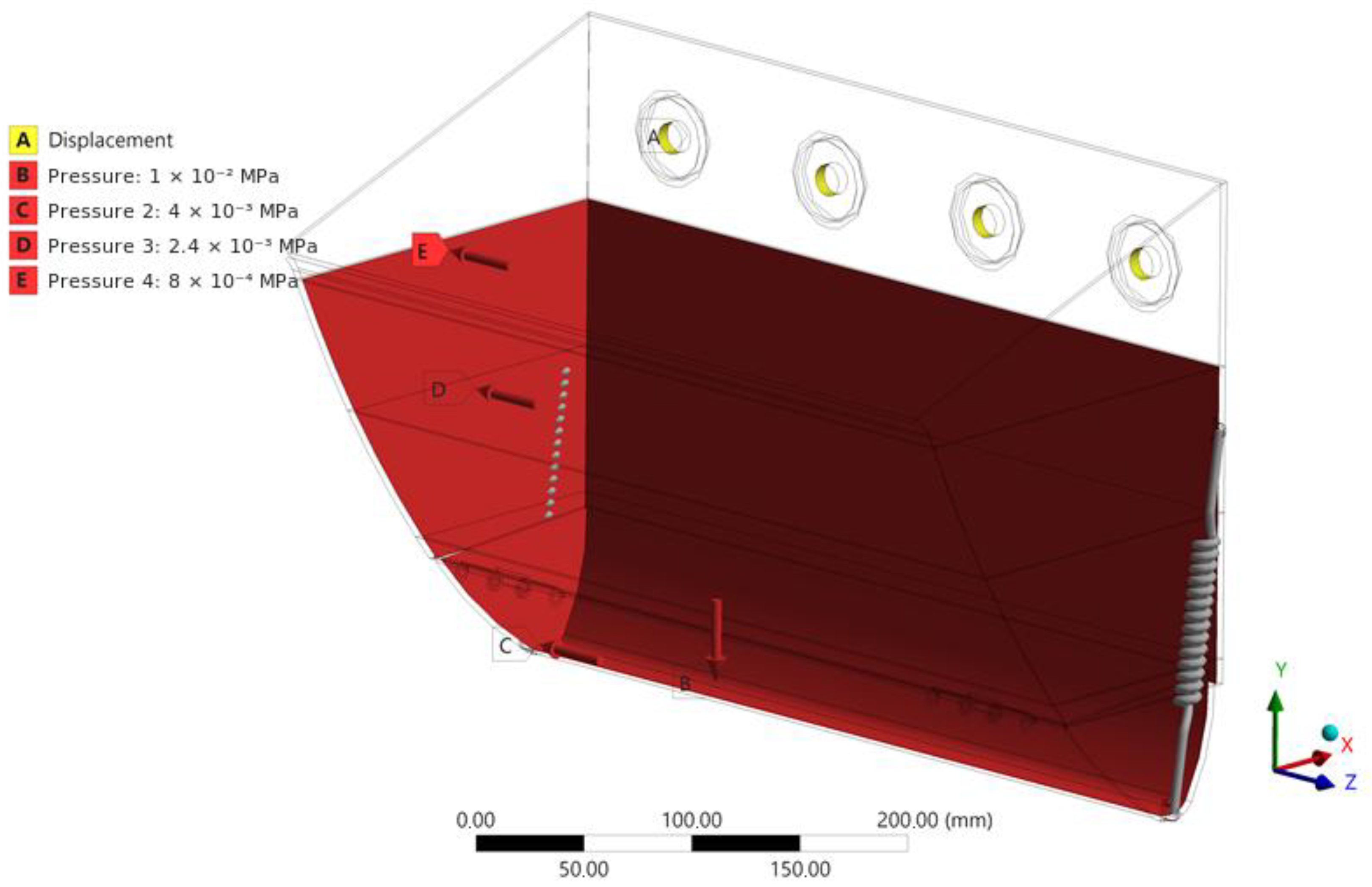
The mounting boundary condition is applied to the inner cylindrical surfaces of the four fastening holes in the rear wall, identified as region A in Figure 4. A displacement boundary condition is used in ANSYS Mechanical to represent the attachment of the bucket to the elevator traction element. The restraint is applied locally at the mounting holes, rather than over the entire rear wall. The bucket walls and movable-bottom assembly deform relative to this restrained region, with forces transmitted through the bottom-to-body connections and longitudinal springs described above. The flexibility of the traction element and the compliance of the fastening assembly are not explicitly modeled; therefore, the calculated stresses and displacements should be interpreted within the adopted mounting idealization.
Figure 4.
Mounting restraint and applied pressures for the depth-dependent loading case. A: Displacement boundary condition at the four rear-wall fastening holes; B: bottom pressure, 0.0100 MPa; C–E: lower, middle, and upper wall-zone pressures of 0.0040, 0.0024, and 0.0008 MPa, respectively.
The displayed time of 1 s denotes the endpoint of a static load step in ANSYS, rather than a simulated operational duration. The analysis evaluates static equilibrium under the prescribed loads and spring pretension; it does not resolve the time-dependent response of the bucket [19,20].
2.6. Modeling Assumptions and Limitations
The model provides a preliminary assessment of the bucket under prescribed static loading conditions. A linear elastic material formulation is used with the properties listed in Table 1. Grain loading is represented by distributed pressures for the two scenarios described in Section 2.3, assuming a bulk density of 750 kg/m3 and approximately 70% filling. The amplification coefficients account for increased pressure magnitudes within this static formulation.
The contacts and mounting constraints are idealized as described in Section 2.5. The side springs are represented as linear longitudinal elements using the adopted stiffness and pretension specified in that section. These idealizations define the scope of the predicted stresses and displacements. The calculated safety factor relates to yielding under the modeled conditions; fatigue, impact response, and welded-joint strength require separate assessments. The mesh refinement comparison evaluates sensitivity to discretization. Further sensitivity analysis and experimental validation would support assessment of the model’s applicability to actual operating conditions.
A separate assessment of welded-joint strength was not performed. Therefore, the reported maximum von Mises stress should not be interpreted as verification of weld strength. The influence of weld geometry and properties on local stresses requires further investigation.
3. Results
3.1. Equivalent Stress Distribution
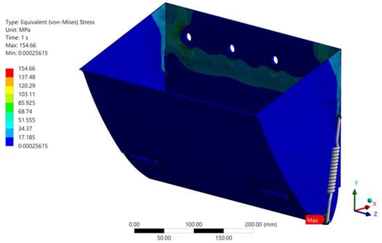
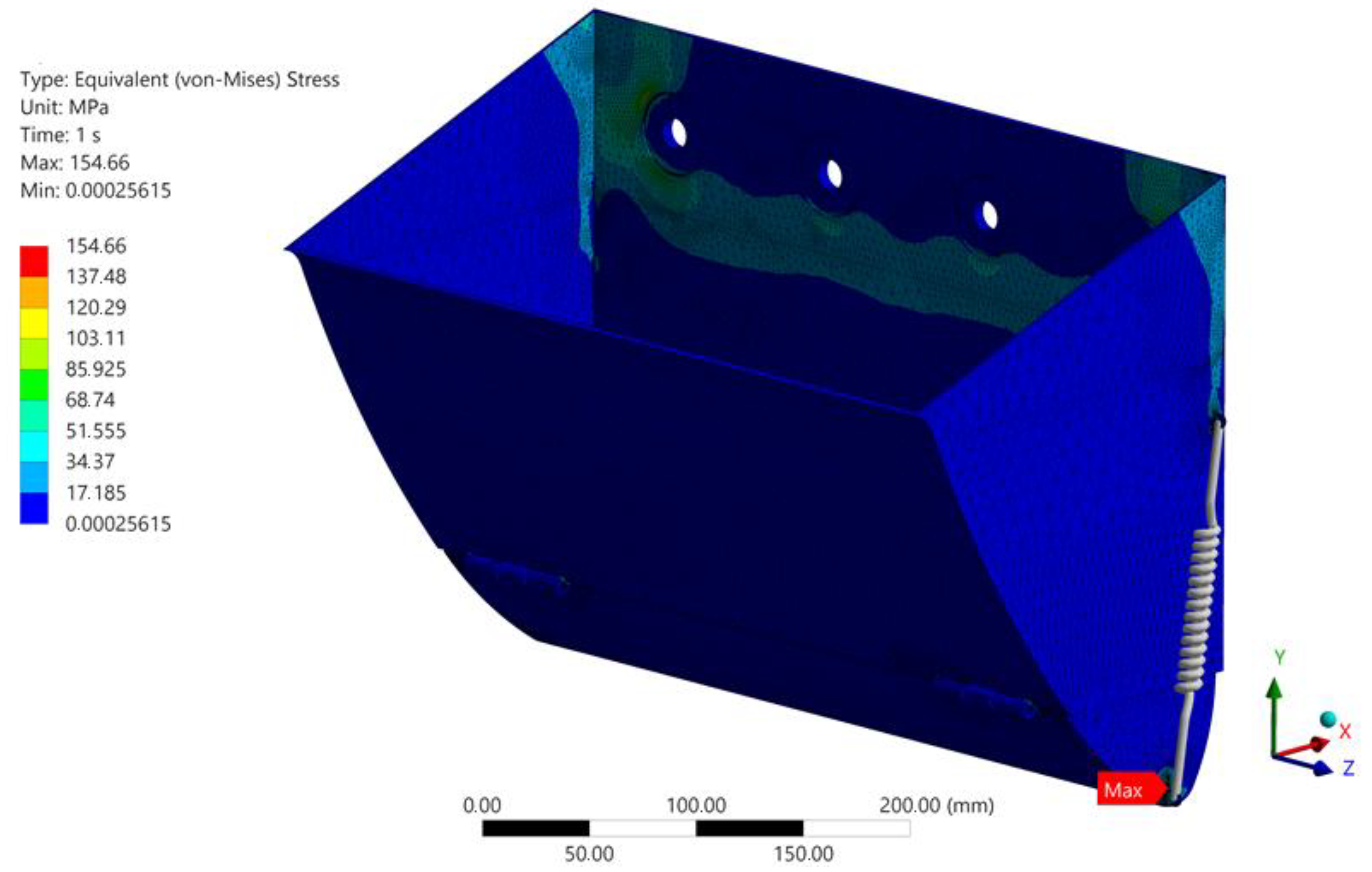
According to the results of the static structural analysis, the maximum equivalent von Mises stress reaches 154.66 MPa, while the minimum stress values are close to zero and correspond to unloaded regions of the structure.
The critical stress zone is localized in the lower right node of the bucket, specifically in the region where the side wall, the movable bottom element, and the spring attachment joint intersect.
This stress distribution has a clear engineering explanation. First, this region represents the transition zone where the load transfer path from the grain pressure is redirected toward the support and rotation area of the movable bottom. Second, the node combines several factors that contribute to stress concentration, including geometric discontinuities, local flexibility introduced by the spring connection, and variations in shell stiffness. Third, due to the stepwise pressure distribution applied to the wall zones, the highest lateral load component acts on the lower portion of the side wall. Therefore, the lower right structural node should be considered the primary candidate for structural reinforcement (Figure 5).
Figure 5.
Distribution of equivalent (von Mises) stresses in the bucket structure.
Assuming the yield strength of St3 structural steel to be 245 MPa, the estimated safety factor with respect to yielding can be calculated as
n = 1.58
Here, n is the dimensionless yield-based safety factor, defined as σeq,max; σy = 245 MPa is the adopted yield strength and σeq,max = 154.66 MPa is the reported maximum equivalent von Mises stress. This safety-factor symbol is distinct from the normal-force symbol used in the section modeling of bulk material motion during bucket discharge.
The nominal yield-based safety factor is approximately 1.58 (Table 3). This value applies only to the assumed material properties and the modeled static loading and boundary conditions. It does not, by itself, demonstrate operational safety or compliance with a design standard.
Table 3.
Summary of the stress analysis results.
3.2. Deformations and Displacements
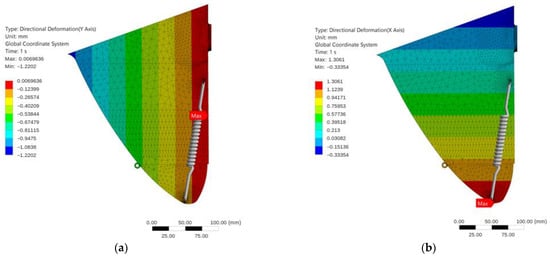
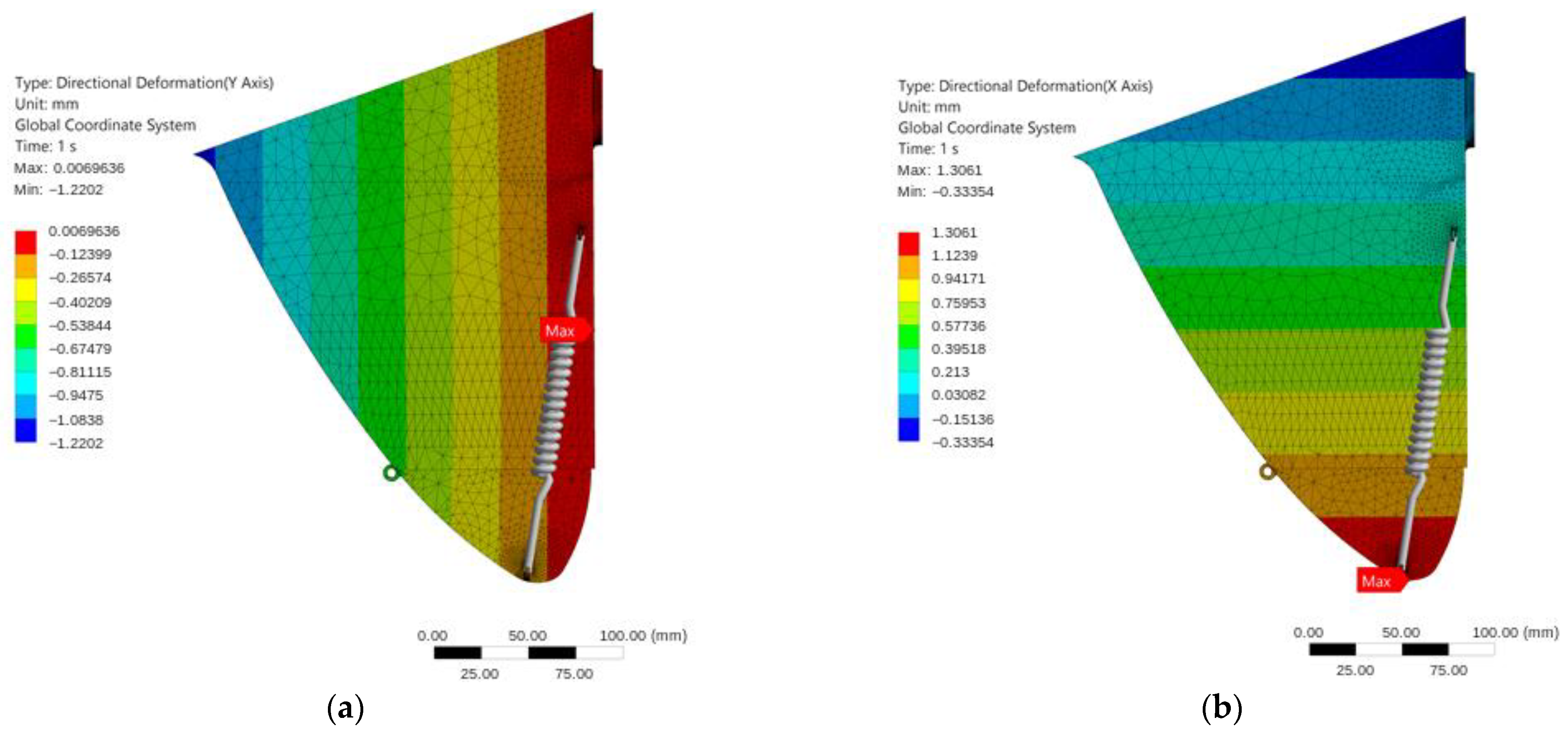
The minimum and maximum directional displacements are summarized in Table 4. The reported directional displacements range from −1.2202 to 0.0097 mm along the Y-axis and from −0.3335 to 1.3061 mm along the X-axis (Figure 6). These values describe the calculated static response under the prescribed loading and support conditions; their agreement with the response of a physical bucket remains to be assessed.
Table 4.
Summary of directional deformation results.
Figure 6.
Directional deformation fields along (a) the Y- and (b) X-axes.
The largest calculated displacements occur in the lower part of the movable bottom and near the lower hinge joint. The comparatively small displacement of the upper mounting region is consistent with the imposed support idealization but does not independently validate the boundary conditions.
The displacement pattern is compatible with the assumed movable-bottom configuration and provides a prediction for comparison with future physical measurements.
3.3. Mesh Convergence Analysis
To verify the reliability of the numerical solution, a mesh convergence study was performed by sequentially refining the finite element mesh using four discretization variants. The maximum equivalent von Mises stress was selected as the control parameter because it directly determines the structural safety margin and is the most sensitive indicator to local mesh refinement in regions of stress concentration.
The reported maximum von Mises stress stabilizes with progressive mesh refinement. This comparison assesses numerical sensitivity to discretization within the adopted model and does not constitute experimental validation.
Figure 7 illustrates the variation in peak equivalent stress with mesh refinement. As shown in Table 5, the peak equivalent stress changes substantially during the initial refinement stages and then stabilizes. The difference between the third and fourth mesh variants is less than 1%, indicating limited sensitivity of this response quantity to the final refinement step.
Figure 7.
Mesh convergence analysis.
Table 5.
Mesh convergence analysis data.
This mesh comparison concerns the reported peak stress within the adopted formulation; it does not establish the accuracy of the loading, contact, or support assumptions.
4. Discussion
The structural assessment addresses how prescribed grain loading is transferred through the bucket body, hinged movable bottom, and pretensioned side springs. The stress field identifies the junction of the movable bottom, side wall, and spring attachment as the principal region requiring further assessment. This localization is consistent with a change in the load path near the movable-bottom connection, where geometric discontinuities and the spring reaction may produce local bending and stress concentration. The present equivalent-stress results support identification of this region, but do not separate the individual contributions of geometry, contact, and spring loading. Establishing their relative importance would require controlled variations of these model inputs.
The stress and displacement fields provide complementary information. The reported maximum equivalent stress remains below the adopted yield strength, giving a yield-based safety factor of approximately 1.58 for the modeled loading condition. This indicates a margin relative to the assumed onset of yielding, rather than compliance with a service-life or fatigue criterion. The concentration of directional displacements near the movable bottom is compatible with the flexibility introduced by this configuration. However, a static displacement field does not establish the opening sequence, discharge performance, or reliability of the mechanism. Likewise, small displacements near restrained regions reflect the support idealization and do not independently validate the boundary conditions.
The mesh study helps distinguish discretization sensitivity from uncertainty in the physical model. The peak equivalent stress changes by less than 1% between the last two meshes, supporting use of the reported value for comparison within the adopted formulation. This observation does not demonstrate convergence of every response quantity or exclude sensitivity to the contact idealization, support conditions, or geometry near the local peak. The two pressure representations also describe alternative loading assumptions; their formulation alone does not establish a quantified difference in structural response. Such a comparison requires results obtained under each loading representation with otherwise identical model settings.
In relation to the literature reviewed in the Introduction, the present analysis provides a local structural perspective on a particular bucket configuration. Material-flow, grain-damage, diagnostic, and system-dynamics studies inform the broader operating context, whereas the calculated fields here identify where the prescribed loads are concentrated within the movable-bottom and side-spring assembly. The contribution is therefore a configuration-specific basis for prioritizing structural assessment. It does not demonstrate an improvement over a conventional bucket, since no matched comparison of alternative bucket designs is reported.
The identified junction provides a reason to evaluate local reinforcement before increasing the thickness of the entire bucket. Candidate modifications include a larger transition radius, local reinforcement around the spring attachment, a stiffening rib, or a change in the spring force application point. These are design hypotheses suggested by the load-transfer interpretation; reductions in stress or mass have not been quantified. Each modification should be assessed under consistent loads and supports, including its influence on hinge motion and the spring reaction. A parametric study of spring stiffness and pretension would also help determine whether the identified stress pattern persists over a practical range of assembly conditions.
The scope remains a preliminary static, linear elastic assessment with prescribed grain pressures and adopted spring properties. Detailed nonlinear contact, plasticity, hinge wear, fatigue, and transient redistribution of grain loading were not resolved. Physical validation was not performed, so the predicted fields should be treated as numerical findings under the stated assumptions. Future validation should compare measured strains and displacements with predictions under controlled loading, using independently characterized material and spring properties and accounting for measurement uncertainty. This would test the predicted location of the critical region and provide a basis for subsequent nonlinear, transient, and fatigue analyses.
5. Conclusions
The objective of assessing the static structural response of the elevator bucket with a movable bottom and pretensioned side springs was addressed by identifying how the prescribed grain loads are distributed through the assembly. Within the adopted model, the junction of the movable bottom, side wall, and spring attachment is the principal region requiring further design attention, making local reinforcement a priority for evaluation. The stress-based yield margin and the concentration of directional displacements near the movable bottom together provide a basis for locating prototype measurements and comparing future design variants. The limited change in peak stress between the final two meshes supports this interpretation within the discretized model, while leaving uncertainty in the loading and connection assumptions unresolved. The study thus provides a configuration-specific basis for prioritizing structural modifications; it does not establish improved conveying performance or operational reliability. Further work should evaluate reinforcement options and sensitivity to spring stiffness, pretension, and connection behavior, followed by physical validation and assessment of transient and cyclic loading.
Author Contributions
K.K.—conceptualization, methodology, validation, formal analysis, investigation, writing—original draft preparation; B.T.—conceptualization, validation, resources, writing—review and editing, supervision, project administration; U.K.—validation; A.T.—software, investigation, data curation, visualization, writing—review and editing; A.K.—methodology. All authors have read and agreed to the published version of the manuscript.
Funding
This research received no external funding.
Institutional Review Board Statement
Not applicable.
Informed Consent Statement
Not applicable.
Data Availability Statement
The data that support the findings of this study are available from the corresponding author upon reasonable request.
Conflicts of Interest
The authors declare no conflicts of interest.
References
- Arunyanart, P.; Kongkaew, N.; Sudsawat, S. Optimizing Bucket Elevator Performance through a Blend of Discrete Element Method, Response Surface Methodology, and Firefly Algorithm Approaches. Comput. Mater. Contin. 2024, 80, 3379–3403. [Google Scholar] [CrossRef] [Scilit]
- Sokolski, P. Suitability of Selected Diagnostic Factors for Assessing the Technical Condition of the Working Systems of Bucket Elevators. Energies 2025, 18, 1610. [Google Scholar] [CrossRef] [Scilit]
- Arunyanart, P.; Kongkaew, N.; Sudsawat, S. Comprehensive DEM Calibration Using Face Central Composite Design and Response Surface Methodology for Rice–PLA Interactions in Enhanced Bucket Elevator Performance. AgriEngineering 2025, 7, 240. [Google Scholar] [CrossRef] [Scilit]
- Nurmagambetov, A.; Kurmanov, A.; Ryspayev, K.; Bekmyrza, Z.; Keklis, A. Analysis of Grain Damage by the Bucket Elevator during Loading/Unloading. Commun. Sci. Lett. Univ. Zilina 2024, 26, B54–B62. [Google Scholar] [CrossRef] [Scilit]
- Jendrysik, S.; Rogala-Rojek, J.; Kowol, D.; Wieczorek, A.N. Operation Optimization of a Bucket Conveyor Transporting Wastes in the Processing Plant of a Hard Coal Mine. Appl. Sci. 2024, 14, 1764. [Google Scholar] [CrossRef] [Scilit]
- Sinnott, M.D.; Hilton, J.E.; McBride, W.; Cleary, P.W. Coupled Gas-Particulate Discharge from a Bucket Elevator. Powder Technol. 2017, 314, 203–217. [Google Scholar] [CrossRef] [Scilit]
- Sokolski, P. Assessment of Suitability for Long-Term Operation of a Bucket Elevator: A Case Study. Energies 2023, 16, 7852. [Google Scholar] [CrossRef] [Scilit]
- He, Z.; Xing, Z.; Zhou, Q.; Chang, L. Dynamic Analysis of a Combined Spiral Bevel Gear and Planetary Gear Set in a Bucket Elevator with High Power Density. Sustainability 2023, 15, 4304. [Google Scholar] [CrossRef] [Scilit]
- Jendrysik, S.; Bartoszek, S.; Bałaga, D.; Kost, G.; Sękala, A. Study of Energy Consumption of a Bucket Conveyor in a Jig Concentrator Plant in a Hard Coal Mine. Energies 2021, 14, 5706. [Google Scholar] [CrossRef] [Scilit]
- Kuanyshbekova, K.; Togizbayeva, B.; Kokayev, U.; Sarsenbayev, M. An Overview of Existing Designs for Belt Bucket Elevators. Eurasian J. Appl. Eng. Technol. 2025, 3, 156–166. [Google Scholar] [CrossRef] [Scilit]
- Chen, Z.; Wassgren, C.; Tamrakar, A.; Ambrose, R.P.K. Validation of a DEM Model for Predicting Grain Damage in an Industrial-Scale Handling System. Smart Agric. Technol. 2023, 5, 100274. [Google Scholar] [CrossRef] [Scilit]
- Horabik, J.; Molenda, M. Parameters and Contact Models for DEM Simulations of Agricultural Granular Materials: A Review. Biosyst. Eng. 2016, 147, 206–225. [Google Scholar] [CrossRef] [Scilit]
- Larsson, S.; Rodríguez Prieto, J.M.; Gustafsson, G.; Häggblad, H.-Å.; Jonsén, P. The Particle Finite Element Method for Transient Granular Material Flow: Modelling and Validation. Comput. Part. Mech. 2021, 8, 135–155. [Google Scholar] [CrossRef] [Scilit]
- Ischuka, O.; Togizbaeva, B. Technique of Drawing Up for the Daily Plan-Schedule of Station Operatin. Transp. Means 2017, 137–140. [Google Scholar]
- Lommen, S.; Mohajeri, J.; Lodewijks, G.; Schott, D. DEM Particle Upscaling for Large-Scale Bulk Handling Equipment and Material Interaction. Powder Technol. 2019, 352, 273–282. [Google Scholar] [CrossRef] [Scilit]
- Togizbayeva, B.; Sazambayeva, B.; Kinzhebayeva, A. Methodology of Justification and Calculation of Rational and Constructive Parameters of a Tube Belt Conveyor. Eurasian J. Appl. Eng. Technol. 2022, 3, 134–140. [Google Scholar] [CrossRef] [Scilit]
- Orefice, L.; Khinast, J.G. DEM Study of Granular Transport in Partially Filled Horizontal Screw Conveyors. Powder Technol. 2017, 305, 347–356. [Google Scholar] [CrossRef] [Scilit]
- Zheng, Q.J.; Xu, M.H.; Chu, K.W.; Pan, R.H.; Yu, A.B. A Coupled FEM/DEM Model for Pipe Conveyor Systems: Analysis of the Contact Forces on Belt. Powder Technol. 2017, 314, 480–489. [Google Scholar] [CrossRef] [Scilit]
- ANSYS, Inc. Mechanical APDL Verification Manual, Release 2025 R1; Example VM281; ANSYS, Inc.: Canonsburg, PA, USA, 2025.
- Thornton, C. Granular Dynamics, Contact Mechanics and Particle System Simulations: A DEM Study; Springer: Cham, Switzerland, 2015. [Google Scholar]
- Zienkiewicz, O.C.; Taylor, R.L.; Zhu, J.Z. The Finite Element Method: Its Basis and Fundamentals, 7th ed.; Elsevier: Oxford, UK, 2013. [Google Scholar]
- Bathe, K.J. Finite Element Procedures; Klaus-Jürgen Bathe: Watertown, MA, USA, 2006. [Google Scholar]
- Cook, R.D.; Malkus, D.S.; Plesha, M.E.; Witt, R.J. Concepts and Applications of Finite Element Analysis; Wiley: Hoboken, NJ, USA, 2001. [Google Scholar]
- Reddy, J.N. An Introduction to the Finite Element Method; McGraw-Hill: New York, NY, USA, 2005. [Google Scholar]
- Pilkey, W.D.; Pilkey, D.F.; Bi, Z. Peterson’s Stress Concentration Factors, 4th ed.; Wiley: Hoboken, NJ, USA, 2020. [Google Scholar]
- Kadyrov, A.; Karsakova, A.; Donenbayev, B.; Balabekova, K. Establishing the Strength Characteristics of the Lifting-Leveling Device Structures of the VPO-3-3000 Machines for the Track Straightening. Commun. Sci. Lett. Univ. Zilina 2020, 22, 70–79. [Google Scholar] [CrossRef] [Scilit]
- Kadyrov, A.S.; Pak, I.A.; Ganyukov, A.; Imanov, M.O.; Balabekova, K. Research of Operation of Equipment for Ultrasonic Purification of Exhaust Gases of Internal Combustion Engines. J. Eng. Phys. Thermophys. 2021, 94, 1407–1414. [Google Scholar] [CrossRef] [Scilit]

Disclaimer/Publisher’s Note: The statements, opinions and data contained in all publications are solely those of the individual author(s) and contributor(s) and not of MDPI and/or the editor(s). MDPI and/or the editor(s) disclaim responsibility for any injury to people or property resulting from any ideas, methods, instructions or products referred to in the content. |
© 2026 by the authors. Licensee MDPI, Basel, Switzerland. This article is an open access article distributed under the terms and conditions of the Creative Commons Attribution (CC BY) license.