


Abstract
This article thoroughly documents the focus, long-term monitoring, and survey of the condition of a unique early Gothic wooden ceiling from the 13th century in Zvíkov Castle in the Czech Republic. Through long-term monitoring of climatic parameters, wood moisture, and the movement of ceiling beams, this paper described how wood constantly works, that is, swells and shrinks during a single annual cycle. At the interface of the ceiling beams and the masonry, the ambient temperature ranged from 2.75 °C to 31.75 °C, and the relative humidity of the air from 38 to 93%. The condition of the walled-in beam ends was assessed by resistance drilling and endoscopy. Out of a total of 16 beam ends, 7 ends are completely degraded by brown rot fungus. The condition of the ceiling structure is not good, even in the case of the boards covering the ceiling. Here, the sapwood parts are additionally damaged by the beetle Anobium punctatum which, in combination with rot, has broken down the wood into crumbling matter. High static load due to a massive embankment 35–50 cm thick, two layers of fired paving, and occasional loading causes the wood to deteriorate over time and requires urgent stabilization. The final section reflects on the approach to sustainably securing the uniquely preserved structure. Finding the optimal solution represents a challenging decision-making task between a conservation intervention of external support with minimal intervention in the existing structure and the structural restoration of individual elements, requiring disassembly and reassembly of the structure.
1. Introduction
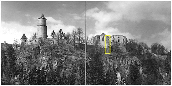
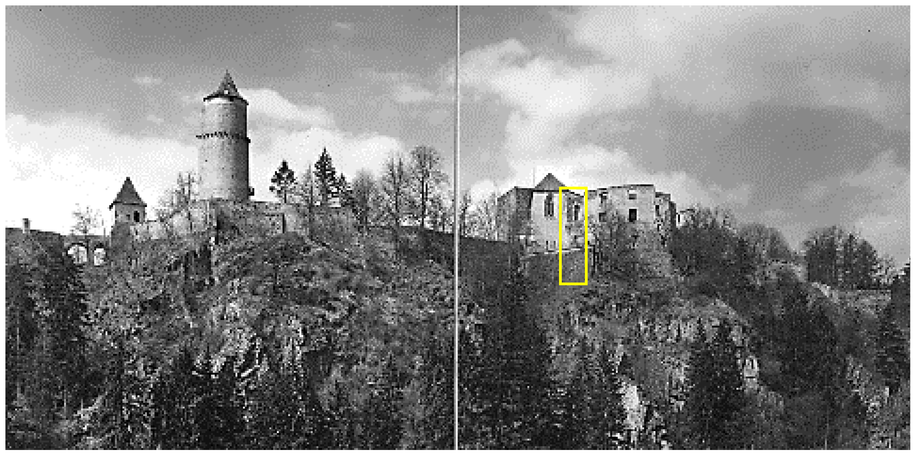
A unique wooden ceiling structure has been preserved at the significant royal castle of Zvíkov in South Bohemia. It supports the floor of the sacristy of the castle chapel of St. Wenceslaus on the first floor of the southern part of the eastern wing of the palace, built during the reign of King Přemysl Otakar II [1]. The sacristy is inserted between the castle chapel itself and a large, vaulted hall, of which only the floor remains, today forming an open terrace; see Figure 1. The sacristy represents a unique and lofty architectural space of a medieval castle. It has a rectangular, slightly skewed layout oriented, with its longer axis in the east–west direction.
Figure 1.
The location of the sacristy and the space beneath it in the castle grounds, which is a partial ruin. (Source NPÚ archive).
The space is vaulted with two bays of a ribbed cross-vault, with ribs of an oval profile, identical to the ribbing in the main chapel. At the points where the ribs intersect at the apex of the vault, a small circular boss is suspended. The vault rests on six corbels, three of which have a pyramidal shape, and the remaining three take the form of a beardless male face. Above all the corbels is a massive cover plate (abacus), onto which the springing of the vault ribs rests. The sacristy is illuminated from the east side by a single two-light pointed window. At its apex, there is tracery in the shape of a droplet, which is the same pattern used in the windows of the chapel vestibule. Below the window is an altar made of large hewn granite blocks. The altar mensa slightly overhangs the base (stipes), and on its front side, a recess for relics (sepulchrum) is carved. The presence of the altar indicates that the sacristy served not only for storing vestments and equipment but also as a separate liturgical space or a smaller chapel. The exact time of origin falls at the end of the 1250s or the beginning of the 1260s, when the royal construction workshop operated at the castle. In written sources, the sacristy (within the chapel) is indirectly documented as of the year 1428. An inventory from 1683 mentions the existence of a pulpit, whose remnants were stored precisely in the sacristy. In 1770, the chapel and sacristy underwent repairs, during which its windows were repaired (a total of five windows in the entire complex of the chapel and sacristy were repaired at that time). During the overall renovation of the castle initiated in 1880, the sacristy was maintained as one of the few preserved parts of the palace. Photographic documentation and surveys from the 20th century confirmed the polychromy of the Gothic architectural elements.
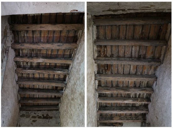
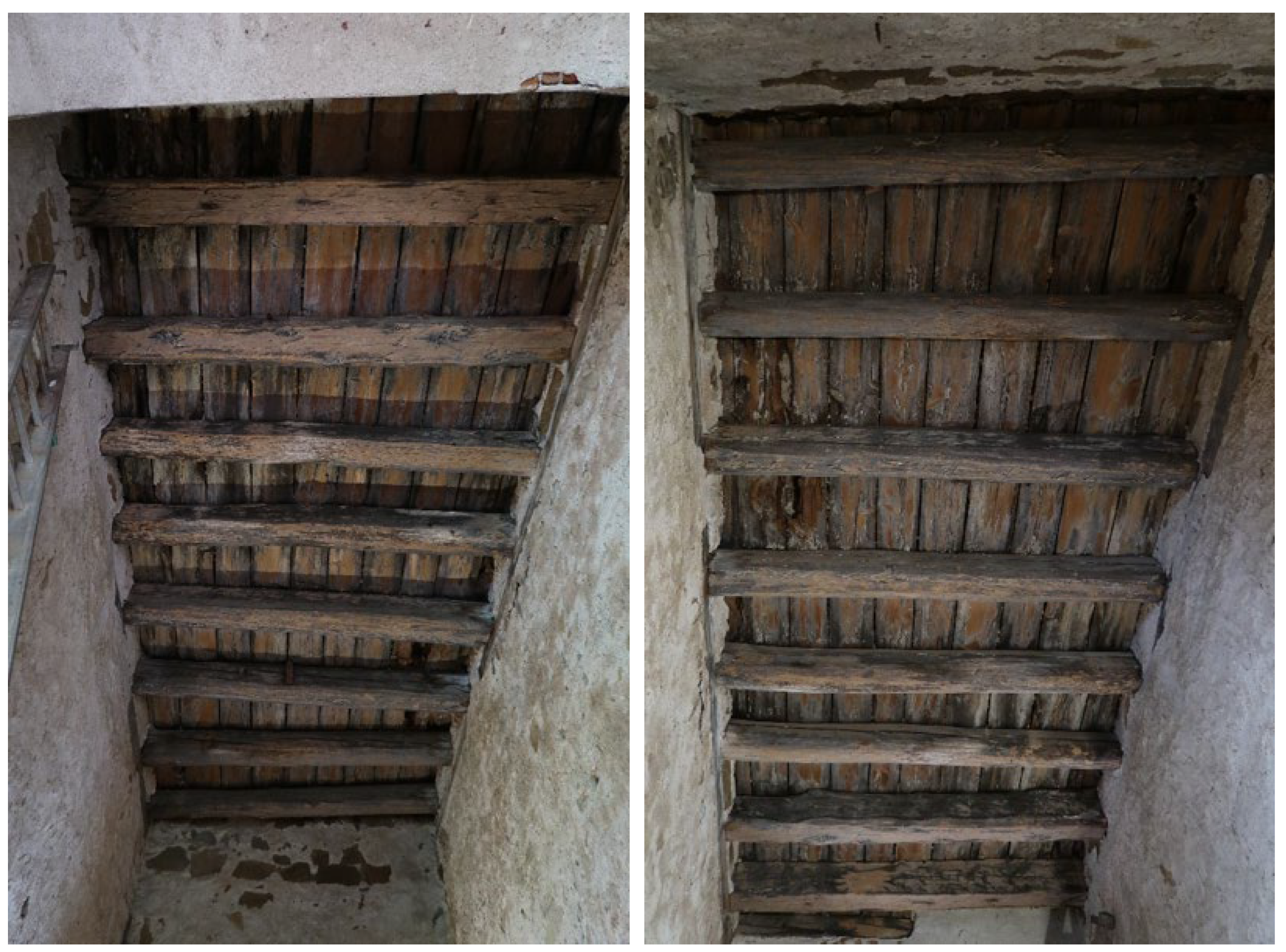
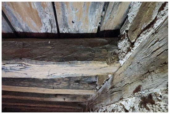
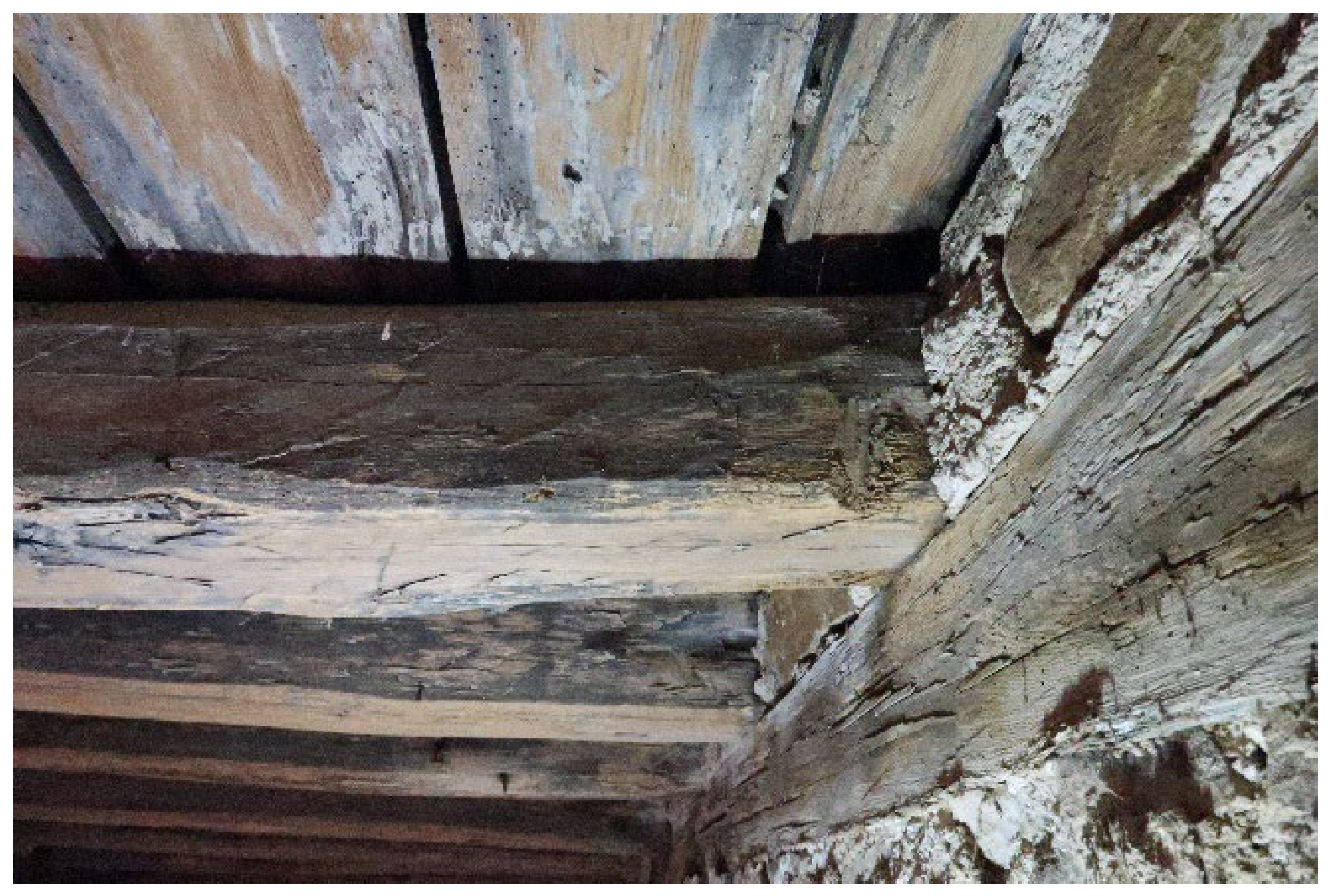
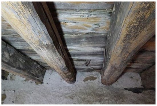
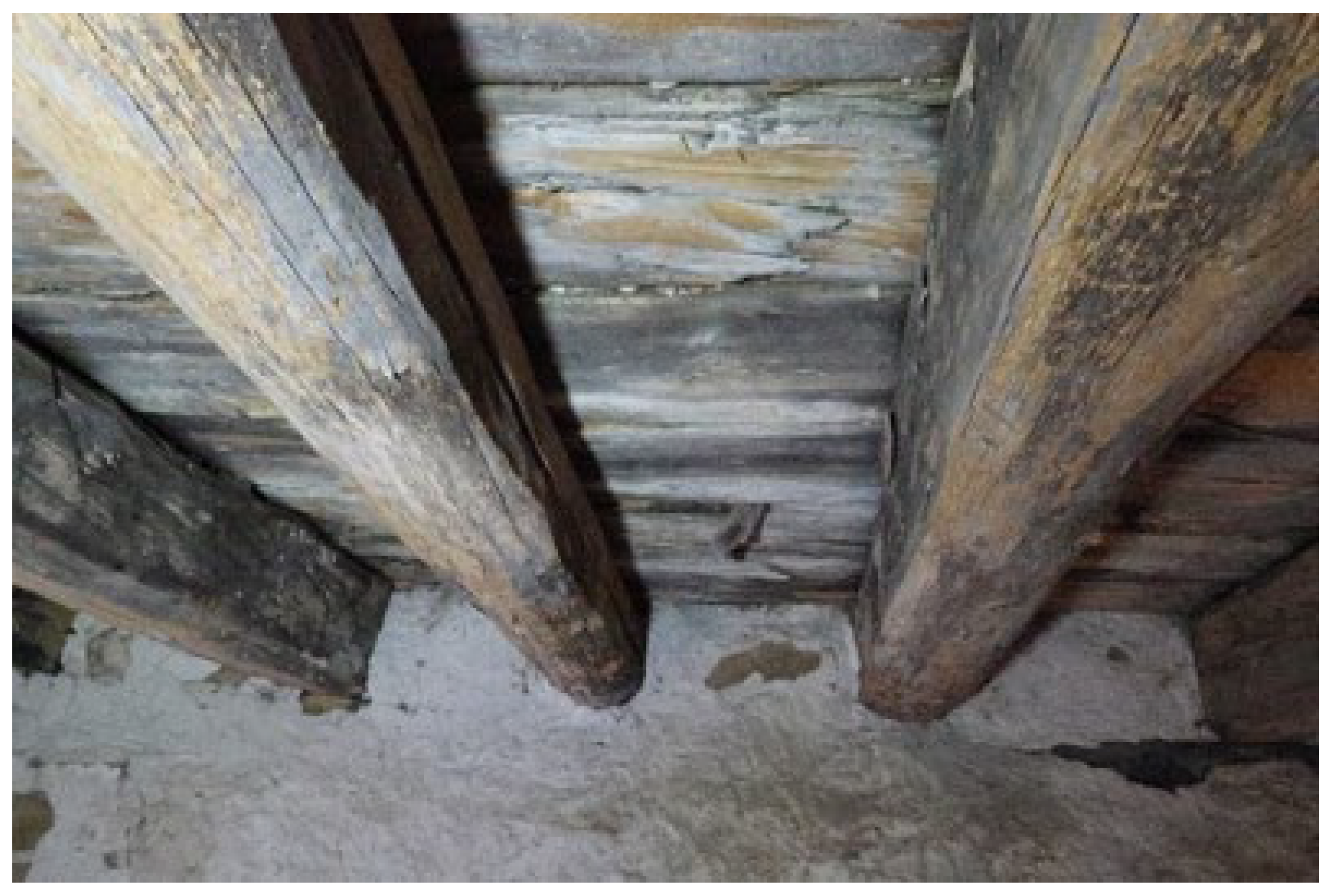
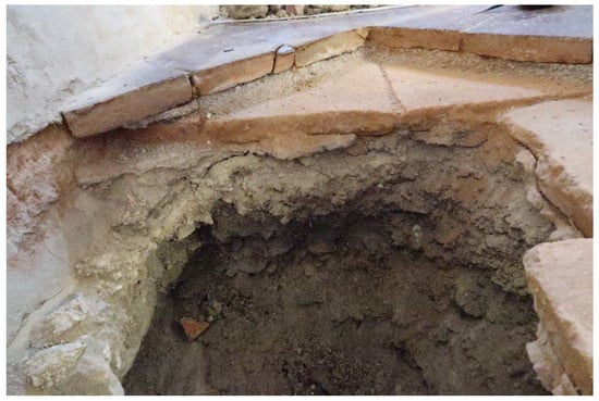
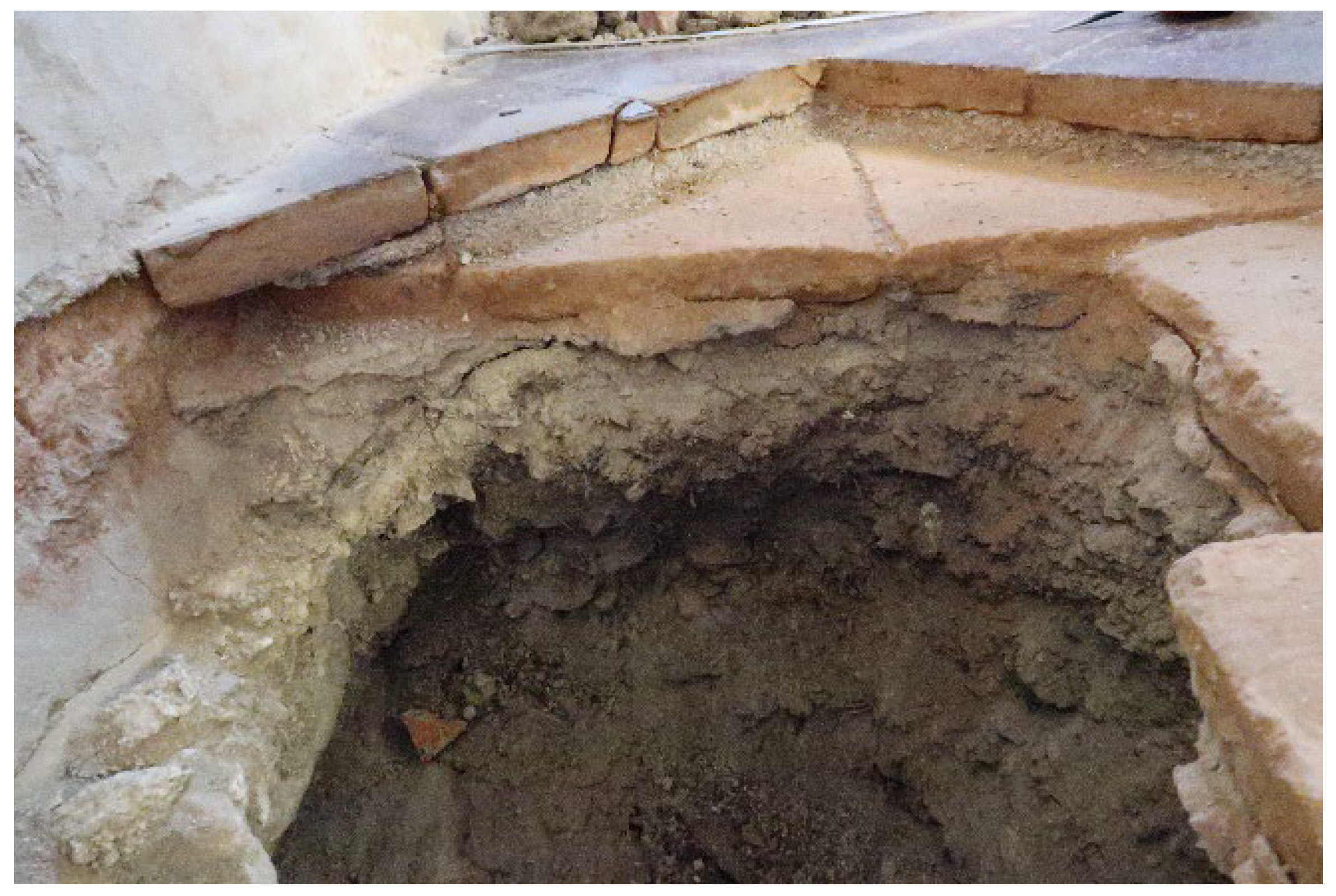
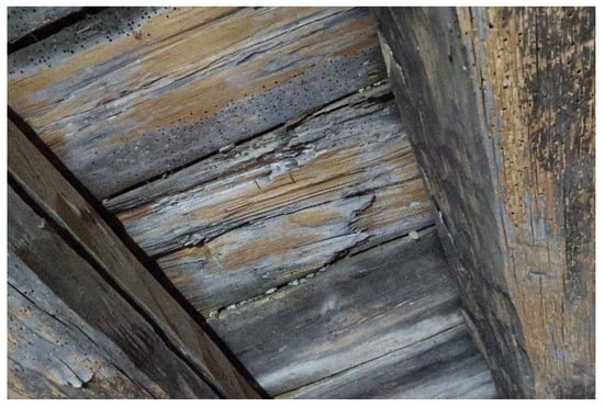
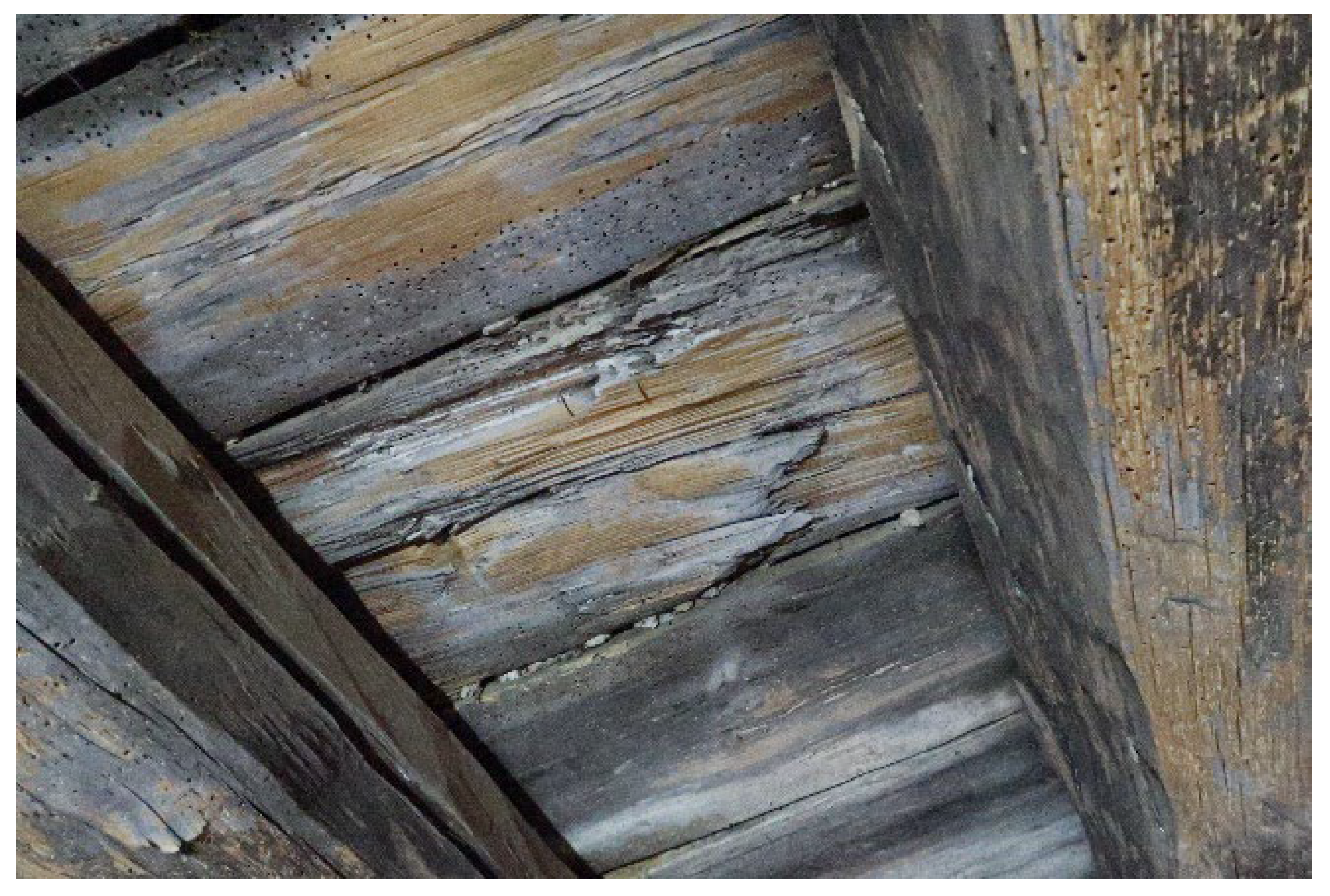
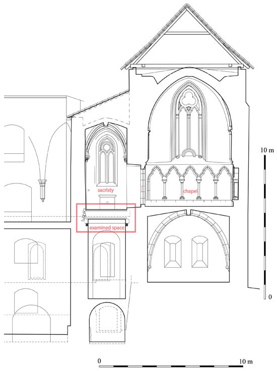
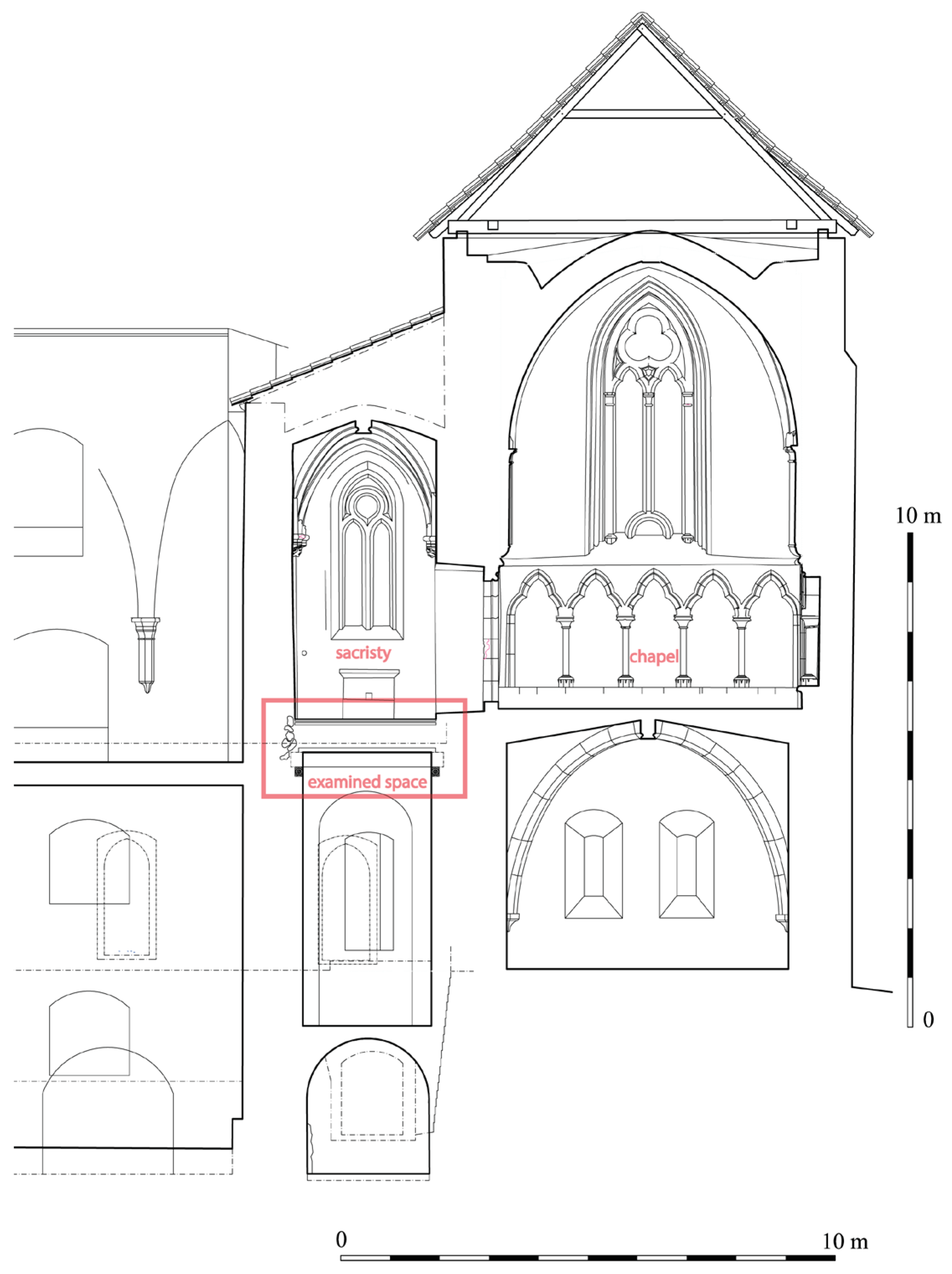
The subject of the research is an exceptionally valuable and uniquely preserved early Gothic ceiling structure under the sacristy of the chapel from the second half of the 13th century. According to available sources, it is the only known example of a comprehensively preserved ceiling structure in Bohemia from this period, which includes not only the supporting elements but also the original layout, boarding, historical coatings, associated plasters, and even the original medieval fill with paving. It is a simple beam ceiling with boarding (Figure 2) [2]. The base is formed by oak sleepers set into the masonry (Figure 3), on which nine oak ceiling beams with a cross-section of approximately 22 × 26 cm are installed. The ceiling beams are roughly hewn and show signs of the original coating. In some parts, they are hewn on all four sides, while in other areas pronounced rounds are preserved (Figure 4), places where the trunk was hewn on only two sides or just from above. The ceiling beams rest on two longitudinal oak sleepers (profile height approx. 23 cm), through which the ceiling load is transferred to the masonry. Above the ceiling beams is a decking of roughly worked split planks (boards, height approx. 10 cm, width 22–34 cm), probably made of fir wood (Figure 5). Above the wooden section, there is a massive, approximately 35–50 cm thick historical fill (containing mortar, small stones, ceramic fragments, debris), on which two layers of fired tiles are laid in a mortar bed (Figure 6). Together with two layers of fired paving, this material creates a significant load on the ceiling structure, corresponding to approximately 7–9 kN per m2. The infill is considered a valuable part of the comprehensively preserved structure, but at the same time, its weight significantly contributes to the current state of emergency and to the crushing of the ends of the load-bearing beams. However, the massive layer of rubble infill protected the medieval wood from the adversities of time for centuries (Figure 7).
Figure 2.
Eastern (left) and western (right) view of the ceiling structure.
Figure 3.
Sleepers embedded in the masonry.
Figure 4.
Ceiling beams worked in various ways.
Figure 5.
Split cladding boards.
Figure 6.
Filling and fired paving with screed.
Figure 7.
Cross-section of the chapel, sacristy, and the examined space.
Due to its integrity and age, this structure is considered the oldest authentically and comprehensively preserved ceiling in the Czech Republic and represents a completelyunique evidence of medieval craft techniques and construction solutions. This ceiling is a perfectly preserved time capsule that contains the entire original medieval system—from the deeply embedded beam capitals to the final layer of fired tiles.
The long-term sustainability of wooden structures is significantly dependent on the environment in which they operate [3,4]. Wood is a hygroscopic building material, meaning it is capable of absorbing and releasing water vapor from the surrounding air. The moisture content of wood (MC) continuously adapts to the immediate climate in its surroundings—wet wood shrinks in a dry environment and dry wood expands in a humid environment. When the moisture content of the wood fully adapts to the surrounding conditions, the wood has reached its equilibrium moisture content (EMC). Equilibrium moisture content is influenced by relative humidity (RH) and temperature (T), with relative humidity having the greatest effect in the temperature range of 0–20 °C. As the climate changes throughout the year, the moisture content in wood also changes. Wood never reaches absolute stability but strives to approach equilibrium moisture content (EMC). For example, at 20 °C and 65% RH, the equilibrium moisture content of wood is approximately 12%. Understanding the quality of the environment in which the wood is stored long term is therefore one of the main factors affecting the design of a conservation intervention.
2. Materials and Methods
In the first step, the measurement of the ceiling structure and adjacent stone walls was carried out. A mobile FARO Orbis 1.0 scanner was used. The measurement record is continuous while moving the scanner without using fixed stations. The point cloud density was thinned to a point spacing of 5 mm. In the space under the sacristy, static flash scans were taken to increase accuracy and reduce noise. After processing the data using FARO Scene, Bentley Microstation, and additional modules, the point clouds were further converted into construction drawings using AutoCAD software. The scanned beam heights were checked using a tape measure for a rough check at the position of their ends.
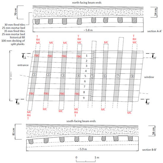
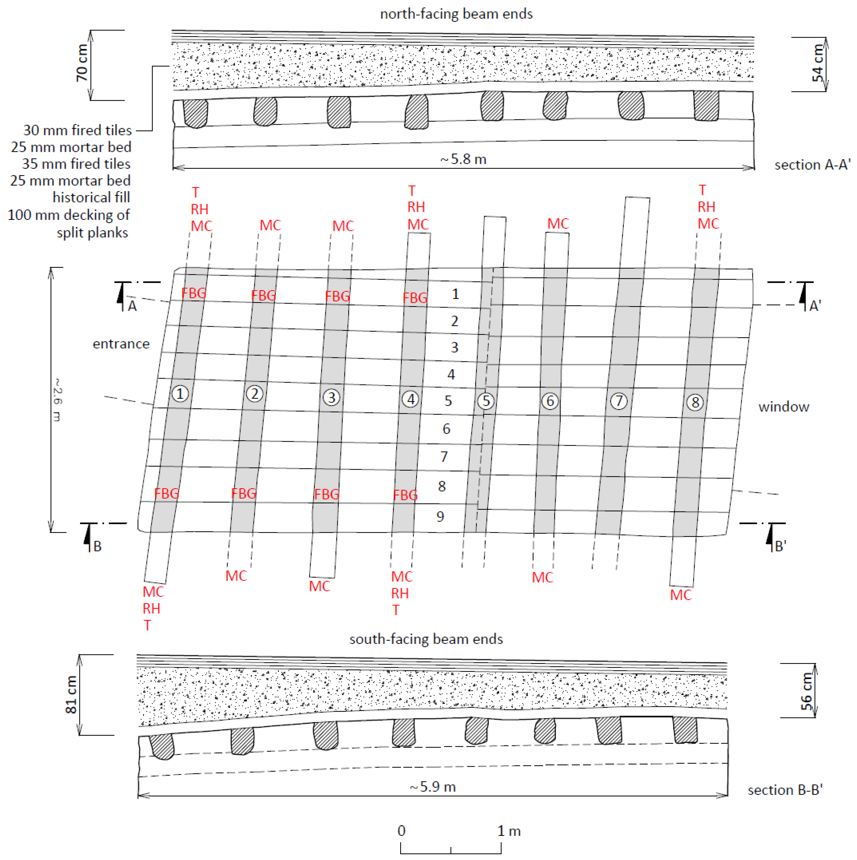
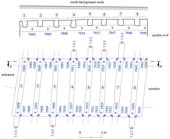
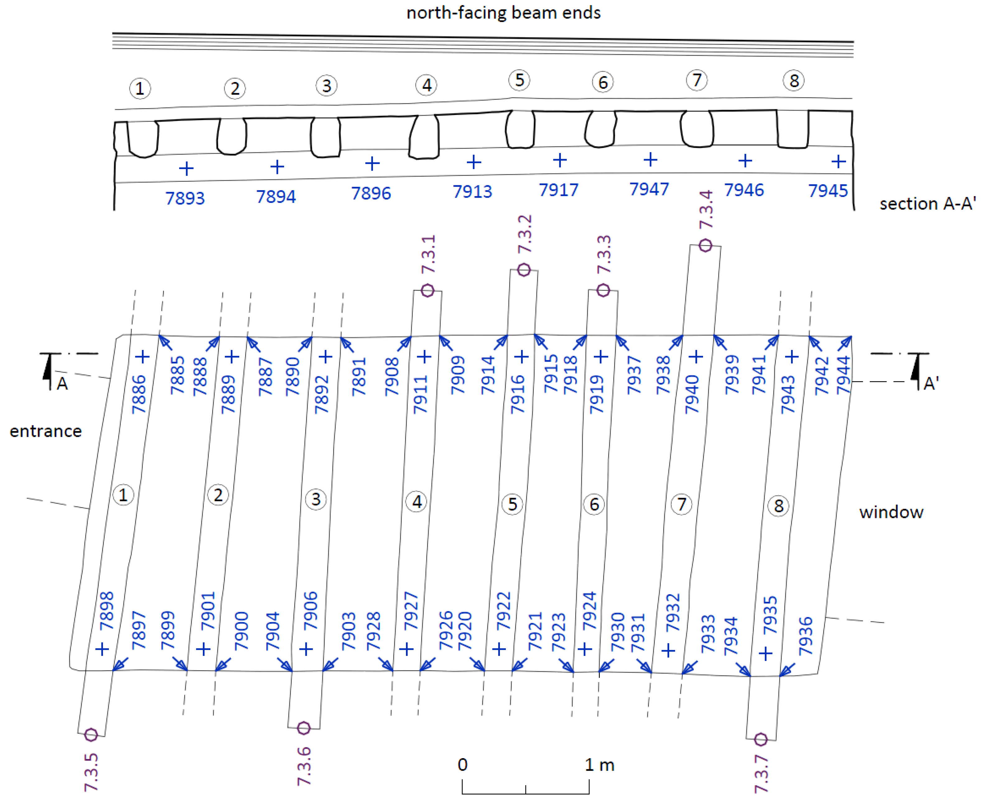
For the purpose of accurately describing the elements and their placement, the ceiling was divided into individual ceiling beams (numbered from west to east) and the corresponding beam ends according to the cardinal directions (north and south). The numbering of the board planks was done according to their arrangement between the ceiling beams and then sequentially from north to south (Figure 8).
Figure 8.
Ceiling plan and sections at the beam ends. Parts marked in red with measurements of T, RH, MC.
Fluctuations in the environmental quality of the ceiling structure’s storage and the resulting structural responses were the subject of long-term monitoring of the ceiling structure under the sacristy. At selected points, relative air humidity (RH), air temperature (T), and wood moisture content (MC) were recorded. All data were stored via the WTZ-24 control unit from the company Elbez Praha (CZ). The measuring control unit was mounted in a plastic enclosure with a programmed OPLC display, a converter board for 12 wood moisture measurement probes, 6 air temperature measurement probes, and 6 relative humidity probes, an SD card, and software for evaluating the measured data. All connectors for the measuring sensors and the power supply network cable were installed on the side of the enclosure. Temperature and relative air humidity were measured using combined sensors with analog (voltage) converters—type T0210. The moisture content of the wood was measured using standardized probes designed for measuring wood moisture in lumber drying kilns with a BNC connector—model WS-16. Chromium steel screws 100 mm in length were used as electrodes. The screws were applied in pairs (distance 20 mm) and driven in at an angle of 45° relative to the beam axis so that the measurement took place at the transition of the ceiling beam into its masonry support. Factory calibration was used, with the goal of capturing the trends in the relative distribution of moisture in the individual beams, even at the cost of reduced accuracy in measuring absolute values. Temperature compensation was carried out based on the air temperature. In the drawing documentation (Figure 8), the heads of the ceiling beams where climatic data and wood moisture were measured are marked with the abbreviations (T), (RH), (MC).
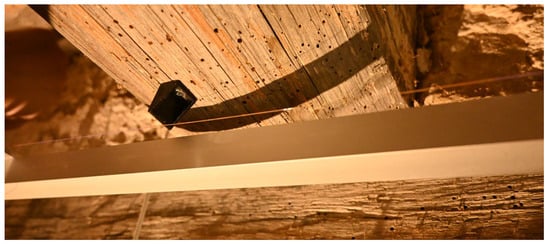
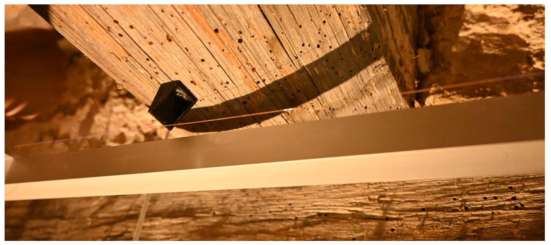
In addition to conventional sensors, which were used to record climatic data (T, RH) and wood moisture (MC), optical fibers for monitoring the deformation of damaged ceiling beams were installed under the selected beam ends [5]. This is a non-invasive method for detecting the movement of the contact surface of ceiling beams using point optical fiber grating sensors (Fiber Bragg Gratings—FBG) with a unit for measuring slow processes (measurement occurs every 3.5 s) from Network Group [6]. The measurement principle is based on measuring the fiber’s length change due to the movement of the beam ends relative to the embedded sleeper. The movement of the beam ends is transferred to the fiber, stretched over a distribution pad (aluminum profile) anchored to the embedded sleeper, through a spacer bushing, which is anchored to the lower surface of the ceiling beam at a distance of about 10 cm from the wall face (Figure 9). Deformation measurements were installed on eight selected beam ends, with visually apparent deformation in the embedded part of the ceiling beam. In the drawing documentation, the heads of the ceiling beams are marked with the abbreviation (FBG). One of the eight installed sensors was used exclusively to measure temperature so that it would be possible to derive the thermal expansion of the materials themselves (quartz fiber and aluminum structure) from the results and thus obtain pure data on the movement of the wood.
Figure 9.
Beam movement measurement using the deflection of an optical fiber.
One FBG channel was used as a temperature reference sensor. The temperature was determined from the Bragg wavelength shift using a calibration coefficient of 9.2 pm/°C.
The temperature-induced wavelength shift was subsequently subtracted from the individual measurement FBG channels.
The strain was calculated from the temperature-compensated wavelength using the effective photoelastic coefficient pe = 0.22.
The calculation further included a correction for the different thermal expansion of the supporting material and the optical fiber. In the applied processing, the thermal expansion coefficients of aluminum and glass were used, and the resulting temperature-induced contribution was subtracted from the calculated strain.
The sensitivity of the FBG sensors to mechanical strain was considered according to the relation vztahu . For a Bragg wavelength of approximately 1550 nm, this corresponds to a wavelength shift of about 1.2 pm/µε. The sensing system was designed to achieve a displacement resolution of at least 1 mm. Calibration measurements confirmed that displacement changes as small as 0.5 mm could be reliably resolved, exceeding the original design requirement.
The entire attachment of the measuring components was carried out with minimal intervention in the wood. Data were recorded automatically at intervals of once every 3.5 s. To calculate the movement of individual beams using Bragg gratings, it is necessary to compensate for the temperature effect, otherwise the overall measurement with the FBG sensors would be significantly inaccurate and distorted. The length of individual fiber segments under the beams was 55 cm, and the deflections corresponding to the movement of the beams were calculated from their length changes. Due to changes in humidity and temperature, the ceiling beams move in both directions (up and down).
Serious defects were found in the structure during the visual inspection. The damage to the ceiling structure under the sacristy of the Zvíkov Castle chapel is primarily caused by wood-destroying rot, currently in a latent state and without current signs of further threat. In the past, the action of wood-destroying rot mainly led to the decomposition of the wood mass in the embedded ends of the oak ceiling beams where, due to rainwater leakage and insufficient ventilation, ideal conditions for rot degradation were created. Further significant damage caused by brown rot wood-destroying fungus is visible in the boarding planks, especially in the sapwood part. The planks were split, laid with the split central surface on the ceiling beams, and the outer sapwood part of the trunk is in contact with the fill, where biotic degradation due to brown rot occurred. In addition, the sapwood part of the floorboards is symbiotically attacked by another wood-destroying pest, which has been identified as wood-destroying insects of the genus Anobiidae, weakening the elements with their feeding. Due to the destruction of structural elements caused by brown rot and the feeding of wood-destroying insect larvae, primarily the mechanical properties of the wood have changed, and along with the reduction of the functional value of the structure, the aesthetic aspect has also deteriorated, which was also observed by others [4,7]. Normally, wood attacked in this way would have to be structurally replaced due to reduced load-bearing capacity. However, we are dealing with an exceptionally historically valuable structure here, which is appropriate to preserve without significant interventions. For a professional discussion on the possibility of stabilizing the ceiling in its current state, it was necessary to refine the visual assessment with a more objective survey of the beam heads. Therefore, in the next phase, a detailed survey of individual beam heads was carried out using micro-invasive methods.
A detailed inspection of the heads of ceiling beams was carried out using resistance drilling, which is based on measuring the resistance against the penetration of a small-diameter drill through the examined material [8]. The device used, the Resistograph, provides an overview of the internal condition of the element. Due to minimal material disturbance, it is classified among semi-destructive methods for determining the condition of wooden structures, suitable for historically significant and heritage buildings. The resistance drill measures the energy required to maintain a constant drill speed while penetrating the material. The drill resistance is concentrated at the tip, whose width is twice that of the shank, which minimizes friction of the drill against the walls of the drilled hole. Lower drilling resistance, which is associated with lower density as well as cavities, splitting, cracks, or other damage, requires less torque from the motor. The application of resistivity drilling and the pitfalls in evaluation are described, for example, in [9,10]. The determination of the extent of damage to individual beams was carried out at the point where the ceiling beam transitions into its bearing in the masonry by measuring from the side obliquely to the longitudinal axis of the embedded beam ends in a purely radial direction (the drill was directed toward the pith). Where the situation allowed, measurements were taken from both sides of the ceiling beam. A third measurement was conducted from the underside of the ceiling beam in a purely radial direction at a distance of approximately 10 cm from the face of the masonry. The condition of the embedded thresholds was also assessed using resistance drilling. The evaluation of the sheathing planks was carried out only visually and by touch.
Selected headers of ceiling beams were also examined using an endoscope. The selection of headers was based on the presence of a cavity in the pocket of the ceiling beam’s embedding in the masonry. The endoscope consists of a source unit, a control panel with a display, and a flexible tube with a mini-camera and light. The device allows viewing of the image transmitted from the mini-camera on the control panel display and recording of it as video files or photographs on an external storage unit. From the observed image, the condition of the wooden elements can be visually assessed [11,12]. The endoscope survey was carried out in cavities that resulted from shrinking or destruction of the headers.
3. Results
The survey very accurately demonstrates the placement of the ceiling beams, which gradually decrease in height from east to west; at the northern ends the difference is 7 cm and at the southern ends 17 cm. The survey helped reveal the continuity of the load-bearing masonry above the floor in the sacristy, which is thinner than the masonry in the room beneath the ceiling. The southern faces of the masonry in both floors run roughly without a setback, unlike the northern masonry, where the sacristy is about 20 cm wider. The setback on the inner face of the masonry corresponds to the adjoining narrow strip of floorboard, which probably continues in a similar width as the other floorboards, with the majority of the board embedded in the masonry. From the performed survey, it is highly probable to determine the lengthwise joining of the floorboards. The longitudinal joints between individual boards are mostly continuous, as only at the location of ceiling beam no. 5 do the joints diverge (see Figure 8).
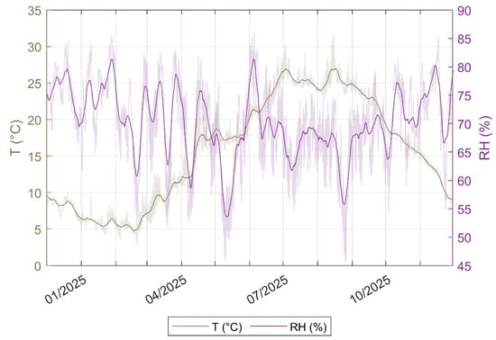
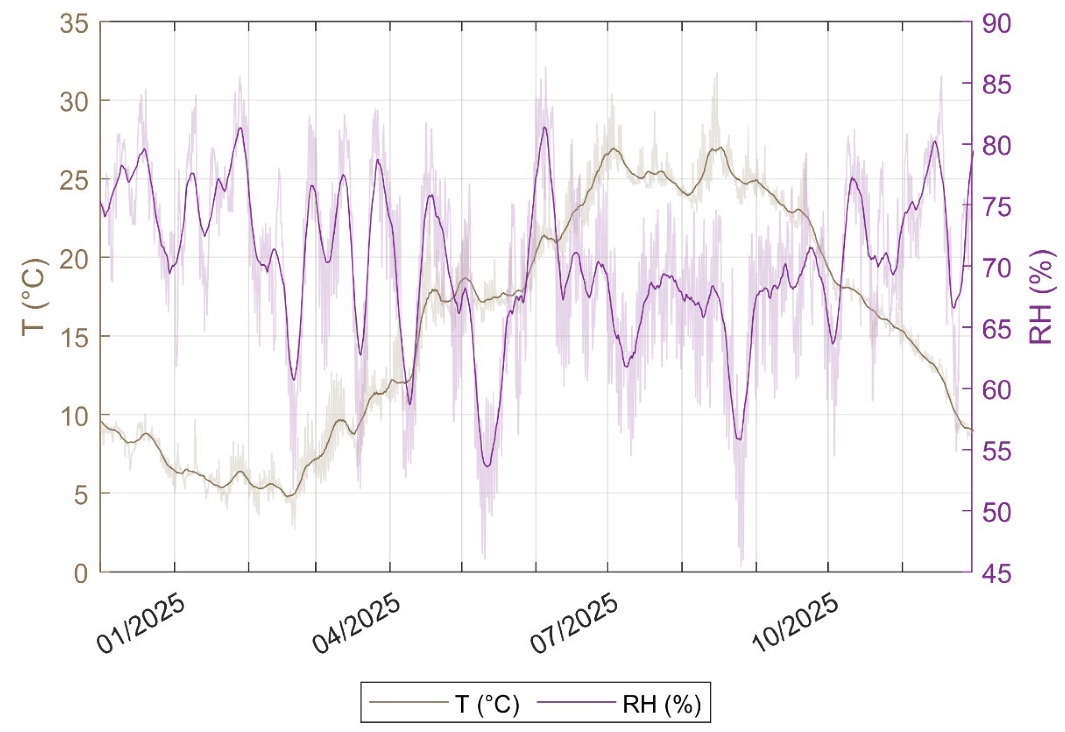
The measurement of environmental parameters took place over a total of 12 months, and an evaluation was subsequently carried out in connection with further exploratory activities monitoring the environment and the condition of the ceiling structure. Climatic data include measurements of relative humidity (RH), temperature (T), and moisture content (MC), recorded every hour in the period from 1 December 2024 to 30 November 2025. The average daily temperature (T) during the observed period ranged from 2.75 °C to 31.75 °C, with an overall average of 15.7 °C. The average daily relative air humidity (RH) during the observed period ranged from 38% to 93%, with an overall average of 70%. Increased relative humidity caused a subsequent rise in wood moisture, with the (RH) level usually being influenced by the duration of rainfall.
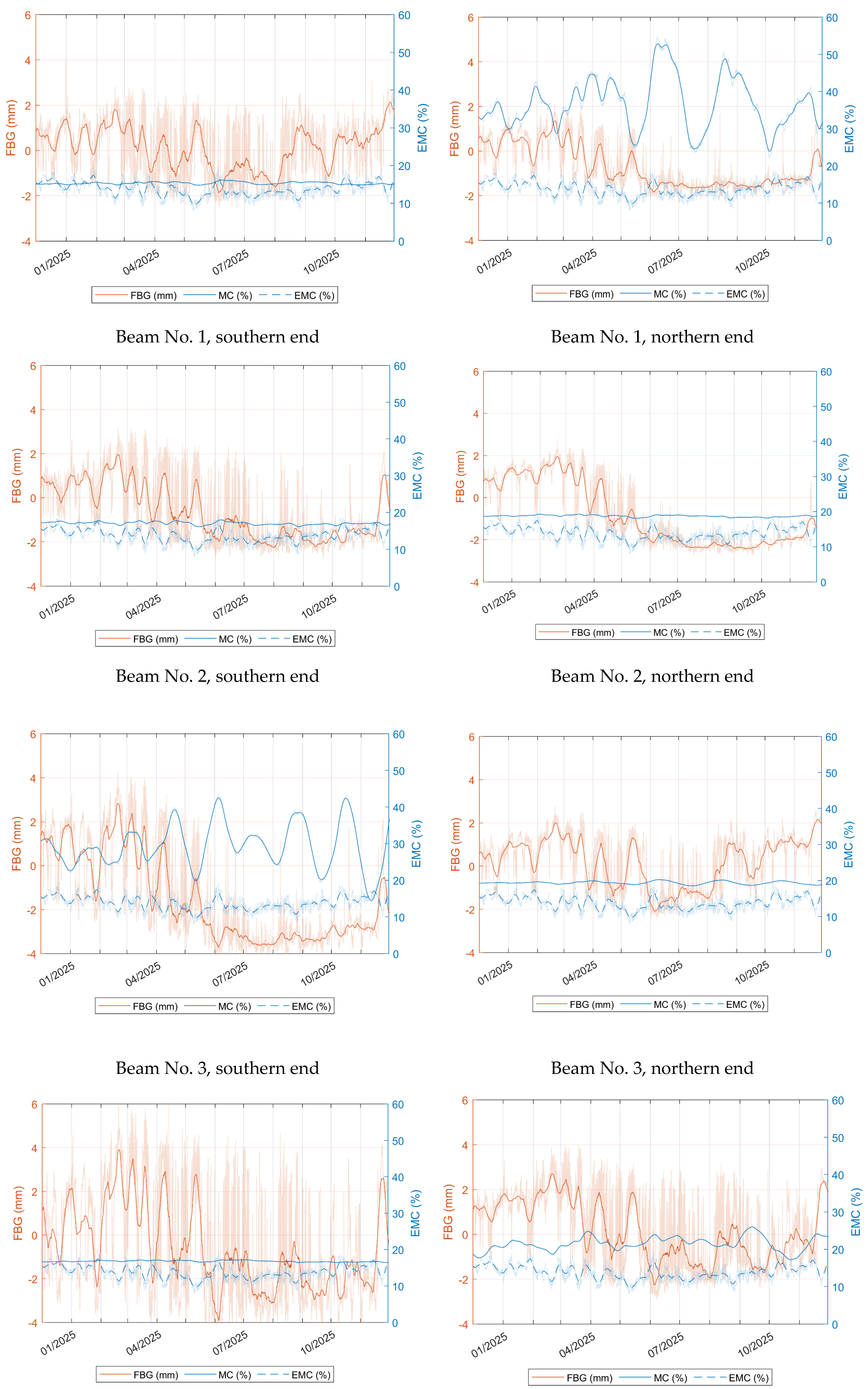
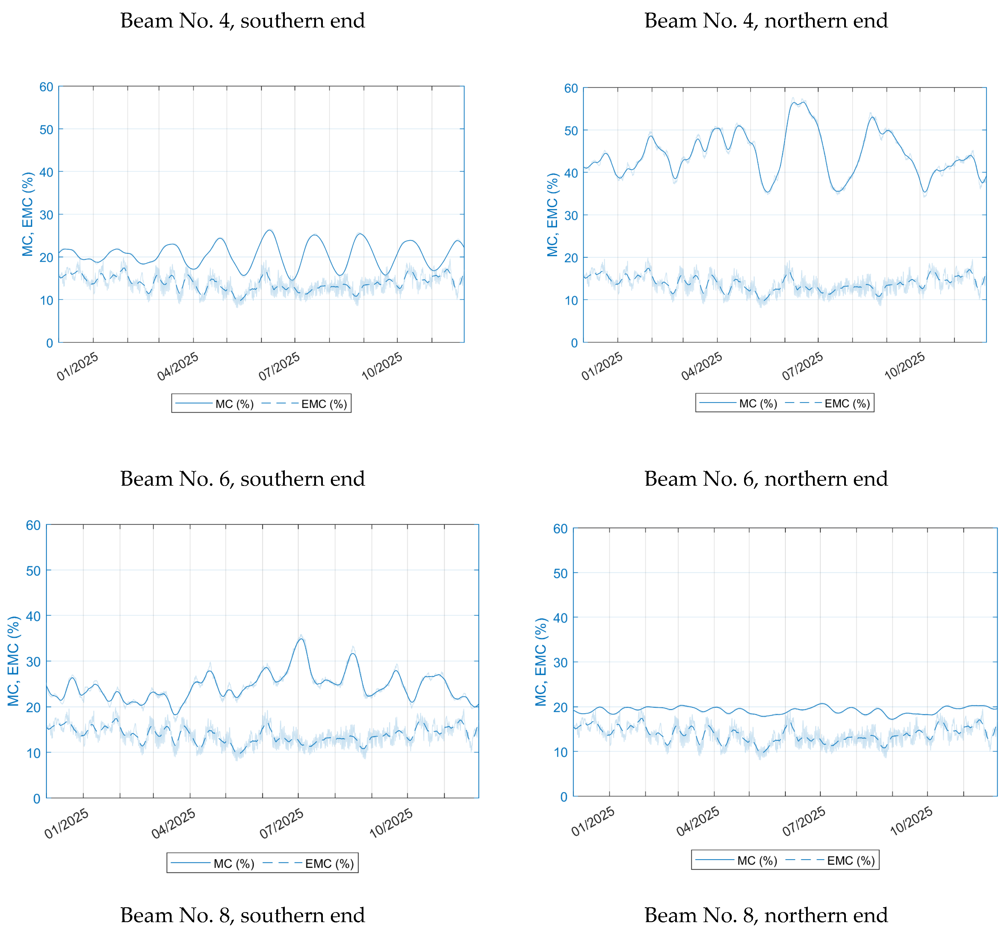
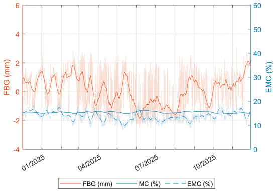
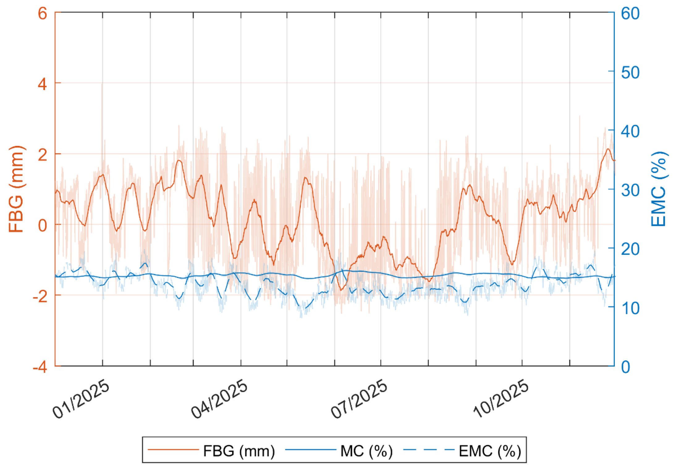
Climatic data (T, RH) were measured at 6 ceiling beam heads (no. 1, 4, 8), and moisture content (MC) was measured at 12 ceiling beam heads (no. 1, 2, 3, 4, 6, 8) (Figure 8). Measurements were taken once every hour. Deformation of the ceiling beams (FBG) was measured at eight ceiling beam heads (no. 1, 2, 3, 4) (Figure 8). Measurements were taken once every 3.5 s. The results of the climatic data (T, RH) measurements are shown in Figure 10, and the moisture content (MC) for selected ceiling beam heads are presented in Appendix A and illustrated with an example (Figure 11). The seasons can be clearly distinguished: winter with low temperatures from 2.75 to 10 °C and high relative humidity of 60–85%, summer with temperatures from 22 to 32 °C, and two transitional periods, spring and autumn, with an increase or decrease in temperature and relative humidity, respectively. Based on the monitoring of the movement of the contact surfaces of ceiling beams using point optical fiber Bragg grating (FBG) sensors, it is evident that no abutment undergoes significant irreversible damage. By combining measurements of physical properties with movement measurements, it was found that the beams remain in permanent deformation, although they continue to move within a transverse expansion range of 2 to 4 mm, depending on the microclimate. Under increased humidity, the wood swells and the beams appear to sink, and upon drying, they return.
Figure 10.
Results of the measurement of climate data (T, RH) from 1 December 2024 to 30 November 2025, measured for the northern and southern ends of ceiling beams no. 1, 4, 8.
Figure 11.
Results of wood moisture content (MC) measurements, equilibrium moisture content of wood (EMC), and movement of ceiling beams (FBG), in the period from 1 December 2024 to 30 November 2025, measured for the southern end of ceiling beam no. 1.
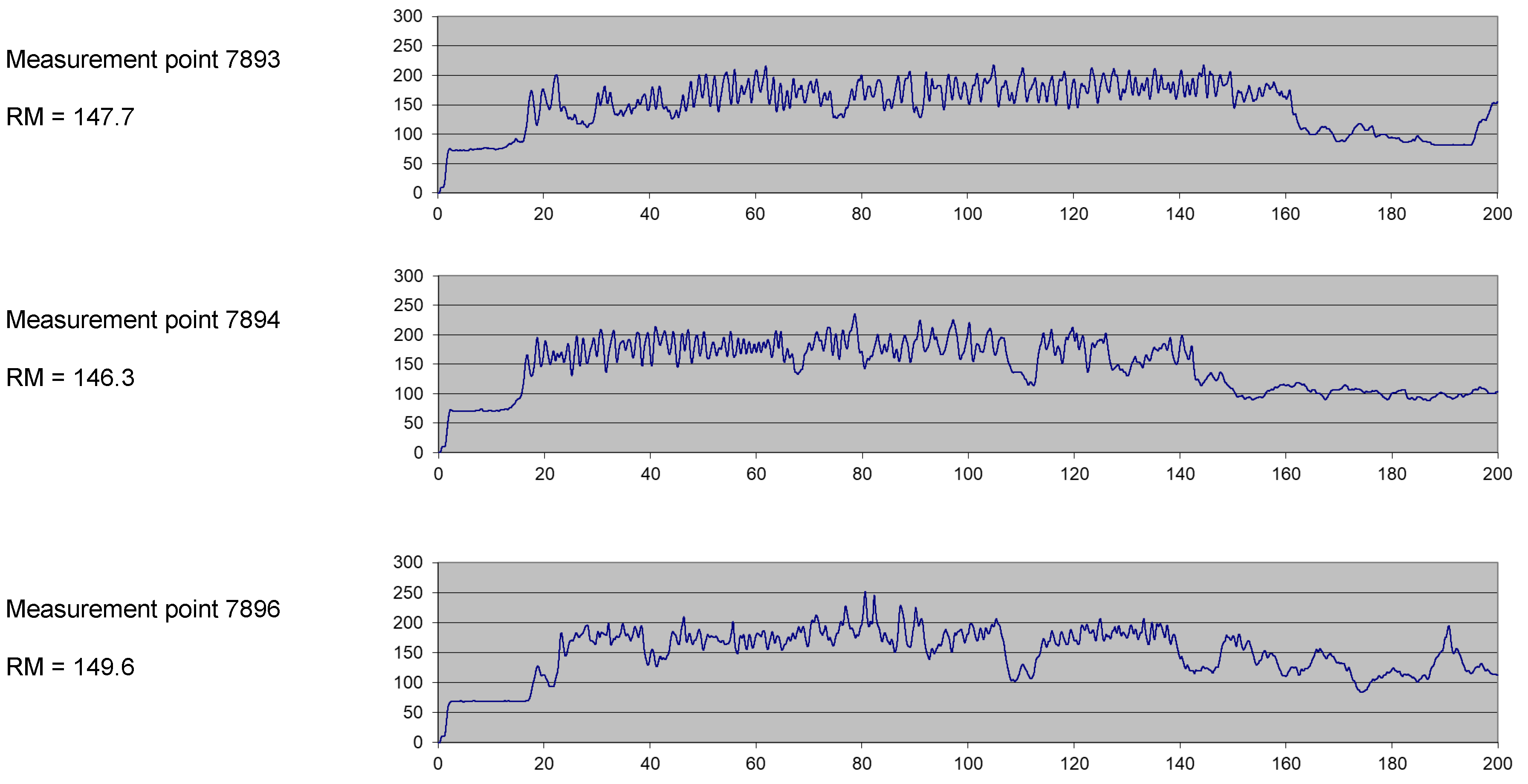
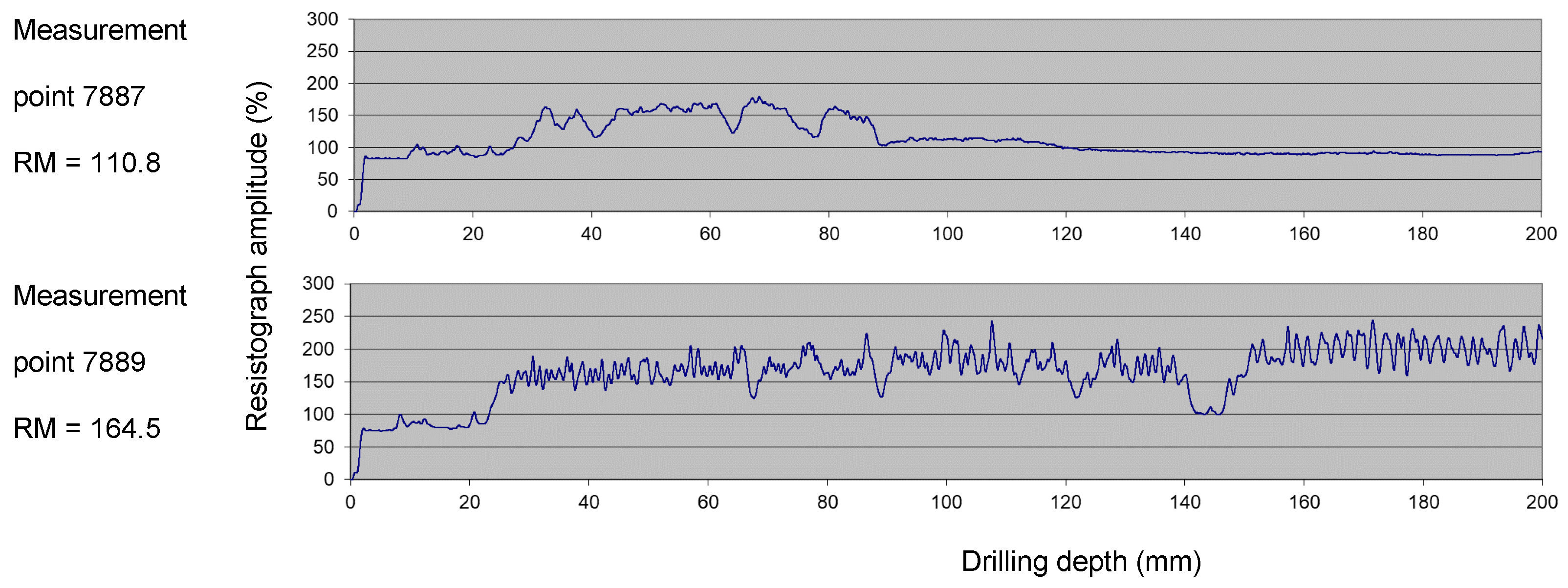
The output of the Resistograph measurement is a graphical record (density profile, dendrogram) corresponding to the energy consumed to maintain a constant drilling speed (y-axis) [13]. The x-axis represents the width of the beam. Peaks in the graphical record correspond to higher energy, indicating higher resistance and density, while lower points are associated with lower energy, lower resistance and density. The numbering of individual drills and their placement is schematically illustrated (Figure 12), and the RM results (resistance characteristics) calculated from the area under the curve and drilling depth are entered into the evaluation table for individual elements; see Table 1. An example of graphical records from individual measurement points using a drill is shown in Figure 13. When assessing the degree of damage, the authors use in their practice a scale from 1 to 4, where (1) means minimal infestation and (4) maximum infestation: (1) Slightly damaged element: well-dried structural elements, endoscopy drill smooth with clearly visible wood grain, without color changes or signs of biotic attack. (2) Moderately damaged element: well-dried structural elements, endoscopy drill smooth with clearly visible wood grain. In surface areas, there may be small signs of biotic damage—occasional bore tunnels of wood-eating insect larvae, spots with changed color due to decay. (3) Severely damaged element: Wood showing signs of biological attack, bore for endoscopy with splintered walls, traces of tunneling—presence of dust and debris from their filling, holes in the bore walls. Signs of wood-decay fungi—color change, cubical disintegration of the wood. Damage does not exceed 30% of the element’s cross-section. (4) Total destruction of the element: Wood severely damaged by wood-boring insects and rot; the element crumbles into dust and small skeletons, and in the case of rot into cubes of varying sizes. The color of the wood is dark. Remaining wood has limited material properties. Damage exceeds 30% of the element’s cross-section.
Figure 12.
Designation of places where the resistance characteristic (RM) was measured using a Resistograph drill, and the endoscopy for inspection anchoring depths (circles).
Table 1.
Results of the assessment of the condition of the ends of ceiling beams, evaluated according to the resistance characteristic (RM) obtained from measurements using a Resistograph drill—upper part with southern ends, bottom part with northern ends of beams.
Figure 13.
Example of measurement results from resistance drilling into the northern end of ceiling beam no. 2.
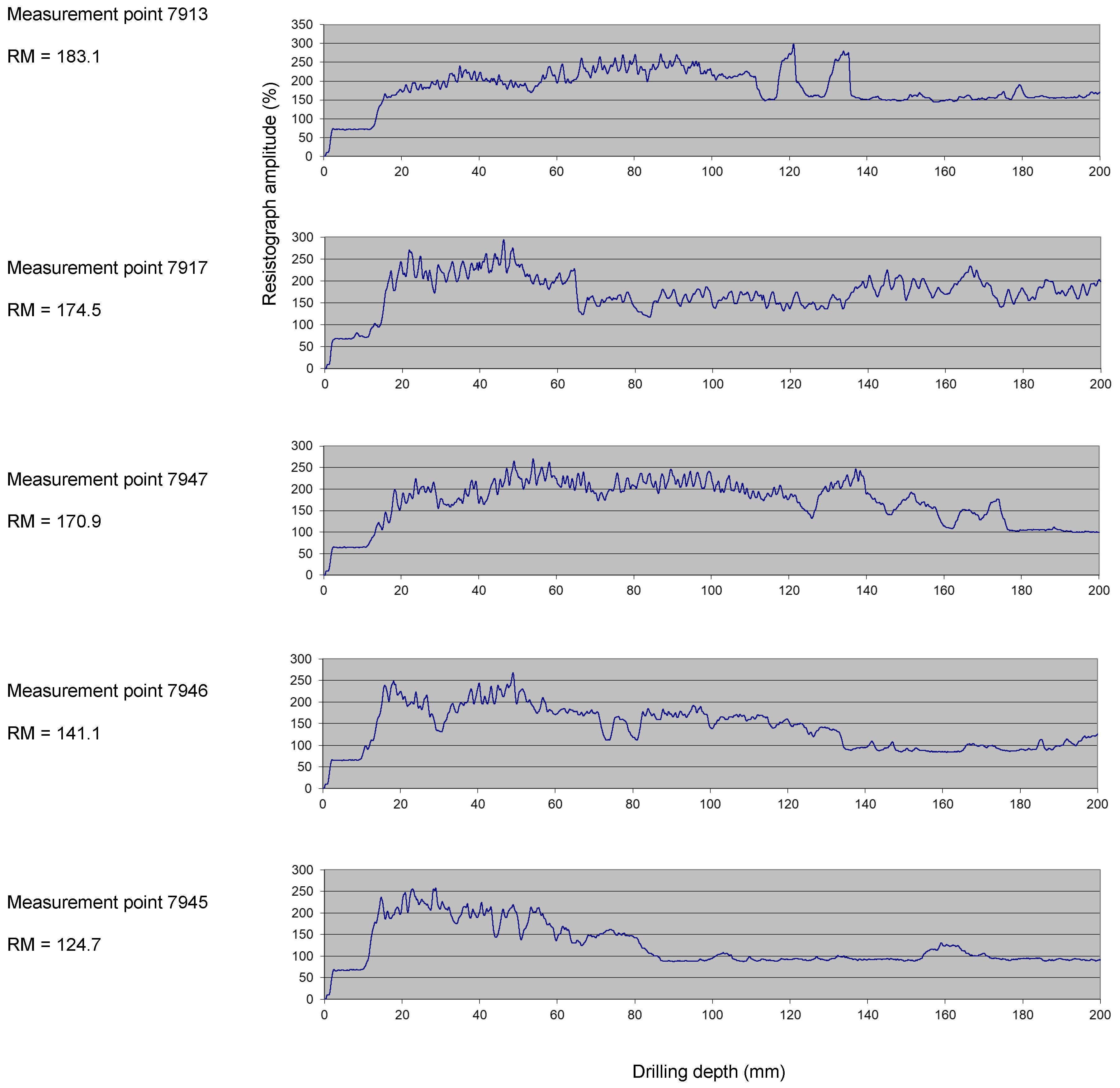
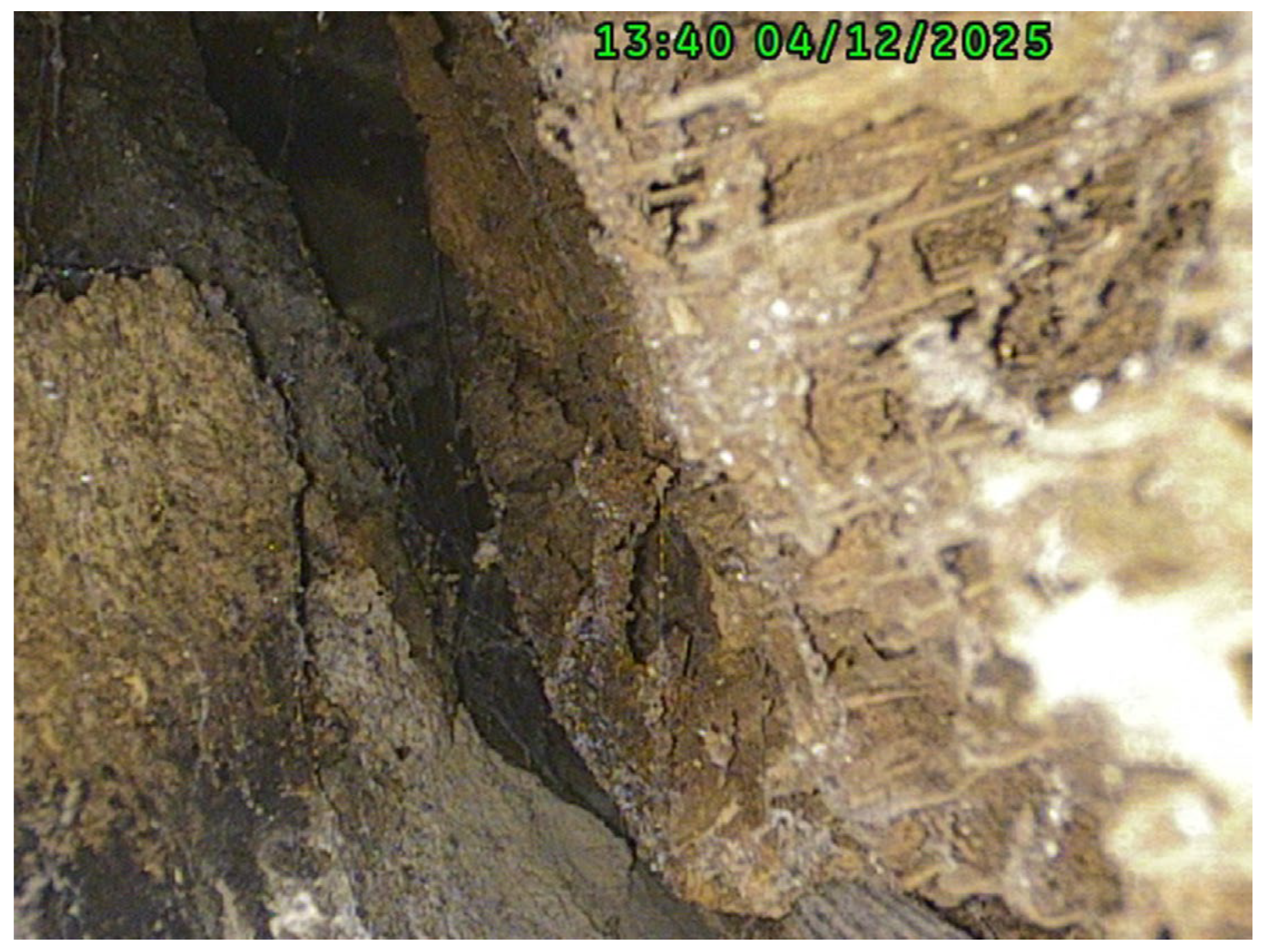
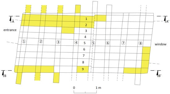
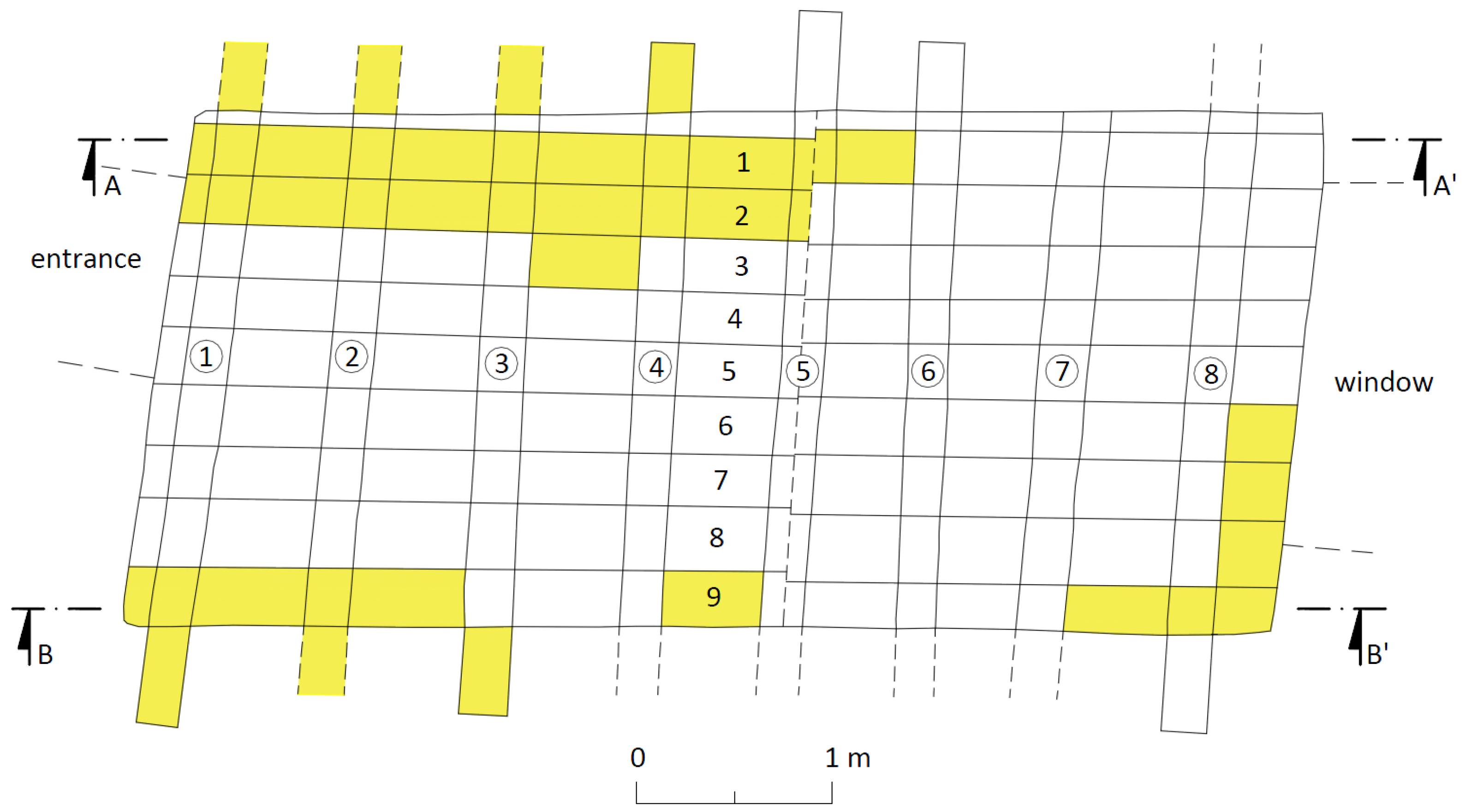
Therefore, for classification, all available in situ test results are combined, in this case including the extent of biological attack, micro-drilling results, and endoscopy results where available, e.g., Figure 14. The extent of biological attack is objectively assessed by the density of exit holes, with up to 25 holes per dm2 considered grade 2, 25–50 holes for grade 3, and more than 50 holes for grade 4. Micro-drilling results are used to support and adjust the above assessment, since the RM value is relative and depends on the type of wood and its moisture. Available measurement results on oak structures show a typical RM = 181.2 average value as the boundary between healthy and damaged wood [14]. The classification is not standardized and is used mainly as a guide for determining urgency and priorities of conservation actions. Measurements on walled-up sleepers showed that they are mostly in a condition comparable to the ceiling beams, (see Appendix B), with the northern sleeper being less damaged than the southern one, which is in a critical condition in the western part. The worst results were obtained on the decking boards, which are in places completely destroyed. The extent of serious damage is summarized in Figure 15.
Figure 14.
Example of endoscopy measurement results of the beam no. 7 northern end denoted as position 7.3.4 in Figure 12.
Figure 15.
Overview of critical degradation—elements most affected by biotic damage are marked in yellow.
4. Discussion
Long-term monitoring of historic wooden structures has mostly focused on their behavior in climate-controlled interiors [15]. This mainly involved churches, where heating was often installed, or buildings with valuable artistic decoration. The topic of this article adds to this spectrum by presenting previously unpublished observations of an ordinary building structure that has survived several centuries in conditions characterized by an unmodified environment or even influenced by the building being partially in ruins.
The moisture content of the wood (MC) in most ends of the ceiling beams ranged between 15% and 25%. It is true that the moisture content measured in the wood follows seasonal effective climate changes as described, for example, in [16,17,18]. The response is delayed, with smaller deviations depending on the contact of the sensors on the surface or inside the ceiling beam. The fluctuation of moisture content between summer and winter is practically up to 5%. Only at the northern ends of ceiling beams no. 1 and 6, and the southern ends of ceiling beams no. 3 and 8, was the wood moisture content (MC) measured higher at 25 to 55%. This phenomenon can be explained by the presence of liquid water either due to condensation on cooled metal electrodes or as a result of rainwater infiltration from an open terrace. The phase shift between the theoretically calculated equilibrium value (EMC) and the measured moisture content (MC) is minimal. In the literature, it is stated that the phase shift is directly related to the stiffness of the cell wall and structural changes of polymers in water binding [19]. Data from moisture sensors placed at a depth of 100 mm show less seasonal variation than typically observed by surface-located sensors. The moisture content curves are more evenly distributed and mutually more compact compared to the range of variations of the theoretically calculated equilibrium value (EMC). The measured moisture content in most sleepers is below 25%, the moisture level at which there is an increased risk of activation of wood-decaying fungi. Suitable conditions for the activation of wood-decay fungi start already from 20% [20,21].
The maximum dimension changes within a single beam are recorded within a range of 8 mm, always with a return based on the current environmental conditions. As temperature and relative humidity increase, the moisture content of the wood rises, and the beams swell and apparently move downward (negative values). With the opposite trend in physical properties, the wood shrinks (the beams return to their original position). The swelling and shrinking of solid ceiling beams correspond to fluctuations in climatic data and consequently the moisture content of the wood, e.g., [22,23]. Data from the literature was confirmed, which states that a 1% change in moisture corresponds approximately to a 0.25% change in dimension in the transverse direction [24].
Damage to the unique early Gothic ceiling structure in the eastern wing of Zvíkov Castle (specifically in the area under the sacristy) is caused by a combination of several negative factors that have led to its current critical condition. Neglected maintenance is the key factor that caused the development of rot and in many places led to the destruction of the wood. The source of moisture was mainly seepage from the adjoining terrace, dampening of the sacristy walls from water splashes from rain gutters, or direct penetration from the roof, which completely collapsed at the end of the 19th century. Condensation moisture and possibly rising damp, which may have been influenced by the application of unsuitable strengthening materials to the masonry in the 1970s, also play a role.
The structure is considerably infested by woodworm, which symbiotically accompanies brown rot. In some places, dried mycelia of wood-decaying fungi have also been identified. In ceiling oak beams, as well as in boarding planks, degradation mainly affects the younger sapwood near the surface of the elements. Additionally, the ceiling is burdened with a massive, approximately 35–50 cm thick historical fill (containing mortar, small stones, ceramic fragments, rubble) and two layers of fired paving. This permanent load amounts to approximately 7–9 kN per m2. Due to the damage to the wood substance and this loading, the beams gradually deform at their support points (heads).
Measurements of movements have shown that the ceiling beams continuously “work” depending on changes in temperature and relative humidity. As humidity increases, the wood swells and the beams move downwards; when drying, they shrink and return back. These cyclical volumetric changes (movements in the range of 2–4 mm) contribute to the mechanical stress of already weakened elements, to which a number of sources refer [25,26,27].
The most damaged parts are the ends of the ceiling beams, (especially the northern ends of beams no. 1–4 and the southern ends of beams no. 1–3), where significant deformations have occurred, while the beams in the span usually do not show overall sagging. This is due to the short span of 2.6 m. The serviceability limit criteria related to deflection are decisive for wooden ceilings only for spans greater than 2.5 m. For spans shorter than 2.5 m, on the other hand, the ultimate limit criteria, especially bending strength, are more critical. In engineering practice, this means that for such short ceiling spans, the structure will reach its strength limits before exceeding the allowed deflection limits [28]. The remaining ends of the ceiling beams are in better condition even though they are also affected by brown rot decay. The condition of the decking boards is worst near the walls. The most severely damaged elements of the ceiling structure are highlighted in yellow in the schematic diagram (Figure 14). The overall condition of the ceiling requires structural measures that will enable its stabilization in its preserved form.
5. Conservation Challenges
The conservation of this unique monument is a challenge as well as an opportunity to discuss the choice of further procedures. According to the authors of this article, the preserved monument is in a condition that requires an intervention based on a restoration approach. Engineers are advised not to try to restore the original state of the structure, but rather to extend its expected lifespan [29]. The ceiling is undoubtedly a technical monument with extraordinary values, and no other approach should be considered. Therefore, the rescue of the ceiling and ensuring its long-term preservation must be a priority. It is possible to discuss the regime of further activity within the building, where for centuries it has fulfilled the function of a horizontal load-bearing structure for people entering the affected spaces. This may be important for decisions regarding the intensity of the intervention or the adjustment of operational conditions.
Preserving historical monuments made up of various damaged elements is always associated with difficult decisions about which approach to take. The general principle of minimal intervention, recommended as a basic guideline, for example, in the updated version of the ISCARSAH Principles [30], means revealing and comparing the heritage value of the whole with the values of individual elements in relation to long-term protection and sustainability. There is no ideal approach recommended, as it depends on many factors, including the cultural and social environment in which the monument is located and also on how much courage the restorer has to deviate from strictly following the principle of minimal intervention. So, in this article, we open a discussion on whether in a given case it is better to dismantle the structure under expert supervision, documenting each step, and then reassemble it after consolidating the individual elements, or to support the existing structure against the risk of collapse, even if it means some inaccessible parts will not be treated and will deteriorate faster. In the second case, there are a number of technical options for supporting the structure. This article presents what the authors consider the optimal option, which visually hides the structure the least, allows visitors to see it, enables ongoing monitoring of its condition including adjustments to the supporting elements, and does not interfere with the historic wooden structure.
Tangible monuments are valuable creations of humans with unique individual characteristics, and this fact must be earnestly respected even during restoration. Just as we do not accept standardized procedures, materials, and technologies in technical solutions for monument preservation, we cannot regard the preserved ceiling as a two-dimensional structure. Therefore, we consider it optimal to devote attention to restoring each preserved beam as if each were an individual monument. Indeed, it is a monument with all aspects, including individual damage, which must be examined, individually treated, and the conditions adjusted in which the beam will function to prevent recurrence of damage or further degradation.
Such an approach necessarily requires opening the structure from above by gradually removing floor layers. Today’s documentation possibilities make it possible to ensure the preservation of the information contained in the floor strata, and new information can even be expected to be discovered when removing the layers. Moreover, this approach is the only effective one for the conservation of the most affected ripped floor beams. Although the proposed procedure may be unusual from a heritage conservation perspective, the valuable monument at Zvíkov deserves it.
David Yeomans, who places the choice between preserving the authenticity of the material and preserving the structural solution, presented the same view [31]. Preserving the authenticity of the material will mean that the structure is mostly restored on site, whereas preserving the structural solution will lead to the partial or complete dismantling and reassembly of the structure. The engineer should use their skills to understand the values of historical structures and technologies and during the design phase should collaborate with other heritage conservation experts. During implementation, we recommend supporting the ceiling, for example, with a king post scaffold.
The next step in saving this monument is the necessity to create conditions for a long-lasting continued life as possible. That is, to ensure a suitable environment in terms of fluctuations in humidity and temperature (because of moisture) and air movement in the space around the wooden elements. This environmental conservation approach has proven to be the most optimal and most successful. It means adjusting the climate of the space around the wooden elements. To propose suitable environmental protection strategies for historical elements of historic buildings, publications that deal with the subject can be used, for example, [32,33] (Bienvenido-Huertas, Rubeis, Silva). Monitoring has shown that the structure withstands higher temperature fluctuations quite well; therefore, air conditioning could focus mainly on humidity parameters. The use of solar energy is also an option, if it is necessary to ensure forced operation.
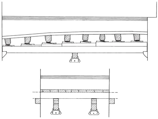
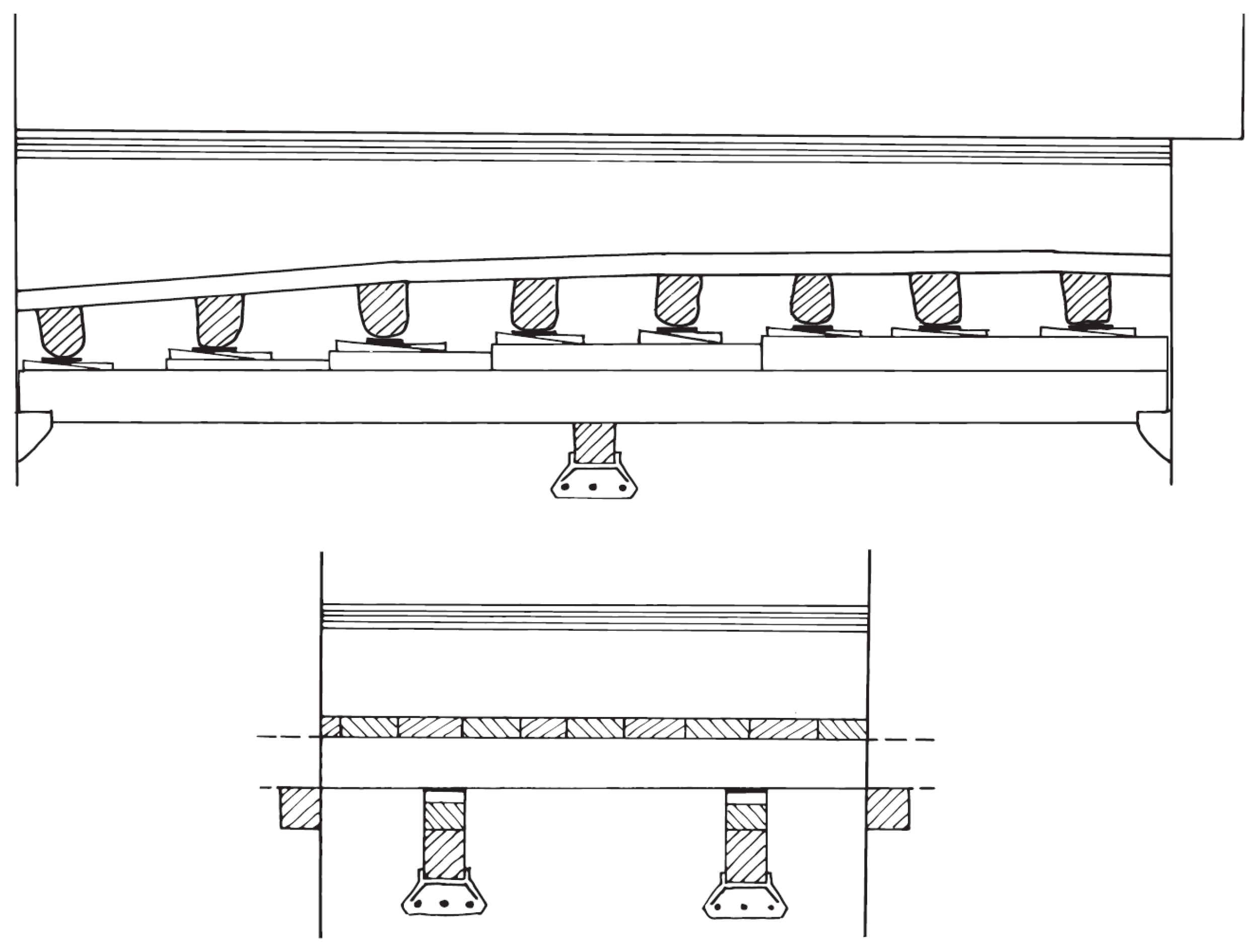
If dismantling and reassembling the ceiling would be unacceptable to heritage bureaucrats, it will be necessary to adopt an engineering approach and support the ceiling from underneath. The undeniable advantage of stabilizing the ceiling from below is preserving the authenticity of the entire structure, including the layering of two layers of baked tiles with a leveling layer placed on a thick layer of fill. The disadvantage of bottom support will be the gradual transfer of the total weight of the ceiling structure onto the supporting beams; additionally, it will be necessary to support the decking boards, which are also significantly damaged near the walls. Despite the greatest care, sooner or later there will be gradual imprints of the contact material into the original elements, primarily the ceiling beams, which in most cases are left on the underside as round timber without trimming the sapwood. Moreover, the outer sapwood parts of the beams are significantly damaged, not to mention that possible biotic changes at the points where the original elements are supported by new material cannot be predicted. In any case, a reduction in the lifespan of this monument should be expected compared to the restoration procedure. There are a number of ways to technically implement the support. For illustration, let us present one proposal, which uses the installation of two longitudinal beams (runners) on forged brackets anchored to the masonry. The longitudinal beams should be placed parallel, approximately 50 cm from the face of the wall, to allow sufficient access to all elements of the original structure, primarily the heads of the ceiling beams. Due to the possible deflection of the longitudinal runners, the structure is supplemented with a central transverse girder also mounted on forged brackets anchored to the masonry (Figure 16). Secondary beams can be placed on the runners to support the decking boards.
Figure 16.
Proposal for supporting the ceiling using a longitudinal runner with a central girder.
Author Contributions
Conceptualization, M.K. and P.M.; methodology, M.K. and P.M.; data processing P.D. and M.K.; writing—original draft preparation, M.K. and M.D.; writing—review and editing, M.K. and M.D.; visualization, J.B.; supervision, M.D.; project administration, M.K.; funding acquisition, M.K. All authors have read and agreed to the published version of the manuscript.
Funding
Monitoring was funded by the National Heritage Institute in Prague, No. 3012G1240004.
Data Availability Statement
The raw data supporting the conclusions of this article will be made available by the authors on request.
Acknowledgments
The authors acknowledge support of the project “Wooden structures prevention and maintenance for heritage conservation purposes” NAKI III, reg. No. DH23P03OVV005 provided by the Ministry of Culture of the Czech Republic and the RVO 68378297, and thank to Marek Eisler for English correction.
Conflicts of Interest
The funders had no role in the design of the study; in the collection, analyses, or interpretation of data; in the writing of the manuscript; or in the decision to publish the results:
Abbreviations
The following abbreviations are used in this manuscript:
| MC | Moisture content |
| EMC | Equilibrium moisture content |
| RH | Relative humidity |
| T | Temperature |
| FBG | Fiber Bragg grating |
| RM | Resistance drilling characteristics |
Appendix A
Results of environmental measurements in the period from 1 December 2024 to 30 November 2025.
Figure A1.
Environmental measurements on selected beam ends.
Appendix B. Results of Resistance Drilling Measurements
Figure A2.
Resistance drilling measurements on the northern sleeper.
References
- Záruba, F. Hrady Doby Přemyslovské I. Královské Hrady, Biskupská Sídla, Chebsko; NLN: Praha, Czech Republic, 2023. [Google Scholar]
- Záruba, F. Hradní Kaple I. Doba Přemyslovská; Unicornis: Praha, Czech Republic, 2014. [Google Scholar]
- Tampone, G. Il Restauro delle Strutture di Legno: Il Legname da Costruzione, le Strutture Lignee e il Loro Studio, Restauro, Tecniche di Esecuzione del Restauro; Hoepli: Milano, Italy, 1996. [Google Scholar]
- Unger, A.; Schniewind, A.; Unger, W. Conservation of Wood Artifacts; Springer: Berlin/Heidelberg, Germany, 2001. [Google Scholar]
- Majumder, M.; Gangopadhyay, T.K.; Chakraborty, A.K.; Dasgupta, K.; Bhattacharya, D.K. Fibre Bragg gratings in structural health monitoring—Present status and applications. Sens. Actuators A Phys. 2008, 147, 150–164. [Google Scholar] [CrossRef] [Scilit]
- Münster, P.; Prinosil, J.; Helan, R.; Sifta, R.; Horvath, T. Modular FBG based technical textile for temperature and strain monitoring. In Proceedings of SPIE—The International Society for Optical Engineering; SPIE: Bellingham, WA, USA, 2021; Volume 11772. [Google Scholar]
- Reinprecht, L. Wood Deterioration, Protection and Maintenance; John Wiley & Sons: Hoboken, NJ, USA, 2016. [Google Scholar]
- Tannert, T.; Anthony, R.; Kasal, B.; Kloiber, M.; Piazza, M.; Riggio, M.; Rinn, F.; Widmann, R.; Yamaguchi, N. Recommendation of RILEM TC 215-AST: In-situ assessment of structural timber using semi-destructive techniques. Mater. Struct. 2014, 47, 759–766. [Google Scholar]
- Nowak, T.; Patalas, F.; Karolak, A. Estimating Mechanical Properties of Wood in Existing Structures—Selected Aspects. Materials 2021, 14, 1941. [Google Scholar] [CrossRef] [Scilit] [PubMed]
- Sharapov, E.; Brischke, C.; Militz, H. Assessment of Preservative-Treated Wooden Poles Using Drilling-Resistance Measurements. Forests 2020, 11, 20. [Google Scholar]
- Azzi, Z.; Al Sayegh, H.; Metwally, O.; Eissa, M. Review of Nondestructive Testing (NDT) Techniques for Timber Structures. Infrastructures 2025, 10, 28. [Google Scholar] [CrossRef] [Scilit]
- Fuchs, A.; Schreyer, A.; Feuerbach, S.; Korb, J. A new technique for termite monitoring using computer tomography and endoscopy. Int. J. Pest Manag. 2004, 50, 63–66. [Google Scholar] [CrossRef] [Scilit]
- Kloiber, M.; Drdácký, M.; Machado, J.S.; Piazza, M.; Yamaguchi, N. Prediction of mechanical properties by means of semi-destructive methods: A review. Constr. Build. Mater. 2015, 101, 1215–1234. [Google Scholar] [CrossRef] [Scilit]
- Kloiber, M.; Bláha, J.; Václavík, F.R.; Růžička, P.; Kunecký, J. Modern diagnostic methods and traditional carpentry techniques used for the renovation of the white tower belfry in Hradec Kralove. In Structural Health Assessment of Timber Structures; TTP: Wroclaw, Poland, 2015; pp. 260–271. [Google Scholar]
- Bienvenido-Huertas, D.; León-Muñoz, M.; León-Muñoz, J.J.; Rubio-Bellido, C. Analysis of climate change impact on the preservation of heritage elements in historic buildings with a deficient indoor microclimate in warm regions. Build. Environ. 2021, 200, 107959. [Google Scholar] [CrossRef] [Scilit]
- Niklewski, J.; van Niekerk, P.B.; Meyer-Veltrup, L.; Sandak, J.; Brischke, C. Modelling wood moisture content in outdoor conditions from measured data. In Proceedings of the IRG55 Scientific Conference on Wood Protection, Knoxville, TN, USA, 19–23 May 2024; Volume 2024. [Google Scholar]
- Richards, J.; Brimblecombe, P. Moisture as a Driver of Long-Term Threats to Timber Heritage—Part I: Changing Heritage Climatology. Heritage 2022, 5, 1929–1946. [Google Scholar] [CrossRef] [Scilit]
- Brischke, C.; Thelandersson, S. Modelling the outdoor performance of wood products—A review on existing approaches. Constr. Build. Mater. 2014, 66, 384–397. [Google Scholar] [CrossRef] [Scilit]
- Johannesson, B.; Janz, M. A two-phase moisture transport model accounting for sorption hysteresis in layered porous building constructions. Build. Environ. 2009, 44, 1285–1294. [Google Scholar] [CrossRef] [Scilit]
- Meyer, L.; Brischke, C. Fungal decay at different moisture levels of selected European-grown wood species. Int. Biodeterior. Biodegrad. 2015, 103, 23–29. [Google Scholar] [CrossRef] [Scilit]
- Isaksson, T.; Thelandersson, S. Experimental investigation on the effect of detail design on wood moisture content in outdoor above ground applications. Build. Environ. 2013, 59, 239–249. [Google Scholar] [CrossRef] [Scilit]
- Nopens, M.; Riegler, M.; Hansmann, C.; Krause, A. Simultaneous change of wood mass and dimension caused by moisture dynamics. Sci. Rep. 2019, 9, 10309. [Google Scholar] [CrossRef] [Scilit] [PubMed]
- Siau, J.F. Transport Processes in Wood; Springer: Berlin/Heidelberg, Germany, 1984. [Google Scholar]
- Arriaga, F.; Peraza, F.; Esteban, M.; Bobadilla, I.; García, F. Intervención en Estructuras de Madera; AITIM: Madrid, Spain, 2002; p. 464s. [Google Scholar]
- Uwizeyimana, P.; Perrin, M.; Laügt, E.; Eyma, F. Durability study of glulam timber under cyclic moisture loading. Constr. Build. Mater. 2021, 315, 125715. [Google Scholar]
- Gao, Y.; Fu, Z.; Zhou, Y.; Gao, X.; Zhou, F.; Cao, H. Moisture-Related Shrinkage Behavior of Wood at Macroscale and Cellular Level. Polymers 2022, 14, 5045. [Google Scholar] [CrossRef] [Scilit] [PubMed]
- Stanciu, M.D.; Teodorescu, H.D.; Vlase, S. Degradation of Mechanical Properties of Pine Wood Under Symmetric Axial Cyclic Loading Parallel to Grain. Polymers 2020, 12, 2176. [Google Scholar] [CrossRef] [Scilit] [PubMed]
- Unuk, Ž.; Premrov, M.; Žegarac Leskovar, V. A brief insight into timber floors in Slovenia with a numerical case study of an existing timber floor. Int. J. Constr. Res. Civ. Eng. 2017, 3, 11–19. [Google Scholar] [CrossRef] [Scilit]
- Yeomans, D. The safety of historic structures. Struct. Eng. 2006, 84, 18–22. [Google Scholar]
- ICOMOS Charter—Principles for the Analysis, Conservation and Structural Restoration of Architectural Heritage. 2003. Available online: http://www.international.icomos.org (accessed on 5 July 2026).
- Yeomans, D.T. Repairs to historic timber structures: Changing attitudes and knowledge. In Structural Analysis of Historic Construction; D’Ayala, D., Fodde, E., Eds.; Taylor & Francis Group: Bath, UK, 2008; pp. 63–70. [Google Scholar]
- Rubeis, T.; Nardi, I.; Muttillo, M.; Paoletti, D. The restoration of severely damaged churches—Implications and opportunities on cultural heritage conservation, thermal comfort and energy efficiency. J. Cult. Herit. 2020, 43, 186–203. [Google Scholar] [CrossRef] [Scilit]
- Silva, H.E.; Henriques, F.M.A. Microclimatic analysis of historic buildings: A new methodology for temperate climates. Build. Environ. 2014, 82, 381–387. [Google Scholar] [CrossRef] [Scilit]

Disclaimer/Publisher’s Note: The statements, opinions and data contained in all publications are solely those of the individual author(s) and contributor(s) and not of MDPI and/or the editor(s). MDPI and/or the editor(s) disclaim responsibility for any injury to people or property resulting from any ideas, methods, instructions or products referred to in the content. |
© 2026 by the authors. Licensee MDPI, Basel, Switzerland. This article is an open access article distributed under the terms and conditions of the Creative Commons Attribution (CC BY) license.