


Abstract
This study investigates amorphous anodized porous TiO2 (a-TiO2) as a substrate for iridium-based oxygen evolution catalysts. The substrates were prepared via anodization of Ti foil in a glycerol-based solution for 15 min @ 60 V. Nickel was subsequently electrodeposited to act both as a conductive and sacrificial layer for the galvanic deposition of iridium from an Ir(IV) chloro-complex solution. Electrochemical anodization resulted in a uniform IrOx layer on the a-TiO2 substrate, featuring Ir aggregates ~250 nm in size and an Ir:Ni atomic ratio of ca. 7, as determined by EDS analysis. The quantity of Ni determined by ICP-MS bulk analysis indicated that Ni resided also within the porous matrix. Varying the Ni deposition charge density (qNi) revealed that an intermediate loading (1463 mC cm−2) provided the best balance between Ir accessibility during the galvanic replacement step and electronic continuity. The optimized IrOx/Ir-Ni/a-TiO2 electrode achieved excellent OER performance (η = 344 mV @ 10 mA cm−2; 1.68 mA μgIr−1 @ η = 300 mV) at an ultra-low Ir loading of 2.15 μgIr cm−2 and demonstrated good short-term stability, with only a 20 mV potential increase over 4 h of continuous operation at 5.5 mA cm−2. Overall, this strategy offers a scalable pathway for producing efficient OER electrodes with minimal noble metal loading.
1. Introduction
The oxygen evolution reaction (OER) is a key anodic process relevant to many industrial electrochemical applications [1]. In water electrolysis, OER takes place at the anode, producing protons and electrons, which subsequently recombine at the cathode to produce hydrogen [2]. In addition, OER is the counter electrode reaction at the anode during metal electrodeposition or the recovery of heavy, toxic or precious metals, where metal ions are reduced and deposited at the cathode [3,4,5]. However, the OER has a complex mechanism and sluggish kinetics, which lead to high overpotential and thus elevated operating voltages, thereby hindering its efficiency and scalability in industrial applications [6,7,8]. Currently, iridium oxide is regarded as the benchmark catalyst for the OER, and it is widely used in the industry in the form of Dimensionally Stable Anodes (DSAs), which are well known for their durability and performance [9,10]. Nevertheless, iridium’s scarcity and consequently its high cost necessitate (apart from efficient recycling [11,12,13]) reducing its loading while maintaining catalytic activity and long-term stability [14]. This can be achieved by depositing ultrathin, continuous IrO2 films [15] or highly dispersed nanoparticles onto high-surface-area substrates that exhibit high stability and corrosion resistance, such as titanium dioxide [16,17,18].
A major limitation of TiO2 is its low electrical conductivity, which can be mitigated through strategies such as intrinsic modifications or interface engineering [19]. Intrinsic modifications can be achieved through hydrogenation (introducing oxygen vacancies) [20], chemical or electrochemical reduction (partially reducing Ti4+ to Ti3+) [21,22], or doping with foreign elements that alter the band structure and enhance electrical properties [23]. Interface engineering approaches employ TiO2 as a template for the integration of conductive catalyst films or interlayers. This can be accomplished in two main ways: (1) densely decorating the TiO2 surface with catalyst nanoparticles to form a continuous, conductive catalyst film; or (2) introducing a conductive metal interlayer that functions as a current collector between TiO2 and the catalyst [24,25]. The latter approach can be implemented using various techniques, including hydrothermal treatments [26], dip coating [27], chemical vapor deposition (CVD) [28], or electrodeposition [29]. In comparison to other methods, electrodeposition offers a simple, fast and low-cost route for fabricating metallic layers or nanoparticles and it is well-established in the industry. By adjusting parameters such as applied potential/current, deposition time, and bath composition, different deposits with various nanoparticle sizes, morphologies, and compositions can be obtained [30,31,32].
Beyond its use for direct metal deposition, electrodeposition can also be used to enable galvanic replacement reactions on metal layers; a technique that facilitates the formation of more noble metal structures through spontaneous redox reactions [33]. In this process, the electrodeposited metal layer functions not only as a current collector but also as a sacrificial layer that undergoes partial dissolution while being simultaneously replaced by a more noble metal. Galvanic replacement is a simple, scalable, and cost-effective method for producing nanoscale catalytic layers or ultrathin coatings, which are widely employed in various electrochemical applications [34].
In the context of oxygen evolution electrocatalysis, galvanic replacement has been explored for the fabrication of platinum-group metal (PGM) catalysts, particularly iridium-based materials [35,36,37,38,39]. Provided that the standard redox potential of the non-noble metal is more negative than that of iridium, various metals, such as copper, cobalt, iron, and nickel, can serve as sacrificial layers. Among them, nickel has emerged as the most promising due to its ability to tune/modify the electronic structure of iridium oxide and enhance its intrinsic electrocatalytic activity and stability towards the OER [40,41,42].
Over the past few years, several studies have reported the fabrication of Ir-Ni electrocatalysts via galvanic replacement [36,37,38,39,43,44,45], highlighting the synergistic effects between the two metals and their potential to reduce iridium loading while maintaining or even improving the activity and stability. These catalysts have been supported on a variety of substrates, including glassy carbon (GC) [36,38,39], gold (Au) [37], and titanium (Ti) foil [43]. While these materials enable fundamental studies, they present several limitations for long-term operation under acidic and oxidative conditions. GC, for instance, suffers from oxidative degradation at high anodic potentials [46], whereas Au is costly and not viable for large-scale applications. Titanium, although corrosion-resistant, rapidly forms a passivating TiO2 layer that limits its conductivity unless modified [16].
In our previous work, we addressed this challenge by using high aspect-ratio, close-packed crystalline TiO2 nanotube arrays (both reduced and as-prepared) as the substrate for Ir-based OER catalysts [45]. Nickel was electrodeposited to enhance electronic conductivity (for as-prepared samples) and to serve as a sacrificial layer for galvanic replacement by Ir. While this approach enabled the formation of highly active catalysts, it required a multi-step fabrication process, including two-step anodization to create ordered nanotube arrays and a high-temperature annealing step to crystallize the TiO2. These steps increased energy consumption and the overall complexity of electrode preparation, while the high Ni loading often led to pore clogging.
Building on these findings, the present work introduces a simpler and more scalable strategy. Instead of annealed nanotube arrays, a short, single-step anodization is used to produce amorphous porous TiO2 (a-TiO2) that is used in its as-prepared state without further treatment, eliminating the energy-intensive annealing step. Furthermore, substantially lower Ni loadings are employed to mitigate clogging while still providing adequate conductivity and serving as a sacrificial metal for Ir deposition via galvanic replacement. This refined approach allows for ultra-low Ir loading while maintaining high activity towards the OER, addressing both cost and scalability challenges. Here, we investigate how optimizing the amount of electrodeposited Ni influences Ir deposition, surface electrochemistry, and catalytic activity, providing insights into optimizing this simplified electrode fabrication route.
2. Materials and Methods
2.1. Fabrication of the Substrate
Ti foil (0.25 mm thick, 99.5%, Thermo Fisher Scientific, Waltham, MA, USA) was cut into 1 × 1 cm2 pieces and was ultrasonically cleaned in ethanol, acetone and doubly distilled (d.d.) H2O for 10 min consecutively. The cleaned foils were then left to dry in air. For the formation of a porous TiO2 structure on the Ti foil, a short anodization procedure was followed, using Pt foil as the cathode and the Ti foil as the anode. The anodization electrolyte was a glycerol-based solution composed of 10 wt.% H2O, 0.5 wt.% NH4F. The applied voltage was 60 V for 15 min, using a laboratory power supply (DP60-15H, DSC Electronics, Bonn, Germany), and the temperature was kept at 18 °C using a jacketed cell connected to a tap water circulation system. The anodized Ti foils remained in a fresh anodization solution for at least 1 h, to improve the adhesion of the anodized film on the Ti foil [47]. They were then rinsed with d.d. H2O and left to dry in air. The anodized foils were used in their as-prepared amorphous state (a-TiO2).
2.2. Fabrication of the Electrocatalysts
Prior to nickel electrodeposition, a short cathodic potential pulse was applied to the substrate equal to −1.45 V vs. RHE in 1 M NH4SO4 neutral solution for 3 sec, to temporarily enhance the conductivity of the semiconducting TiO2 by inducing Ti3+ states [29]. This conductivity “switch” originates at the TiO2/Ti interface, i.e., the bottom of the porous TiO2 film in contact with the Ti foil, thereby creating favorable conditions for nickel nucleation [48]. Due to the lower overpotential at this interface, nickel deposition is expected to initiate at the bottom of the porous TiO2 layer and progress toward the top.
Immediately after this short cathodization step, the substrate was transferred to a Watt’s-type bath (30 g NiSO4·6H2O, 2.8 g NiCl2·6H2O, 4 g H3BO3 in 100 mL d.d. H2O), with Pt foil as the counter electrode and Saturated Calomel Electrode (SCE) as the reference electrode. The temperature was maintained at 50 °C, and magnetic stirring was applied during the process. Nickel was electrodeposited by using a pulsed-current technique consisting of a cathodic step (−70 mA cm−2, 10 ms), an anodic step (+70 mA cm−2, 1 ms), and a relaxation step (0 mA cm−2, 10 s) [49]. Pulsed electrodeposition, instead of constant current, promotes the formation of a more uniform nickel film. The total amount of deposited nickel was controlled by adjusting the number of deposition cycles, from which the corresponding charge density (qNi) was calculated. Electrodepositions were carried out for 1161, 2322, and 4644 cycles, corresponding to qNi values of 731, 1463, and 2926 mC cm−2, respectively.
After electrodeposition, the Ni/a-TiO2 electrodes were rinsed briefly with d.d. H2O to remove residual Watt’s bath components and immediately immersed in a N2-purged iridium precursor solution (1 mM K2IrCl6, 1 mM HCl) at 65 °C for 15 min for the galvanic replacement reaction to take place [36]. An N2 blanket was maintained over the solution to prevent oxygen ingress during the transmetallation process. The resulting Ir/Ni/TiO2 electrodes were then converted to IrOx/Ir-Ni/a-TiO2 by electrochemical anodization of metallic Ir into its stable porous IrOx oxides [34,50]. This was achieved by potential cycling in an acidic electrolyte (0.1 M HClO4) at a high scan rate (200, 100 and 50 mV s−1), which simultaneously promoted the dissolution of exposed and/or unreacted Ni [43,51]. The lower potential vertex was set at the onset of H2 evolution, while the upper vertex was increased from +0.3 VSCE to +0.9 VSCE and finally to +1.2 VSCE, until stable voltammetry was recorded.
2.3. Electrochemical Set-Up and Procedures
Electrochemical measurements were performed in a three-electrode configuration, using the prepared electrodes as the working electrode, Pt foil as the counter electrode, and SCE as the reference. Experiments were carried out at room temperature with an Autolab PGSTAT302N potentiostat/galvanostat (Eco Chemie, Utrecht, The Netherlands) controlled through NOVA 2.1.4 software (Eco Chemie, Utrecht, The Netherlands).
The surface electrochemistry of the catalysts was first examined by cyclic voltammetry (CV) in 0.1 M HClO4 deaerated electrolyte, at a scan rate of 200, 100 and 50 mV s−1, over three progressively wider potential windows. In the initial window (−0.3 V to +0.3 VSCE), dissolution of residual Ni occurred along with the formation of an Ir(Ni) core–shell arrangement [36,38]. After rinsing, the electrode was transferred into a fresh, N2 purged electrolyte, where the second potential window (−0.3 V to +0.9 VSCE) promoted the reversible formation of Ir(III)/Ir(IV) oxides and hydroxides. Finally, in the extended range (−0.3 V to +1.2 VSCE), Ir was electrochemically oxidized to higher valence states (Ir(IV)/Ir(V)), leading to the formation of a porous, stable 3D IrOx layer [52].
OER activity was assessed by linear sweep voltammetry (LSV) between +0.9 and +1.4 VSCE at 5 mV s−1. To correct for uncompensated resistance and ohmic losses, the current-interrupt method was applied at 100 mV intervals within the +0.9 to +1.3 VSCE potential region. To further validate the activity and minimize mass-transport limitations, the most active electrode was also adapted into a rotating disk electrode (RDE) configuration (CTV 101T, Tacussel, France) and tested under rotation at 1600 rpm. Finally, short-term electrode stability was evaluated under static conditions by chronopotentiometry at a constant current density of 5.5 mA cm−2 for 4 h.
All measured potentials were converted to the reversible hydrogen electrode (RHE) according to the following equation:
ERHE = ESCE + 0.244 + (0.059 × pH)
2.4. Microscopic and Spectroscopic Characterization
The morphology and elemental distribution of the electrodes were examined using Scanning Electron Microscopy (SEM, JSM-6390LV, JEOL Ltd., Tokyo, Japan) at an accelerating voltage of 20 kV, equipped with Energy Dispersive X-ray Spectroscopy (EDS, INCA PentaFETx3, Oxford Instruments Ltd., Oxford, UK) detector, and using Field Emission Scanning Electron Microscopy (FESEM, JEOL JSM-7000F, JEOL Ltd., Tokyo, Japan) operating at 15 keV. These measurements were performed on the anodized a-TiO2 substrate, on Ni/a-TiO2 (qNi = 1463 mC cm−2), and on IrOx/Ir-Ni/a-TiO2 (qNi = 1463 mC cm−2), offering details on surface morphology and elemental composition at different stages of electrode preparation. The amount of iridium and electrodeposited nickel on the most active electrode (IrOx/Ir-Ni/a-TiO2, qNi = 1463 mC cm−2) was quantified by Inductively Coupled Plasma Mass Spectrometry (ICP-MS). For this purpose, the electrode was dissolved in boiling aqua regia (37% HCl, ChemLab; 65% HNO3, Merck) for 20 min, and after cooling to room temperature, the solution was diluted with 2% v/v HNO3. Trace metal analysis was carried out using a Thermo Scientific iCAP Q ICP-MS instrument, operated with Q Tegra software (version 2.14.5122.158, Thermo Fisher Scientific, Waltham, MA, USA).
3. Results
3.1. Microscopic (SEM) and Spectroscopic (EDS, ICP-MS) Analysis
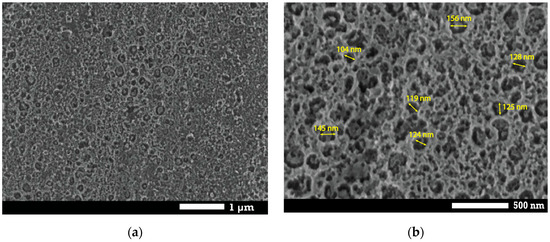
The SEM micrographs depicted on Figure 1 clearly reveal the porous morphology of the anodized a-TiO2 substrate, featuring a uniform dispersion of pores. In more detail, the pores are evenly distributed across the surface, with diameters ranging from 100 to 150 nm, forming a uniform porous layer with open channels.
Figure 1.
Top-view SEM images of the as-prepared anodized a-TiO2 substrate at (a) ×20 k and (b) ×50 k magnification.
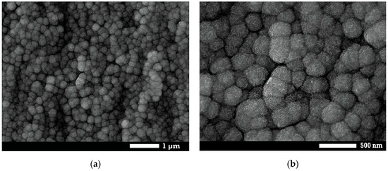
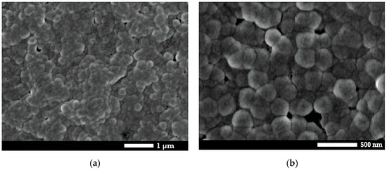
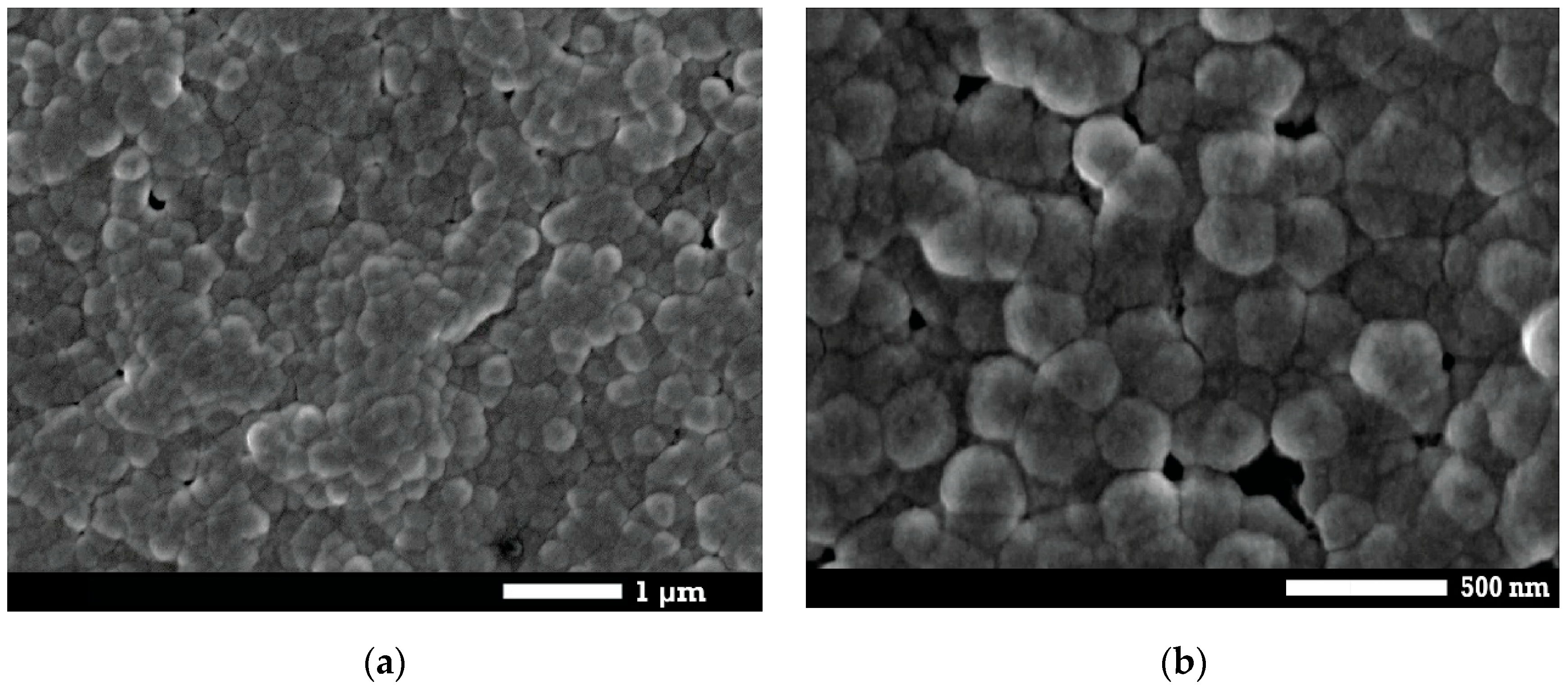
Upon electrodeposition of Ni on the a-TiO2 substrate with a charge density equal to 1463 mC cm−2, a uniform, nodular overlayer of Ni nanoparticles was observed, with an average size of ca. 250 nm (Figure 2). No large agglomerates were detected, indicating a homogeneous deposit. This qNi value was selected as it corresponded to the deposition condition that yielded the best electrocatalytic activity (see later). As can be seen in Figure 3, after galvanic replacement, the overall granular morphology was preserved, and the particle size remained essentially unchanged, indicating rapid formation of an Ir skin (see EDS analysis below). A subtle change that can be inferred includes some further particle coalescence/denser packing, in line too with the formation of an Ir surface layer over largely intact Ni particles. Upon sample anodization to form IrOx the particles coalesce (indicating volume expansion upon Ir transformation to IrOx) forming a continuous surface.
Figure 2.
Top-view FESEM micrographs of Ni/a-TiO2 (qNi = 1463 mC cm−2) at (a) ×20 k and (b) ×50 k magnification.
Figure 3.
Top-view SEM micrographs of IrOx/Ir-Ni/a-TiO2 (qNi = 1463 mC cm−2) at (a) ×20 k and (b) ×50 k magnification.
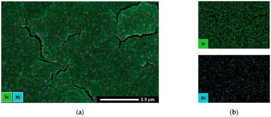
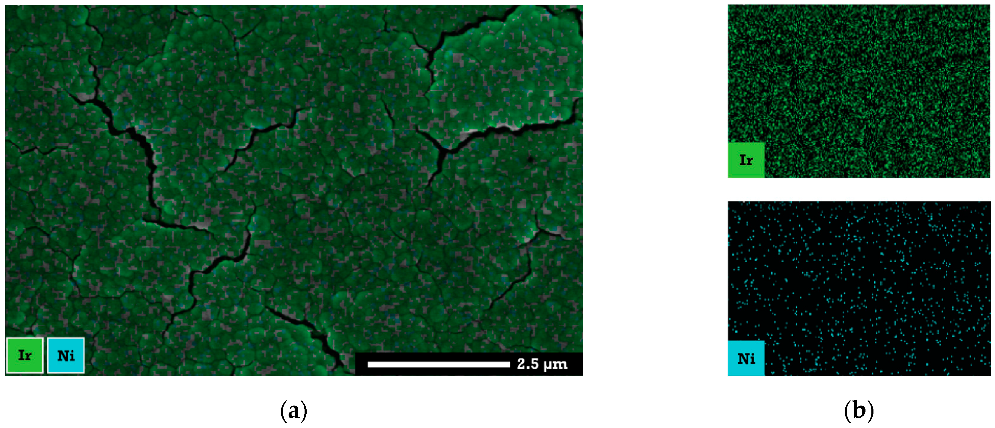
The EDS mapping (Figure 4) clearly reveals a uniform and continuous distribution of Ir across the top layer, with Ir present at a much higher intensity than Ni. This is in good agreement with EDS analysis, which showed an Ir:Ni atomic ratio of ca. 7 and a mass ratio of ca. 18 of the outer deposit. In contrast, bulk composition analysis by ICP-MS revealed a much lower Ir:Ni mass ratio of ca. 0.15, corresponding to an Ir and Ni loading equal to 2.15 μg cm−2 and 14.3 μg cm−2, respectively. This indicates Ir surface segregation as expected for the galvanic replacement preparation method. XPS sputter-etch studies of similar IrO2/Ir/Ni systems by our group have confirmed an IrO2 and NiOx outer shell, a metallic Ir and Ni core [36,38].
Figure 4.
EDS mapping of IrOx/Ir-Ni/a-TiO2 (qNi = 1463 mC cm−2). (a) SEM image with overlaid Ni and Ir signals, (b) Ir and Ni distribution.
3.2. Electrochemical Characterization
3.2.1. Surface Electrochemistry of the Catalysts
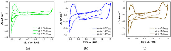
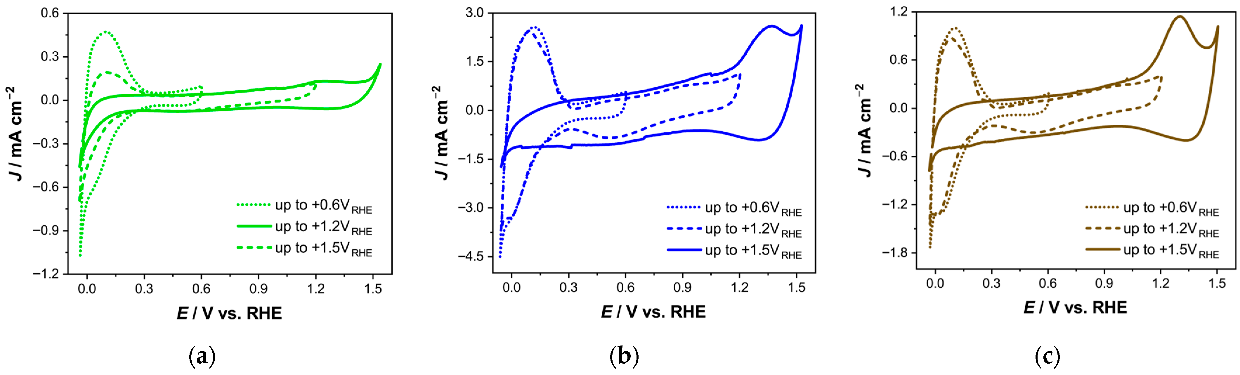
The surface electrochemistry of the IrOx/Ir-Ni/a-TiO2 electrodes was investigated by cyclic voltammetry in a deaerated 0.1 M HClO4 electrolyte, over progressively extended potential windows. Three different Ni deposition charge densities (qNi = 731, 1463 and 2925 mC cm−2) were examined to evaluate the effect of Ni loading. As can be seen in Figure 5, all electrodes displayed characteristic Ir redox features across the entire potential range, including hydrogen underpotential deposition (HUPD) peaks at low potential (ca. +0.1 VRHE) [53,54] and the progressive development of Ir oxide-related redox peaks (ca. +1.4 VRHE) with concurrent HUPD peak suppression, as the upper potential limit is increased [55], confirming successful galvanic replacement of Ni by Ir and its subsequent oxidation to IrOx.
Figure 5.
Cyclic voltammograms of IrOx/Ir-Ni/a-TiO2 electrodes, prepared with different Ni loadings equal to: (a) 731, (b) 1463, and (c) 2926 mC cm−2, recorded in deaerated 0.1 M HClO4 with a scan rate of 50 mV s−1.
The anodic HUPD charge (qHUPD) was integrated to estimate the electrochemically active surface area (ECSA) of metallic Ir prior to IrOx formation, assuming 0.65 of 210 μC cm−2 which corresponds to the adsorption of a hydrogen monolayer on Pt [54]. Similarly, the charge attributed to Ir anodic growth (qIrOx) was determined by integrating the corresponding anodic peak, representing the active IrOx surface [38]. These parameters are summarized in Table 1 for all samples.
Table 1.
Summary of electrochemical parameters for IrOx/Ir-Ni/a-TiO2 electrodes prepared with different Ni loadings.
Among the three electrodes, the most pronounced voltammetric features attributed to Ir were observed for the intermediate Ni loading (qNi = 1463 mC cm−2), which exhibited the highest intensities for both HUPD and IrOx-related peaks. Electrodes with lower (731 mC cm−2) or higher (2926 mC cm−2) charge densities of electrodeposited Ni showed reduced peak intensities, reflecting a reduced Ir surface area.
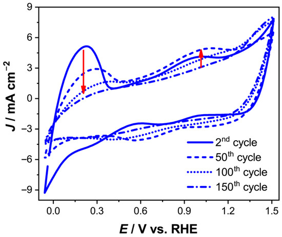
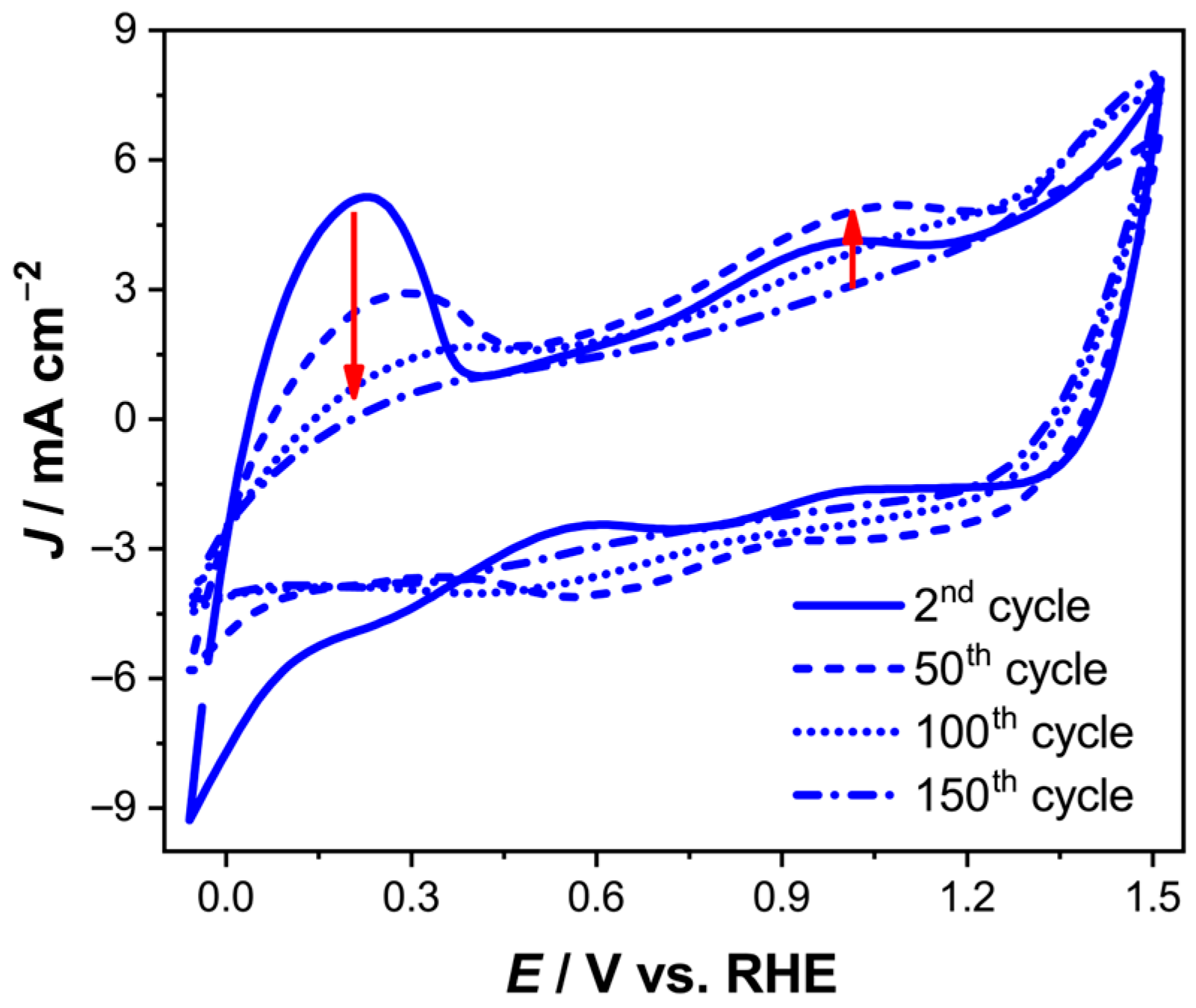
In Figure 6 the evolution of the surface electrochemistry for the IrOx/Ir-Ni/a-TiO2 (qNi = 1463 mC cm−2) electrode is depicted, during repeated cycling with a scan rate of 200 mV s−1. In the initial scans, well-defined Ir redox peaks appear at ca. +0.9 VRHE, corresponding to the reversible Ir(III) ⇌ Ir(IV) transition [50], and their current density increases until a maximum is reached. With continued cycling (~50 cycles), these peaks gradually become less defined and eventually disappear, while a new feature emerges at ca. +1.4 VRHE after ~150 cycles. This shoulder, attributed to the formation of higher-valent IrOx species (Ir(IV/V)) [50,56], appears less distinct at high scan rate but is more clearly resolved in the lower scan rate CVs of Figure 5. In parallel, the progressive suppression of the HUPD peaks confirms the complete conversion of metallic Ir accessible to the electrolyte to porous 3D-IrOx [52,55] (the voltammetric picture remained largely unchanged following the study of OER as described below, as shown in Figure S1 of the Supplementary Materials).
Figure 6.
Cyclic voltammograms of IrOx/Ir-Ni/a-TiO2 (qNi = 1463 mC cm−2) recorded in deaerated 0.1 M HClO4 with a scan rate of 200 mV s−1. Red arrows highlight the evolution of IrOx redox peaks and the attenuation of HUPD features with increasing cycle number.
3.2.2. Oxygen Evolution Reaction
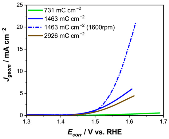
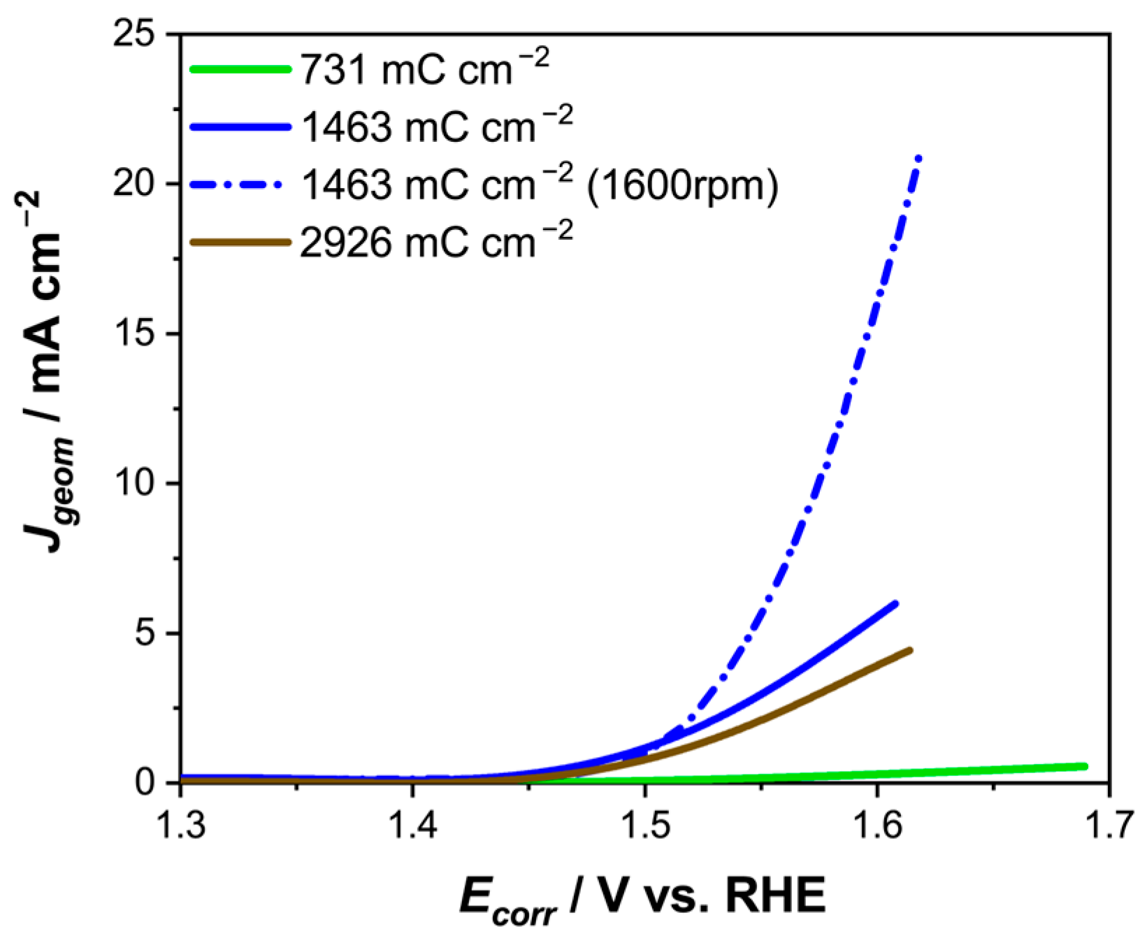
The electrocatalytic activity of the fabricated electrodes toward the OER was evaluated by linear sweep voltammetry under quasi-steady-state conditions. Currents were corrected (post-run) for iR drop by the current-interrupt technique. The application of periodic current-interrupt during LSV (applied at 100 mV intervals during potential scan) also helped to ensure O2 bubble detachment during the current-interrupt step from the electrode’s surface. The resulting iR-corrected curves (post-run) are presented in Figure 7, comparing a-TiO2 supported electrodes prepared with different qNi values.
Figure 7.
Polarization curves of IrOx/Ir-Ni/a-TiO2 electrodes with different Ni loadings (qNi = 731, 1463, and 2926 mC cm−2) obtained using the current-interrupt method in 0.1 M HClO4 deaerated electrolyte with a scan rate of 5 mV s−1. The currents are normalized to the electrodes’ geometric area. The electrode with qNi = 1463 mC cm−2 was also studied under rotation at 1600 rpm.
The sample with qNi = 731 mC cm−2 showed inferior electrocatalytic activity, with the lowest current densities recorded across the investigated potential range. In contrast, both 1463 and 2926 mC cm−2 loadings resulted in substantially enhanced OER performance. Between these, the activity of the two electrodes was comparable, suggesting that beyond a certain threshold of electrodeposited Ni (~1463 mC cm−2), further increase in Ni loading does not significantly improve Ir deposition or catalytic activity. For further evaluation, the electrode with qNi = 1463 mC cm−2 was selected, as it combined enhanced Ir surface electrochemistry with a lower Ni loading, to be studied under rotation at 1600 rpm. This enabled controlled enhanced mass transfer ensuring increased and reproducible bubble detachment from the surface, minimizing electrode clogging and resulting in significantly higher current densities at a given overpotential. The corresponding polarization curves obtained under linear sweep voltammetry, which highlight the mass-transport limitations observed under static conditions and without the O2 bubble release during periodic current-interrupt, are provided in the Supporting Information (Figure S2).
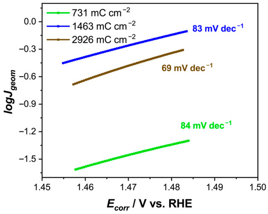
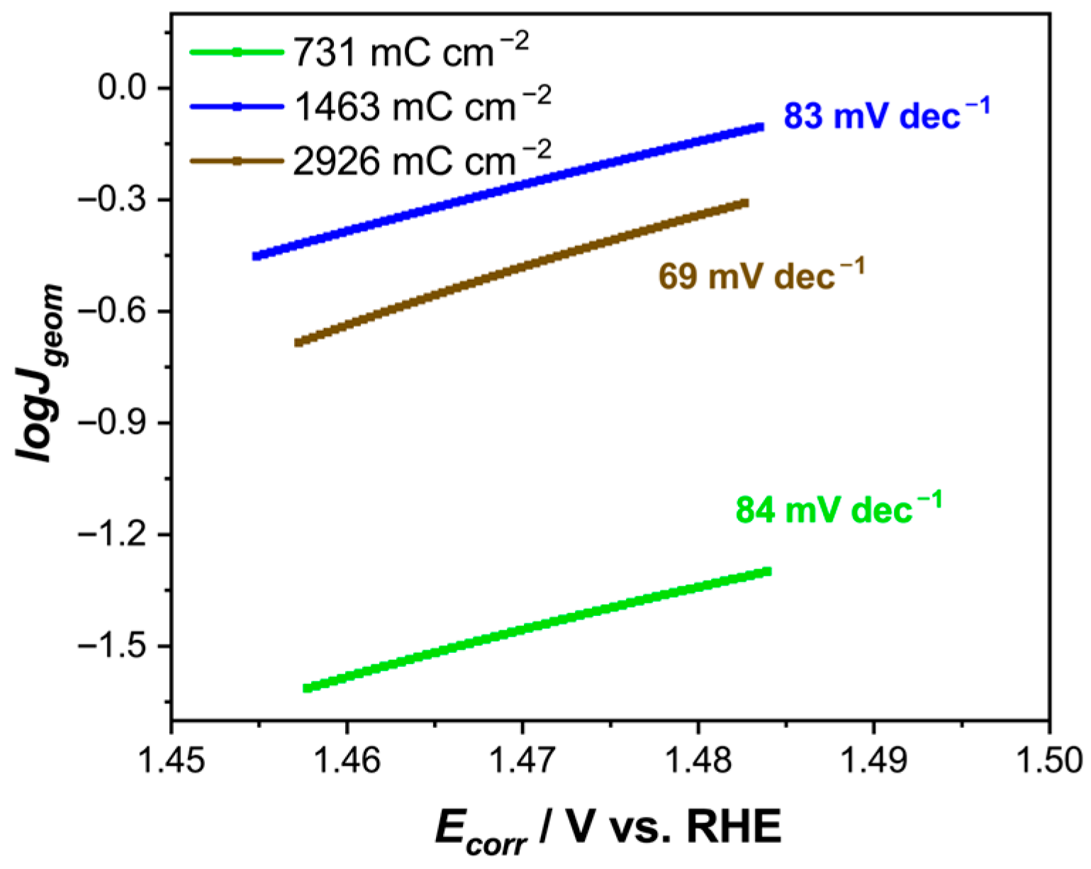
The Tafel slopes calculated from the polarization curves of Figure 7 were equal to 84, 83, and 69 mV dec−1 for the electrodes with Ni loadings of 731, 1463, and 2926 mC cm−2, respectively (Figure 8). These values are relatively close, indicating that all three electrodes follow a similar OER mechanism. The slight deviation from the value of 60 mV dec−1, typically reported for pure IrO2 electrodes [57], may be attributed to factors such as partial mass transfer control and uncorrected ohmic losses.
Figure 8.
Tafel plots for IrOx/Ir-Ni/a-TiO2 electrodes prepared with different Ni loadings in 0.1 M HClO4.
3.2.3. Stability Testing
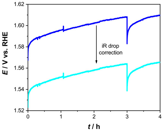
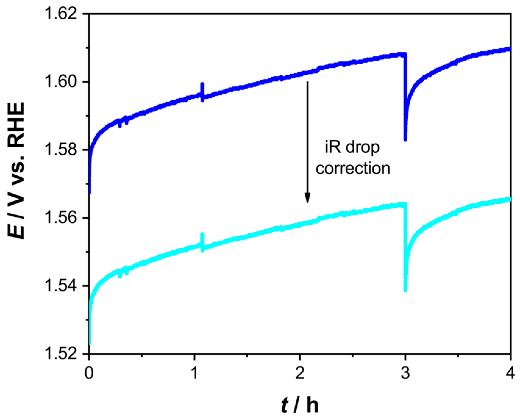
The short-term stability of the best-performing electrode, IrOx/Ir-Ni/a-TiO2 with qNi = 1463 mC cm−2, was evaluated by chronopotentiometry at a current density equal to +5.5 mA cm−2 for 4 h under static conditions. Ohmic drop correction for intense O2 bubble generation was carried out throughout the experiment by applying the current-interrupt technique every hour. The brief potential drop observed coincides with the application of the current-interrupt technique that momentarily disrupts the steady-state current and may facilitate the detachment of accumulated oxygen bubbles from the electrode surface, temporarily improving the local mass transport and decreasing the apparent overpotential. As can be seen in Figure 9, the corrected potential initially recorded at ca. +1.54 VRHE (η ≈ 313 mV) increased slightly to ca. +1.56 VRHE (η ≈ 333 mV) corresponding to a change of only ca. 20 mV over the duration of the experiment. These results indicate that the electrode remained stable during the measurement, with only a minor increase in the overpotential.
Figure 9.
Chronopotentiometric measurement of the IrOx/Ir-Ni/a-TiO2 electrode (qNi = 1463 mC cm−2) at a constant current density of +5.5 mA cm−2 for 4 h in 0.1 M HClO4 under static conditions. The dark blue line corresponds to the uncorrected potential, while the light blue line represents the iR-corrected potential obtained using the current-interrupt method.
4. Discussion
4.1. Catalytic Electrode Morphology
The SEM micrographs at different stages of the fabrication process of the IrOx/Ir-Ni/a-TiO2 (qNi = 1463 mC cm−2) electrode provide valuable information about how the electrode structure evolves. The uniform porous a-TiO2 substrate (Figure 1) promotes electrolyte penetration and creates pathways for Ni to deposit throughout the structure [45]. Upon electrodeposition, Ni finally forms a uniform nodular layer over the porous substrate surface (Figure 2), attributed to the pulsed electrodeposition method applied, which promoted homogeneous nucleation and growth of Ni nanoparticles [58]. Following the galvanic replacement step, the granular appearance and particle size remain essentially unchanged (Figure 3), showing that Ir deposition formed a conformal layer rather than altering the underlying Ni features. Collectively, the surface-sensitive EDS (Figure 4) and bulk ICP-MS analysis paint a consistent picture: the top layer is strongly enriched in Ir relative to Ni, while the bulk composition is Ni-dominated, indicating that most Ni is retained within the porous titania matrix, effectively serving as a current collector (otherwise, no electrochemistry would have been recorded), whereas Ir resides predominantly at the outer surface.
Indeed, the distinct HUPD and Ir(III)/Ir(IV) peaks observed for all electrodes across the investigated potential range (Figure 5 and Figure 6) confirm that Ni is not limited to the surface but instead provides electronic continuity throughout the structure, enabling full electrochemical accessibility of the surface Ir. This distribution is attributed to the defect-rich amorphous oxide and the brief negative polarization/cathodization step [29], which allowed for the formation of Ti3+ states at the metal/oxide interface. As a result, a conductivity gradient is established and becomes the driving force for the deposition to begin at internal sites of the porous matrix [48]. This arrangement, with Ir concentrated at the top surface and Ni embedded within the pores, is advantageous as it maximizes Ir utilization while maintaining efficient electron transport through the underlying Ni network.
4.2. Catalytic Electrode Performance—Effect of Ni Loading
Having established that a-TiO2 supports the formation of an electrochemically active IrOx layer, we next consider how the amount of electrodeposited Ni (qNi) influences the catalyst structure and activity. Cyclic voltammetry revealed the most pronounced Ir-related features for the intermediate loading (1463 mC cm−2), suggesting that a greater portion of the deposited Ir was electrochemically accessible and effectively converted to IrOx [52], while weaker responses were recorded for both lower and higher qNi (Figure 5).
This trend in the surface electrochemistry is consistent with the OER performance of the electrodes (Figure 7). The intermediate Ni loading (1463 mC cm−2) achieved the highest catalytic activity, in line with its well-defined Ir-related redox peaks. In comparison, the 2926 mC cm−2 electrode showed slightly lower activity, reflecting its less intense redox signals compared to the intermediate sample. This suggests that once a sufficient amount of Ni is deposited to establish good electronic conductivity up to the surface of titania pores, further increasing the Ni loading does not enhance the electrocatalytic performance, since in that case a continuous Ni overlayer is formed resulting in a continuous Ir layer of lower surface area. Meanwhile, the 731 mC cm−2 sample, with minimal IrOx signals, showed the poorest activity.
The optimized electrode (qNi = 1463 mC cm−2) also demonstrated good short-term stability, with only a minor potential increase of 20 mV over 4 h of continuous operation at 5.5 mA cm−2. While long-term studies are needed for a full durability assessment, these results indicate that the catalyst remains relatively stable under OER conditions.
Finally, the mass-specific electrocatalytic activity of the IrOx/Ir-Ni/a-TiO2 (qNi=1453 mC cm−2) electrode is competitive with similar Ir-Ni catalysts reported in the literature (Table 2). While several studies report similar overpotentials at 10 mA cm−2, these values are typically achieved at much higher Ir loadings, often an order of magnitude greater than in this work. In contrast, our electrode delivers notable OER activity with an ultra-low Ir loading of only 2.15 μgIr cm−2, showing that the combination of this fabrication strategy and amorphous TiO2 as a substrate effectively maximizes Ir utilization and offers a promising pathway toward cost-efficient, high-performance OER electrocatalysts.
Table 2.
Comparison of overpotential, mass activity, and Ir loading for various Ir-Ni based OER catalysts, all measured in room temperature.
5. Conclusions
- 1.
- Investigation of different qNi values on a-TiO2 revealed that tuning the Ni loading toward an intermediate value yields the highest OER activity, since it provides an optimal Ni dispersion up to the mouth of titania pore, ensuring both electronic connectivity with the bottom of the substrate and the optimum Ir dispersion on the exposed to the solution Ni surface. Low Ni loading led to incomplete pore filling and limited Ir deposition within the pores, while increasing the loading beyond a certain value did not result in further improvements in electrocatalytic performance.
- 2.
- The complementary use of SEM/EDS and ICP-MS for the IrOx/Ir-Ni/a-TiO2 (qNi = 1463 mC cm−2) electrode confirmed a surface-enriched, uniform Ir film on Ni/a-TiO2, indicating that Ni remained predominantly embedded within the porous layer, consistent with its role as a current collector.
- 3.
- The optimized IrOx/Ir-Ni/a-TiO2 electrode exhibits a mass activity of 1.68 A mgIr−1 at an overpotential of 300 mV, comparable to or exceeding similar catalysts reported in the literature, while operating with an ultra-low Ir loading of 2.15 μgIr cm−2, demonstrating the effectiveness of both the fabrication strategy and the amorphous TiO2 substrate for the development of cost-efficient, high-performance OER electrodes.
Supplementary Materials
The following supporting information can be downloaded at: https://www.mdpi.com/article/10.3390/suschem7010002/s1, Figure S1: Cyclic voltammograms of IrOx/Ir-Ni/a-TiO2 electrode with qNi = 1463 mC cm−2, recorded in deaerated 0.1 M HClO4 with a scan rate of 50 mV s−1, before and after testing for the OER; Figure S2: iR-drop corrected LSV curves obtained at 5 mV s−1 in 0.1 M HClO4 deaerated electrolyte with and without the implementation of the current-interrupt technique at 100 mV intervals for the sample with qNi=1463 mC cm−2; Figure S3: Nyquist plot obtained from electrochemical impedance spectroscopy of an IrOx/Ir-Ni/a-TiO2 electrode (qNi = 1463 mC cm−2) at potential of +1.5VRHE, together with the fit to the equivalent electrical circuit Rs(RfQf)(RctQdl). The inset shows the equivalent electrical circuit; Figure S4: Comparison of Tafel slopes obtained for an IrOx/Ir-Ni/a-TiO2 electrode (prepared under identical conditions to the 1463 mC cm−2 sample) using two different procedures for determining the solution resistance (Rs): (i) the current-interrupt method and (ii) electrochemical impedance spectroscopy (EIS); Table S1: Parameters of the equivalent circuit shown in Figure S3 at the applied potential value of +1.50 VRHE for the IrOx/Ir-Ni/a-TiO2 electrode (qNi = 1463 mC cm−2) electrode. Reference [64] are cited in the Supplementary Materials.
Author Contributions
Conceptualization, E.M. and S.S.; methodology, E.M. and S.S.; formal analysis, E.M. and S.S.; investigation, E.M., T.K., M.Z., M.N., A.B. and D.A.L.; writing—original draft preparation, E.M.; writing—review and editing, E.M. and S.S.; supervision, S.S.; project administration, S.S.; funding acquisition, S.S. All authors have read and agreed to the published version of the manuscript.
Funding
This project was funded by the European Union HORIZON Research and Innovation Actions under grant agreement ID 101122323.
Data Availability Statement
The original data presented in this study are openly available in Zenodo at https://doi.org/10.5281/zenodo.17879879.
Conflicts of Interest
The authors declare no conflicts of interest.
Abbreviations
The following abbreviations are used in this manuscript:
| OER | Oxygen Evolution Reaction |
| DSAs | Dimensionally Stable Anodes |
| CVD | Chemical Vapor Deposition |
| PGM | Platinum-Group Metal |
| GC | Glassy Carbon |
| SCE | Saturated Calomel Electrode |
| CV | Cyclic Voltammetry |
| LSV | Linear Sweep Voltammetry |
| RDE | Rotating Disk Electrode |
| RHE | Reversible Hydrogen Electrode |
| SEM | Scanning Electron Microscopy |
| EDS | Energy Dispersive X-ray Spectroscopy |
| FESEM | Field Emission Scanning Electron Microscopy |
| ICP-MS | Inductively Coupled Plasma Mass Spectrometry |
| ECSA | Electrochemically Active Surface Area |
| ATO | Antimony-doped Tin Oxide |
References
- Trębala, M.; Łamacz, A. Modern Catalytic Materials for the Oxygen Evolution Reaction. Molecules 2025, 30, 1656. [Google Scholar] [CrossRef] [Scilit]
- Li, W.; Tian, H.; Ma, L.; Wang, Y.; Liu, X.; Gao, X. Low-Temperature Water Electrolysis: Fundamentals, Progress, and New Strategies. Mater. Adv. 2022, 3, 5598–5644. [Google Scholar] [CrossRef] [Scilit]
- Che, K.; Zhu, X.; Tang, G.; Zhao, M.; Pan, J. In Situ Electroplating of Ir@Carbon Cloth as High-Performance Selective Oxygen Evolution Reaction Catalyst for Direct Electrolytic Recovery of Lead. Catalysts 2023, 13, 322. [Google Scholar] [CrossRef] [Scilit]
- Feng, Y.; Yang, L.; Liu, J.; Logan, B.E. Electrochemical Technologies for Wastewater Treatment and Resource Reclamation. Environ. Sci. 2016, 2, 800–831. [Google Scholar] [CrossRef] [Scilit]
- Couper, A.M.; Pletcher, D.; Walsh, F.C. Electrode Materials for Electrosynthesis. Chem. Rev. 1990, 90, 837–865. [Google Scholar] [CrossRef] [Scilit]
- Suen, N.T.; Hung, S.F.; Quan, Q.; Zhang, N.; Xu, Y.J.; Chen, H.M. Electrocatalysis for the Oxygen Evolution Reaction: Recent Development and Future Perspectives. Chem. Soc. Rev. 2017, 46, 337–365. [Google Scholar] [CrossRef] [Scilit]
- Bo, G.; Li, P.; Fan, Y.; Zheng, X.; Zhao, M.; Zhu, Q.; Fu, Y.; Li, Y.; Pang, W.K.; Lai, W.H.; et al. 2D Ferromagnetic M3GeTe2 (M = Ni/Fe) for Boosting Intermediates Adsorption toward Faster Water Oxidation. Adv. Sci. 2024, 11, e2310115. [Google Scholar] [CrossRef] [Scilit]
- Han, Y.; Wang, J.; Liu, Y.; Li, T.; Wang, T.; Li, X.; Ye, X.; Li, G.; Li, J.; Hu, W.; et al. Stability Challenges and Opportunities of NiFe-Based Electrocatalysts for Oxygen Evolution Reaction in Alkaline Media. Carbon Neutralization 2024, 3, 172–198. [Google Scholar] [CrossRef] [Scilit]
- Trasatti, S. Electrocatalysis: Understanding the Success of DSA®. Electrochim. Acta 2000, 45, 2377–2385. [Google Scholar] [CrossRef] [Scilit]
- Danilovic, N.; Subbaraman, R.; Chang, K.C.; Chang, S.H.; Kang, Y.J.; Snyder, J.; Paulikas, A.P.; Strmcnik, D.; Kim, Y.T.; Myers, D.; et al. Activity-Stability Trends for the Oxygen Evolution Reaction on Monometallic Oxides in Acidic Environments. J. Phys. Chem. Lett. 2014, 5, 2474–2478. [Google Scholar] [CrossRef] [Scilit]
- Uekert, T.; Wikoff, H.M.; Badgett, A. Electrolyzer and Fuel Cell Recycling for a Circular Hydrogen Economy. Adv. Sustain. Syst. 2024, 8, 2300449. [Google Scholar] [CrossRef] [Scilit]
- Takahashi, K.; Sanekata, R.; Nagai, T. Volatile Separation and Recovery of Iridium from Oxygen Evolution Electrodes Using Calcium Oxide. Mater. Trans. 2024, 65, 71–75. [Google Scholar] [CrossRef] [Scilit]
- Minke, C.; Suermann, M.; Bensmann, B.; Hanke-Rauschenbach, R. Is Iridium Demand a Potential Bottleneck in the Realization of Large-Scale PEM Water Electrolysis? Int. J. Hydrogen Energy 2021, 46, 23581–23590. [Google Scholar] [CrossRef] [Scilit]
- Abbott, D.F.; Lebedev, D.; Waltar, K.; Povia, M.; Nachtegaal, M.; Fabbri, E.; Copéret, C.; Schmidt, T.J. Iridium Oxide for the Oxygen Evolution Reaction: Correlation between Particle Size, Morphology, and the Surface Hydroxo Layer from Operando XAS. Chem. Mater. 2016, 28, 6591–6604. [Google Scholar] [CrossRef] [Scilit]
- Slavcheva, E.; Radev, I.; Bliznakov, S.; Topalov, G.; Andreev, P.; Budevski, E. Sputtered Iridium Oxide Films as Electrocatalysts for Water Splitting via PEM Electrolysis. Electrochim. Acta 2007, 52, 3889–3894. [Google Scholar] [CrossRef] [Scilit]
- Kariman, A.; Marshall, A.T. Improving the Stability of DSA Electrodes by the Addition of TiO2 Nanoparticles. J. Electrochem. Soc. 2019, 166, E248–E251. [Google Scholar] [CrossRef] [Scilit]
- Böhm, D.; Beetz, M.; Gebauer, C.; Bernt, M.; Schröter, J.; Kornherr, M.; Zoller, F.; Bein, T.; Fattakhova-Rohlfing, D. Highly Conductive Titania Supported Iridium Oxide Nanoparticles with Low Overall Iridium Density as OER Catalyst for Large-Scale PEM Electrolysis. Appl. Mater. Today 2021, 24, 101134. [Google Scholar] [CrossRef] [Scilit]
- Tran, H.P.; Nong, H.N.; Zlatar, M.; Yoon, A.; Hejral, U.; Rüscher, M.; Timoshenko, J.; Selve, S.; Berger, D.; Kroschel, M.; et al. Reactivity and Stability of Reduced Ir-Weight TiO2-Supported Oxygen Evolution Catalysts for Proton Exchange Membrane (PEM) Water Electrolyzer Anodes. J. Am. Chem. Soc. 2024, 146, 31444–31455. [Google Scholar] [CrossRef] [Scilit]
- Chen, K.; Shen, T.; Lu, Y.; Hu, Y.; Wang, J.; Zhang, J.; Wang, D. Engineering Titanium Oxide-Based Support for Electrocatalysis. J. Energy Chem. 2022, 67, 168–183. [Google Scholar] [CrossRef] [Scilit]
- Su, T.; Yang, Y.; Na, Y.; Fan, R.; Li, L.; Wei, L.; Yang, B.; Cao, W. An Insight into the Role of Oxygen Vacancy in Hydrogenated TiO2 Nanocrystals in the Performance of Dye-Sensitized Solar Cells. ACS Appl. Mater. Interfaces 2015, 7, 3754–3763. [Google Scholar] [CrossRef] [Scilit]
- Li, H.; Chen, Z.; Tsang, C.K.; Li, Z.; Ran, X.; Lee, C.; Nie, B.; Zheng, L.; Hung, T.; Lu, J.; et al. Electrochemical Doping of Anatase TiO2 in Organic Electrolytes for High-Performance Supercapacitors and Photocatalysts. J. Mater. Chem. A Mater. 2014, 2, 229–236. [Google Scholar] [CrossRef] [Scilit]
- Andronic, L.; Enesca, A. Black TiO2 Synthesis by Chemical Reduction Methods for Photocatalysis Applications. Front. Chem. 2020, 8, 565489. [Google Scholar] [CrossRef] [Scilit] [PubMed]
- Lü, X.; Yang, W.; Quan, Z.; Lin, T.; Bai, L.; Wang, L.; Huang, F.; Zhao, Y. Enhanced Electron Transport in Nb-Doped TiO2 Nanoparticles via Pressure-Induced Phase Transitions. J. Am. Chem. Soc. 2014, 136, 419–426. [Google Scholar] [CrossRef] [Scilit] [PubMed]
- Bele, M.; Jovanovič, P.; Marinko, Ž.; Drev, S.; Šelih, V.S.; Kovač, J.; Gaberšček, M.; Koderman Podboršek, G.; Dražić, G.; Hodnik, N.; et al. Increasing the Oxygen-Evolution Reaction Performance of Nanotubular Titanium Oxynitride-Supported Ir Nanoparticles by a Strong Metal-Support Interaction. ACS Catal. 2020, 10, 13688–13700. [Google Scholar] [CrossRef] [Scilit]
- Regmi, Y.N.; Tzanetopoulos, E.; Zeng, G.; Peng, X.; Kushner, D.I.; Kistler, T.A.; King, L.A.; Danilovic, N. Supported Oxygen Evolution Catalysts by Design: Toward Lower Precious Metal Loading and Improved Conductivity in Proton Exchange Membrane Water Electrolyzers. ACS Catal. 2020, 10, 13125–13135. [Google Scholar] [CrossRef] [Scilit]
- Zhang, J.; Bang, J.H.; Tang, C.; Kamat, P.V. Tailored TiO2-SrTiO3 Heterostructure Nanotube Arrays for Improved Photoelectrochemical Performance. ACS Nano 2010, 4, 387–395. [Google Scholar] [CrossRef] [Scilit]
- Kontos, A.I.; Likodimos, V.; Stergiopoulos, T.; Tsoukleris, D.S.; Falaras, P.; Rabias, I.; Papavassiliou, G.; Kim, D.; Kunze, J.; Schmuki, P. Self-Organized Anodic TiO2 Nanotube Arrays Functionalized by Iron Oxide Nanoparticles. Chem. Mater. 2009, 21, 662–672. [Google Scholar] [CrossRef] [Scilit]
- Mawlong, L.P.L.; Paul, K.K.; Giri, P.K. Direct Chemical Vapor Deposition Growth of Monolayer MoS2 on TiO2 Nanorods and Evidence for Doping-Induced Strong Photoluminescence Enhancement. J. Phys. Chem. C 2018, 122, 15017–15025. [Google Scholar] [CrossRef] [Scilit]
- Macak, J.M.; Gong, B.G.; Hueppe, M.; Schmuki, P. Filling of TiO2 Nanotubes by Self-Doping and Electrodeposition. Adv. Mater. 2007, 19, 3027–3031. [Google Scholar] [CrossRef] [Scilit]
- Mohanty, U.S. Electrodeposition: A Versatile and Inexpensive Tool for the Synthesis of Nanoparticles, Nanorods, Nanowires, and Nanoclusters of Metals. J. Appl. Electrochem. 2011, 41, 257–270. [Google Scholar] [CrossRef] [Scilit]
- Inamuddin; Boddula, R.; Asiri, A.M. (Eds.) Methods for Electrocatalysis; Springer International Publishing: Cham, Switzerland, 2020; ISBN 978-3-030-27160-2. [Google Scholar]
- Kim, J.; Kim, H.; Han, G.H.; Hong, S.; Park, J.; Bang, J.; Kim, S.Y.; Ahn, S.H. Electrodeposition: An Efficient Method to Fabricate Self—supported Electrodes for Electrochemical Energy Conversion Systems. Exploration 2022, 2, 20210077. [Google Scholar] [CrossRef] [Scilit] [PubMed]
- Kong, X.; Wu, H.; Lu, K.; Zhang, X.; Zhu, Y.; Lei, H. Galvanic Replacement Reaction: Enabling the Creation of Active Catalytic Structures. ACS Appl. Mater. Interfaces 2023, 15, 41205–41223. [Google Scholar] [CrossRef] [Scilit] [PubMed]
- Papaderakis, A.; Mintsouli, I.; Georgieva, J.; Sotiropoulos, S. Electrocatalysts Prepared by Galvanic Replacement. Catalysts 2017, 7, 80. [Google Scholar] [CrossRef] [Scilit]
- Papaderakis, A.; Matouli, I.; Spyridou, O.N.; Grammenos, A.O.; Banti, A.; Touni, A.; Pliatsikas, N.; Patsalas, P.; Sotiropoulos, S. Ternary IrO2-Pt-Ni Deposits Prepared by Galvanic Replacement as Bifunctional Oxygen Catalysts. J. Electroanal. Chem. 2020, 877, 114499. [Google Scholar] [CrossRef] [Scilit]
- Papaderakis, A.; Pliatsikas, N.; Prochaska, C.; Vourlias, G.; Patsalas, P.; Tsiplakides, D.; Balomenou, S.; Sotiropoulos, S. Oxygen Evolution at IrO2 Shell-Ir-Ni Core Electrodes Prepared by Galvanic Replacement. J. Phys. Chem. C 2016, 120, 19995–20005. [Google Scholar] [CrossRef] [Scilit]
- Holde, F.B.; Sebastián-Pascual, P.; Dalby, K.N.; Gómez, E.; Escudero-Escribano, M. Nanostructured Ir-Based Electrocatalysts for Oxygen Evolution Prepared by Galvanic Displacement of Co and Ni. Electrochim. Acta 2023, 467, 143058. [Google Scholar] [CrossRef] [Scilit]
- Touni, A.; Papaderakis, A.; Karfaridis, D.; Vourlias, G.; Sotiropoulos, S. Oxygen Evolution Reaction at IrO2/Ir(Ni) Film Electrodes Prepared by Galvanic Replacement and Anodization: Effect of Precursor Ni Film Thickness. Molecules 2019, 24, 2095. [Google Scholar] [CrossRef] [Scilit]
- Kim, S.; Jeong, J.; Kwon, Y. Nickel Core-Iridium Oxide Shell Catalysts Prepared by Galvanic Replacement Method for Enhancing Oxygen Evolution Reaction in Proton Exchange Membrane Water Electrolysis. Int. J. Hydrogen Energy 2025, 119, 231–238. [Google Scholar] [CrossRef] [Scilit]
- Pi, Y.; Shao, Q.; Wang, P.; Guo, J.; Huang, X. General Formation of Monodisperse IrM (M = Ni, Co, Fe) Bimetallic Nanoclusters as Bifunctional Electrocatalysts for Acidic Overall Water Splitting. Adv. Funct. Mater. 2017, 27, 1700886. [Google Scholar] [CrossRef] [Scilit]
- Strickler, A.L.; Flores, R.A.; King, L.A.; Nørskov, J.K.; Bajdich, M.; Jaramillo, T.F. Systematic Investigation of Iridium-Based Bimetallic Thin Film Catalysts for the Oxygen Evolution Reaction in Acidic Media. ACS Appl. Mater. Interfaces 2019, 11, 34059–34066. [Google Scholar] [CrossRef] [Scilit]
- Zhang, N.; Wang, Y.; Wu, R.; Yang, X.; Wu, Y.; Wang, F.; Cui, P.; Liu, G.; Jiang, W.; Xie, H. NiIr Nanowire Assembles as an Efficient Electrocatalyst Towards Oxygen Evolution Reaction in Both Acid and Alkaline Media. Chem. Asian J. 2025, 20, e202400851. [Google Scholar] [CrossRef] [Scilit] [PubMed]
- Touni, A.; Grammenos, O.A.; Banti, A.; Karfaridis, D.; Prochaska, C.; Lambropoulou, D.; Pavlidou, E.; Sotiropoulos, S. Iridium Oxide-Nickel-Coated Titanium Anodes for the Oxygen Evolution Reaction. Electrochim. Acta 2021, 390, 138866. [Google Scholar] [CrossRef] [Scilit]
- Yan, S.; Zhong, M.; Zhu, W.; Li, W.; Chen, X.; Li, M.; Wang, C.; Lu, X. Controllable Fabrication of a Nickel-Iridium Alloy Network by Galvanic Replacement Engineering for High-Efficiency Electrocatalytic Water Splitting. Inorg. Chem. Front. 2022, 9, 6225–6236. [Google Scholar] [CrossRef] [Scilit]
- Touni, A.; Mitrousi, E.; Carvalho, P.; Nikopoulou, M.; Pavlidou, E.; Lambropoulou, D.A.; Sotiropoulos, S. IrO2-Decorated Titania Nanotubes as Oxygen Evolution Anodes. Molecules 2025, 30, 2921. [Google Scholar] [CrossRef] [Scilit]
- Fabbri, E.; Habereder, A.; Waltar, K.; Kötz, R.; Schmidt, T.J. Developments and Perspectives of Oxide-Based Catalysts for the Oxygen Evolution Reaction. Catal. Sci. Technol. 2014, 4, 3800–3821. [Google Scholar] [CrossRef] [Scilit]
- Liu, X.; Carvalho, P.; Getz, M.N.; Norby, T.; Chatzitakis, A. Black Anatase TiO2 Nanotubes with Tunable Orientation for High Performance Supercapacitors. J. Phys. Chem. C 2019, 123, 21931–21940. [Google Scholar] [CrossRef] [Scilit]
- Li, Z.; Ding, Y.; Kang, W.; Li, C.; Lin, D.; Wang, X.; Chen, Z.; Wu, M.; Pan, D. Reduction Mechanism and Capacitive Properties of Highly Electrochemically Reduced TiO2 Nanotube Arrays. Electrochim. Acta 2015, 161, 40–47. [Google Scholar] [CrossRef] [Scilit]
- Nielsch, K.; Müller, F.; Li, A.-P.; Gösele, U. Uniform Nickel Deposition into Ordered Alumina Pores by Pulsed Electrodeposition. Adv. Mater. 2000, 12, 582–586. [Google Scholar] [CrossRef]
- Juodkazyte, J.; Šebeka, B.; Valsiunas, I.; Juodkazis, K. Iridium Anodic Oxidation to Ir(III) and Ir(IV) Hydrous Oxides. Electroanalysis 2005, 17, 947–952. [Google Scholar] [CrossRef] [Scilit]
- Esquius, J.R.; Algara-Siller, G.; Spanos, I.; Freakley, S.J.; Schlögl, R.; Hutchings, G.J. Preparation of Solid Solution and Layered Irox−Ni(OH)2 Oxygen Evolution Catalysts: Toward Optimizing Iridium Efficiency for OER. ACS Catal. 2020, 10, 14640–14648. [Google Scholar] [CrossRef] [Scilit]
- Zlatar, M.; Xie, X.; Franke, C.; Hrbek, T.; Krtouš, Z.; Li, T.; Khalakhan, I.; Cherevko, S. On the Growth and Water Oxidation Stability of Hydrous Iridium Oxide. EES Catal. 2025, 3, 521–534. [Google Scholar] [CrossRef] [Scilit]
- Mozota, J.; Conway, B.E. Surface and Bulk Processes at Oxidized Iridium Electrodes—I. Monolayer Stage and Transition to Reversible Multilayer Oxide Film Behaviour. Electrochim. Acta 1983, 28, 1–8. [Google Scholar] [CrossRef] [Scilit]
- Woods, R. Hydrogen Adsorption on Platinum, Iridium and Rhodium Electrodes at Reduced Temperatures and the Determination of Real Surface Area. J. Electroanal. Chem. Interfacial Electrochem. 1974, 49, 217–226. [Google Scholar] [CrossRef]
- Rand, D.A.J.; Woods, R. Cyclic Voltammetric Studies on Iridium Electrodes in Sulphuric Acid Solutions. J. Electroanal. Chem. Interfacial Electrochem. 1974, 55, 375–381. [Google Scholar] [CrossRef]
- Pavlovic, Z.; Ranjan, C.; Gao, Q.; Van Gastel, M.; Schlögl, R. Probing the Structure of a Water-Oxidizing Anodic Iridium Oxide Catalyst Using Raman Spectroscopy. ACS Catal. 2016, 6, 8098–8105. [Google Scholar] [CrossRef] [Scilit]
- Hu, J.M.; Zhang, J.Q.; Cao, C.N. Oxygen Evolution Reaction on IrO2-Based DSA® Type Electrodes: Kinetics Analysis of Tafel Lines and EIS. Int. J. Hydrogen Energy 2004, 29, 791–797. [Google Scholar] [CrossRef] [Scilit]
- Boukhouiete, A.; Boumendjel, S.; Sobhi, N.e.l.H.; Creus, J. Microstructural Investigation of Nickel Deposits Obtained by Pulsed Current. J. Indian Chem. Soc. 2022, 99, 100331. [Google Scholar] [CrossRef] [Scilit]
- Nong, H.N.; Oh, H.S.; Reier, T.; Willinger, E.; Willinger, M.G.; Petkov, V.; Teschner, D.; Strasser, P. Oxide-Supported IrNiOx Core-Shell Particles as Efficient, Cost-Effective, and Stable Catalysts for Electrochemical Water Splitting. Angew. Chem.-Int. Ed. 2015, 54, 2975–2979. [Google Scholar] [CrossRef] [Scilit]
- Reier, T.; Pawolek, Z.; Cherevko, S.; Bruns, M.; Jones, T.; Teschner, D.; Selve, S.; Bergmann, A.; Nong, H.N.; Schlögl, R.; et al. Molecular Insight in Structure and Activity of Highly Efficient, Low-Ir Ir-Ni Oxide Catalysts for Electrochemical Water Splitting (OER). J. Am. Chem. Soc. 2015, 137, 13031–13040. [Google Scholar] [CrossRef] [Scilit]
- Spöri, C.; Briois, P.; Nong, H.N.; Reier, T.; Billard, A.; Kühl, S.; Teschner, D.; Strasser, P. Experimental Activity Descriptors for Iridium-Based Catalysts for the Electrochemical Oxygen Evolution Reaction (OER). ACS Catal. 2019, 9, 6653–6663. [Google Scholar] [CrossRef] [Scilit]
- Tran, H.P.; Nong, H.N.; Oh, H.S.; Klingenhof, M.; Kroschel, M.; Paul, B.; Hübner, J.; Teschner, D.; Strasser, P. Catalyst-Support Surface Charge Effects on Structure and Activity of IrNi-Based Oxygen Evolution Reaction Catalysts Deposited on Tin-Oxide Supports. Chem. Mater. 2022, 34, 9350–9363. [Google Scholar] [CrossRef] [Scilit]
- Esquius, J.R.; LaGrow, A.P.; Jin, H.; Yu, Z.; Araujo, A.; Marques, R.; Mendes, A.; Liu, L. Mixed Iridium-Nickel Oxides Supported on Antimony-Doped Tin Oxide as Highly Efficient and Stable Acidic Oxygen Evolution Catalysts. Mater. Futures 2024, 3, 015102. [Google Scholar] [CrossRef] [Scilit]
- Hsu, C.H.; Mansfeld, F. Technical Note: Concerning the Conversion of the Constant Phase Element Parameter Y 0 into a Capacitance. Corrosion 2001, 57, 747–748. [Google Scholar] [CrossRef] [Scilit]

Disclaimer/Publisher’s Note: The statements, opinions and data contained in all publications are solely those of the individual author(s) and contributor(s) and not of MDPI and/or the editor(s). MDPI and/or the editor(s) disclaim responsibility for any injury to people or property resulting from any ideas, methods, instructions or products referred to in the content. |
© 2026 by the authors. Licensee MDPI, Basel, Switzerland. This article is an open access article distributed under the terms and conditions of the Creative Commons Attribution (CC BY) license.