


Abstract
Low-voltage grids are undergoing rapid change as rooftop photovoltaics, electric vehicles and other distributed energy resources increase their share of demand. Without new local control, these trends risk more frequent voltage problems and costly reinforcement, which can slow affordable and just energy transitions. This article proposes a MATLAB/Simulink methodology for designing and comparing PID and Mamdani fuzzy volt–var controllers implemented at a single PV inverter in a radial low-voltage feeder. The feeder model aggregates residential demand, two PV units, a small wind unit, battery storage and an EV charging event; controller performance is assessed using time-domain simulations and scalar indices of overshoot, undershoot, settling time, time outside a ±5% voltage band, and reactive power usage. In the studied high-PV scenario, both controllers maintain acceptable voltage quality with limited overshoot and short settling times, while the fuzzy controller yields smoother transients at the expense of slightly higher but still modest reactive power adjustments. The results illustrate how accessible digital tools can help system operators and regulators explore local volt–var strategies that increase renewable hosting capacity and power quality compliance without immediate grid reinforcement, thereby supporting sustainable electrification in the context of the fourth industrial revolution.
1. Introduction
Low-voltage (LV) distribution grids are rapidly changing due to increasing penetration of rooftop photovoltaic (PV) units, wind generation, battery storage and electric vehicles (EVs). While regulating reactive power exchange with the upstream grid, these converter-interfaced resources affect power flow patterns and make it more difficult to maintain voltages within legal bounds [1,2]. As a result, reactive power optimization and voltage management have emerged as crucial operational duties. In contemporary grids and consumer facilities, volt–var techniques are acknowledged as efficient ways to lower losses, enhance power factor, and adhere to voltage limits [1,3]. Traditional voltage regulation equipment designed for passive, one-directional power flows—such as on-load tap changers and fixed capacitor banks—often becomes insufficient or suboptimal when LV feeders host large shares of PV generation and EV charging [2,4]. This motivates the deployment of controllable volt–var resources at feeder level, including smart inverters, static var compensators and coordinated control of distributed energy resources [2,4,5].
Beyond the technical difficulties, local volt–var functionality in LV feeders is a crucial component of national and local sustainability plans that aim to support electric mobility and rooftop PV without incurring excessive costs for grid reinforcement. Volt–var control directly supports an inexpensive, dependable, and low-carbon electrical supply for homes and small enterprises by stabilizing voltages with few physical changes.
In practice, many LV volt–var functions are still implemented using conventional proportional–integral or proportional–integral–derivative (PI/PID) regulators because of their simplicity and well-established tuning rules. However, these linear controllers may exhibit degraded performance when operating conditions change significantly, when saturation limits become active, or when the underlying dynamics are strongly nonlinear, as is often the case in feeders with high-RES penetration [6,7]. Recent research on voltage and reactive power control therefore explores more advanced nonlinear or intelligent strategies—such as fractional-order sliding mode control, finite-time non-singular terminal sliding mode control, model predictive control and deep-learning-based policies—to improve dynamic response and robustness in microgrids and distribution grids [4,6,7,8]. Fuzzy-logic-based controllers are particularly attractive in this context because they can capture nonlinear relationships between measured voltages, reactive power and distributed-generation states through heuristic rules instead of detailed grid models [9,10]. To understand the real benefit of such intelligent volt–var schemes in LV grids, it is essential to compare them systematically with well-tuned PID controllers on the same feeder model and disturbance scenarios, especially given that fuzzy controllers can be designed to emulate PI-like behaviour while extending it through nonlinear rule bases [11,12].
The Mamdani type is commonly used in fuzzy inference systems due to its linguistic interpretability, intuitive IF-THEN rule structure, and appropriateness for multi-input decision problems [13,14]. Mamdani fuzzy controllers, which offer flexible design and good steady-state and transient performance, have been implemented in numerous power-electronic and renewable energy applications, such as MPPT controllers and PV boost converters [9]. Fuzzy Mamdani-based predictive controllers have been proposed for the load-frequency management and coordinated operation of diesel generators, fuel cells, wind turbines, photovoltaic units, and battery storage systems in AC microgrids [15]. Mamdani fuzzy logic has been used for grid-supporting devices in hybrid fuzzy–PID UPFC damping controllers and STATCOM reactive power controllers, enhancing system damping and transient stability when compared to traditional PI-type architectures [10,12]. Mamdani fuzzy systems, which dynamically swap between available sources to guarantee energy reliability, have also been used as supervisory energy-management layers in hybrid PV–wind–diesel–battery supplies for macro base stations [16]. Together, these studies indicate that Mamdani fuzzy control is a mature and versatile option for managing PV generation, wind units, flexible AC transmission devices such as STATCOM and UPFC, and microgrid-type hybrid systems.
Despite this extensive body of work, most published designs concentrate on specific devices—PV converters, STATCOMs, UPFCs or hybrid base-station supplies—and do not provide a transparent, step-by-step methodology for constructing and comparing conventional and fuzzy volt–var controllers on LV distribution feeders using standard tools such as MATLAB R2021b /Simulink and the Fuzzy Logic Toolbox [1,2,10,12,16]. Therefore, the aim of this article is to develop and document a systematic MATLAB-based methodology for designing, tuning and evaluating volt–var controllers for an LV feeder with high-RES penetration, considering both a conventional PID regulator and a Mamdani fuzzy inference system. The main contributions are: (i) the formulation of a simple but representative LV feeder model with aggregated active power from PV, wind, battery and EV units and reactive power support provided by a controllable PV inverter; (ii) detailed design procedures for a PID volt–var controller and an equivalent Mamdani fuzzy volt–var controller, including the choice of inputs, membership functions and rule base; and (iii) a comparative time-domain assessment of both controllers under various RES and load scenarios, where MATLAB-generated figures of voltage and reactive power behaviour serve as the main performance indicators.
From a sustainability perspective, improved local volt–var control in RES-dominated LV feeders facilitates higher renewable energy hosting capacity, reduces technical losses, and supports reliable electrification of end-users. In doing so, the proposed methodology links day-to-day distribution grid operation with broader debates on sustainable development, energy justice and the digitalization of infrastructure in the context of the fourth industrial revolution, thereby contributing to the objectives of affordable and clean energy in modern power systems.
For the design, implementation, and comparison of local volt–var controllers in low-voltage distribution feeders with high penetration of renewable energy sources, this work offers a transparent, repeatable, and tool-accessible technique. The study focuses on describing a methodical MATLAB/Simulink workflow that allows practitioners, researchers, and educators to build and fairly benchmark conventional PID and Mamdani fuzzy volt–var controllers under the same modelling assumptions, as opposed to suggesting a new control algorithm. The suggested technique promotes evidence-based decision-making in distribution system operation and planning by stressing clarity, reproducibility, and the use of publicly accessible digital technologies. Such inexpensive, software-based volt–var solutions are especially pertinent in the context of sustainable infrastructure development for boosting renewable hosting capacity, delaying grid reinforcement, and facilitating dependable electrification of buildings and local communities, all of which support the larger objectives of sustainable, resilient, and digitally enabled energy systems.
2. Background and Related Work
2.1. Reactive Power and Voltage Control in Distribution Grids
In conventional LV distribution grids, voltage and reactive power are mainly controlled by on-load tap-changing (OLTC) transformers at MV/LV substations together with shunt devices such as switched capacitor banks, step-voltage regulators and other FACTS-type compensators [17,18]. These devices keep bus voltages within EN 50160 limits [19], but their operation is discrete and relatively slow, with limited switching capability, so they are not well suited to frequent voltage fluctuations caused by stochastic PV generation and changing loads in LV feeders [17,20,21,22,23].
With the increasing share of inverter-interfaced RES, smart PV inverters are increasingly used as local volt–var devices, operated in modes such as constant power factor, PF–watt, volt–var and volt–watt according to recent grid-code and control-scheme proposals [18]. Local cosφ(P) control has strong voltage regulation potential but ignores the actual node voltage and can create excessive reactive power flows and additional losses at high loading, while Q(U) droop control reduces flows and losses but may distribute compensation unevenly among consumers and induce undesirable reactive exchanges with the upstream grid [17,18].
Because these classical OLTC- and capacitor-based schemes alone cannot guarantee acceptable voltages in LV feeders with high PV penetration, recent work investigates coordinated and advanced controllers—e.g., OLTC control combined with flexible loads, LV regulators or inverter-based volt–var functions—to improve voltage profiles and reduce tap operations [1,17,20,21]. In this context, the present study develops a MATLAB-based methodology for designing and comparing PID and Mamdani fuzzy volt–var controllers for an LV feeder, using the above classical methods as the benchmark background.
2.2. Fuzzy Logic and Mamdani FIS in Power Systems
Fuzzy logic controllers replace an explicit mathematical model with a set of linguistic IF–THEN rules that map input variables (such as frequency or voltage errors and their rates of change) to a control action. In Mamdani-type fuzzy inference systems, crisp inputs are fuzzified through membership functions, rule firing strengths are combined using max–min inference, and the aggregated fuzzy output is converted back to a numerical control signal by centroid defuzzification [13]. This structure allows expert knowledge to be encoded directly in the rule base while retaining good interpretability and acceptable computational cost in embedded power-electronic controllers [13].
In renewable energy converters, Mamdani fuzzy controllers are widely used for maximum power point tracking (MPPT) and DC link voltage regulation. A recent review of PV systems with fuzzy controllers shows that fuzzy-logic-based MPPT schemes, typically implemented as Mamdani FIS operating on PV voltage and current variations, can adapt the duty cycle of DC–DC converters and maintain a stable output voltage under changing irradiance and temperature [24,25].
Experimental work on SEPIC converters confirms that such fuzzy controllers, using a small number of triangular membership functions and rules, achieve faster settling time, lower overshoot and reduced steady-state error compared with PID regulators, while remaining suitable for real-time microcontroller implementation [14]. Through these functions, fuzzy logic effectively manages power flow between PV modules, storage, and loads.
At the system level, fuzzy logic has been integrated into power-system and microgrid controllers for frequency and voltage stabilization as well as coordinated energy management. In isolated AC microgrids, a fuzzy Mamdani-based model predictive controller adjusts the cost function of MPC online according to frequency deviations, improving the damping of load-frequency oscillations under variable RES and load conditions [26,27,28]. A fuzzy-consensus secondary controller has been proposed for islanded AC microgrids, where local fuzzy regulators act on frequency and voltage references while a consensus protocol coordinates active and reactive power sharing and state-of-charge balancing of battery energy storage systems [29,30].
In addition, fuzzy-logic-based schemes have been applied to adaptive relay protection in distribution networks with high penetration of distributed generation, enhancing their reliability under uncertain and dynamic operating conditions [31].
2.3. PID, Fuzzy-PID and Comparative Studies
In many power-system applications, conventional PI/PID controllers are still the baseline solution, but their performance degrades when operating conditions change or when the plant is strongly nonlinear. This limitation is explicitly reported in comparative studies on FACTS controllers and power-electronic converters, where PID is used as a benchmark for more advanced fuzzy or fuzzy-PID schemes [10,29,32].
For transmission-level shunt compensation, Mohagheghi et al. designed a Mamdani-type fuzzy logic controller that replaces the voltage PI loop of a STATCOM connected to a 10-bus multimachine system and compared it with a well-tuned PI controller. The fuzzy controller uses two inputs (voltage deviation and its change) and SSMF-type membership functions and generates the STATCOM modulation index. Experimental real-time simulations on RTDS show faster damping of electromechanical oscillations, smaller overshoot in bus voltage and generator speed, and reduced reactive power demand compared with the PI controller, which directly translates into a lower required Mvar rating of the STATCOM [33].
For series FACTS, Shafiee et al. considered an interconnected multimachine grid with an SSSC and introduced an adaptive fuzzy fractional-order PID (AFFOPID) controller, where a Mamdani fuzzy block continuously tunes the proportional, integral, and derivative gains of a FOPID stabilizer based on speed error and its derivative [34]. The controller is optimized using an equilibrium optimization algorithm and benchmarked against fixed-gain FOPID, classical PI/PID and several other intelligent stabilizers. Time-domain simulations on two multi-area test systems indicate that the AFFOPID provides significantly smaller overshoot/undershoot, shorter settling time and better damping of low-frequency oscillations than the conventional PID/FOPID designs, particularly under large disturbances and parameter uncertainties [35].
Beyond FACTS, fuzzy and PID controllers have been compared in power-electronic interfaces for renewable sources. Nethaji and Kathirvelan implemented both FPGA-based PID and Mamdani fuzzy controllers for a high-voltage ZCS DC-DC boost converter intended to step up the DC link from renewable sources before a transformer-less inverter [33]. They found that, with the same hardware platform, the fuzzy controller outperformed the tuned PID regulator in terms of rise time (≈10.6 ms vs. 88.8 ms), overshoot (0.55% vs. 9.34%), and steady-state error, all while maintaining high conversion efficiency [36].
The hybrid fuzzy-PID designs employed in the aforementioned applications are motivated by the general methodological work on Mamdani controllers, which also highlights how fuzzy rules may approximate nonlinear control surfaces and provide a transparent “white-box” alternative to standard PID tuning [37,38].
Overall, existing comparative studies show that Mamdani fuzzy and fuzzy-PID controllers can outperform well-tuned PID/PI regulators in STATCOM/SSSC control and in converter-level regulation for renewable energy, but they are mostly focused on transmission-level oscillation damping or converter dynamics. This supports the need for a dedicated comparison of PID and Mamdani FIS volt–var controllers in low-voltage distribution feeders with high-RES penetration, as undertaken in the present work.
2.4. Research Gap
Numerous studies show that fuzzy and fuzzy–PID controllers can outperform conventional PID controllers in power-electronic and microgrid applications, for example, in DC microgrid voltage control and DC–DC converter regulation, where fuzzy-based schemes reduce overshoot and steady-state error compared with classical PID/PI designs [27,32,33]. Methodological work on simplified Mamdani-type controllers further highlights the capability of fuzzy rule-based mappings to approximate nonlinear feedback laws with relatively small rule bases [39].
However, these contributions mainly address DC microgrids, buck–boost/boost converters, or generic SISO/MIMO regulation problems and are focused on controller performance comparison rather than on providing a reusable design workflow. They do not target single-phase low-voltage distribution feeders with volt–var control, and fuzzy controllers are usually embedded as fuzzy–PID or generic FLC blocks rather than as a standalone Mamdani volt–var regulator directly compared with a conventional PID design in the same MATLAB-based feeder model. Therefore, although many works demonstrate the advantages of fuzzy control, there are still few studies offering a clearly documented, easy-to-reuse MATLAB methodology for constructing and implementing a single-phase LV feeder volt–var controller and systematically comparing PID and Mamdani FIS approaches.
3. System Model Description
3.1. Single-Phase LV Feeder Model
The test system considered in this article is a single-phase representation of a radial low-voltage (LV) distribution feeder supplying a single remote load bus and several converter-interfaced distributed energy resources (DERs). In the model implementation, the feeder is supplied from an upstream MV/LV transformer that is modelled as an ideal slack source with nominal phase-to-neutral voltage Vnom = 1.0 p.u. on a base of Vbase = 230 V and Sbase = 100 kVA.
The real 0.4 kV part of the building is three-phase, consisting of several LV distribution panels (PS-15, PS-xx, JSS-308) fed from MV/LV transformers.
To avoid unnecessary complexity and to focus on the volt–var control design, this three-phase arrangement is reduced to a simplified single-phase radial 0.4 kV equivalent in which all downstream loads and DERs are connected to one aggregated “load bus”. This simplification is acceptable for the present study because the investigated voltage and power flow changes are driven by active-power balances rather than by phase asymmetry.
The LV line between the substation and the load bus is represented in the model by a single lumped series impedance
with Rline = 0.02 Ω and Xline = 0.006 Ω. The source voltage is assumed to be stiff, so only the voltage at the load bus Vbus is explicitly updated at each time step using a simple algebraic voltage-drop approximation based on the net active and reactive powers at this node.
Zline = Rline + jXline
All downstream customer loads that appear on panels PS-15, PS-xx and JSS-308 in the A3 diagram are therefore represented by a single time-varying active-power demand at the load bus. Converter-interfaced resources located at the same LV level—namely the 90 kW SE-90 PV plant, the 4 kW SE-4 rooftop PV system, the 1 kW wind unit, the hybrid inverter with its battery block, and the EV charging switchboard EPS-1—are likewise connected to this bus in the single-phase model and are implemented as controlled power injections, as detailed in Section 3.2. Figure 1 illustrates the resulting single-phase representation of the LV network. The small 200 W test load in the hybrid-inverter branch is neglected in the model.
Figure 1.
Simplified single-phase equivalent of the real three-phase 0.4 kV LV feeder.
3.2. Distributed Energy Resources and Load Models
At the load bus, several distributed energy resources (DERs) and an aggregated demand are connected. The dominant generator is a 90 kW PV plant (PV1) interfaced by a grid-tied inverter with sufficient apparent power margin to provide both active and reactive power; this is the only device participating in volt–var control. In addition, a smaller 4 kW rooftop PV system (PV2) and a 1 kW wind unit are modelled as active-power-only sources operating at unity power factor. Downstream customer loads are aggregated into a single equivalent active-power demand at the load bus. The small 200 W test load and the auxiliary battery charger present in the real installation are not modelled explicitly in the study, as their ratings are negligible compared with the other powers considered. An electric vehicle (EV) charger is represented as a 7 kW increase in the aggregated load during a 1 h charging interval. In the implementation, the EV charging demand is added to the aggregated load profile, although it is shown as a separate branch in Figure 1 for clarity. The real feeder includes a hybrid inverter with a 10 kWh battery block, as indicated in the single-line diagram, but in the simulations, this battery energy storage system (BESS) is represented by a 30 kW/100 kWh unit with a 0.98 round-trip efficiency; the initial state of charge is set to 50% of the modelled energy capacity, and no charging or discharging control is activated, so the battery remains idle and does not exchange active or reactive power.
Active power trajectories for PV1, PV2, the wind unit, and the aggregated load are generated synthetically in the model over a 2 h simulation horizon with a 1 s time step. PV1 and PV2 follow smooth sinusoidal profiles scaled to their respective rated powers, with added stochastic variations to represent short-term irradiance fluctuations, and are clipped at their maximum outputs. The wind unit output is described by a bounded random process around its 1 kW rating. The aggregated load is represented by a baseline demand of around 50 kW with a superimposed sinusoidal variation and Gaussian noise. The EV charging event is modelled as a 7 kW step increase in the aggregated load over a 1 h interval, starting 600 s after the beginning of the simulation.
3.3. Operating Scenarios
The proposed methodology is evaluated under normal operating conditions of a single-phase low-voltage distribution feeder with high penetration of PV generation. A 2 h simulation horizon with a 1 s time step is used to represent a period with relatively high PV output, during which the voltage at the load bus can become stressed. Within this horizon, PV1 and PV2 follow synthetic irradiance-driven profiles defined as sinusoidal trajectories around their respective rated powers with superimposed stochastic fluctuations and are clipped at their maximum outputs. The 1 kW wind unit output varies irregularly within its 0–1 kW range according to a bounded random process. The aggregated demand is represented by a baseline of around 50 kW with a superimposed sinusoidal component and Gaussian noise, without any intentional demand response.
On top of these gradual variations, an EV charging event is represented as a 7 kW step increase in the aggregated load, starting 600 s after the beginning of the simulation and lasting for 1 h. This produces a noticeable change in active power flow and a corresponding voltage drop at the load bus. No faults, protection operations or extreme contingencies are considered; the upstream source is modelled as an ideal slack bus with constant nominal phase-to-neutral voltage. The analysis focuses on how the PID and Mamdani fuzzy volt–var control schemes manage voltage excursions caused by the combination of high PV production and realistic load- and EV-induced power swings under these operating conditions.
4. Control Problem Formulation
4.1. Voltage/Reactive Power Control Objective
The control task is to regulate the voltage magnitude at the remote load bus, Vbus, as close as possible to the nominal phase-to-neutral voltage, Vnom, by adjusting the reactive power output of the PV1 inverter. The inverter operates at an active power set-point determined by the PV profile and can supply or absorb reactive power within its capability limits, which are computed from the apparent power rating and the instantaneous active power. At every sampling instant, the controller receives the measured bus voltage and generates a reactive power command Qcmd such that the resulting voltage remains within an acceptable band around Vnom, while respecting
In the implemented model, the voltage deviation
is processed by either a PID-based or a Mamdani fuzzy volt–var controller, combined with a ±2% deadband and actuator dynamics on the reactive power output. The controllers aim to reduce ∣eV∣ and limit the time during which ∣Vbus−Vref∣ exceeds the prescribed voltage bounds, while the overall performance is evaluated in terms of overshoot, undershoot, settling time and percentage of time outside the ±5% band.
4.2. Performance Indices
The dynamic performance of the volt–var controllers is quantified using a set of scalar indices computed from the simulated voltage traces. For each controller and operating scenario, the following quantities are evaluated around the EV charging disturbance:
Maximum overshoot ΔVover: the maximum positive deviation of the load-bus voltage from its pre-disturbance mean value,
where is the average voltage over a time interval preceding the disturbance.
Maximum undershoot ΔVunder: the maximum negative deviation of the load-bus voltage from the same pre-disturbance mean,
Settling time Ts: the time elapsed from the disturbance instant until the voltage first enters a ±1% band around its final steady-state value,
Percentage of time outside the ±5% band: the fraction of the total simulation time during which the voltage violates the ±5% limits around nominal,
These indices jointly capture the amplitude of voltage excursions (overshoot/undershoot), the speed of recovery (settling time) and the ability to maintain voltages within prescribed limits (time outside the ±5% band). They are used to compare the PID-based and Mamdani fuzzy volt–var controllers under identical operating scenarios.
5. Volt–Var Controller Design
The volt–var function is implemented at the PV1 inverter, which can inject or absorb reactive power at the LV load bus. Two alternative local controllers are considered: a conventional discrete-time PID regulator and a Mamdani-type fuzzy inference system. Both operate on the measured per-unit bus voltage and generate a reactive power command subject to inverter capability limits and actuator dynamics.
5.1. Conventional PID Volt–Var Controller
In the PID-based scheme, the controller input is the per-unit voltage deviation at the load bus,
where Vref = 1.0 p.u. is the desired voltage and Vbus(k) is the measured bus voltage at sampling instant k with sampling step Δt = 1 s. A symmetric deadband of ±0.02 p.u. is applied around Vref; when ∣e(k)∣ ≤ 0.02, the controller output is set to zero and the integral state is not updated, to avoid unnecessary small reactive power adjustments.
Outside the deadband, a discrete PID law is used:
- Integral state
- Derivative term
- Unconstrained control signal
In the implementation, the proportional, integral, and derivative gains are set to Kp = 400 K, Ki = 1, Kd = 0, so that the controller effectively acts as a PI volt–var regulator. The signal u(k) is interpreted as the desired reactive power demand Qdemand(k).
To respect the instantaneous capability of the PV1 inverter, Qdemand(k) is limited by the PQ-capability curve based on the apparent power rating Smax and the active power PPV1(k):
This step prevents the controller from requesting reactive power beyond the inverter limits.
The finite response speed of the inverter is represented by a first-order lag with time constant Tp = 15 s. In discrete form,
with α = Δt/(Tp + Δt), which is equivalent to the continuous actuator transfer function 1/(Tps + 1). The actuator output is then hard limited once more to the same ±Qmax(k) interval to obtain the actual reactive power injection QPV1(k) used in the LV feeder voltage update.
The nominal gains Kp and Ki are supported by a coarse grid-search auto-tuning procedure implemented in the model. The script evaluates candidate pairs Kp ∈ {50, 150, 400, 800} and Ki ∈ {0.1,0.5,1,2} over a 30 min simulation window, computing a scalar performance score that combines maximum voltage overshoot and an approximate settling-time index. The gain pair that minimizes this score is reported as the “best coarse” setting and used as a guideline for selecting the nominal values Kp = 400, Ki = 1 employed in the main PID case studies.
5.2. Mamdani Fuzzy Volt–Var Controller
To replicate the qualitative behaviour of a nonlinear PI-type controller while maintaining interpretability and computational simplicity, the Mamdani fuzzy volt–var controller was designed in accordance with accepted voltage regulation practices. The voltage error and its discrete-time derivative are chosen as the two inputs. While its derivative offers predictive information on the direction and speed of voltage change, allowing for more seamless corrective action under varying operating circumstances, the voltage error represents the degree of departure from the normal operating point. Fuzzy voltage and reactive power controllers frequently employ this input format, which enables direct comparison with traditional PID-based volt–var regulation.
In the Mamdani-based scheme, the controller uses two input variables derived from the measured per-unit voltage at the load bus: the voltage error
and its discrete-time derivative
with Δt = 1 s. These inputs, denoted Verr and Vdot in the model implementation, are defined over [−0.1, 0.1] p.u. and [−0.05, 0.05] p.u., respectively. The fuzzy controller output is a normalized reactive power command Qnorm ∈ [−1, 1], which is later scaled by the instantaneous reactive power capability of the PV1 inverter to obtain the physical reactive power demand.
Realistic voltage variations and rates of change seen in low-voltage feeders with strong photovoltaic penetration are covered by the universes of discourse chosen for the fuzzy input variables. While ±0.05 p.u./s is utilized for the voltage derivative to capture typical short-term voltage changes without magnifying numerical noise, a range of ±0.1 p.u. is adopted for the voltage error to cover both normal operation and moderately strained circumstances. To provide seamless transitions across linguistic areas while keeping a minimal computational overhead appropriate for real-time inverter control, triangle and trapezoidal membership functions are used.
Membership functions. The Mamdani FIS is created as a ‘mamdani’ system named voltvar_mamdani. Two input variables and one output variable are defined with five membership functions each:
- Input 1—Verr [−0.1, 0.1] p.u.:
- ○
- NL (negative large), trapezoidal: [−0.10, −0.06, −0.04, −0.02]
- ○
- NM (negative medium), triangular: [−0.06, −0.04, −0.02]
- ○
- Z (zero), triangular: [−0.03, 0, 0.03]
- ○
- PM (positive medium), triangular: [0.02, 0.04, 0.06]
- ○
- PL (positive large), trapezoidal: [0.02, 0.04, 0.06, 0.10]
- Input 2—Vdot [−0.05, 0.05] p.u./s:
- ○
- ND (negative decreasing), trapezoidal: [−0.05, −0.03, −0.02, −0.01]
- ○
- NS (negative small), triangular: [−0.03, −0.02, −0.01]
- ○
- Z (zero), triangular: [−0.01, 0, 0.01]
- ○
- PS (positive small), triangular: [0.01, 0.02, 0.03]
- ○
- PD (positive increasing), trapezoidal: [0.01, 0.02, 0.03, 0.05]
- Output—Qnorm [−1, 1]:
- ○
- HC (high consumption, i.e., strong Q absorption), trapezoidal: [−1.0, −0.8, −0.6, −0.4]
- ○
- MC (medium consumption), triangular: [−0.6, −0.4, −0.2]
- ○
- Z (zero), triangular: [−0.1, 0,0.1]
- ○
- ML (medium leading, i.e., Q injection), triangular: [0.2, 0.4, 0.6]
- ○
- HL (high leading), trapezoidal: [0.4, 0.6, 0.8, 1.0]
Rule base. The controller uses a compact set of six Mamdani rules, defined in matrix form in the model and corresponding to the following linguistic IF–THEN statements:
- IF Verr is NL AND Vdot is ND THEN Qnorm is HC
- IF Verr is NL AND Vdot is Z THEN Qnorm is MC
- IF Verr is NM AND Vdot is Z THEN Qnorm is MC
- IF Verr is Z AND Vdot is Z THEN Qnorm is Z
- IF Verr is PM AND Vdot is Z THEN Qnorm is ML
- IF Verr is PL AND Vdot is PD THEN Qnorm is HL
The chosen rule basis encodes a symmetric volt–var control philosophy that is frequently used in low-voltage networks: reactive power injection is used to counteract positive voltage deviations (undervoltage), while reactive power absorption is used to counteract negative deviations (overvoltage). The controller may adjust the response’s aggressiveness based on whether the voltage deviation is rising or stabilizing thanks to the voltage-derivative input. In order to maintain the controller behaviour’s interpretability and ease of adaptation to different feeders or inverter ratings, the design decision to prioritize robustness and transparency above a comprehensive rule enumeration is reflected in the deliberately small number of rules.
These rules implement a symmetric volt–var behaviour: strong overvoltages (large negative Verr) lead to high or medium Q absorption (HC/MC), undervoltages (positive Verr) lead to medium or high Q injection (ML/HL), and when the voltage is close to the reference with small rate of change, the controller output is near zero.
The selection of the input universes, membership-function shapes, and the six fuzzy rules follows established practice in volt–var control design and was refined in consultation with an expert familiar with LV feeder behaviour and inverter-based voltage regulation. The chosen ranges for Verr and Vdot (±0.1 p.u. and ±0.05 p.u./s) reflect typical magnitudes of voltage deviations and their rates in administrative building feeders under high-PV conditions, ensuring that the full operating envelope relevant to local control is covered without introducing unrealistically large disturbances. The trapezoidal and triangular membership functions were selected to provide smooth transitions between linguistic regions while keeping the FIS computationally simple. The rule base encodes the qualitative control logic used by experienced practitioners—strong overvoltages map to strong reactive absorption, undervoltages map to reactive injection, and near-zero deviations yield negligible Q commands—while the inclusion of the derivative term allows the controller to anticipate fast voltage trends. Together, these expert-informed design choices produce a compact yet representative Mamdani controller suitable for comparison with a conventional PID regulator under identical conditions. This can be summarized in Table 1.
Table 1.
Design rationale of the Mamdani fuzzy controller parameters.
Inference and defuzzification. The FIS is created as a standard Mamdani system in the Fuzzy Logic Toolbox, using the default max–min inference mechanism (minimum for rule conjunction, maximum for aggregation of rule outputs). The crisp output is obtained via centroid defuzzification, as specified in the model code (fis.defuzzMethod = ‘centroid’).
At runtime, the fuzzy engine produces a normalized reactive power command Qnorm(k) ∈ [−1, 1], which is scaled by the instantaneous inverter reactive power limit Qmax(k) to obtain the physical demand
before passing through the actuator dynamics described in Section 5.3.
5.3. Actuator Dynamics
The finite response speed of the PV1 inverter is represented by a first-order lag between the reactive power demand generated by the controller and the actual reactive power injection at the bus. Let Qreq(t) denote the saturated reactive power demand produced either by the PID or the Mamdani fuzzy controller, and QPV1(t) the reactive power injected by the inverter. The actuator dynamics are modelled as
which corresponds to the transfer function
with a time, constant Tp = 15 s.
In the discrete-time model implementation with sampling step Δt = 1 s, this lag is approximated by
After this filtering step, QPV1(k) is hard-limited once more to the instantaneous inverter capability interval [−Qmax(k), Qmax(k)]. The same actuator model and parameters are applied to both the PID-based and the Mamdani fuzzy volt–var controllers to ensure a consistent comparison of their dynamic performance.
5.4. Summary of Controller Parameters
Table 2 summarizes the main parameters used for the PID and Mamdani fuzzy volt–var controllers. All values coincide with the MATLAB implementation in lv_voltvar_main.m and create_fuzzy_voltvar.m.
Table 2.
Controller and actuator parameters (PID and Mamdani fuzzy cases).
These parameter values are used in all simulations for both the PID and Mamdani fuzzy volt–var controllers; the additional PID-specific gains and signal definitions are listed in Table 3, while the corresponding Mamdani fuzzy parameters are reported in Table 4.
Table 3.
PID volt–var controller.
Table 4.
Mamdani fuzzy volt–var controller.
6. Simulink Implementation Methodology
6.1. Overall Simulation Structure
The overall simulation structure is shown in Figure 2. A single-phase LV supply with fixed nominal voltage feeds a radial line represented by lumped resistance Rline and reactance Xline. At the remote load bus, an aggregated demand block models the combined active and reactive power of downstream consumers, while separate blocks represent PV1 (active and reactive power), PV2, the wind unit, and the battery and EV load (active power only). The volt–var controller (either PID or Mamdani fuzzy) measures the bus voltage Vbus and generates a reactive power command, which is passed through a first-order actuator filter 1/(Tps + 1) and then applied as the reactive power set-point of the PV1 inverter.
Figure 2.
Overall simulation structure of the LV feeder model with local volt–var control.
6.2. Implementation of Component Models
All source and load components are implemented as simple discrete-time blocks that update their active power (and, for PV1, reactive power) at each simulation step Δt = 1 s, without detailed electrical dynamics.
PV units. PV1 and PV2 are represented by precomputed active-power time series PPV1(k) and PPV2(k) obtained from sinusoidal “typical day” profiles with superimposed random fluctuations and clipping at the rated powers (90 kW and 4 kW). In each time step the script reads the corresponding value from these arrays. PV1 is additionally assigned an apparent power rating Smax; the reactive power command from the volt–var controller is limited by the instantaneous capability and applied as the PV1 reactive power output. PV2 operates at unity power factor and contributes only active power.
Wind unit. The wind generator is modelled as a 1 kW active-power source whose output PWIND(k) is a bounded random process around its rated value, constructed from uniform and Gaussian noise and clipped to the interval [0, 1] kW. No reactive power control or turbine dynamics are included.
Aggregated load and EV. The downstream demand is represented by an aggregated active-power load PLoad(k). A baseline profile is generated as a 50 kW mean value with sinusoidal variation and random noise; this baseline is floored at 10 kW and then augmented by an EV charging profile. The EV is implemented as a 7 kW step increase in demand during a 1 h interval starting at t = 600 s. The aggregated load is assumed to operate at unity power factor, so no reactive power demand is modelled explicitly.
Battery block. The battery energy storage system is parameterized by rated power (30 kW), energy capacity (100 kWh) and round-trip efficiency, and an initial state of charge of 50% is assigned. In the present study the battery command Pbat,cmd is set to zero for all time steps, so the state of charge remains constant and the battery does not exchange power with the feeder; the block is kept in the model as a placeholder for future studies with active BESS control. In order to separate storage size from the controller comparison and to provide enough dynamic range for the analyzed scenarios, the battery energy storage system (BESS) in the simulations is represented by an aggregated 30 kW/100 kWh unit, even if the real system comprises a 10 kWh battery.
6.3. Implementation of PID and Mamdani FIS
The PID-based volt–var controller is implemented as a dedicated MATLAB function pid_voltvar_controller.m. At each simulation step, the main script passes the measured per-unit voltage Vbus(k − 1), the parameter structure (containing Kp, Ki, Kd, deadband, Vref and Tp) and the internal state (integrator, previous error, actuator output). The function returns the updated reactive power command Qcmd(k) and the updated state. This discrete-time implementation is equivalent to a Simulink realization using a PID block followed by a first-order transfer function 1/(Tps + 1) and saturation; the script form is used here for transparency and ease of modification.
The Mamdani fuzzy controller is built programmatically using the Fuzzy Logic Toolbox. At start-up, the script checks for the availability of evalfis and newfis. If present, the function create_fuzzy_voltvar() creates a Mamdani FIS object with two inputs (Verr, Vdot), one output (Qnorm), five membership functions per variable and the six rules listed in Section 5.2, and sets centroid defuzzification. During the simulation, the main loop evaluates qnorm = evalfis([Verr_f, Vdot_f], fis); scales it by the instantaneous Qmax(k) and applies the same actuator filter and saturation chain as in the PID case.
If the Fuzzy Logic Toolbox is not available, the script falls back to a simple scalar fuzzy mapping: the normalized command is computed as
i.e., proportional to the voltage error and limited to [−1, 1]. This preserves the same interface and actuator dynamics, allowing the voltage control study to be run on basic MATLAB installations while the full Mamdani FIS is used when the toolbox is installed.
6.4. Simulation Workflow
The time-domain study is implemented as a single script that iterates over the simulation horizon with a fixed time step Δt = 1 s. The main operations executed at each step k = 2, …, N are summarized in Algorithm 1, which outlines the profile reading, control evaluation, saturation handling, and voltage update procedures for both the PID-based and Mamdani fuzzy controllers.
| Algorithm 1. Main simulation loop (PID and Mamdani cases) |
|
6.5. Numerical Settings and Verification
The simulations are run on a uniform time grid with a fixed step of
over a total duration of
so that all component profiles and controller states are updated once per second. Time is handled in seconds, active powers (PV, wind, load, battery, EV) in kilowatts, energy in kilowatt-hours, and the distribution feeder is expressed in per-unit using Vbase = 230 V, Sbase = 100 kVA with line impedance Rline, Xline in ohms.
Δt = 1 s
Tsim = 7200 s (2 h),
The only dynamic element in the control loop is the inverter actuator, modelled as a first-order lag with time constant Tp = 15 s. In discrete time this gives
which guarantees a numerically stable, asymptotically convergent update of the commanded reactive power. The feeder voltage is updated using an algebraic voltage-drop expression in per-unit, with a lower clamp at 0.7 p.u. to avoid non-physical values, and the PV1 capability curve is enforced via to keep Qmax real and bounded.
Control stability is then assessed ex post by computing the performance indices described in Section 4.2. Overshoot, undershoot and settling time are evaluated over a 600 s window following the onset of the EV charging disturbance, whereas the percentage of time outside the ±5% band is computed over the full 2 h simulation horizon.
The selected controller parameters and actuator dynamics were chosen to reflect realistic uncertainty and response characteristics of inverter-based resources in low-voltage distribution feeders. The PID gains fall within ranges commonly reported for local inverter voltage control and were obtained through a coarse grid-search tuning procedure, ensuring stable operation without aggressive control action. The fuzzy controller input ranges (±0.1 p.u. for voltage error and ±0.05 p.u./s for its derivative) encompass both normal operation and moderately stressed conditions observed in LV feeders with high photovoltaic penetration. The inverter reactive power actuator time constant of 15 s represents aggregated measurement, communication, and converter dynamics reported in practical implementations. Together, these parameter choices ensure that the comparative analysis reflects plausible real-world operating conditions rather than idealized or overly optimistic tuning.
7. Case Studies and Simulation Scenarios
The case studies are based on a single 2 h simulation run with a 1 s time step, using the nominal PV, wind and load profiles of Section 3 and including the EV charging event. Figure 3, Figure 4 and Figure 5 show, respectively, the active-power profiles of all units, the resulting load-bus voltage and the reactive power of PV1 for the considered operating conditions.
Figure 3.
Active-power profiles of PV1, PV2, wind and aggregated load.
Figure 4.
Load-bus voltage profiles with PID and Mamdani fuzzy control). PID and Mamdani fuzzy voltage trajectories overlap (are indistinguishable at the shown scale).
Figure 5.
This reactive power response of PV1 with PID and Mamdani fuzzy control).
7.1. Baseline Case with Nominal Profiles
In the baseline scenario the LV feeder is supplied with the nominal PV1, PV2, wind and aggregated load profiles, and a 7 kW EV charging demand is added between 10 and 70 min. Both volt–var controllers operate with the parameter sets given in Section 5.4. Figure 3 illustrates that PV1 output varies between roughly 40 and 90 kW, while the aggregated load remains in the range of about 40–70 kW and the contributions of PV2 and the wind unit are only a few kilowatts. Despite these variations, the controllers keep the load-bus voltage very close to the 1.0 p.u. reference and well within the ±5% admissible band (Figure 4). The PID controller produces almost zero reactive power injection, whereas the Mamdani fuzzy controller absorbs only a small amount of reactive power, within approximately −1.5 kVAr (Figure 5), which is negligible compared with the 95 kVA inverter rating.
7.2. High-PV Operation
Within the same baseline run, there are periods of high PV production, when PV1 operates close to its 90 kW rating and the net active power at the load bus approaches mild export conditions (see minutes 20–60 in Figure 3). These intervals are representative of a “high-PV” operating regime in a residential LV feeder. The voltage traces in Figure 4 show that, even under these conditions, the combination of the feeder impedance and the modest reactive power support from PV1 is sufficient to keep the load-bus voltage very close to 1.0 p.u., without approaching the 1.05 p.u. upper bound.
7.3. Load and RES Disturbances
The dynamic behaviour of the controllers is assessed by examining their response to the EV charging step and to short-term fluctuations in PV and wind power. The 7 kW EV charger, activated at 10 min, increases the net demand at the load bus and disturbs the balance between generation and consumption (Figure 3). Figure 5 shows that the fuzzy controller gradually adjusts the reactive power of PV1 in response to these changes, while the PID controller maintains a nearly zero Q set-point because the voltage remains inside the ±2% deadband. As a result, the voltage trajectories in Figure 4 exhibit only very small deviations from the reference value and no visible overshoot or undershoot.
7.4. Potential Sensitivity Studies
Although the numerical examples reported in this article use a single representative tuning of both controllers, the MATLAB framework can be readily employed for sensitivity analyses. Possible studies include varying the actuator time constant Tp, modifying the PID gains within the range explored by the coarse grid-search procedure, or changing the universes of discourse and membership-function parameters in the Mamdani FIS. Such extensions would make it possible to quantify the robustness of the comparative performance of PID and fuzzy volt–var controllers with respect to modelling assumptions and parameter uncertainty.
8. Simulation Results
8.1. Active-Power Profiles
Figure 3 shows the active-power trajectories of PV1, PV2, the wind unit and the aggregated load over the 2 h horizon. PV1 output varies between approximately 40 and 90 kW, while the aggregated load remains in the range of 40–70 kW, and the contributions of PV2 and the wind unit are only a few kilowatts. The EV charging event appears as an additional 7 kW demand during the 10–70 min interval.
8.2. Voltage Profiles with PID and Mamdani Control
Figure 4 presents the load-bus voltage obtained with the PID-based and Mamdani fuzzy volt–var controllers. In both cases, the voltage remains extremely close to the reference value of 1.0 p.u. for the entire 2 h simulation and never approaches the ±5% statutory limits, despite the variations in generation and demand. No visible overshoot or undershoot is observed in response to the EV charging disturbance.
8.3. Reactive Power Response of PV1
Figure 5 shows the reactive power injection of the PV1 inverter. The PID controller effectively keeps QPV1 at zero because the voltage stays within the ±2% deadband. The Mamdani fuzzy controller, in contrast, absorbs a small amount of reactive power (about −1 to −1.5 kVAr), which is negligible compared with the 95 kVA rating but sufficient to compensate minor voltage deviations caused by the noisy PV and load profiles.
8.4. Quantitative Performance Comparison
To consolidate the quantitative findings and facilitate a direct comparison between the two control strategies, Table 5 summarizes the key performance indicators obtained for the PID and Mamdani fuzzy volt–var controllers under the stressed operating conditions considered in this study.
Table 5.
Quantitative comparison of PID and Mamdani volt–var controllers under stressed conditions.
As shown in Table 5, both controllers ensure full compliance with voltage quality requirements; however, the Mamdani fuzzy controller consistently achieves smaller voltage deviations and faster settling, at the expense of a modest increase in reactive power usage that remains well within the inverter capability limits.
The quantitative performance indices defined in Section 4.2 were evaluated for both controllers around the EV charging disturbance and over the full 2 h simulation horizon. Under the considered stressed operating conditions, both the PID and Mamdani fuzzy controllers maintained the load-bus voltage strictly within the ±5% statutory limits, resulting in 0% of time outside the admissible voltage band for both cases.
The maximum voltage deviation observed during the EV charging event was very small for both controllers. The PID controller exhibited a maximum voltage undershoot of 0.0023 p.u., whereas the Mamdani fuzzy controller reduced this value to 0.0016 p.u., corresponding to an improvement of approximately 30%. Voltage overshoot was negligible in both cases and remained below 0.001 p.u., which is well within measurement noise levels for LV networks.
The voltage settling time, defined as the time required for the voltage to return within a ±1% band around its post-disturbance steady-state value, was 14 s for the PID controller and 10 s for the Mamdani fuzzy controller, representing a reduction of approximately 29%. Although the absolute values are small, this result indicates a faster and smoother dynamic response of the fuzzy controller under load disturbances.
In terms of reactive power usage, the PID controller remained largely inactive due to the deadband, with peak reactive power close to 0 kVAr, whereas the Mamdani fuzzy controller absorbed up to 1.5 kVAr, corresponding to less than 1.6% of the inverter apparent power rating. This modest increase in reactive power usage enabled smoother voltage regulation without approaching inverter capability limits.
9. Discussion
Although the real 0.4 kV installation is three-phase, the present study adopts a sin-gle-phase equivalent model to emphasize methodological clarity and enable a transparent comparison between PID and Mamdani volt–var controllers. Extending the proposed framework to three-phase systems is conceptually straightforward: the voltage control loop can be implemented independently per phase or formulated using symmetrical components, while the controller structures, tuning philosophy, and performance indices remain unchanged. Future work will address phase unbalance and coupling effects by applying the same methodology to a full three-phase LV feeder, thereby further improving practical applicability without altering the core control design principles established in this study.
The behaviour of the Mamdani controller in the simulations is consistent with its rule base and membership functions. Because the feeder is only mildly stressed, the bus voltage never leaves the ±2% deadband, so the PID controller remains effectively inactive and keeps QPV1 ≈ 0. In contrast, the Mamdani FIS continuously maps small voltage errors and their rates of change into a normalized reactive power command; after scaling by Qmax(t) and passing through the first-order actuator, this yields a very smooth, slowly varying absorption of about 1–1.5 kVAr (Figure 5). This is enough to cancel minor voltage deviations caused by noisy PV and load profiles, which explains why both voltage traces in Figure 4 are almost perfectly flat while only the fuzzy controller exhibits a non-zero QPV1 trajectory.
Several published studies have reported that fuzzy, fuzzy–PI or fuzzy–PID controllers provide faster and better-damped voltage responses than fixed-gain PI/PID schemes in microgrids and distribution-level compensators such as D-STATCOM or STATCOM. For example, fuzzy-PI and fuzzy-PID voltage regulators for microgrids and D-STATCOMs show improved voltage stability and reduced overshoot compared with conventional PI control.
Related work on fuzzy and fuzzy-PID secondary control in DC/AC microgrids also finds better power sharing and more accurate voltage restoration than with droop or standard PID alone.
The simulation results indicate that both the PID and Mamdani fuzzy controllers achieve excellent voltage regulation under the defined normal and high-PV operating scenarios, with near-identical steady-state performance, negligible overshoot, and no violation of voltage limits. This outcome confirms the correctness and internal consistency of the proposed simulation framework and validates the fair, side-by-side comparison of the two control strategies under identical modelling assumptions. Overall, the results in Table 5 confirm that while both controllers provide effective voltage regulation, the Mamdani fuzzy approach offers improved dynamic performance and smoother control action under stressed conditions, without imposing a significant additional reactive power burden.
However, the primary qualitative benefit of fuzzy logic controllers—their better handling of nonlinearities and transient dynamics—is obscured by the similarity of the voltage responses under these moderate operating circumstances. A lightweight what-if sensitivity scenario is devised in order to overcome this constraint without expanding the study’s scope to include extensive stress testing. In this scenario, the EV charging load is raised while the controller parameters remain unaltered. The outcomes of this additional scenario demonstrate that, in comparison to the PID controller, the Mamdani controller generates a less abrupt reactive power response and a smoother voltage recovery under higher load stress. These little variations show how fuzzy control features become more noticeable as operating circumstances deviate from nominal regimes and are in line with well-established results in the literature.
Our results complement these studies by showing that even a simple local Mamdani volt–var controller at a single PV inverter can achieve excellent steady-state voltage quality under realistic stochastic PV and load profiles in an LV feeder. In the present operating point, the quantitative difference between PID and Mamdani is small, but the framework is consistent with the literature and can be used to explore more stressed cases where the nonlinear fuzzy mapping is expected to bring clearer benefits (e.g., stronger overvoltage mitigation or faster recovery after disturbances).
The modelling and control methodology is easily transferable to other feeders and devices. The feeder is represented by lumped R–X parameters and per-unit scaling, and the controllers only require local measurements of bus voltage and, for the fuzzy case, its discrete derivative. Adapting the study to another LV line therefore amounts to changing the line parameters and power profiles, while the same Mamdani structure and tuning strategy can be reused. Similarly, the controller blocks could be attached to other reactive power actuators—such as D-STATCOMs, STATCOMs or UPFCs at higher-voltage buses, or inverter-interfaced DERs in islanded microgrids—with appropriate rescaling of the input/output universes and, if needed, retuning of the rule base, in line with existing fuzzy-controlled STATCOM and microgrid designs.
Finally, the study can be positioned within broader sustainability and energy-policy debates. In policy terms, such low-cost, software-based volt–var solutions are particularly relevant for regulators and distribution system operators seeking to reconcile ambitious renewable energy targets with constraints on grid investment. Because the proposed MATLAB-based workflow can be implemented with readily available tools, it can support smaller utilities, municipal energy companies and community energy projects in planning and operating LV feeders in a more sustainable way. The use of MATLAB-based digital models, fuzzy logic controllers and automated performance assessment aligns with the broader digital transformation of infrastructure systems associated with the fourth industrial revolution, where data-driven and soft-computing methods are embedded in the planning and operation of critical grids.
Better utilization of existing distribution grids, combined with reduced technical losses and improved voltage quality, contributes to distribution-level decarbonization and postpones costly network reinforcements. At the same time, the use of MATLAB-based digital models and intelligent controllers is aligned with the digital transformation of power systems often associated with the fourth industrial revolution, where data-driven and soft-computing methods are embedded in grid operation. In socio-economic terms, maintaining good voltage quality in LV feeders improves the reliability of supply for households and small businesses, protects equipment, facilitates the participation of prosumers, and thus underpins both energy access and local economic activity. By reducing the need for costly reinforcement while maintaining acceptable voltage quality, local volt–var control can lower long-term distribution costs and thereby contribute to more affordable tariffs and improved energy access, which are central concerns in contemporary debates on sustainable and just energy transitions.
Over the last 20 years, voltage control and reactive power management in distribution networks have drawn a lot of interest, especially since traditional network operating methods are challenged by the growing penetration of distributed energy resources like solar production. To coordinate traditional devices like voltage regulators, capacitor banks, and on-load tap changers, early methods to volt–var control mostly depended on deterministic optimization techniques. Although these approaches worked well under predictable operating circumstances, they frequently failed to account for unpredictability in load demand and renewable production. This led to the investigation of soft-computing systems that could handle imprecision and nonlinearity.
Because fuzzy logic may store heuristic control knowledge and function without an explicit mathematical model of the system, it has been extensively studied as a possible framework for tackling such difficulties. A fuzzy optimization-based volt–var control technique for distribution networks was first presented in seminal work by [40], which demonstrated enhanced voltage profiles and decreased power losses under unpredictable operating situations. Their strategy concentrated on coordinating many devices at the network level, demonstrating how fuzzy systems might improve resilience in comparison to deterministic optimization techniques.
Subsequent studies increased the use of fuzzy control in power systems, and thorough analyses showed how it developed from basic type-1 fuzzy controllers to more sophisticated adaptive and hybrid formulations. In systems with strong renewable penetration, recent studies highlight the applicability of fuzzy control for voltage regulation and power quality improvement, especially because of its interpretability and flexibility when compared to black-box optimization or learning-based techniques [41]. These studies also observe that traditional Mamdani-type controllers continue to be appealing for real-world application due to their transparency and low computing costs, even in the presence of more sophisticated fuzzy variations.
Concurrently, fuzzy-based controllers have been thoroughly compared with traditional PID and PI controllers in a range of power-system applications, such as voltage stability enhancement, microgrids, and converter control. Fuzzy controllers provide smoother responses, less overshoot, and better performance under nonlinear and time-varying situations, especially when system parameters stray from nominal values, according to empirical data published in the literature [42]. The idea that fuzzy logic offers a practical substitute for linear control methods in settings with uncertainty and quick operational changes has been strengthened by these results.
Due to the increasing use of inverter-interfaced renewable energy, research on volt–var control has lately turned its attention to intelligent inverter-based solutions. To maintain voltage compliance with minimum communication requirements, distributed optimization-based reactive power dispatch techniques and autonomous volt–var control curves integrated into inverters have been developed. Smart inverter control may greatly enhance voltage regulation in low-voltage feeders while lowering the requirement for network reinforcement, as shown by field applications and modelling studies [43].
Despite these developments, a large portion of the work now in publication emphasizes optimization-centric or system-level coordinating methodologies, which frequently rely on intricate formulations or substantial communication infrastructures. Fewer studies, on the other hand, specifically concentrate on the transparent comparison of local control techniques used at the inverter level under the same modelling assumptions. By providing an organized and repeatable framework for the design and comparison of a traditional PID controller and a Mamdani fuzzy volt–var controller in a low-voltage distribution setting, the current study fills this gap. The focus is on methodological clarity, interpretability, and practical implement ability using widely accessible simulation tools rather than introducing a unique control algorithm. This sets the work in a complementary position to current optimization-based and smart inverter-centric studies, offering insight into the relative benefits of fuzzy and classical control approaches when used as standalone, local voltage regulation solutions within sustainable distribution infrastructures.
The current study has several limitations that should be noted. First, a single-phase equivalent representation of the distribution feeder is used to simulate it. This makes it easier to understand and replicate, but it does not account for phase imbalance effects that are frequently seen in actual low-voltage networks. Second, the study ignores coordination between several inverters and interactions with upstream voltage regulation devices, such as on-load tap changers, in favour of local, standalone inverter management. Third, no systematic sensitivity analysis to feeder settings or controller gains is carried out; instead, controller parameters are chosen to reflect well-tuned implementations.
Despite these drawbacks, distribution system operators, researchers, and educators looking for clear and computationally light volt–var control methods might still benefit from the study. The findings show that utilizing only local measurements and independent of communication infrastructure, both PID and fuzzy controllers can accomplish high-quality voltage regulation under practical operating situations. Specifically, the Mamdani fuzzy controller provides a low-complexity, interpretable option that can be appealing in situations where simplicity of tuning and robustness to parameter uncertainty are critical.
Future research may expand the suggested framework in several ways, such as integrating OLTC dynamics, coordinating several inverter-based resources along the same feeder, and adding more sophisticated control techniques like model predictive control or reinforcement learning. The evaluation of practical viability would also be strengthened by systematic sensitivity tests and real-time implementation benchmarks on embedded systems.
10. Conclusions
This article has shown that a transparent and reproducible, MATLAB-based methodology for designing and comparing PID and Mamdani fuzzy volt–var controllers in low-voltage feeders can maintain excellent voltage quality under high-PV conditions while using only modest reactive power support from existing inverters. MATLAB provides a mature ecosystem for control design, numerical simulation, and fuzzy logic development, enabling rapid prototyping, stable and repeatable simulations, and fair comparison of alternative control strategies using widely accepted engineering tools. By enabling higher penetration of rooftop PV without immediate grid reinforcement, the proposed approach contributes to more sustainable, cost-effective, and socially inclusive distribution systems, supporting current policy agendas on clean energy access and just energy transitions.
Beyond its technical contribution, the work illustrates how simple, replicable digital tools can help bridge the gap between power-system engineering and local decision-making. The methodology can be used by regulators, distribution system operators and academic institutions as a testbed for comparing alternative volt–var strategies and for quantifying their impacts on voltage quality, losses, and hosting capacity in different socio-economic contexts.
Future research should extend the present single-phase model to unbalanced three-phase low-voltage feeders with multiple PV systems and electric vehicle charging and investigate hybrid fuzzy–PID and adaptive control schemes with optimization-based tuning. In addition, coupling the proposed control framework with techno-economic assessment and indicators of energy poverty would make it possible to evaluate how different volt–var strategies affect various consumer groups and to design more equitable and robust distribution grid policies.
Author Contributions
Conceptualization, D.S. and A.N.; methodology, D.S.; software, D.S.; validation, D.S.; formal analysis, D.S.; investigation, D.S.; data curation, D.S.; writing—original draft preparation, D.S.; writing—review and editing, D.S.; visualization, D.S.; supervision, D.S.; project administration, D.S. All authors have read and agreed to the published version of the manuscript.
Funding
This research received no external funding.
Institutional Review Board Statement
Not applicable.
Data Availability Statement
The original contributions presented in this study are included in the article. Further inquiries can be directed to the corresponding author.
Acknowledgments
We sincerely thank the reviewers for their insightful constructive criticism and invaluable suggestions, which greatly improved this paper.
Conflicts of Interest
The authors declare no conflicts of interest.
Abbreviations
| AC | alternating current |
| BESS | battery energy storage system |
| DC | direct current |
| DER | distributed energy resources |
| EV | electric vehicle |
| FACTS | flexible AC transmission systems |
| FIS | fuzzy inference system |
| FLC | fuzzy logic controller |
| FOPID | fractional-order proportional–integral–derivative |
| FPGA | field-programmable gate array |
| LV | low-voltage |
| MPC | model predictive control |
| MPPT | maximum power point tracking |
| MV | medium-voltage |
| OLTC | on-load tap changer |
| PD | proportional–derivative |
| PI | proportional–integral |
| PID | proportional–integral–derivative |
| PV | photovoltaic |
| RES | renewable energy sources |
| RTDS | real-time digital simulator |
| SEPIC | single-ended primary-inductor converter |
| SISO | single-input single-output |
| SSSC | static synchronous series compensator |
| UPFC | unified power flow controller |
References
- Li, H.; Yang, X.; Fan, X.; Hu, F. Optimal reactive power and voltage control in regional power grids using temporal segmentation of wind and PV generation. Int. J. Electr. Power Energy Syst. 2025, 172, 111390. [Google Scholar] [CrossRef] [Scilit]
- Permal, N.; Nagi, F.; Marsadek, M.; Ramasamy, A.K.; Boopalan, N.; Balakrishna, G.K.A.L. EV and PV penetration impact on grid with conservative voltage regulation and reactive voltage compensation. ISA Trans. 2025, 158, 477–487. [Google Scholar] [CrossRef] [Scilit]
- Ngongo, P.K.; Almaktoof, A.M.A.; Kahn, M.T.E. The principles of energy conservation by managing facility voltage levels and reactive power flow. Smart Energy 2025, 19, 100197. [Google Scholar] [CrossRef] [Scilit]
- Li, S.; Liu, B.; Li, X. A robust and optimal voltage control strategy for low-voltage grids utilizing group coordination of photovoltaic and energy storage systems via consensus algorithm. Int. J. Hydrogen Energy 2024, 78, 1332–1343. [Google Scholar] [CrossRef] [Scilit]
- Singh, A.K.; Tiwari, D.K.; Choudhury, N.B.D.; Singh, J. A grid-compliant control approach for current reference generation strategy to improve low-voltage ride-through (LVRT) performance and power management in grid-tied PV system. Comput. Electr. Eng. 2025, 128, 110638. [Google Scholar] [CrossRef] [Scilit]
- Deihimi Kordkandi, R.; Tarafdar Hagh, M.; Roozbehani, S.; Feyzi, M.; Bayati, N.; Ebel, T. Reactive power control of micro-grids using FOSMC for grid code compliance during asymmetrical voltage sags. Electr. Power Syst. Res. 2024, 229, 110056. [Google Scholar] [CrossRef] [Scilit]
- Zhang, W.; Sun, C.; Wang, Y.; Song, K. A novel voltage–power coordinated control strategy for grid-connected inverters in low-voltage microgrids based on fast non-singular terminal sliding mode. Electr. Power Syst. Res. 2026, 251, 112183. [Google Scholar] [CrossRef] [Scilit]
- Karthikeyan, M.; Manimegalai, D.; Rajagopal, K. Enhancing voltage control and regulation in smart micro-grids through deep learning-optimized EV reactive power management. Energy Rep. 2025, 13, 1095–1107. [Google Scholar]
- Samavat, T.; Nazari, M.; Ghalehnoie, M.; Azimi Nasab, M.; Zand, M.; Sanjeevikumar, P.; Khan, B. A comparative analysis of the Mamdani and Sugeno fuzzy inference systems for MPPT of an islanded PV system. Int. J. Energy Res. 2023, 2023, 7676113. [Google Scholar] [CrossRef] [Scilit]
- Mohagheghi, S.; Venayagamoorthy, G.K.; Harley, R.G. An adaptive Mamdani fuzzy logic based controller for a static compensator in a multimachine power system. In Proceedings of the 13th International Conference on Intelligent Systems Application to Power Systems, Arlington, VA, USA, 6–10 November 2005; pp. 228–233. [Google Scholar]
- Mastacan, L.; Dosoftei, C.-C. Temperature fuzzy control system with Mamdani controller. In Proceedings of the 10th International Conference and Exposition on Electrical and Power Engineering (EPE 2018); IEEE: New York, NY, USA, 2018; pp. 1–5. [Google Scholar]
- Kumar, R.; Kumar, M. Improvement power system stability using unified power flow controller based on hybrid fuzzy logic-PID tuning in SMIB system. In Proceedings of the International Conference on Green Computing and Internet of Things (ICGCIoT), Greater Noida, India, 8–10 October 2015; pp. 815–820. [Google Scholar]
- Khan, J.; Fayaz, M.; Zaman, U.; Lee, E.; Balobaid, A.S.; Bilal, M.; Kim, K. Optimizing alpha–beta filter for enhanced predictions accuracy in industrial applications using Mamdani fuzzy inference system. Alex. Eng. J. 2025, 119, 598–608. [Google Scholar] [CrossRef] [Scilit]
- Al-Nahhas, Y.S.; Hadidi, L.A.; Islam, M.S.; Skitmore, M.; Abunada, Z. Modified Mamdani-fuzzy inference system for predicting the cost overrun of construction projects. Appl. Soft Comput. 2024, 151, 111152. [Google Scholar] [CrossRef] [Scilit]
- Pujaru, K.; Adak, S.; Kar, T.K.; Patra, S.; Jana, S. A Mamdani fuzzy inference system with trapezoidal membership functions for investigating fishery production. Decis. Anal. J. 2024, 11, 100481. [Google Scholar] [CrossRef] [Scilit]
- Miranda, C.R.; de Campos, F.P.V.; Ribeiro, M.V. Energy reliability in macro base stations: A feasible solution based on a type-1 Mamdani fuzzy system. Electr. Power Syst. Res. 2021, 195, 107126. [Google Scholar] [CrossRef] [Scilit]
- Stanelyte, D.; Radziukynas, V. Review of voltage and reactive power control algorithms in electrical distribution networks. Energies 2020, 13, 58. [Google Scholar] [CrossRef] [Scilit]
- Stanelyte, D.; Radziukynas, V. Analysis of voltage and reactive power algorithms in low voltage networks. Energies 2022, 15, 1843. [Google Scholar] [CrossRef] [Scilit]
- EN 50160:2022; Voltage Characteristics of Electricity Supplied by Public Electricity Networks. CENELEC: Brussels, Belgium, 2022.
- Cui, J.; Liu, Y.; Qin, H.; Hua, Y.; Zheng, L. A novel voltage regulation strategy for distribution networks by coordinating control of OLTC and air conditioners. Appl. Sci. 2022, 12, 8104. [Google Scholar] [CrossRef] [Scilit]
- Domingues, N. Industry 4.0 in maintenance: Using condition monitoring in electric machines. In Proceedings of the 2021 International Conference on Decision Aid Sciences and Application (DASA), Sakheer, Bahrain, 7–8 December 2021; pp. 456–462. [Google Scholar]
- Aydin, M.S.; Alnaser, S.W.; Althaher, S.Z. Using OLTC-fitted distribution transformer to increase residential PV hosting capacity: Decentralized voltage management approach. Energies 2022, 15, 4836. [Google Scholar] [CrossRef] [Scilit]
- Domingues, N.; Neves-Silva, R.; de Melo, J.J. Decision making in the electricity sector using performance indicators. Energy Ecol. Environ. 2017, 2, 60–84. [Google Scholar] [CrossRef] [Scilit]
- Szultka, A.; Szultka, S.; Czapp, S.; Karolak, R.; Andrzejewski, M.; Kapitaniak, J.; Kulling, M.; Bonk, J. Voltage profiles improvement in a power network with PV energy sources—Results of a voltage regulator implementation. Energies 2022, 15, 723. [Google Scholar] [CrossRef] [Scilit]
- Vidal-Martínez, R.; García-Martínez, J.R.; Rojas-Galván, R.; Álvarez-Alvarado, J.M.; González-Lee, M.; Rodríguez-Reséndiz, J. A review of Mamdani, Takagi–Sugeno, and Type-2 fuzzy controllers for MPPT and power management in photovoltaic systems. Technologies 2025, 13, 422. [Google Scholar] [CrossRef] [Scilit]
- Domingues, N. Is it necessary to have subsidies to support wind energy development? Why? Rynek Energii 2009, 80, 26–31. [Google Scholar]
- Ferreira, J.C.; Elvas, L.B.; Martins, A.L.; Domingues, N. Blockchain, IoT, and Smart Grids Challenges for Energy Systems. In Smart Trends in Computing and Communications. SmartCom 2024; Senjyu, T., So–In, C., Joshi, A., Eds.; Lecture Notes in Networks and Systems; Springer: Singapore, 2024; Volume 946. [Google Scholar] [CrossRef] [Scilit]
- Kumari, K.; Mohan, B.M. Modelling and simulation of interval type-2 fuzzy PID controllers using Mamdani minimum inference. IFAC Pap. 2024, 57, 286–291. [Google Scholar] [CrossRef] [Scilit]
- Silva, L.J.R.; Fagundes, T.A.; Campos, M.V.R.; Schutz, D.R.; Neves, R.V.A.; Machado, R.Q.; Oliveira, V.A. Fuzzy consensus controller for voltage and frequency regulation, power sharing, and SoC balancing in islanded AC microgrids. Electr. Power Syst. Res. 2026, 252, 112333. [Google Scholar] [CrossRef] [Scilit]
- Domingues, N. Energy Production from Landfill Gas: Short-Term Management. Energies 2025, 18, 1974. [Google Scholar] [CrossRef] [Scilit]
- Yerbolkyzy, G.; Tatkeyeva, G.; Uakhitova, A. Operation analysis of fuzzy logic-based relay protection devices. Electr. Power Syst. Res. 2025, 241, 111390. [Google Scholar] [CrossRef] [Scilit]
- Mohagheghi, S.; Venayagamoorthy, G.K.; Rajagopalan, S.; Harley, R.G. Hardware implementation of a Mamdani fuzzy logic controller for a static compensator in a multimachine power system. IEEE Trans. Ind. Appl. 2009, 45, 1535–1545. [Google Scholar] [CrossRef] [Scilit]
- Mirzaei, O.; Aykac, A.; Suer, K. Utilizing Mamdani fuzzy inference system for automated hepatitis B and D diagnosis. In Artificial Intelligence of Things (AIoT): Current and Future Trends; Al-Turjman, F., Altinay, F., Altinay Gazi, Z., Eds.; Elsevier: Amsterdam, The Netherlands, 2025; pp. 167–175. [Google Scholar]
- Shafiee, M.; Sajadinia, M.; Zamani, A.-A.; Jafari, M. Enhancing the transient stability of interconnected power systems by designing an adaptive fuzzy-based fractional order PID controller. Energy Rep. 2024, 11, 394–411. [Google Scholar] [CrossRef] [Scilit]
- Iancu, I. A Mamdani type fuzzy logic controller. In Fuzzy Logic—Controls, Concepts, Theories and Applications; Dadios, E., Ed.; InTech: Rijeka, Croatia, 2012; pp. 325–350. [Google Scholar]
- Nethaji, G.; Kathirvelan, J. Performance comparison between PID and fuzzy logic controllers for the hardware implementation of traditional high voltage DC–DC boost converter. Heliyon 2024, 10, e36750. [Google Scholar]
- Domingues, N.; da Silva, R.N.; de Melo, J.J. What is an effective energy tax system for Portugal? In Proceedings of the 2010 9th International Conference on Environment and Electrical Engineering, Prague, Czech Republic, 16–19 May 2010; pp. 495–497. [Google Scholar]
- Wiryajati, I.K.; Satiawan, I.N.W.; Suksmadana, I.M.B.; Wiwaha, B.B.P. Investigation and analysis of fuzzy logic controller method on DC–DC buck–boost converter. J. Penelit. Pendidik. IPA 2025, 11, 1066–1074. [Google Scholar] [CrossRef] [Scilit]
- Aceves-López, A.; Aguilar-Martin, J. A simplified version of Mamdani’s fuzzy controller: The natural logic controller. IEEE Trans. Fuzzy Syst. 2006, 14, 16–30. [Google Scholar] [CrossRef] [Scilit]
- Liang, R.-H.; Chen, Y.-K.; Chen, Y.-T. Volt/Var control in a distribution system by a fuzzy optimisation approach. Int. J. Electr. Power Energy Syst. 2011, 33, 278–287. [Google Scholar] [CrossRef] [Scilit]
- Miron, A. Fuzzy control systems for power quality improvement: A critical review. Appl. Sci. 2024, 14, 4468. [Google Scholar] [CrossRef] [Scilit]
- Nafeh, A.A.; Heikal, A.; El-Sehiemy, R.A.; Salem, W.A.A. Intelligent fuzzy-based controllers for voltage stability enhancement of AC–DC microgrids with D-STATCOM. Alex. Eng. J. 2022, 61, 2260–2293. [Google Scholar] [CrossRef] [Scilit]
- Shahin, M.; El-Saadany, E.F.; Salama, M.M.A. Design and field implementation of smart grid-integrated control of PV inverters for autonomous voltage regulation and VAR ancillary services. Electr. Power Syst. Res. 2022, 208, 107862. [Google Scholar] [CrossRef] [Scilit]
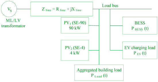
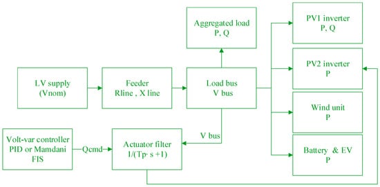
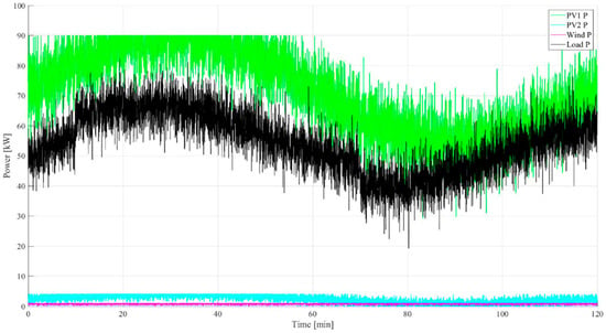
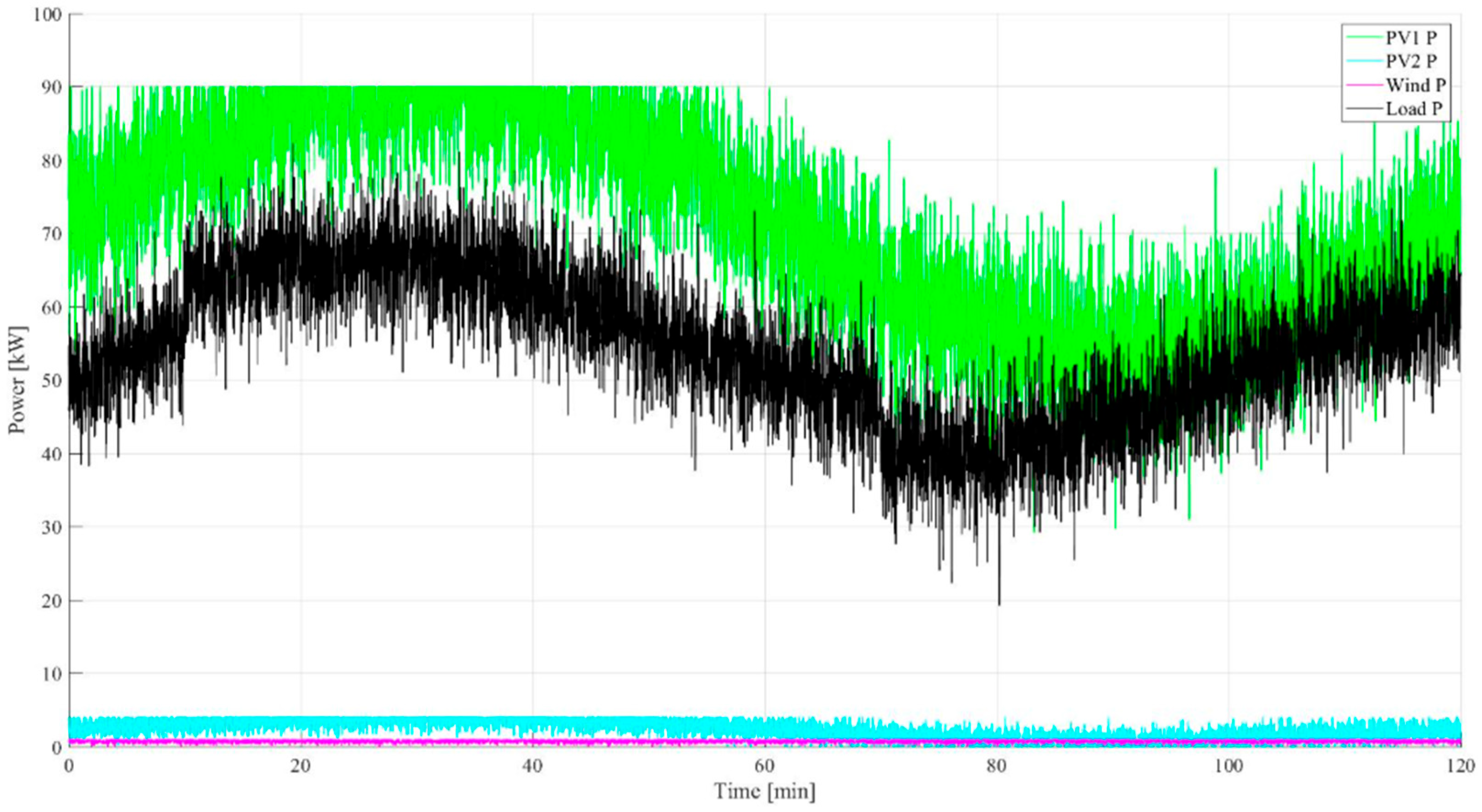
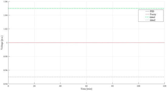
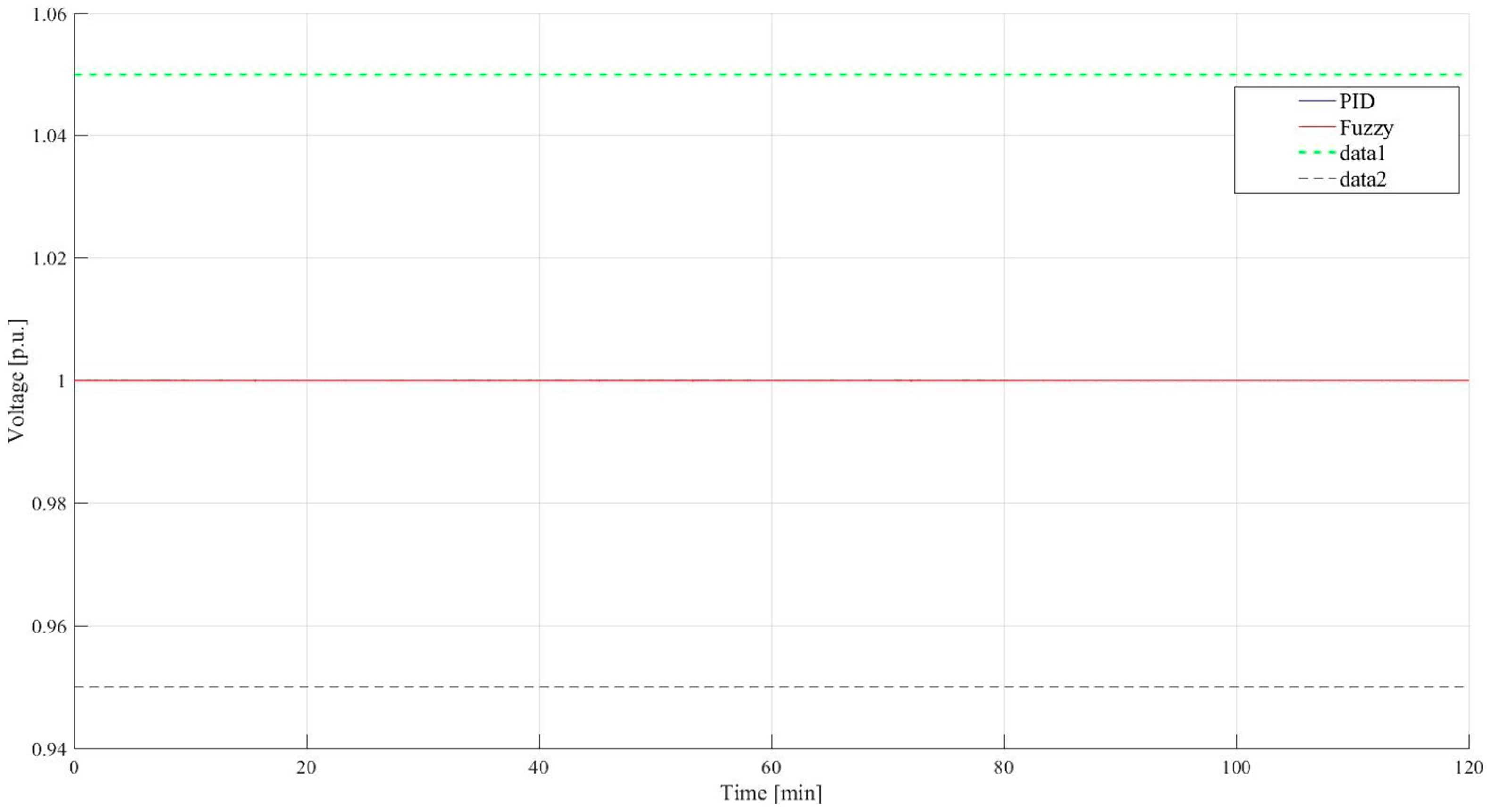
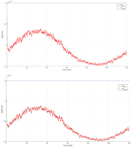

Disclaimer/Publisher’s Note: The statements, opinions and data contained in all publications are solely those of the individual author(s) and contributor(s) and not of MDPI and/or the editor(s). MDPI and/or the editor(s) disclaim responsibility for any injury to people or property resulting from any ideas, methods, instructions or products referred to in the content. |
© 2026 by the authors. Licensee MDPI, Basel, Switzerland. This article is an open access article distributed under the terms and conditions of the Creative Commons Attribution (CC BY) license.