


Abstract
Reliable wireless communication is a key requirement for railway axle-box condition monitoring, particularly in electromagnetically harsh environments where electromagnetic interference (EMI) may degrade diagnostic data transmission. This study proposes an Electromagnetic Compatibility Design Framework (EMCDF) for receiver-oriented assessment of electromagnetic exposure, equivalent EMC mitigation, and wireless-link performance. The framework integrates frequency-domain electromagnetic characterization with analytical radio-link, receiver-noise, residual-interference, and communication-performance models, establishing a physically traceable pathway from prescribed electromagnetic exposure to residual receiver-level interference and the resulting communication degradation. Prescribed in-band EMI scenarios and equivalent EMC-mitigation conditions are evaluated using the signal-to-interference-plus-noise ratio (SINR), theoretical channel capacity, and two proposed normalized electromagnetic robustness metrics based on SINR and theoretical capacity. Under the prescribed analytical scenarios, equivalent in-band EMC attenuation values of 15–20 dB correspond to interference-power reduction factors of approximately 31.6–100. For the adopted 433 MHz radio-link parameters, the model-derived SINR under the severe-EMI scenario decreases from approximately 37.83 dB at 1 km to 17.83 dB at 10 km, while the capacity-based robustness coefficient decreases from approximately 0.474 to 0.299 over the same distance range. The model-based results show that propagation loss and residual EMI influence receiver-level communication performance through physically distinct mechanisms and can therefore be evaluated separately within the proposed framework. The quantitative results represent comparative model-derived estimates rather than experimental validation over the investigated distance range. The proposed EMCDF provides a receiver-oriented analytical methodology for EMC-aware assessment and comparative evaluation of wireless railway condition-monitoring systems.
1. Introduction
The digitalization of railway maintenance increasingly relies on automated condition-monitoring architectures that integrate distributed sensing, embedded processing, wireless telemetry, remote diagnostics, and maintenance decision support [1]. Within this information chain, axle-box assemblies are safety-critical components whose bearings operate under continuously varying mechanical, thermal, and environmental conditions [2]. Reliable transfer of diagnostic information is therefore an integral requirement of automated axle-box condition monitoring rather than an isolated communication task.
Research on axle-box condition assessment has advanced the extraction and interpretation of diagnostic information from vibration and temperature signals, including fault identification, degradation assessment, and thermal-state evaluation [3,4,5,6,7]. In parallel, railway wireless-monitoring studies have addressed autonomous network configuration, distributed sensor nodes, and self-powered onboard monitoring architectures [8,9,10], while previous work by the authors considered digital technologies for thermoregulation and wireless axle-box monitoring [11]. However, these approaches do not explicitly link railway electromagnetic interference and EMC mitigation to receiver-level communication performance within the condition-monitoring information chain.
From an automation perspective, the wireless link forms the communication layer of an end-to-end information chain from sensing and embedded processing to remote monitoring and maintenance decision support. EMI-induced degradation of this link can therefore reduce the reliability of the information available to higher-level monitoring and diagnostic functions, even when sensing and local processing remain operational. This system-level relationship motivates the receiver-oriented EMC assessment developed in the present study.
Electrified railway environments contain numerous sources of conducted and radiated electromagnetic disturbances, including traction converters, switching equipment, power-supply systems, signaling infrastructure, and pantograph–catenary interactions. Previous studies have characterized railway EMI and its effects on radio and electronic systems [12]. Pantograph–catenary arcing can generate broadband transient disturbances [13]. Experimental studies have demonstrated that such disturbances can degrade wireless communication performance [14], while railway-specific methodologies have been proposed for evaluating wireless technologies under transient electromagnetic interference [15]. These findings motivate explicit consideration of electromagnetic disturbances in wireless condition-monitoring analysis rather than reliance solely on conventional propagation and receiver-noise assumptions.
Existing studies therefore address axle-box diagnostics [2,3,4,5,6,7], wireless railway monitoring [8,9,10,11], railway electromagnetic interference [12,13,14,15], and interference-resilient communication architectures [16], but largely as separate research domains. An explicit analytical linkage among electromagnetic exposure, EMC mitigation, residual in-band receiver interference, and quantitative wireless-link performance remains insufficiently developed for axle-box condition-monitoring applications. This integration constitutes the specific research gap addressed in the present study. Railway EMC requirements relevant to a rolling-stock electronic apparatus are established by EN 50121-3-2 and IEC 62236-3-2 [17,18].
To address this gap, this study develops an Electromagnetic Compatibility Design Framework (EMCDF) for wireless railway axle-box condition monitoring. The framework establishes a receiver-oriented analytical path from prescribed electromagnetic exposure and equivalent EMC mitigation to residual in-band interference and communication performance. Its principal methodological contribution is the explicit separation of useful-signal propagation and residual electromagnetic interference as physically distinct analytical paths that are combined only at the receiver level through the communication-performance model.
The principal contributions of this study are as follows:
- –
- A receiver-oriented EMCDF that analytically links prescribed in-band railway EMI scenarios, equivalent EMC mitigation, residual receiver-level interference, and wireless-link performance;
- –
- An EMI-aware radio-link formulation that evaluates the effects of residual in-band interference on SINR, theoretical BER, and theoretical channel capacity;
- –
- Two normalized electromagnetic robustness coefficients for comparative assessment of receiver-level signal-quality degradation and theoretical information-transfer capability.
The quantitative SINR, theoretical BER, channel capacity, and robustness results reported in this study are model-derived under prescribed EMI scenarios and should not be interpreted as direct experimental validation over the investigated 1–10 km communication-distance range. The detailed scope and modeling assumptions are consolidated in Section 2.1.
2. Materials and Methods
2.1. Electromagnetic Compatibility Design Framework (EMCDF)
The proposed Electromagnetic Compatibility Design Framework (EMCDF) treats electromagnetic disturbance, EMC mitigation, wireless communication, and remote condition monitoring as interconnected elements of the automated monitoring architecture. Its receiver-oriented formulation maintains separate analytical paths for useful-signal propagation and residual electromagnetic interference and combines them at the receiver level to evaluate communication-performance degradation.
Scope and assumptions. The present EMCDF is formulated as a system- and receiver-level analytical framework rather than as a component-level electromagnetic-field or EMC-certification model. Qualitative spectral observations from the considered measurement configuration are used to characterize relevant interference behavior, whereas the quantitative EMI levels employed in the subsequent analysis are prescribed analytical scenarios and are not interpreted as direct measurements of interference power over the investigated communication distances. Similarly, the EMC protection chain is represented by an equivalent transfer function describing its aggregate effect on the relevant interference path; it is not treated as a directly measured insertion-loss characteristic of each individual filtering, shielding, grounding, ferrite, or surge-protection component. The resulting SINR, theoretical BER, channel-capacity, and robustness quantities are therefore model-derived performance indicators. Full-wave electromagnetic coupling analysis, component-level EMC certification, and experimental validation of wireless-link performance over the complete distance range considered in the analytical study are outside the scope of the present work. No commercial full-wave electromagnetic simulation software was employed because the present EMCDF is formulated at the system and receiver levels rather than as a geometry-resolved electromagnetic-field model.
As illustrated in Figure 1, the proposed EMCDF comprises five interconnected functional layers: (i) physical sensing, (ii) signal processing, (iii) EMC protection and reliability, (iv) wireless communication, and (v) remote monitoring and diagnostics. In addition to this functional architecture, the framework establishes a quantitative analysis path in which a prescribed interference representation is processed through an equivalent EMC-mitigation response to obtain residual in-band interference. This residual interference is then introduced into the receiver model together with the received signal and receiver-noise contributions to determine the SINR and the associated communication-performance and robustness indicators.
Figure 1.
Functional architecture of the proposed Electromagnetic Compatibility Design Framework (EMCDF) for wireless railway axle-box condition monitoring. Colored blocks distinguish the five principal functional layers, while connecting arrows indicate the functional relationships and information flow among the sensing, processing, EMC-protection, wireless-communication, and remote-monitoring subsystems.
The physical sensing and signal processing layers acquire axle-box temperature and wheelset speed/position information and convert the sensor outputs into structured data suitable for wireless transmission. The considered architecture includes a non-contact infrared temperature sensor, an inductive speed/position sensor, signal conditioning, analog-to-digital conversion, digital preprocessing, and microcontroller-based data handling. Together, these layers establish the sensing and embedded-processing stages of the automated condition-monitoring information chain upstream of the EMC and wireless-communication functions.
The EMC protection and reliability layer represents the measures used to reduce conducted and radiated disturbances before they reach sensitive electronic and communication subsystems. At the architectural level, these measures may include power-line and signal-path filtering, ferrite-based suppression, electromagnetic shielding, controlled grounding, and surge-protection elements. Because individual mitigation mechanisms act through different coupling paths and over different frequency ranges, their aggregate influence on the interference component relevant to the receiver is represented by an equivalent EMC-mitigation transfer function, HEMC(f).
Let SI(f) denote the power spectral density (PSD) of the representative electromagnetic interference before EMC mitigation. Under an equivalent linear time-invariant representation of the relevant interference-coupling and protection path, the residual interference PSD is expressed as:
Here, HEMC(f) is the equivalent amplitude transfer function of the relevant EMC mitigation path, SI(f) is the interference PSD before mitigation, and SI,res(f) is the residual interference PSD after mitigation. Because HEMC(f) is defined in terms of signal amplitude, its effect on power spectral density is represented by the squared magnitude . This formulation provides a compact system-level representation of the aggregate attenuation introduced by the relevant EMC mitigation path. In the present study, HEMC(f) is used as an analytical equivalent and should not be interpreted as a directly measured transfer characteristic of each individual protection component.
Assuming an ideal equivalent receiver passband over the effective bandwidth (B), centered at the communication-channel frequency fc, the residual interference power PI,res is obtained by integrating the residual interference PSD over the receiver passband:
where PI,res is the residual interference power at the receiver input after equivalent EMC mitigation, fc is the center frequency of the communication channel, and (B) is the effective receiver bandwidth. Equation (2) converts the frequency-domain interference representation into the residual in-band interference power required by the receiver-level communication model. It therefore provides the quantitative interface between the prescribed EMI scenario, the equivalent EMC-mitigation model, and the subsequent wireless-link performance analysis.
For the comparative evaluation, the aggregate action of HEMC(f) over the effective receiver band is represented by prescribed equivalent attenuation values. These values are analytical model parameters rather than experimentally measured insertion-loss characteristics and are used to evaluate the effect of different mitigation conditions on residual receiver interference.
The wireless communication layer transfers the processed condition data through the considered 433 MHz EBYTE E90-DTU wireless transceiver (Chengdu Ebyte Electronic Technology Co., Ltd., Chengdu, China), while the remote monitoring and diagnostics layer supports data reception, storage, visualization, alarm generation, and subsequent condition assessment. Within the EMCDF, communication reliability is therefore treated as part of overall monitoring reliability; degradation of the wireless telemetry link can affect the availability of condition information to higher-level monitoring functions, even when sensing and embedded processing remain operational.
The resulting EMCDF therefore links prescribed electromagnetic exposure, equivalent EMC mitigation, residual receiver-level interference, and wireless-link performance while preserving the physical distinction between propagation and EMI-induced receiver degradation. The computational sequence used for the quantitative assessment is summarized in Figure 2.
Figure 2.
Methodological flowchart of the proposed EMCDF showing the separate propagation, electromagnetic-interference, EMC-mitigation, and receiver-level assessment paths. Arrows indicate the direction of the analytical data flow from the model inputs through the propagation and interference paths to the receiver-level performance and robustness assessment.
2.2. System Configuration and Representative Electromagnetic Scenarios
A system-level configuration was considered to evaluate the proposed Electromagnetic Compatibility Design Framework (EMCDF) for wireless railway axle-box condition monitoring. The configuration represents the principal sensing, embedded-processing, EMC-mitigation, and wireless-communication elements introduced in Section 2.1. In parallel, prescribed electromagnetic-interference scenarios were defined as controlled inputs to the analytical communication model developed in Section 2.3, Section 2.4 and Section 2.5. Consistent with the scope defined in Section 2.1, the system configuration and qualitative spectral observations are distinguished from the quantitative EMI levels used for model-based receiver-performance evaluation.
The system architecture, shown in Figure 3, comprises a non-contact infrared temperature sensor, an inductive speed/position sensor, a microcontroller-based processing unit, an EBYTE E90-DTU wireless transceiver, transmitting and receiving antennas, and the EMC-mitigation elements represented within the monitoring architecture. The wireless subsystem operates in the 433 MHz band, with a nominal channel center frequency of fc = 433 MHz. For the comparative radio-link calculations, the transmitter output power was set to Pt = 30 dBm, and nominal transmitting- and receiving-antenna gains of Gt = Gr = 12 dBi were adopted. These parameters were held constant throughout the comparative analysis to provide a common reference radio-link configuration.
Figure 3.
System configuration considered for evaluation of the proposed Electromagnetic Compatibility Design Framework (EMCDF). Line and color conventions are defined in the in-figure legend.
Figure 4 documents the trackside measurement arrangement and field data-acquisition configuration used in the study. These photographs clarify the physical measurement configuration; the quantitative EMI scenarios and distance-dependent communication-performance results remain analytical model outputs as defined in Section 2.1.
Figure 4.
Photographs of the measurement configuration used for the railway monitoring study: (a) trackside measurement arrangement and monitoring unit; (b) field data-acquisition configuration with the measurement unit and computer interface.
The electromagnetic analysis was organized into three stages. The first stage concerned the spectral region associated with the 433 MHz wireless subsystem. A reference spectral representation was considered around the nominal communication channel to illustrate the dominant communication component and the surrounding spectral background. This representation provides a qualitative frequency-domain reference for the wireless subsystem and is not used as evidence of experimentally validated communication performance over the distance range considered in the analytical model.
The representative reference spectrum associated with the 433 MHz wireless subsystem is shown in Figure 5.
Figure 5.
Reference spectral representation of the 433-MHz wireless communication subsystem used for EMCDF evaluation. The blue solid line represents the reference spectral power level, while the vertical dashed lines indicate the boundaries of the considered frequency band.
The second stage considered the broader electromagnetic environment. Representative wideband spectral conditions were examined over the 500 MHz–2.4 GHz range to illustrate the frequency-dependent and nonuniform character of electromagnetic disturbances relevant to railway electronic and wireless systems. Previous railway EMC investigations have reported the broadband backgrounds, localized spectral components, switching-related disturbances, and transient electromagnetic phenomena associated with traction and power-supply systems [12,13,19,20]. The wideband representations therefore include a nonuniform spectral background together with localized spectral components of different amplitudes.
For visualization, the 500 MHz–2.4 GHz range was divided into two intervals: 500 MHz–1 GHz and 1–2.4 GHz, as shown in Figure 6a,b. These wideband representations are used to illustrate the broader frequency-dependent electromagnetic environment and should not be interpreted as direct quantitative inputs to the 433 MHz receiver calculation because the illustrated frequency range does not include the nominal channel center frequency of fc = 433 MHz. The quantitative receiver-level interference conditions are therefore defined separately as prescribed in-band model scenarios.
Figure 6.
Representative wideband electromagnetic-interference spectra used to illustrate the frequency-dependent electromagnetic environment: (a) 500 MHz–1 GHz; (b) 1–2.4 GHz.
The third stage defined the quantitative interference conditions used in the receiver-level analytical model. Only electromagnetic disturbance falling within, or equivalently coupled into, the effective receiver bandwidth (B) around fc contributes directly to the in-band interference term used in the SINR calculation. In accordance with Equations (1) and (2), the representative pre-mitigation interference PSD SI(f) is transformed through the equivalent EMC response HEMC(f), yielding the residual interference PSD SI,res(f) and the corresponding residual in-band interference power PI,res.
For the quantitative receiver-level evaluation, four prescribed electromagnetic-interference scenarios were defined: baseline EMI, moderate EMI, high EMI, and severe EMI. The corresponding pre-mitigation in-band interference powers PI were set to −88, −73, −64, and −55 dBm, respectively. For comparative model evaluation, equivalent in-band EMC attenuation values AEMC of 15, 16, 18, and 20 dB, respectively, were assigned to these scenarios. The complete parameterization is summarized in Table 1.
Table 1.
Prescribed EMI and equivalent EMC-mitigation parameters used in the comparative analysis.
The scenario labels denote relative interference severity only within the present comparative analysis and do not represent standardized railway EMC classifications. The prescribed PI and AEMC values are analytical model inputs rather than field-measured quantities or limits specified in EN 50121-3-2 and IEC 62236-3-2 [17,18]. The paired values define controlled comparative cases and do not imply a physical dependence between interference severity and mitigation effectiveness.
For each prescribed scenario, the residual in-band interference power is calculated in linear power units as:
where PI is the prescribed pre-mitigation in-band interference power, PI,res is the residual in-band interference power after equivalent EMC mitigation, and AEMC is the equivalent in-band EMC attenuation expressed in decibels. In Equation (3), PI and PI,res must be expressed in the same linear power units, such as W or mW. Equation (3) represents the band-equivalent form of the frequency-domain formulation introduced in Equation (2) when the aggregate effect of HEMC(f) over the effective receiver bandwidth is represented by a single equivalent attenuation value.
When the interference powers are expressed logarithmically in dBm, the corresponding relation is:
Thus, Equation (3) is used for linear power quantities, whereas Equation (4) provides the equivalent calculation when interference power is expressed in dBm. This distinction avoids applying a linear attenuation factor directly to logarithmic power quantities.
For the prescribed scenario parameters in Table 1, application of Equation (4) yields residual interference levels from −103 to −75 dBm across the baseline, moderate, high, and severe EMI scenarios, respectively. These values are model-derived outputs of the equivalent EMC-mitigation stage and are subsequently introduced into the receiver-level communication analysis.
The same radio-link parameters and receiver-model assumptions were maintained across the four scenarios so that differences in the calculated communication-performance indicators could be traced to the prescribed interference conditions and equivalent EMC-mitigation parameters. The four scenarios therefore constitute controlled analytical cases rather than experimentally reproduced railway operating states.
This parameterization provides a consistent analytical dataset for evaluating the internal behavior of the EMCDF. The prescribed interference conditions and corresponding residual in-band interference powers are subsequently combined with the radio-link and receiver-noise models to calculate the SINR, theoretical BER, theoretical channel capacity, and electromagnetic robustness coefficients. Accordingly, the resulting communication-performance quantities represent model-derived comparative results rather than direct field measurements of wireless-link behavior.
2.3. Mathematical Radio-Channel and EMI Model
A mathematical radio-channel and electromagnetic-interference model was developed to quantify the influence of the prescribed railway electromagnetic conditions and equivalent EMC mitigation on wireless axle-box condition-monitoring performance. Unlike a conventional link-budget analysis focused primarily on useful-signal propagation, the present formulation explicitly combines propagation loss, receiver thermal noise, residual in-band electromagnetic interference, and communication-quality indicators within a common receiver-level model.
The model follows the physical signal-transmission process represented by the EMCDF and is organized into three interconnected analytical levels. Level I—physical radio propagation determines propagation loss and useful received-signal power. Level II—receiver disturbance determines the intrinsic receiver-noise contribution and incorporates the residual in-band interference obtained from the equivalent EMC-mitigation model introduced in Section 2.1 and Section 2.2. Level III—communication-quality assessment relates the resulting useful-signal and disturbance powers to SINR, theoretical bit-error probability, and theoretical channel capacity. This organization preserves a traceable distinction between useful-signal attenuation and interference-induced communication degradation.
2.3.1. Received-Signal Power and Propagation Loss
The useful received-signal power is determined using a conventional radio-link budget. In logarithmic form:
where Pt and Pr are the transmitted and received powers, respectively; Gt and Gr are the transmitting- and receiving-antenna gains; Lp is the propagation loss; and Lsys represents implementation-related system losses.
For an unobstructed line-of-sight reference link, the propagation loss is calculated using the free-space path-loss model in accordance with ITU-R P.525 [21]:
where fMHz is the carrier frequency expressed in MHz and dkm is the transmitter–receiver separation expressed in km. The constant 32.45 results from this specific combination of frequency and distance units.
LFSPL = 32.45 + 20log10(fMHz) + 20log10(dkm).
For the wireless monitoring configuration considered in this study, the nominal channel center frequency is fc = 433 MHz. Because practical railway environments may introduce additional attenuation through metallic rolling-stock structures, trackside infrastructure, partial obstruction, reflections, diffraction, and antenna-placement effects, the total propagation loss is represented as:
where Lenv denotes an additional environment-dependent propagation-loss term relative to the free-space reference and is expressed in dB.
Lp = LFSPL + Lenv
The implementation-related term Lsys is treated separately from Lenv and may account for cable attenuation, connector losses, antenna mismatch, and other hardware-dependent losses. This distinction enables propagation-related and implementation-related attenuation mechanisms to be represented independently within the radio-link budget.
Electromagnetic interference is not incorporated into Lp, Lenv, or Lsys. These terms determine the useful received-signal power Pr, whereas residual electromagnetic interference is introduced independently into the receiver-disturbance model. This separation prevents double counting and preserves the physical distinction between useful-signal attenuation and interference-induced receiver degradation.
2.3.2. Receiver Disturbance Model
The receiver-level disturbance is represented by two contributions: intrinsic receiver thermal noise and residual in-band electromagnetic interference remaining after equivalent EMC mitigation. The total effective disturbance power is therefore:
where NT denotes the receiver thermal-noise power and PI,res is the residual in-band interference power defined in Section 2.1 and Section 2.2.
Ntot = NT + PI,res
The receiver thermal-noise contribution is calculated as:
where k = 1.380649 × 10⁻²³ J/K is the Boltzmann constant, T0 is the reference equivalent noise temperature, (B) is the effective receiver noise bandwidth, and (F) is the receiver noise factor expressed as a dimensionless linear quantity. For the conventional reference temperature T0 = 290 K, the available thermal-noise power spectral density kT0 is approximately −174 dBm/Hz before inclusion of the receiver noise figure.
NT = kT0BF.
If the receiver-noise specification is provided as a noise figure (NF) in decibels, the corresponding linear noise factor used in Equation (9) is:
F = 10NF/10.
The residual electromagnetic-interference contribution PI,res is obtained from the frequency-domain formulation in Equation (2) or, for the prescribed band-equivalent scenarios, from Equations (3) and (4). Thus, the receiver-disturbance model uses the same residual-interference quantity established in Section 2.1 and Section 2.2 and does not introduce an additional independent EMI variable.
Only disturbance contributions referred to the RF receiver input are included in Ntot. Noise originating in the sensor-acquisition or analog-to-digital conversion chain is not included in the RF receiver-disturbance budget unless an explicit input-referred coupling model between those subsystems and the RF receiver is available. This prevents noise contributions from physically distinct signal paths from being combined without a defined transfer relationship.
2.3.3. Receiver-Level SNR and SINR
The received power obtained from Equation (5) is converted from dBm to watts before the receiver-level performance calculations:
Because the receiver is affected by both intrinsic thermal noise and residual in-band electromagnetic interference, the signal-to-interference-plus-noise ratio is defined as:
For the intrinsic receiver-noise reference, in which the external interference contribution is set to zero, the corresponding signal-to-noise ratio is:
Both SINR and SNR0 are dimensionless linear power ratios. Their logarithmic forms are:
SINRdB = 10log10(SINR), SNR0,dB = 10log10(SNR0).
The distinction between SNR0 and SINR separates the intrinsic receiver-noise limitation from degradation associated with residual electromagnetic interference. The useful received power Pr is determined by the propagation model, whereas PI,res is obtained independently from the equivalent EMC-mitigation model.
2.3.4. Theoretical Bit-Error Probability Under an Equivalent Gaussian Disturbance Approximation
Railway electromagnetic interference may include transient, impulsive, and spectrally localized components, particularly in environments affected by traction-system switching and pantograph–catenary arcing [12,13,14,15]. Standard additive white Gaussian noise error-probability expressions therefore cannot be interpreted as exact statistical descriptions of all railway EMI conditions.
For comparative model evaluation, the aggregate residual disturbance is approximated by an equivalent zero-mean Gaussian disturbance having the same effective in-band power. This Equivalent Gaussian Disturbance (EGD) approximation enables standard analytical error-probability relations to be used as comparative performance indicators while avoiding the assumption that the strongly impulsive railway EMI is itself Gaussian.
For the analytical conversion from receiver SINR to an effective bit-energy-to-disturbance-density ratio, the equivalent Gaussian disturbance is assumed to have an approximately uniform effective power spectral density over the receiver bandwidth (B). Under this assumption:
while the received bit energy is:
where Rb is the information bit rate. Combining Equations (12), (15) and (16) gives:
This relationship is therefore conditional on the equivalent-bandwidth approximation and is used here to provide a consistent mapping between receiver-level SINR and theoretical modulation-performance indicators.
Standard analytical BER expressions for coherent BPSK/QPSK and square \( M\) -QAM under Gaussian disturbance are adopted from classical digital-communication theory [22].
where Q(⋅) denotes the Gaussian Q-function.
For square (M)-QAM with Gray coding under the same equivalent Gaussian-disturbance approximation, the theoretical bit-error probability is approximated as:
This commonly used analytical approximation is employed here for comparative assessment of modulation sensitivity rather than as a hardware-specific prediction of packet-error performance. Its interpretation is most appropriate in the operating region where the underlying Gaussian-disturbance and nearest-neighbor error approximations are valid.
The QPSK, 16-QAM, and 64-QAM cases are considered exclusively as analytical modulation scenarios for evaluating the sensitivity of theoretical communication reliability to EMI-induced degradation. They are not presented as modulation modes physically implemented by the EBYTE E90-DTU transceiver unless independently confirmed for the specific hardware configuration.
Accordingly, the BER values obtained from Equations (18) and (19) are theoretical, model-derived indicators. Particular caution is required for scenarios dominated by impulsive or transient electromagnetic disturbances, for which equal in-band disturbance power does not necessarily imply identical error statistics.
2.3.5. Theoretical Channel Capacity
Under the same equivalent Gaussian-disturbance approximation, an information-theoretic reference capacity is evaluated using the Shannon–Hartley relationship [23]:
where C is the theoretical reference capacity in bit/s, (B) is the effective receiver bandwidth in Hz, and SINR is expressed as a dimensionless linear power ratio.
C = Blog2(1 + SINR)
For the intrinsic receiver-noise reference condition, the corresponding theoretical reference capacity is:
C0 = Blog2(1 + SNR0).
The quantities C and C0 represent information-theoretic reference limits under the adopted equivalent Gaussian-disturbance model and should not be interpreted as the practical data throughput of the EBYTE E90-DTU transceiver. Actual throughput additionally depends on modulation and coding, packet structure, synchronization, retransmission mechanisms, protocol overhead, channel access, and hardware-specific constraints. Furthermore, because real railway electromagnetic disturbances may depart substantially from the equivalent Gaussian representation, Equation (20) is used as a comparative analytical metric rather than as an exact capacity characterization of a railway wireless channel under arbitrary EMI.
2.4. Electromagnetic Robustness Metrics
To provide normalized measures of wireless-link resilience under residual electromagnetic interference, two dimensionless electromagnetic robustness coefficients are introduced. The first coefficient quantifies the fraction of receiver-level signal quality retained in the presence of residual in-band interference, whereas the second characterizes the corresponding fraction of theoretical information-transfer capability retained under the same electromagnetic condition.
Both metrics are defined relative to an interference-free reference condition evaluated for the same useful received-signal power Pr, effective receiver bandwidth (B), and intrinsic receiver-noise characteristics. This normalization separates EMI-induced degradation from conventional propagation-related attenuation and provides a consistent basis for comparing the prescribed electromagnetic scenarios and equivalent EMC-mitigation conditions considered in the present study.
2.4.1. SINR-Based Electromagnetic Robustness Coefficient
The first robustness metric is defined as the ratio of the EMI-affected SINR to the corresponding interference-free reference SNR. Using the definitions introduced in Section 2.3.3:
Substitution of Equations (12) and (13) gives:
Here, NT represents the intrinsic receiver-noise power and PI,res is the residual in-band electromagnetic-interference power after equivalent EMC mitigation. For non-negative residual interference power and NT > 0:
The limiting value is obtained when PI,res = 0, corresponding to the interference-free reference condition. Progressively smaller values indicate the increasing receiver-level degradation associated with residual EMI.
An important property of Equation (23) is that the useful received-signal power Pr cancels when the ratio SINR/SNR0 is formed. Consequently, for fixed NT and PI,res, is independent of useful-signal propagation loss and transmission distance. This property is intentional because the coefficient is designed to isolate the relative receiver-level degradation attributable to residual in-band interference rather than to characterize overall radio-link quality.
Accordingly, variations in among the prescribed analytical scenarios reflect changes in the relationship between residual interference power and the intrinsic receiver-noise floor. Within the proposed EMCDF, therefore serves as a normalized receiver-level electromagnetic robustness metric.
2.4.2. Capacity-Based Electromagnetic Robustness Coefficient
The second robustness metric quantifies the information-theoretic consequence of residual electromagnetic interference under the equivalent Gaussian-disturbance model adopted in Section 2.3. Using the theoretical reference capacities defined in Section 2.3.5, the capacity-based electromagnetic robustness coefficient is defined as:
Substituting Equations (20) and (21) yields:
For the same useful received-signal power and intrinsic receiver-noise conditions, the presence of non-negative residual interference implies:
SINR ≤ SNR0
Consequently, for Pr > 0:
The limiting value is obtained when PI,res = 0, whereas values below unity indicate a reduction in the theoretical information-transfer capability associated with residual EMI.
The common multiplicative bandwidth term (B) cancels explicitly in the ratio in Equation (25), making dimensionless. This algebraic cancelation should not, however, be interpreted as implying complete independence from receiver bandwidth, because (B) also contributes to the thermal-noise power NT = kT0BF and may affect the integrated residual interference power PI,res. For a fixed receiver configuration and fixed values of NT and PI,res, Equation (25) provides a normalized comparison of the EMI-affected and interference-free theoretical reference capacities.
Unlike , the capacity-based coefficient generally retains an indirect dependence on the useful received-signal power Pr through both SINR and SNR0. Consequently, even for fixed NT and PI,res, may vary as the propagation conditions change and Pr decreases.
The same residual interference power can therefore produce different relative reductions in theoretical information-transfer capability depending on the operating signal-to-noise regime of the wireless link. This property distinguishes from and enables the two coefficients to characterize complementary aspects of electromagnetic robustness.
2.4.3. Interpretation of the Robustness Metrics
The proposed robustness coefficients characterize two related but distinct consequences of residual electromagnetic interference. The SINR-based coefficient represents the fraction of receiver-level signal quality retained relative to the interference-free reference condition. Because Pr cancels analytically, this coefficient depends on the relationship between the residual in-band interference power PI,res and the intrinsic receiver-noise power NT under the adopted receiver model.
The capacity-based coefficient , in contrast, represents the fraction of theoretical reference capacity retained under the same electromagnetic condition. Owing to the logarithmic dependence of the Shannon–Hartley expression on signal quality, does not vary linearly with residual interference and generally retains dependence on the useful received-signal level. The two coefficients therefore characterize complementary aspects of EMI-induced communication degradation and should not be interpreted interchangeably.
2.5. Model Parameterization and Evaluation Procedure
The model was evaluated using the radio-link parameters and prescribed electromagnetic scenarios defined above. The procedure comprised the calculation of useful received-signal power, receiver noise and residual interference, receiver-level SINR, and theoretical communication-performance quantities, followed by evaluation of the proposed robustness coefficients.
2.5.1. Model Input Parameters
The analytical model was parameterized using the carrier frequency fc, transmitter power Pt, transmitting- and receiving-antenna gains Gt and Gr, transmitter–receiver separation d, effective receiver bandwidth B, system loss Lsys, reference temperature T0, and receiver noise figure NF. For the configuration considered in this study, the nominal carrier frequency was fc = 433 MHz, consistent with the EBYTE E90-DTU communication subsystem described in Section 2.2.
For the baseline comparative evaluation, the principal model parameters were set to Pt = 30 dBm, Gt = Gr = 12 dBi, B = 125 kHz, Lsys = 6 dB, T0 = 290 K, and NF = 6 dB. The transmitter–receiver distance (d) was varied from 1 to 10 km to examine the distance-dependent behavior of the analytical radio-link model. The baseline parameter set is summarized in Table 2.
Table 2.
Reference radio-link and receiver parameters used in the comparative model evaluation.
The useful received-signal power was calculated using the link-budget formulation in Equation (5). For the baseline analytical evaluation, propagation loss was represented by the free-space path-loss model in Equation (6), with the environmental correction term in Equation (7) set to Lenv = 0 dB. Accordingly, Lp = LFSPL for the baseline calculations.
This assumption defines an idealized free-space propagation baseline. Consequently, the calculations over the 1–10 km distance range represent reference propagation cases rather than site-specific railway coverage predictions. Additional losses associated with railway infrastructure, vehicle-body obstruction, antenna installation, multipath propagation, diffraction, and shadowing are not explicitly quantified in the present baseline model. The term Lenv is retained in the general formulation to permit future incorporation of such site-specific propagation effects when independently determined data become available.
The electromagnetic component of the model was parameterized using four prescribed in-band interference scenarios: baseline EMI, moderate EMI, high EMI, and severe EMI. Their corresponding pre-mitigation interference powers PI were −88, −73, −64, and −55 dBm, respectively. Equivalent in-band EMC attenuation values AEMC of 15, 16, 18, and 20 dB were assigned to these scenarios. Application of Equations (3) and (4) yields residual interference powers PI,res of −103, −89, −82, and −75 dBm, respectively.
The term baseline EMI denotes the lowest prescribed interference scenario used in the comparative analysis and should not be confused with the interference-free reference condition defined by PI,res = 0. The scenario labels indicate relative interference severity within the present analytical study and do not constitute standardized railway EMC classifications.
The prescribed interference powers and equivalent attenuation values are comparative model inputs rather than independently reproduced field measurements or emission/immunity limits specified by railway EMC standards. Similarly, AEMC represents the assumed aggregate effectiveness of the equivalent EMC-mitigation path rather than experimentally measured insertion loss of an individual protection component.
The parameterization therefore establishes two physically distinct computational paths. The first determines Pr from the transmitter characteristics, antenna gains, system losses, and propagation distance. The second determines PI,res from the prescribed pre-mitigation interference power PI and the equivalent EMC attenuation AEMC. These two paths are combined at the receiver-disturbance stage through the SINR formulation.
2.5.2. Evaluation Procedure
For each transmission distance and prescribed EMI scenario, the useful received-signal power was calculated using Equations (5)–(7), while intrinsic receiver noise and residual in-band interference were evaluated using Equations (8)–(11). The resulting SNR and SINR were obtained from Equations (12)–(14). Theoretical BER and reference capacity were subsequently evaluated using Equations (15)–(21) under the assumptions stated in Section 2.3, and the electromagnetic robustness coefficients were calculated using Equations (22)–(25).
The interference-free reference condition was defined by PI,res = 0, whereas the EMI-affected conditions used the residual interference levels corresponding to the prescribed scenarios in Table 1. All quantities were evaluated within a common receiver configuration to enable direct comparative assessment.
2.5.3. Model Consistency Criteria
Because the quantitative EMI conditions are prescribed analytical scenarios, model evaluation focuses on physical consistency and comparative sensitivity rather than independent experimental validation. The expected trends are as follows: increasing transmission distance should reduce Pr without directly changing the prescribed PI,res; increasing PI,res at fixed Pr should reduce SINR; and increasing AEMC at fixed PI should reduce the residual interference power.
In addition:
with remaining independent of transmission distance for fixed NT and PI,res, whereas may vary with the useful received-signal level. These criteria are used to assess the internal consistency of the model outputs reported in Section 3.
3. Results
The results are presented according to the analytical sequence of the EMCDF. First, the frequency-domain characteristics relevant to the prescribed EMI conditions are examined. The effect of equivalent EMC mitigation on residual receiver interference is then quantified, followed by evaluation of distance-dependent SNR, SINR, theoretical communication performance, and the proposed electromagnetic robustness coefficients.
3.1. Electromagnetic Characterization and Representative EMI Scenarios
The wideband spectral representations in Figure 6 show a nonuniform electromagnetic background over the investigated 500 MHz–2.4 GHz range, with broadband components and localized spectral variations whose distribution changes with frequency. These qualitative observations support the frequency-selective treatment adopted in the EMCDF. Because the illustrated wideband intervals do not include the nominal 433 MHz receiver center frequency, they are not used directly as quantitative inputs to the receiver-level calculations.
The 433 MHz subsystem is therefore considered separately. Figure 5 provides the qualitative reference spectrum of the wireless subsystem, whereas Figure 7 illustrates the prescribed in-band spectral conditions used to represent increasing EMI severity around the communication channel.
Figure 7.
Representative in-band spectral distributions associated with the prescribed EMI scenarios around the 433 MHz wireless communication channel. The blue, red, yellow, and purple curves represent baseline, moderate, high, and severe EMI scenarios, respectively.
Consistent with the scope defined in Section 2.1, Figure 5, Figure 6 and Figure 7 provide qualitative or prescribed spectral representations and are not interpreted as experimental validation of wireless-link performance over the investigated distance range.
For receiver-level evaluation, the relevant disturbance quantity is the in-band interference power PI within, or equivalently coupled into, the effective receiver bandwidth B, rather than the maximum spectral amplitude observed over the broader electromagnetic environment.
Because the original numerical spectrum-analyzer datasets were unavailable for complete retrospective reprocessing, quantitative in-band interference powers could not be reconstructed directly from the original wideband observations. The receiver-level evaluation therefore uses the prescribed EMI conditions defined in Table 1, which span pre-mitigation interference powers from −88 dBm for baseline EMI to −55 dBm for severe EMI over the adopted receiver bandwidth of B = 125 kHz.
The prescribed in-band scenarios defined in Table 1 are subsequently transformed through the equivalent EMC-mitigation stage, and the resulting residual interference levels are evaluated in Section 3.2.
3.2. Effect of the Equivalent EMC Mitigation Chain
The effect of equivalent EMC mitigation was evaluated by transforming the prescribed pre-mitigation interference power PI into the residual receiver-level interference power PI,res using Equations (3) and (4). For the four prescribed EMI scenarios, the equivalent in-band attenuation values AEMC range from 15 to 20 dB. The resulting residual interference levels are summarized in Table 3.
Table 3.
Prescribed pre-mitigation and calculated residual in-band interference powers for the investigated EMCDF scenarios.
The prescribed attenuation reduces the in-band interference by 15–20 dB, corresponding to interference-power reduction factors of approximately 31.6–100. The calculated residual interference ranges from −103 dBm for baseline EMI to −75 dBm for severe EMI.
The corresponding pre- and post-mitigation interference levels are illustrated in Figure 8.
Figure 8.
Prescribed pre-mitigation and calculated residual in-band interference powers for the investigated EMCDF scenarios.
The results also show that equivalent attenuation alone does not determine the final receiver-level electromagnetic condition. Although the severe-EMI scenario is assigned the largest attenuation (20 dB), its residual interference remains −75 dBm, which is 14 dB higher than the −89 dBm obtained under moderate EMI. This occurs because the severe scenario starts from a substantially higher prescribed pre-mitigation interference level. Consequently, receiver-level EMC assessment must consider both PI and the resulting PI,res, rather than AEMC alone.
Because PI,res is treated independently of useful-signal propagation, its communication impact depends on the received-signal level and is evaluated together with distance-dependent Pr in Section 3.3.
3.3. Radio-Link Performance Under Electromagnetic Interference
The influence of residual electromagnetic interference on receiver-level wireless-link performance was evaluated using the propagation and receiver-disturbance models developed in Section 2.3. The analysis was performed over transmitter–receiver distances from 1 to 10 km using the residual interference powers obtained from the prescribed EMI and equivalent EMC-mitigation scenarios considered in Section 3.1 and Section 3.2.
For the comparative model evaluation, the carrier frequency was fc = 433 MHz, the transmitter output power was Pt = 30 dBm, and the transmitting- and receiving-antenna gains were Gt = Gr = 12 dBi. The effective receiver bandwidth was B = 125 kHz, consistent with the in-band interference analysis, while the system loss and receiver noise figures were Lsys = 6 dB and NF = 6 dB, respectively, as specified in Section 2.5.
At the reference temperature T0 = 290 K, the adopted bandwidth and noise figure yield an intrinsic receiver-noise power of approximately NT = 1.99 × 10⁻¹⁵ W, or NT ≈ −117.01 dBm. This value represents the intrinsic receiver-noise reference against which the additional contribution of residual in-band electromagnetic interference was evaluated.
The useful received-signal power Pr was calculated using the link-budget formulation introduced in Section 2.3. Consistent with the baseline assumptions defined in Section 2.5, the environmental propagation correction was set to Lenv = 0 dB; therefore, propagation loss was represented by the free-space path-loss model. Under this idealized baseline assumption, the calculated path loss increases from approximately 85.17 dB at 1 km to 105.17 dB at 10 km. Consequently, the useful received-signal power decreases from approximately −37.17 dBm at 1 km to −57.17 dBm at 10 km.
The corresponding interference-free reference SNR, SNR0, and EMI-affected SINR values are summarized in Table 4.
Table 4.
Model-derived receiver-level SNR and SINR as functions of transmission distance under the prescribed EMI scenarios.
As shown in Table 4, two physically distinct mechanisms determine the calculated receiver-level signal quality. Increasing the propagation distance reduces the useful received-signal power Pr and therefore decreases the interference-free reference SNR0. Residual electromagnetic interference, in contrast, increases the total receiver disturbance power and reduces the corresponding SINR relative to the interference-free reference condition.
Across the 1–10 km distance range, the calculated SINR decreases by approximately 20 dB for each prescribed EMI scenario. At 1 km, the SINR ranges from 65.66 dB under baseline EMI to 37.83 dB under severe EMI, whereas at 10 km, the corresponding values are 45.66 and 17.83 dB. The severe-EMI scenario therefore produces the lowest receiver-level signal quality throughout the investigated range.
The calculated SNR and SINR values exhibit approximately parallel distance-dependent decreases under the adopted model assumptions. This behavior follows directly from the analytical structure of the EMCDF: for each electromagnetic scenario, PI,res is held constant, whereas Pr decreases with propagation distance. Consequently, the difference between the interference-free reference SNR and each EMI-affected SINR is determined by the corresponding residual receiver-disturbance level.
This behavior preserves the intended physical separation between propagation- and EMI-induced degradation: propagation loss modifies Pr, whereas PI,res modifies the receiver disturbance without being treated as an additional propagation loss. The two mechanisms are combined only in the receiver-level SINR calculation.
The severe-EMI scenario provides a representative example. Following the prescribed 20 dB equivalent attenuation considered in Section 3.2, the residual in-band interference power is approximately −75 dBm. At 1 km, the useful received-signal power is approximately −37.17 dBm, resulting in a calculated SINR of 37.83 dB. At 10 km, Pr decreases to approximately −57.17 dBm, while PI,res remains fixed at −75 dBm under the prescribed scenario, reducing the calculated SINR to 17.83 dB.
The distance-dependent quantities reported in Table 4 are model-derived results obtained using the specified link-budget parameters, the idealized free-space propagation baseline, and the prescribed residual EMI scenarios. They should therefore be interpreted as comparative analytical results rather than experimental verification of a 1–10 km railway communication range or site-specific coverage.
Overall, the results preserve the intended separation between useful-signal propagation and residual electromagnetic interference within the proposed framework. Propagation determines Pr, whereas the residual interference PI,res modifies the total receiver disturbance and consequently the calculated SINR. These receiver-level quantities provide the basis for evaluating the electromagnetic robustness metrics in Section 3.4.
3.4. Electromagnetic Robustness and Communication-Performance Assessment
The receiver-level consequences of residual electromagnetic interference were further evaluated using the two normalized robustness coefficients introduced in Section 2.4. The SINR-based electromagnetic robustness coefficient quantifies the fraction of receiver-level signal quality retained relative to the interference-free reference condition, whereas the capacity-based coefficient characterizes the corresponding fraction of theoretical information-transfer capability retained under the same electromagnetic condition.
According to Equation (23), depends on the relationship between the intrinsic receiver-noise power NT and the residual in-band interference power PI,res. Because the useful received-signal power Pr cancels analytically from the ratio SINR/SNR0, the coefficient remains independent of transmission distance when NT and PI,res are fixed. This behavior distinguishes from the absolute SINR, which decreases with distance as the useful received-signal power decreases.
Using the residual interference powers reported in Table 4 and the intrinsic receiver-noise power of approximately −117.01 dBm determined in Section 3.3, the resulting SINR-based electromagnetic robustness coefficients are summarized in Table 5.
Table 5.
SINR-based electromagnetic robustness coefficients for the representative residual EMI conditions.
As shown in Table 5, decreases monotonically as the prescribed residual interference power increases, from 0.0382 under baseline EMI to 6.29 × 10⁻⁵ under severe EMI. This trend reflects the increasing contribution of residual interference relative to the receiver-noise reference condition.
The small numerical values of should not be interpreted directly as communication-availability probabilities or threshold indicators. The coefficient is a normalized linear-domain degradation metric referenced to the thermal-noise-limited receiver condition. In particular, it quantifies the fraction of receiver-level signal quality retained when residual interference is added to the intrinsic receiver thermal noise, rather than whether a specific communication link remains operational.
This distinction is illustrated by the severe-EMI scenario. Although is approximately 6.29 × 10⁻⁵, the corresponding model-derived SINR remains 37.83 dB at 1 km and 17.83 dB at 10 km, as reported in Table 4. The coefficient should therefore be interpreted together with the absolute receiver-level SINR rather than as a standalone indicator of communication availability.
The capacity-based electromagnetic robustness coefficient provides a complementary information-theoretic interpretation. According to Equation (25),
The capacity-based coefficient provides a complementary information-theoretic measure. Unlike , it generally varies with transmission distance, even when PI,res remains fixed, because the useful received-signal power affects both SINR and SNR0. The resulting values are summarized in Table 6.
Table 6.
Capacity-based electromagnetic robustness coefficients as functions of transmission distance and prescribed EMI scenario.
The capacity-based robustness coefficient decreases with the transmission distance for all prescribed EMI scenarios. Under baseline EMI, decreases from 0.822 at 1 km to 0.763 at 10 km, whereas under severe EMI, it decreases from 0.474 to 0.299 over the same distance range. The severe-EMI scenario therefore produces the largest relative reduction in theoretical information-transfer capability throughout the investigated range.
The capacity-based reduction is less pronounced than the corresponding reduction in because theoretical capacity depends logarithmically on signal quality. Consequently, a large reduction in the linear SINR-to-SNR ratio does not produce an equally large proportional reduction in theoretical reference capacity.
The difference between the two robustness metrics follows from their distinct mathematical definitions. The SINR-based coefficient quantifies the fraction of receiver-level signal quality retained in the presence of residual interference relative to the interference-free reference condition. The capacity-based coefficient , in contrast, maps the EMI-affected and interference-free receiver conditions through the logarithmic Shannon–Hartley relation. Consequently, a large reduction in the linear SINR-to-SNR ratio does not produce an equally large proportional reduction in the theoretical reference capacity.
The distance-dependent behavior of is illustrated in Figure 9.
Figure 9.
Capacity-based electromagnetic robustness coefficient as a function of transmission distance for the prescribed EMI scenarios.
As shown in Figure 9, decreases with an increasing transmission distance for all prescribed EMI scenarios, with severe EMI producing the lowest retained theoretical reference capacity throughout the investigated range. In contrast, remains constant with the distance for each fixed residual-interference condition under the adopted model assumptions. The two coefficients therefore provide complementary normalized measures of residual EMI effects: characterizes receiver-level signal-quality degradation relative to the interference-free reference condition, whereas describes the corresponding reduction in theoretical information-transfer capability as the useful received-signal level varies.
4. Discussion
The model-based results demonstrate the analytical utility of the proposed Electromagnetic Compatibility Design Framework (EMCDF) for linking prescribed electromagnetic exposure, equivalent EMC mitigation, residual receiver-level interference, and wireless-link performance in railway axle-box condition monitoring. The principal contribution is not a new propagation model or an individual EMC protection technique, but a receiver-oriented analytical framework that connects these established engineering domains through physically traceable quantities.
A key methodological feature of the EMCDF is the distinction between the broader electromagnetic environment and receiver-relevant in-band interference. The equivalent frequency-dependent response HEMC(f) maps the pre-mitigation interference spectrum to the residual interference within the effective receiver bandwidth, thereby providing an analytical interface between electromagnetic-environment characterization and receiver-level communication assessment. Filtering, shielding, grounding, ferrite-based suppression, and surge protection are therefore represented through their aggregate effect rather than being assigned separate experimentally unsupported attenuation characteristics.
The prescribed scenarios illustrate that equivalent attenuation alone does not determine the final receiver-level electromagnetic condition. Although the severe-EMI scenario is assigned the largest equivalent attenuation of 20 dB, its residual interference remains −75 dBm, which is 14 dB higher than the −89 dBm obtained under moderate EMI. This occurs because the severe-EMI scenario begins from a substantially higher prescribed pre-mitigation interference level. Receiver-oriented EMC assessment should therefore consider both the initial electromagnetic exposure and the resulting residual interference PI,res, rather than AEMC alone. Experimentally, this implies that future assessment of EMC protection configurations should characterize not only attenuation but also the absolute residual disturbance remaining within the receiver-relevant frequency range.
The radio-link results further demonstrate the importance of separating propagation loss from electromagnetic interference. Under the adopted free-space baseline, the useful received-signal power Pr decreases from approximately −37.17 dBm at 1 km to −57.17 dBm at 10 km, whereas PI,res remains fixed for each prescribed EMI scenario. Consequently, under severe EMI, the model-derived SINR decreases from 37.83 dB at 1 km to 17.83 dB at 10 km. This behavior reflects the increasing relative significance of a fixed residual interference level as the useful received signal decreases, rather than an increase in electromagnetic exposure with transmission distance. Maintaining this distinction is particularly important in railway environments, where propagation conditions and electromagnetic disturbances may be governed by different physical mechanisms.
The trends predicted by the present model are qualitatively consistent with those reported in previous communication-oriented railway EMC studies. Stienne et al. [14] reported degradation of LTE communication under transient electromagnetic interference, while De São José et al. [15] proposed experimental methodologies for comparing wireless technologies under railway transient disturbances. Bernardi et al. [24] considered EMC issues associated with wideband train-to-ground wireless communication, whereas broader railway EMC investigations have addressed electromagnetic-environment characterization and system-level compatibility [19,21,25]. The present EMCDF complements these studies by providing an analytical mapping from prescribed in-band electromagnetic exposure through equivalent EMC mitigation to residual receiver interference and normalized communication-performance indicators. Direct numerical comparison would require harmonized experimental and analytical conditions because interference amplitude, measurement bandwidth, carrier frequency, receiver architecture, modulation, antenna configuration, propagation environment, disturbance waveform, and measurement procedure may differ among studies. Accordingly, the EMI and attenuation values adopted here should be interpreted as controlled analytical scenario parameters rather than railway-wide reference values.
The two electromagnetic robustness coefficients provide complementary interpretations of the modeled receiver response. The SINR-based coefficient isolates the relative receiver-level degradation caused by residual interference because the useful received-signal power cancels from the ratio SINR/SNR0. Its calculated values decrease from 0.0382 under baseline EMI to 6.29 × 10⁻⁵ under severe EMI. These values should not be interpreted as probabilities of successful communication or practical link-availability percentages; rather, they characterize degradation relative to the thermal-noise-limited reference condition.
The capacity-based coefficient provides a complementary information-theoretic measure and retains an indirect dependence on the useful received-signal level. Across the investigated conditions, its values range from 0.822 for baseline EMI at 1 km to 0.299 for severe EMI at 10 km. These values represent the fraction of the interference-free theoretical reference capacity retained under the adopted equivalent Gaussian disturbance model and should not be interpreted as measured throughput or transceiver-specific data-transfer efficiency. The different behavior of and reflects the logarithmic dependence of theoretical capacity on signal quality and confirms that the two metrics are complementary rather than interchangeable.
The proposed robustness coefficients are comparative analytical indicators rather than standardized railway EMC indices. They do not replace compliance assessment according to EN 50121-3-2 or IEC 62236-3-2 [17,18]; instead, they provide an additional receiver-oriented analytical layer for examining how prescribed electromagnetic exposure and the equivalent mitigation may influence wireless-link performance.
From an automation perspective, the EMCDF treats the wireless link as a reliability-relevant communication element within the automated condition-monitoring information chain. Sensing, embedded processing, wireless telemetry, remote diagnostics, and maintenance decision support depend on the reliable transfer of condition information. The receiver-oriented formulation therefore provides an analytical means of assessing how electromagnetic disturbances may affect the communication reliability on which higher-level monitoring and diagnostic functions depend. Although the present evaluation is specific to railway axle-box monitoring, this methodological principle is relevant to automated monitoring architectures in which decision functions depend on disturbance-sensitive wireless sensing links.
Several limitations define the scope of the present results. The quantitative EMI levels were prescribed in analytical scenarios because the original numerical spectrum-analyzer datasets were unavailable for complete retrospective reprocessing, and the equivalent attenuation values of 15–20 dB were not obtained from calibrated insertion-loss measurements of the implemented protection chain. The distance-dependent results are analytical and do not constitute experimental verification of wireless communication over the complete 1–10 km range. In addition, the adopted free-space propagation baseline does not represent route-specific effects such as tunnel confinement, metallic infrastructure, shadowing, diffraction, antenna-height variation, or time-varying multipath. Likewise, the equivalent Gaussian-disturbance approximation represents residual EMI through its effective in-band power and does not reproduce the complete temporal statistics of impulsive, transient, narrowband, or cyclostationary railway interference.
Future work should combine synchronized measurements of electromagnetic spectra, useful receiver input power, residual in-band interference, and practical communication indicators under representative railway operating conditions. Before-and-after characterization of specific EMC protection configurations would enable experimental identification of HEMC(f), while route-specific propagation measurements and communication indicators such as packet error rate, packet delivery ratio, latency, and throughput would permit direct validation of the model-derived SINR and robustness metrics. A complementary extension would involve full-wave electromagnetic simulation of representative coupling paths, shielding structures, cable configurations, and EMC protection elements to support refinement of the equivalent frequency-dependent response HEMC(f).
Overall, the EMCDF provides a physically traceable receiver-oriented framework for assessing how electromagnetic exposure and equivalent EMC mitigation influence wireless-link performance in railway axle-box condition monitoring. By linking residual EMI to communication reliability within an automated monitoring chain, the framework complements established railway EMC compliance approaches while providing an analytical basis for subsequent experimental validation and assessment of communication reliability in automated condition-monitoring systems.
5. Conclusions
This study developed an Electromagnetic Compatibility Design Framework (EMCDF) for receiver-oriented assessment of wireless railway axle-box condition-monitoring systems under electromagnetic interference. The framework integrates prescribed electromagnetic exposure, equivalent EMC mitigation, useful-signal propagation, residual receiver-level interference, and communication-performance assessment within a physically traceable analytical framework. Its principal methodological feature is the explicit separation of useful-signal propagation and residual EMI as physically distinct paths that are combined only at the receiver level.
Under the prescribed analytical scenarios, equivalent in-band EMC attenuation values of 15–20 dB corresponded to interference-power reduction factors of approximately 31.6–100. For the adopted 433 MHz radio-link configuration, the model-derived SINR under severe EMI decreased from 37.83 dB at 1 km to 17.83 dB at 10 km. The proposed robustness metrics provided complementary measures of EMI-induced degradation: the SINR-based coefficient quantified receiver-level degradation relative to the interference-free reference condition, whereas the capacity-based coefficient characterized the retained theoretical information-transfer capability. Under severe EMI, the capacity-based robustness coefficient decreased from 0.474 at 1 km to 0.299 at 10 km.
The quantitative results should be interpreted as model-derived comparative estimates rather than experimental validation of wireless-link performance over the investigated 1–10 km range. The EMI levels and equivalent attenuation values were prescribed model parameters, the propagation analysis used an idealized free-space baseline, and the residual interference was represented using an equivalent Gaussian-disturbance model. The proposed EMCDF is therefore intended to complement, rather than replace, standardized railway EMC compliance assessment and site-specific experimental characterization.
The EMCDF provides a receiver-oriented analytical layer for assessing communication performance within automated railway condition-monitoring architectures operating under electromagnetic disturbance. Future work should focus on synchronized railway measurements of electromagnetic spectra, useful received-signal power, residual in-band interference, and practical communication indicators, together with before-and-after characterization of EMC protection configurations and route-specific propagation measurements. Such validation would support refinement of the equivalent EMC response HEMC(f) and further evaluation of the framework under transient and non-Gaussian interference conditions and more representative railway propagation environments.
Author Contributions
Conceptualization, N.N.I. and J.F.K.; methodology, N.N.I.; validation, N.N.I., J.F.K. and A.S.K.; formal analysis, N.N.I. and A.S.K.; investigation, N.N.I.; resources, J.F.K. and A.S.K.; data curation, N.N.I.; writing—original draft preparation, N.N.I.; writing—review and editing, N.N.I., J.F.K. and A.S.K.; visualization, N.N.I.; supervision, J.F.K.; project administration, N.N.I. All authors have read and agreed to the published version of the manuscript.
Funding
This research received no external funding.
Data Availability Statement
The original contributions presented in this study are included in the article. Further inquiries can be directed to the corresponding author.
Acknowledgments
During the preparation of this manuscript, the authors used ChatGPT (GPT-5.6, OpenAI, San Francisco, CA, USA) and Grammarly (version 1.2.300.1965, Grammarly Inc., San Francisco, CA, USA) for language refinement and translation. The authors subsequently reviewed and edited the generated content and take full responsibility for the accuracy, integrity, and final content of the manuscript.
Conflicts of Interest
The authors declare no conflicts of interest.
References
- Kostrzewski, M.; Melnik, R. Condition monitoring of rail transport systems: A bibliometric performance analysis and systematic literature review. Sensors 2021, 21, 4710. [Google Scholar] [CrossRef] [Scilit] [PubMed]
- Entezami, M.; Roberts, C.; Weston, P.; Stewart, E.; Amini, A.; Papaelias, M. Perspectives on railway axle bearing condition monitoring. Proc. Inst. Mech. Eng. Part F J. Rail Rapid Transit 2020, 234, 17–31. [Google Scholar] [CrossRef] [Scilit]
- Bai, Y.; Xue, H.; Chen, J. Train axlebox bearing fault diagnosis based on MSC–SGMD. Sensors 2024, 24, 254. [Google Scholar] [CrossRef] [Scilit] [PubMed]
- Liu, Z.; Zhang, L.; Xiao, Q.; Huang, H.; Xiong, G. Performance degradation assessment of railway axle box bearing based on combination of denoising features and time series information. Sensors 2023, 23, 5910. [Google Scholar] [CrossRef] [Scilit] [PubMed]
- Zhao, W.; Liu, Y.; Wang, B.; Liao, Y. Composite fault mechanism and vibration characteristics of high-speed train axle-box bearings. Int. J. Mech. Syst. Dyn. 2024, 4, 240–254. [Google Scholar] [CrossRef] [Scilit]
- Yang, C.; Wu, X.; Chi, M.; Luo, Y.; Liang, S. Modelling and analysis of thermal characteristics of high-speed train axle box bearings considering vehicle–environment coupling effects. Int. J. Heat Mass Transf. 2024, 235, 126209. [Google Scholar] [CrossRef] [Scilit]
- Zheng, Z.; Song, D.; Zhang, W.; Zhang, W.; Zhao, M.; Lei, L. Research on temperature of high-speed train axle box bearing considering lubrication state evolution and vehicle dynamics response. Veh. Syst. Dyn. 2024, 62, 2450–2480. [Google Scholar] [CrossRef] [Scilit]
- Iwasawa, N. Autonomous configuration establishment method of wireless network on condition monitoring for coupling and decoupling of railway vehicles. Electron. Commun. Jpn. 2023, 106, e12433. [Google Scholar] [CrossRef] [Scilit]
- Zanelli, F.; Sabbioni, E.; Carnevale, M.; Mauri, M.; Tarsitano, D.; Castelli-Dezza, F.; Debattisti, N. Wireless sensor nodes for freight trains condition monitoring based on geo-localized vibration measurements. Proc. Inst. Mech. Eng. Part F J. Rail Rapid Transit 2023, 237, 193–204. [Google Scholar] [CrossRef] [Scilit]
- Foltz, H.D.; Tarawneh, C.; Amaro, M., Jr.; Thomas, S.; Capitanachi Avila, D. Thermoelectric energy harvesting for wireless onboard rail condition monitoring. Int. J. Rail Transp. 2024, 12, 514–531. [Google Scholar] [CrossRef] [Scilit]
- Irgashev, N.N.; Yusuf, S.S. Digital technologies for thermoregulation of axle boxes in wireless monitoring systems. In Proceedings of the 2025 International Russian Automation Conference (RusAutoCon), Sochi, Russia, 7–13 September 2025; pp. 656–661. [Google Scholar] [CrossRef] [Scilit]
- Fan, Y.; Zhang, L.; Li, K. EMI and IEMI impacts on the radio communication network of electrified railway systems: A critical review. IEEE Trans. Veh. Technol. 2023, 72, 10409–10424. [Google Scholar] [CrossRef] [Scilit]
- Jin, M.; Hu, M.; Li, H.; Yang, Y.; Liu, W.; Fang, Q.; Liu, S. Experimental study on the transient disturbance characteristics and influence factors of pantograph–catenary discharge. Energies 2022, 15, 5959. [Google Scholar] [CrossRef] [Scilit]
- Stienne, O.; Deniau, V.; Simon, E.P. Assessment of transient EMI impact on LTE communications using EVM & PAPR. IEEE Access 2020, 8, 227304–227312. [Google Scholar] [CrossRef] [Scilit]
- De São José, A.N.; Chopinet, N.; Simon, E.P.; Deniau, V.; Becuwe, N. Contribution to a harmonized test methodology to compare railway wireless communication technologies under transient interference. IEEE Trans. Electromagn. Compat. 2023, 65, 1329–1342. [Google Scholar] [CrossRef] [Scilit]
- Bai, W.; Zou, X.; Li, P.; Li, Y.; Pan, W.; Yan, L.; Luo, B. RoF distributed antenna architecture- and reinforcement learning-empowered real-time EMI immunity for highly reliable railway communication. Opt. Express 2021, 29, 32333–32348. [Google Scholar] [CrossRef] [PubMed]
- EN 50121-3-2:2016+A1:2019; Railway Applications—Electromagnetic Compatibility—Part 3-2: Rolling Stock—Apparatus. European Committee for Electrotechnical Standardization: Brussels, Belgium, 2019.
- IEC 62236-3-2:2018; Railway Applications—Electromagnetic Compatibility—Part 3-2: Rolling Stock—Apparatus. 3rd ed. International Electrotechnical Commission: Geneva, Switzerland, 2018.
- Wong, P.; Lo, W.K.; Fung, R.; Lee, K.C. EMC environmental survey of railway systems. In Proceedings of the 2018 IEEE International Symposium on Electromagnetic Compatibility and 2018 IEEE Asia-Pacific Symposium on Electromagnetic Compatibility (EMC/APEMC), Singapore, 14–18 May 2018; pp. 41–44. [Google Scholar] [CrossRef] [Scilit]
- Van Deursen, A.P.J.; Wouters, P.A.A.F.; Smulders, H.W.M.; Van Waes, J.B.M. EMC measurements in railway power systems. In Proceedings of the 2012 International Symposium on Electromagnetic Compatibility (EMC EUROPE), Rome, Italy, 17–21 September 2012; pp. 1–6. [Google Scholar] [CrossRef] [Scilit]
- International Telecommunication Union. Recommendation ITU-R P.525-5: Calculation of Free-Space Attenuation; International Telecommunication Union: Geneva, Switzerland, 2024; Available online: https://www.itu.int/rec/R-REC-P.525-5-202411-I/en (accessed on 20 September 2026).
- Proakis, J.G.; Salehi, M. Digital Communications, 5th ed.; McGraw-Hill: New York, NY, USA, 2008. [Google Scholar]
- Goldsmith, A. Wireless Communications; Cambridge University Press: Cambridge, UK, 2005. [Google Scholar]
- Bernardi, P.; Caratelli, D.; Cicchetti, R.; Schena, V.; Testa, O. Wide-band wireless communications in railway systems: Performances of the radio link between train and base station; Analysis of the related EMC problems. In Proceedings of the EMC Europe 2006, Barcelona, Spain, 4–8 September 2006. [Google Scholar] [CrossRef] [Scilit]
- McCormack, L.M.; Hooper, P.W. Railway electrical systems integration and electromagnetic compatibility (EMC). In Proceedings of the 6th IET Professional Development Course on Railway Electrification Infrastructure and Systems (REIS 2013), London, UK, 3–6 June 2013; pp. 151–163. [Google Scholar] [CrossRef] [Scilit]
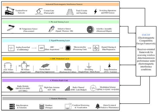
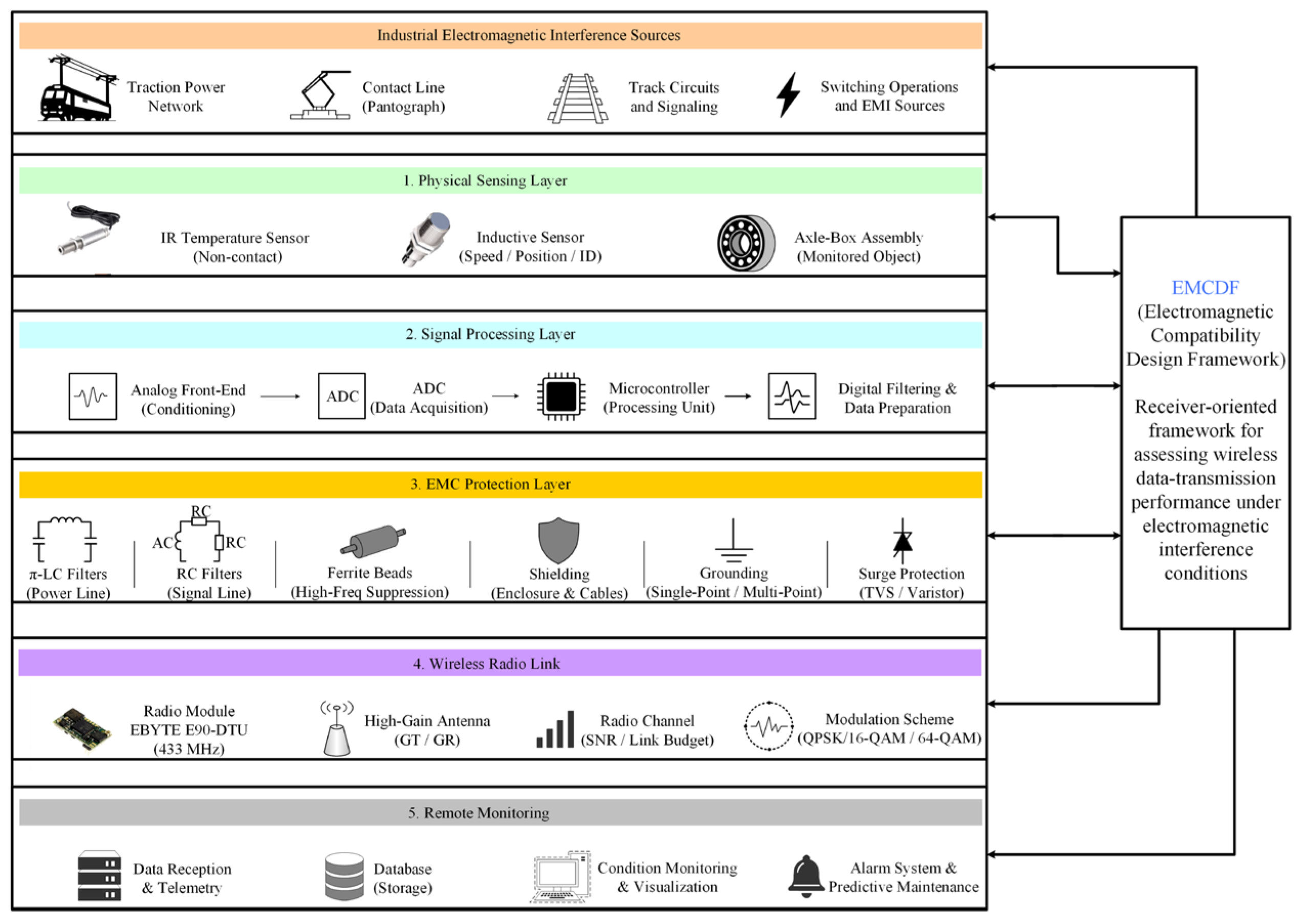
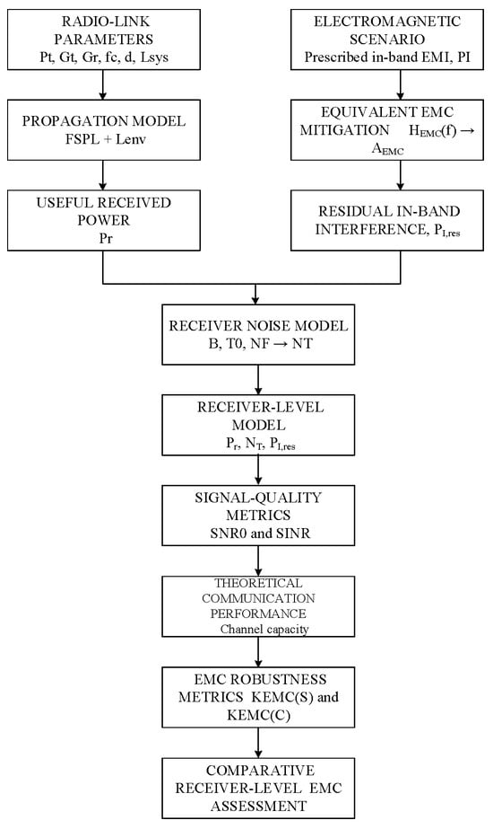
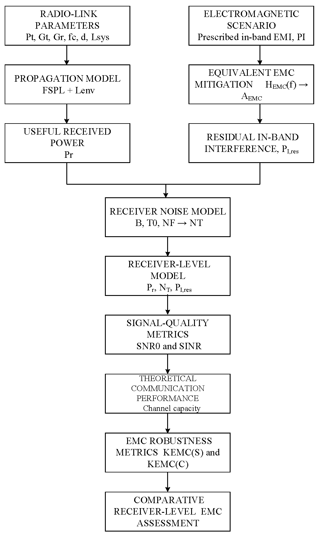
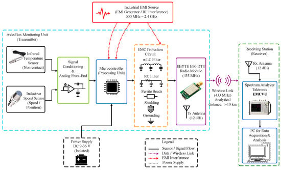
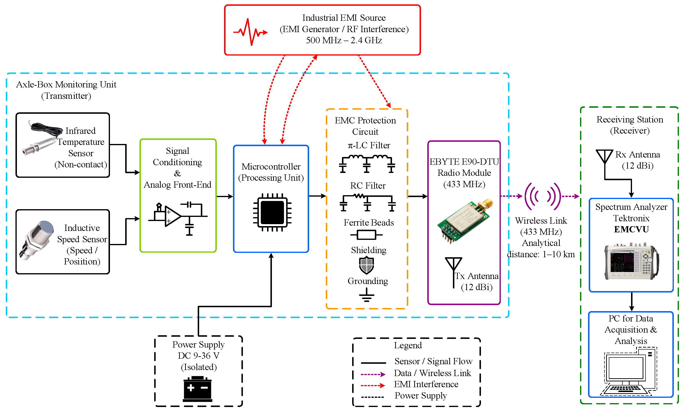
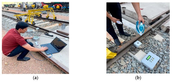
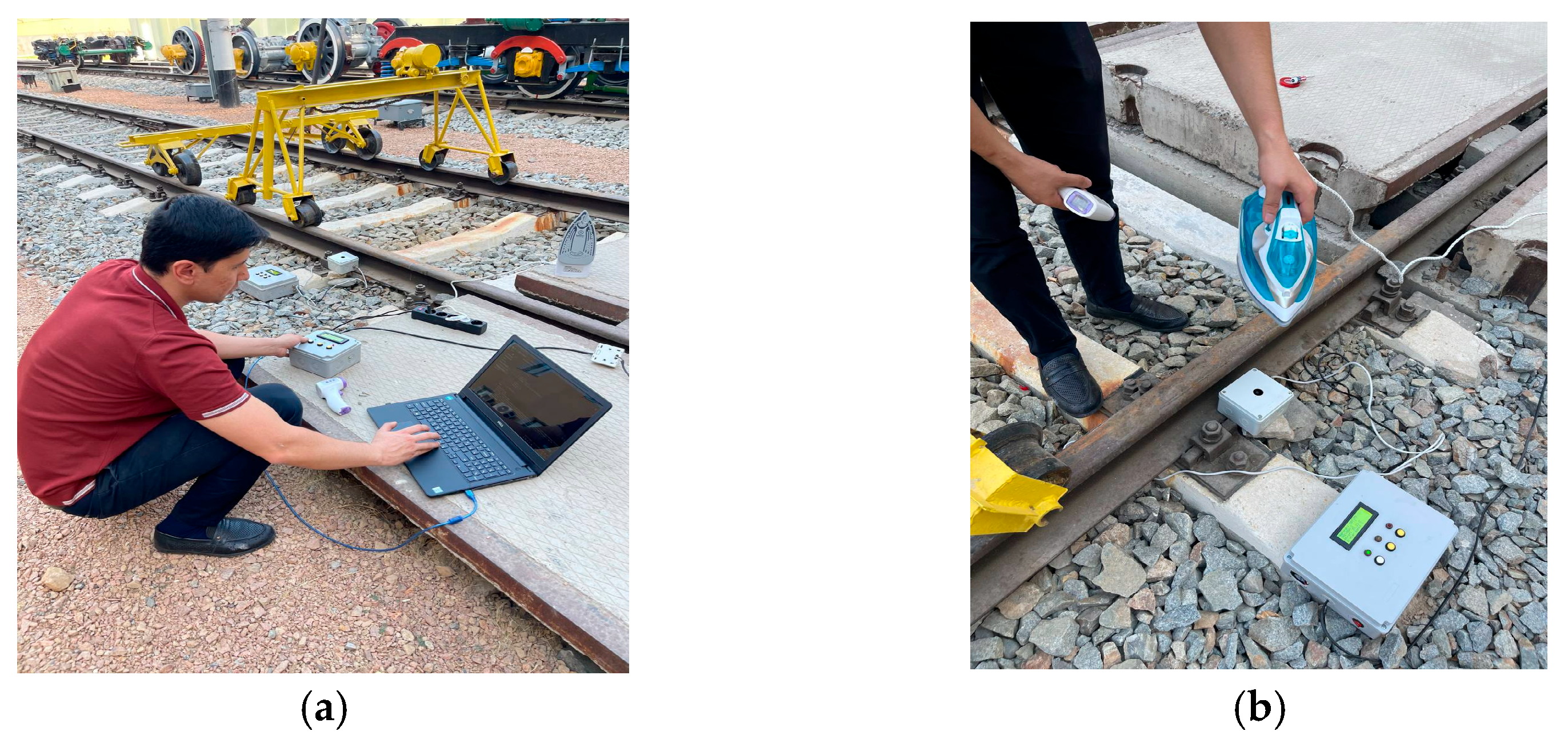
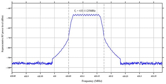
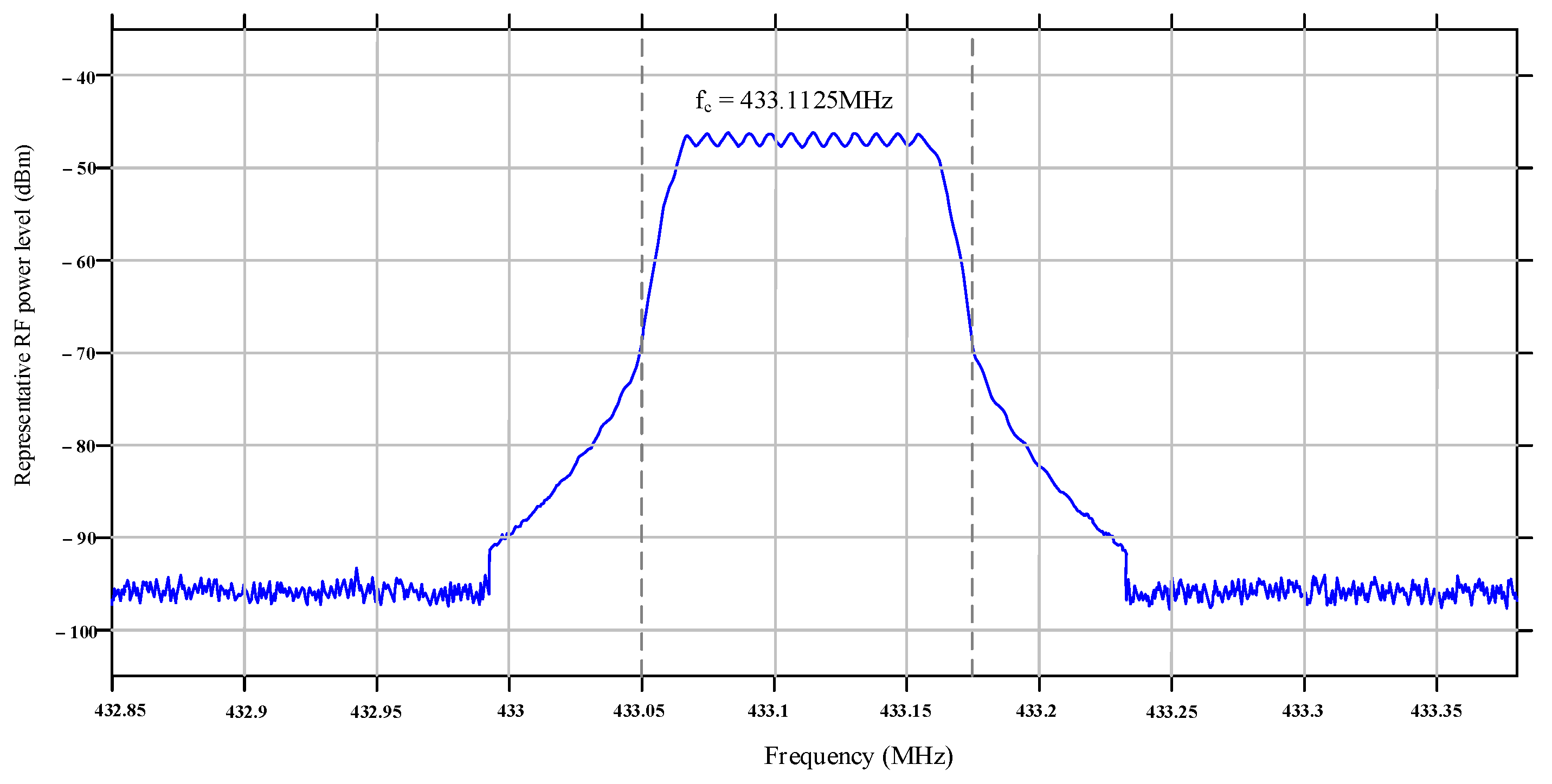
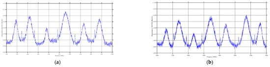
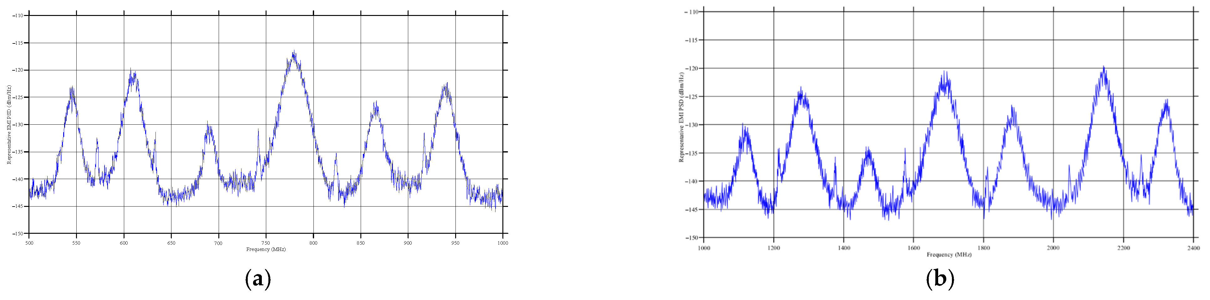
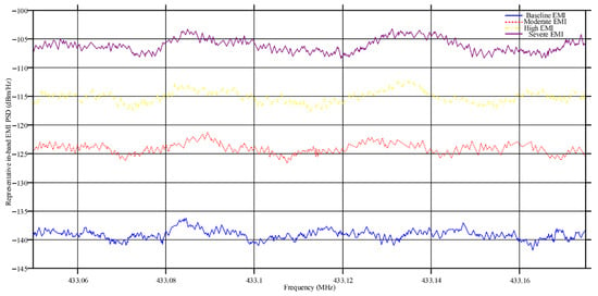
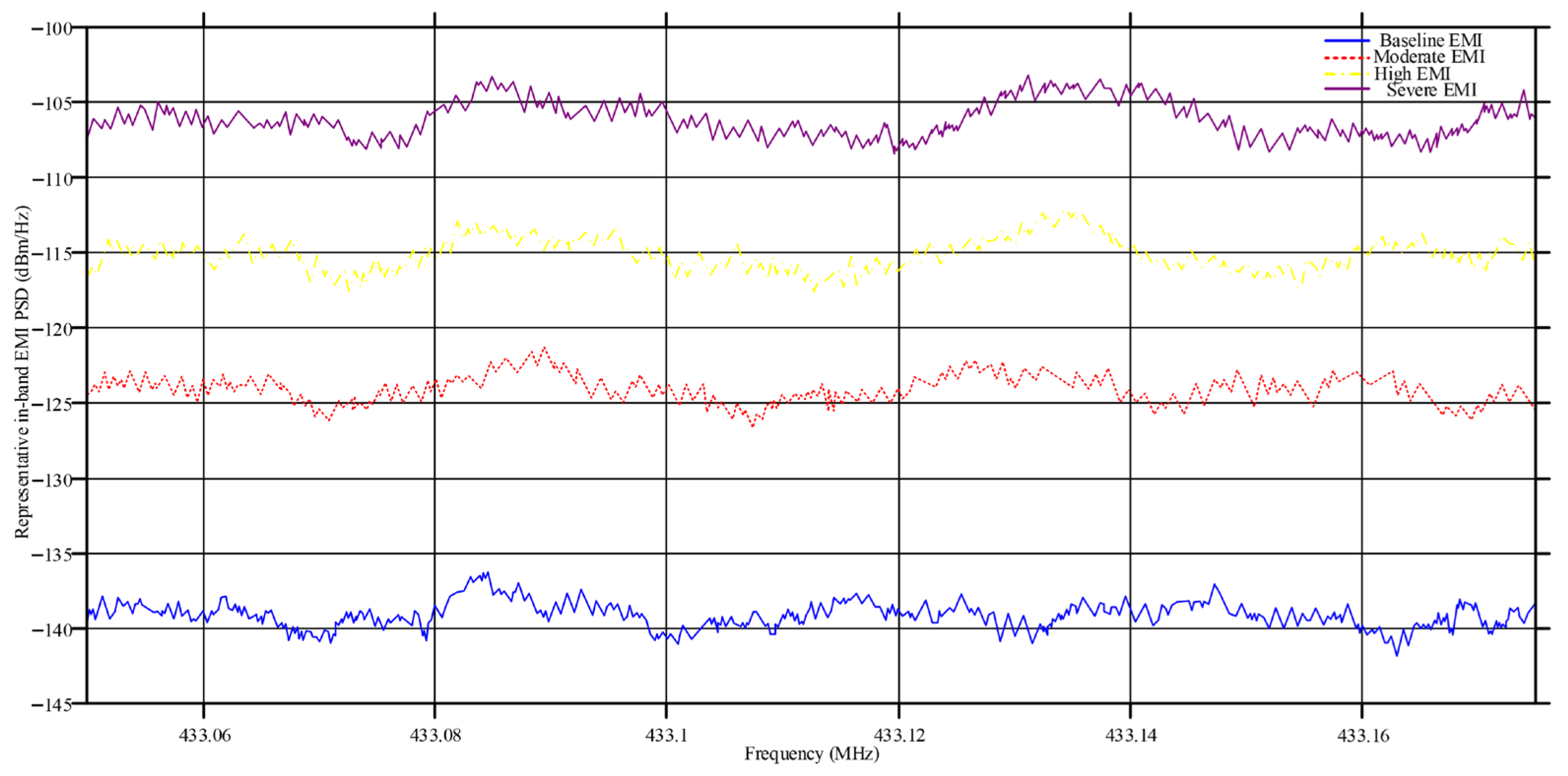
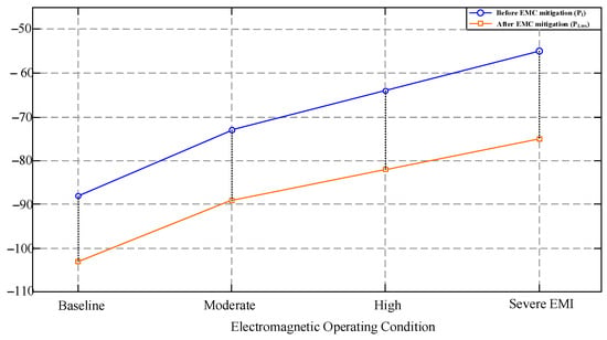
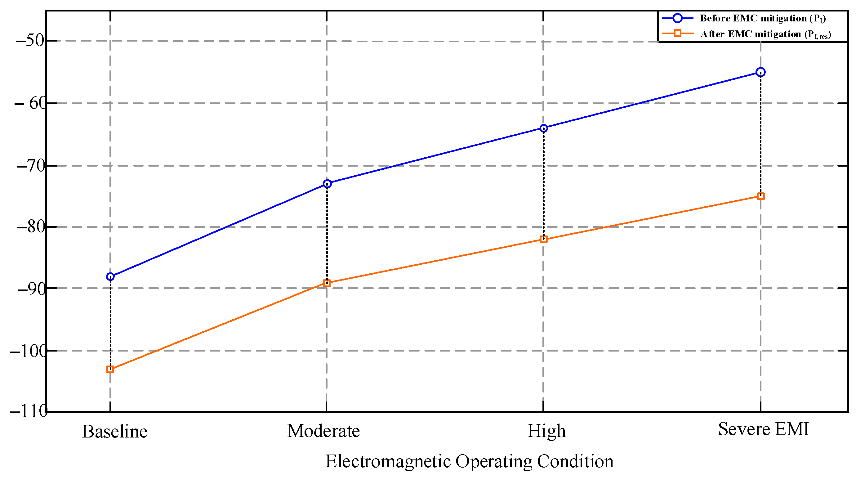
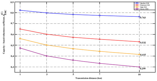
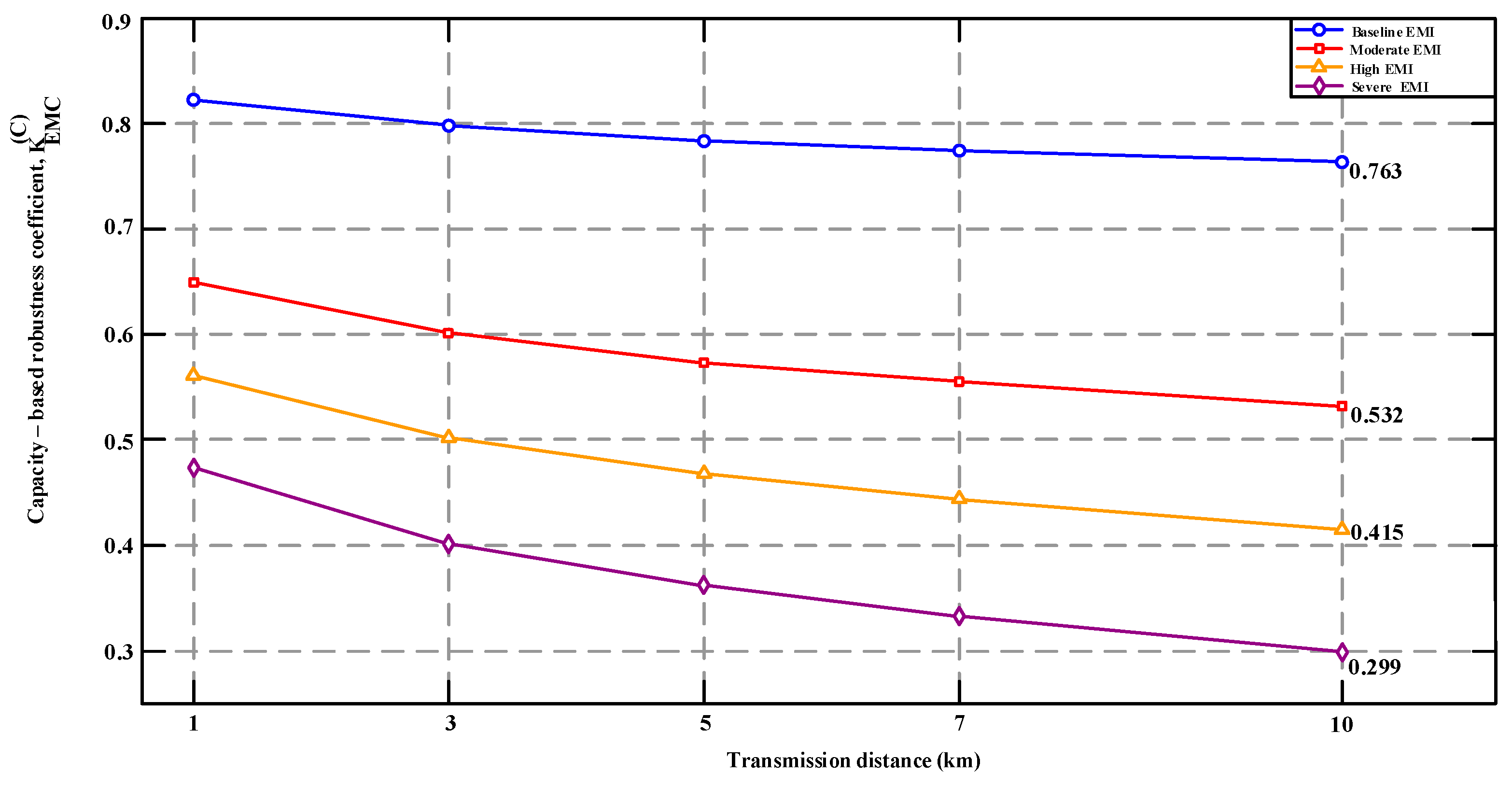

Disclaimer/Publisher’s Note: The statements, opinions and data contained in all publications are solely those of the individual author(s) and contributor(s) and not of MDPI and/or the editor(s). MDPI and/or the editor(s) disclaim responsibility for any injury to people or property resulting from any ideas, methods, instructions or products referred to in the content. |
© 2026 by the authors. Licensee MDPI, Basel, Switzerland. This article is an open access article distributed under the terms and conditions of the Creative Commons Attribution (CC BY) license.