


Abstract
Stabilisation of autonomous vehicle platoons becomes challenging in the presence of uncertain delays in actuator dynamics and vehicle-to-vehicle communication. This paper presents a distributed fractional-order proportional derivative (FOPD) control protocol for a platoon operating under various communication topologies, with bounded uncertainties in actuator lag and communication delay, respectively. It builds on an auxiliary function-based robust stability approach that provides a geometric interpretation of the delay-uncertain characteristic family and eliminates the need for exhaustive parameter gridding. This is followed by a numerical design procedure that evaluates the derived robust stability conditions on explicitly stated frequency grids. Numerical analysis of heterogeneous platoons indicates that the FOPD strategy produces bounded stable responses for the sampled uncertainty realisations and exhibits improved tracking behaviour compared with the integer-order PD baseline using the same numerical values of and . It also provides better damping of oscillations and reduced tracking errors under uncertain operating conditions.
1. Introduction
An autonomous vehicle platoon is a collaborative driving scenario in which a string of autonomous vehicles (CAVs) move in a coordinated manner and maintain the required inter-vehicular spacing. They communicate wirelessly via a vehicle-to-vehicle (V2V) network. The rest of the platoon’s vehicles, except the lead vehicle, are referred to as followers, while the lead vehicle is known as the leader [1,2]. Depending on the information transmitted by the neighbouring vehicles, the followers adjust their states, i.e., speed and acceleration, in order to achieve the platoon formation. This coordination act has been viewed in the light of the synchronisation and consensus theory of multi-agent systems, where agents share local information and synchronise their actions to meet a shared objective [3]. Recent multi-agent studies have further established consensus tracking conditions over asynchronous cooperation–competition networks [4] and characterised the convergence rate of leader–follower consensus under communication delays through products of substochastic matrices [5].
The formation of the platoon is governed by a four-component framework. They consist of (i) node dynamics (ND), which is the longitudinal vehicle model of the followers; (ii) information flow topology (IFT), also known as modelling of the communication network; (iii) formation geometry (FG), also known as spacing policy, i.e., policy which governs the desired intervehicular distance within vehicles of the platoon; and (iv) distributed controllers (DC), which calculate the local control action based on shared information in order to bring platoon formation. Readers can find more information on the four-component framework in [6,7,8]. Vehicle platooning offers several benefits. Some of them are reduced energy consumption due to aerodynamic drag reduction, improved road capacity, and increased passenger comfort due to coordinated braking and acceleration [9,10,11].
Despite these advantages, vehicle platooning is still constrained by several challenges. One of the prominent issues is the delays. These delays can affect system stability and performance to the point of instability or even collisions [12]. In addition, control measures must be developed not only to provide the maximum delay that can be tolerated to maintain platoon stability, but also to provide robustness to changes in delays. The authors of [13] investigated the effects of communication delays in a platoon system and used the cluster treatment of characteristic roots (CTCR) framework to characterise the regions of parametric stability under delay. They also incorporated an acceleration feed-forward system to enhance stability and robustness. In the case of both model uncertainties and delays, the scholars in [14] proposed a robust min–max model-predictive control approach. They optimised platoon behaviour using worst-case model realisations and actuator lag variations. To eliminate non-ideal delays in V2V communication, the work in [15] proposed a state predictor-based control scheme that compensates for communication delays by transmitting future information. They found that the maximum tolerable delay is determined by the maximum eigenvalue of the communication network. In addressing similar problems in the presence of multiple time-varying communication delays and disturbances, the authors in [16] proposed a distributed adaptive protocol. It used a Lyapunov-Krasovskii Functional (LKF) to obtain delay-dependent Linear Matrix Inequalities (LMIs) that guaranteed robust synchronisation of the platoon. Additionally, in another work [17], the Lyapunov stability method was used to develop a distributed adaptive robust control scheme to compensate for communication time delays. They provided a low-dimensional linear matrix inequality (LMI) condition for platoon length-independent stability. Subsequently, the work in [18] designed an event-based, adaptive, robust model-predictive control (RMPC) and found the necessary conditions for asymptotic stability in the presence of time delays. Similarly, in [19], the authors addressed several issues arising from varying communication delays and uncertain parameters by designing robust proportional integral derivative (PID) controllers. They implemented LKF to derive the robust stability conditions of the platoon. Recent advances in robust stability include parameter-space approaches proposed in [20], which parametrise feasible sets of control parameters to ensure robust stability in the event of communication delays. Also, the work in [21] presented a safety-critical control architecture (based on predictor feedback with adjustable control barrier functions) that demonstrated robust stability despite multiple actuator and communication delays. A V2X-assisted distributed computing and cooperative-control framework has also been developed for CAV ramp merging by combining distributed trajectory planning with iterative model-predictive control [22].
These studies motivate the selection of a controller whose stability can be certified over bounded delay intervals. In fractional-order control systems, fractional-order controllers (FOCs) have been widely used to increase robustness against uncertainties in standalone (single-agent) systems [23,24,25,26,27,28]. Fractional-order control is a generalisation of the conventional integer-order control in which non-integer integration or differentiation (or both) operators are modified by replacing the principles of the standard calculus with the principles of the fractional calculus. This mathematical extension provides the control loop with additional degrees of freedom, enabling the fractional-order integral or derivative to achieve more precise frequency-response tuning. Consequently, due to the iso-damping property of FOC, the overshoot of the closed-loop system becomes nearly invariant with respect to gain variations caused by uncertainties [29,30,31,32]. Within the FOC framework, several conventional integer-order (IO) controllers have been converted into their respective FOCs. The algorithm adopted in this work is the fractional-order proportional derivative (FOPD). The FOPD controller contains a fractional-order derivative whose derivative order is in the interval . This, in turn, exhibits the effect of the derivative, which is flexible and adjustable to the desired performance. Compared to traditional proportional derivative (PD) controllers, the FOPD has better high-frequency noise attenuation and a wider stability margin [30].
In vehicle platooning, distributed fractional-order control (DFOC) is still at a relatively early stage of development. Early work, including [33], suggested a DFOC for the platoon in which vehicles communicate using a predecessor-following (PF) topology, where each vehicle communicates with its immediate predecessor. They dealt with the issue of system uncertainties. Further research has been dedicated to the iso-damping behaviour of DFOCs, e.g., in [34]. In [35], the authors used DFOC to discuss the issue of communication delays. However, both publications, i.e., [34,35], focused solely on the calculation of control laws for vehicles communicating in a PF topology. Other more recent studies have applied the DFOC development to enhance platoon resilience to cyberattacks [36] but have made their results applicable only to bidirectional (BD) communication, i.e., to-and-fro communication between vehicles and their immediate predecessor and successor vehicles, respectively. In a more recent contribution, authors in [37] demonstrated the design of an adaptive DFOC of a vehicle with a PF topology.
The authors are aware of the study in [38], which developed distributed fractional-order controllers applicable to several communication topologies. To the best of the authors’ knowledge, existing studies have not reported a robust stability framework for distributed FOPD vehicle platoons that concurrently treats interval actuator lag and communication-delay uncertainties across multiple information flow topologies. Neither the auxiliary function argument nor the zero-exclusion principle is claimed as new individually. The specific contribution is their integration with a finite-frequency value set construction and eigenvalue clustering for this uncertain distributed FOPD platoon problem.
This paper closes the gap by extending the framework of [38] to the robust setting, where bounded uncertainties in actuator and communication delays are addressed concurrently. The main contributions are as follows:
- (i)
- A closed-loop stability analysis framework is developed for distributed FOPD-controlled vehicle platoons with uncertainties in actuator lag and communication delay . The analysis takes into account both the presence of distinct and repeated positive real eigenvalues of the communication information matrix . This further includes the eigenvalue clustering effect by considering the neighbouring eigenvalues of through one or more intervals and hence an additional uncertainty interval, giving a trade-off between conservatism and computational effort. The resulting framework combines an auxiliary function nominal-stability test, the zero-exclusion principle, a finite-frequency geometric value set enclosure, and eigenvalue clustering to treat the simultaneous delay intervals without exhaustive gridding of the uncertain parameters.
- (ii)
- An optimisation-based tuning procedure is formulated to determine numerically feasible controller parameters. Violations of the sampled robust stability inequalities are encoded in a nonnegative hinge penalty objective. A zero penalty indicates satisfaction of the prescribed positive margin on the selected frequency grids; it does not constitute a validated continuous-frequency numerical certificate.
- (iii)
- Numerical simulations are performed on vehicle platoons with nonlinear longitudinal dynamics to evaluate the closed-loop behaviour of the designed FOPD controller under the tested operating conditions. Communication topologies of different nature are used, and comparisons are made against an integer-order PD baseline using the same numerical values of and in both nominal and uncertain conditions.
The stability result in this paper concerns internal robust stability of the closed-loop platoon. It does not establish string stability or bound disturbance amplification along the vehicle string; those properties are outside the present scope and are identified as future work.
The remainder of the paper is organised as follows. Section 2 introduces the preliminaries about the information flow graph, the dynamics of the vehicle system, assumptions about the delays, modal coordinate form, and fractional calculus preliminaries. Section 3 states the problem of interest and formulates the distributed FOPD control strategy. Section 4 analyses the closed-loop system dynamics, and the characteristic equation of the mode is derived; subsequently, the interval characteristic equation is developed in the presence of the actuator and communication delays. Section 5 develops the robust stability criteria based on the auxiliary function formulation, finite-frequency stability condition, zero-exclusion theorem, and eigenvalue clustering framework. Section 6 describes the procedure for selecting the FOPD controller parameters via an optimisation technique. Section 7 includes proofs of the developed robust stability theorems. Section 8 demonstrates the validity of the proposed approach numerically, i.e., using the FOPD tuning procedure, analysing the robust stability in the frequency domain and sampled-time simulations and comparing the performance of the designed FOPD controller with that of the traditional integer-order PD controller under nominal and uncertain conditions. Section 9 concludes the paper. Appendix A studies the robust stability for the case where there exist repeated positive real eigenvalues of the information matrix.
2. Background
This section provides an overview of the background of this paper, including the network topology, vehicle dynamics, delay assumptions, modal coordinate notation, and the mathematical preliminaries used in the stability analysis.
2.1. Network Model
Consider a network of N follower vehicles represented by the graph , where is the set of vehicles and represents the communication links. An edge means that vehicle i receives information from vehicle j. The network is described by the adjacency matrix , where if and otherwise. The Laplacian matrix is defined by
or equivalently, , where the in-degree matrix has entries . The connection between the leader and the followers is modelled by the pinning matrix , where if the leader is connected to vehicle i (i.e., if the edge exists), and otherwise. From the literature [8,39], the information matrix is defined as .
Assumption 1.
Let the communication topology be represented by the information matrix . The following conditions are assumed:
- (a)
- The network graph contains a spanning tree rooted at the leader vehicle, so that the leader information is available, directly or indirectly, to all N follower vehicles.
- (b)
- The information matrix has distinct, real, and strictly positive eigenvalues . Each eigenvalue has algebraic multiplicity , satisfying
Assumption 2.
The communication delay is homogeneous across all communication links. Hence, the controller uses delayed spacing information evaluated at , while the control input is denoted by . The actuator time constant τ and the communication delay ϕ are both uncertain but bounded such that
Assumption 2 covers a fixed information flow topology and an unknown but constant homogeneous communication delay within the stated interval. It does not provide a guarantee for packet loss, link-dependent time-varying latency, or switching topologies. In those cases, the fixed modal decomposition and the associated characteristic family would have to be replaced by a stochastic or switched-system analysis. Random packet loss and Markovian switching topologies have, for example, been treated using dedicated frameworks in [39,40]. Extending the present FOPD protocol to these non-ideal communication mechanisms is left for future work.
2.2. Vehicle Model and Modal Representation
2.2.1. Longitudinal Vehicle Dynamics
A linearised third-order model of the longitudinal motion of each follower is widely used in the platooning literature [8,41]:
where , , and denote the position, velocity, and acceleration of the follower vehicle, respectively, and is the corresponding control input. The leader trajectory is treated as an exogenous reference signal, while the third-order model in (4) applies to the follower vehicles . Practically, nonlinear effects on vehicle longitudinal dynamics include tyre–road contact, aerodynamic forces, compliance of the suspension, longitudinal slip, and friction that is time-varying [42]. Additional complexity can be caused by tyre force hysteresis and the interaction between lateral and longitudinal motion [43,44]. However, locally linearised models can still be used in controller design, as they retain the dominant longitudinal behaviour and are less computationally intensive. Accordingly, the analytical certificate developed below applies to the linearised error model and is a local internal stability result, not a global nonlinear stability guarantee. Its use for the nonlinear plant is restricted to operating regimes in which the linearised model retains the dominant longitudinal behaviour and the neglected effects remain within the tested parameter variations. The numerical study therefore supplements the analysis by using nonlinear longitudinal dynamics with explicit variations in vehicle mass, aerodynamic drag, rolling resistance, wheel radius, transmission efficiency, and actuator lag. The leader acceleration is added to the follower dynamics via the vector:
Assumption 3.
For the robust stability derivation, the leader acceleration is treated as an exogenous input, and the characteristic equation is obtained from the homogeneous error dynamics. The leader acceleration is assumed to be piecewise constant, so that
within each manoeuvre phase. During an interval of nonzero constant , the stable closed loop may exhibit a bounded spacing offset; exact asymptotic convergence is asserted for manoeuvres satisfying , as in the numerical cases considered in this paper.
2.2.2. Modal Coordinate Representation
For the subsequent stability analysis, the velocity error vector is expressed in modal coordinates. Using the decomposition given in (3), the transformed error vector is defined as
The partitioning is taken with respect to the m distinct eigenvalues of . For each , the corresponding modal blocks are written as
with for . The same transformation is applied to the leader acceleration vector , yielding
where each block is given by
and denotes the q-th modal component of the leader acceleration. Its Laplace transform is
For the case of constant leader acceleration, this becomes
where denotes the corresponding constant-amplitude vector.
2.3. Mathematical Preliminaries
For the fractional-order terms used later in the distributed control law, the operator is interpreted in the transfer-function sense under admissible zero initial conditions. Hence, for a signal with Laplace transform ,
where .
The robust stability analysis developed later uses two standard tools from complex analysis and robust control theory. These tools are recalled here for completeness.
Principle of Argument Theorem [45]:
Let be analytic inside a simple closed Jordan curve Γ, continuous on Γ, and nonzero on Γ. If K is the image of Γ under , then the number of zeros of inside Γ, counted with multiplicity, is
Equivalently, p is the winding number of K around the origin.
Zero-Exclusion Principle [46,47,48]:
An interval family of characteristic functions is robustly stable if it contains at least one stable member and the origin is excluded from its value set for all frequencies, i.e., for .
3. Control Objective and Distributed FOPD Strategy
This section states the platoon control objective and introduces the distributed FOPD control law used in the robust stability analysis.
3.1. Control Objective
The platoon control problem is to design a robust control strategy that ensures (i). Synchronising vehicle states over diverse network topologies and (ii). Maintaining the prescribed intervehicular spacing despite uncertainty in the actuator delays () and the communication delays (). For the third-order vehicle dynamics given in (4a)–(4c), the control objectives are expressed as
where denotes the desired constant spacing between the and vehicles, and denotes the desired spacing between the follower and the leader. The spacing constants are assumed geometrically consistent, i.e., , so that . Defining the state mismatches as
The synchronisation objective is to ensure that the mismatch vectors converge to the origin in the presence of uncertain delays
where , , and denote the vectors of state mismatches for all follower vehicles .
3.2. Distributed Control Law
The distributed fractional-order control law used for the follower dynamics is formulated through the information matrix and explicitly accounts for the communication delay , which is computed as
where and denote the proportional and derivative gains, respectively, and denotes the fractional operator of order , interpreted according to the operator convention introduced in Section 2. Using the property , the lumped control input for FOPD becomes
4. Closed-Loop Dynamics and Interval Characteristic Equations
This section derives the closed-loop error dynamics, obtains the modal characteristic equation, and defines the interval characteristic family used in the robust stability analysis.
4.1. Closed-Loop Error Dynamics
Consider the third-order vehicle dynamics in (4). By reformulating the dynamics and using with , the open-loop velocity error dynamics can be expressed as
where is the broadcast leader acceleration vector in (5), acting channel-wise, and by Assumption 3. The lumped FOPD control law in (17) is designed based on spacing error. Using the kinematic relation and standard fractional calculus Laplace properties under admissible initial conditions, the control law can be equivalently expressed in the velocity domain as
where . Substituting (19) into (18) yields the closed-loop system
4.2. Decoupling and Laplace Transform
Applying the modal transformation , the modal error definition in (6a) and premultiplying (20) by gives the dynamics in modal coordinates
where from (8a).
Taking Laplace transforms of (21) and using yields
Collecting all terms in on the left-hand side gives
Rearranging gives the master form in terms of the block-diagonal structure discussed in Lemma A1 (see Appendix A):
with
and
For stability analysis, the characteristic equation is obtained from the homogeneous part, equivalently by . Multiplying (25) by yields the polynomial-form characteristic matrix
From Lemma A1 in Appendix A, after grouping all Jordan blocks associated with the same eigenvalue , the corresponding modal block can be written as , where is nilpotent. Hence, stability is determined by the i-th diagonal block
The characteristic polynomials are
Each modal block satisfies , and asymptotic stability depends only on the roots of for all , given in (29).
4.3. Interval Closed Loop Characteristic Equations
To design a robust controller, it is assumed that the time constant and the time delay are subject to interval uncertainties, satisfying the constraints and . Thus, applying the FOPD controller to the system defines the family of interval fractional-order equations as in Equation (31).
where , , , and denotes the vector of real uncertain parameters. The fractional power is evaluated on the principal branch; therefore, for ,
The set Q denotes the uncertainty bounding set.
5. Main Results
The distinct positive eigenvalues of the information matrix are ordered as
For computational purposes, these eigenvalues may be partitioned into M nonempty clusters , , where . Each cluster is represented by the interval , where and . No fixed eigenvalue separation threshold is required by the proposed robust stability framework. The clustering is a user-selected computational partition; once a cluster is formed, the stability conditions are verified over the complete interval . Hence, the choice of M provides a trade-off between computational effort and conservatism: increasing M produces narrower eigenvalue intervals and generally reduces conservatism, whereas decreasing M reduces the number of interval families at the expense of wider and potentially more conservative eigenvalue bounds. Accordingly, a new family of interval fractional-order equations, denoted as , is defined as follows:
where with , and such that .
In accordance with the zero-exclusion principle stated in Section 2.3, it is necessary to analyse the relationship between the origin and the value set of any interval characteristic function for . The stability of each member must be verified. Therefore, the primary objective is to establish a stability condition for a nominal member of the family . The detailed proofs of the theorems, lemmas, and propositions presented in this section are provided in Section 7.
Theorem 1.
Assume that and that a nominal function within the family is denoted as , given by
where , , and . The functions for in (33) are stable if there exist finite values such that the inequality holds within the frequency range . The expressions for and are defined as follows:
in which
The following lemma restricts the frequency range required for the zero-exclusion test to a finite interval.
Lemma 1.
Assume that . The zero-exclusion condition holds for , where is defined as
Lemma 1 demonstrates that the zero-exclusion condition only needs to be verified over the finite frequency interval .
The quantity represents a critical frequency associated with the interval time delay. This arises because the delay term , with , generates a circular arc in the complex plane whose angular span increases with frequency.
As a result, two distinct scenarios emerge depending on whether the delay-induced arc completes a full rotation within the frequency range of interest:
- If , the delay term completes a full circular sweep, and both low- and high-frequency behaviours must be considered;
- If , only a partial arc is formed, and the analysis simplifies accordingly.
The subsequent lemma addresses the former scenario, while Proposition 1 addresses the latter.
Lemma 2.
Assume that . The zero-exclusion condition holds for if the following conditions are satisfied:
- The value sets and do not overlap in the complex plane for . These sets are defined as
- The inequality holds for all , where is formulated aswith representing the set of exposed edges defined asThe bounding functions are and , and the function denotes the convex combination of complex numbers X and Y:
The complementary low-frequency case is treated next, where the delay-induced value set remains a partial arc over the whole verification interval.
Proposition 1.
Analysing potential overlaps between value sets can be demanding. To resolve this, the subsequent lemma introduces a geometric envelope composed of exposed edges that encloses the delay value set, allowing robust stability to be validated via an auxiliary function.
Lemma 3.
At any fixed frequency , the exact delay-dependent value set is
This set is contained in the closed filled polygonal outer enclosure
where , , and denotes the closed filled polygonal region determined by the cyclically ordered vertices. Therefore,
where the vertices are sequenced as
with the upper and lower boundary vertices generated by
Here, the discretisation parameter is an integer such that .
The preceding developments provide the essential ingredients for robust stability analysis, namely nominal stability, finite-frequency verification, and geometric separation of value sets. Nevertheless, a unified formulation that combines these conditions into a single, implementable robust stability criterion has not yet been explicitly stated. The following theorem and proposition bridge this gap by combining these results into a comprehensive and computationally tractable framework. Specifically, they provide sufficient conditions that guarantee both nominal stability and zero-exclusion across the full frequency domain, covering both parametric scenarios and .
Theorem 2.
Assume that . The family is robustly stable if the following geometric conditions hold:
- There exist finite values such that is satisfied for , where and are defined in Theorem 1.
- For the low-frequency range, define the actuator uncertainty segment asFor every eigenvalue cluster, define the complete pointwise separation margin asSince both sets are compact,Therefore, this condition excludes boundary contact, proper segment crossing, and partial or complete containment. Moreover, the function is the high-frequency bound defined in (42). The vertices are explicitly defined aswithand
The remaining case corresponds to the partial delay arc regime, for which the robust stability test reduces to the lower-frequency geometric condition.
Proposition 2.
Assume that the frequency bounds satisfy . The family remains robustly stable if the following criteria are met:
- There exist finite positive values ensuring is held within , following the definitions of and established in Theorem 1.
- There exists a discretisation such that the lower-bound inequality holds throughout .
Remark 1.
The condition is a complete pointwise segment–filled-polygon separation condition. Unlike tests involving only selected vertices or endpoints, it also detects a proper interior–interior crossing and partial or complete containment. In the numerical implementation, segment–polygon boundary intersections and endpoint-in-polygon containment are tested first. If the sets are disjoint, is obtained from the minimum distance between the actuator segment and all polygon edges. Theorem 2 requires this distance to remain positive for every frequency in the stated continuous interval; evaluation on a finite grid provides sampled numerical evidence only.
6. Tuning of FOPD Gains
This section presents the tuning procedure for the distributed FOPD controller and its robust stability validation. The design is explicitly aligned with the robust stability conditions developed in Section 5. The following optimisation problem provides a numerical controller-design procedure based on the robust stability conditions derived above. Equation (47) uses a nonnegative hinge penalty to measure violations of a prescribed sampled positivity margin. At each sampled frequency, a penalty is incurred whenever the corresponding stability-function value falls below . A zero penalty therefore indicates sampled feasibility. The objective does not continue to maximise the stability margin after all sampled values exceed .
For numerical implementation, the continuous frequency interval is evaluated on a finite grid. This discretization is used only to compute the stability-testing functions during the optimization and does not modify the continuous-frequency formulation of the theoretical results. A sufficiently dense frequency grid is employed to approximate the minimum over the prescribed interval. The constrained nonlinear optimization is solved using fmincon; however, the proposed stability conditions are independent of this particular solver, and other suitable constrained nonlinear optimization algorithms may also be used.
The controller parameters are obtained by solving an optimisation problem over the vector
while the auxiliary constants used in the nominal-stability test are selected a priori. The objective is to penalise violations of the sampled robust stability inequalities for the interval family . Let
and let , , and denote the sampled grids for the nominal, low-frequency, and high-frequency conditions, respectively. The sampled hinge penalty is
Here,
and when . Otherwise, . The constant is the prescribed sampled positivity margin.
The nonlinear optimisation problem is solved using the fmincon solver, starting from an initial guess and subject to the bounds
with the additional constraint . The auxiliary constants are fixed before the optimisation. Numerical feasibility on the selected grids is declared when the returned penalty is zero within the solver tolerances and all sampled minimum values exceed the prescribed margin .
The resulting controller-design problem is solved numerically using MATLAB’s fmincon. The parameter bounds and the condition are imposed directly as optimisation constraints. The sampled robust stability inequalities are encoded in the penalty objective rather than imposed as separate nonlinear constraints. A candidate controller is treated as numerically feasible only when the returned penalty is zero within the solver tolerances and all reported sampled minima exceed the prescribed margin .
The optimisation problem is nonlinear and is not assumed to be globally convex. Consequently, the obtained feasible solution may depend on the initial guess, and no claim of global optimality or independence from initialisation is made.
The inequalities in Theorem 2 and Proposition 2 are continuous-frequency conditions. Equation (47), by contrast, is a sampled numerical approximation: a zero penalty on the finite grids , , and cannot by itself exclude a narrow zero crossing between adjacent samples. Accordingly, the theoretical result is rigorous when its inequalities hold for every frequency in the stated intervals, whereas the numerical study in Section 8 is explicitly reported as sampled numerical evidence rather than as a validated continuous-frequency certificate.
The tuning procedure is summarised as follows.
Step 1. Order the distinct positive eigenvalues , , and select a partition into M nonempty clusters according to the desired trade-off between computational effort and conservatism. For each cluster , define from its minimum and maximum eigenvalues.
Step 2. Compute from Theorem 1, from Lemma 1, and the critical frequency .
Step 3. Select the appropriate robust stability condition:
- If , apply Theorem 2.
- Otherwise, apply Proposition 2.
Step 4. Solve the optimisation problem using (47) over the specified frequency range to obtain a numerically feasible set of controller parameters , , and , for the selected auxiliary constants .
Remark 2.
As discussed in Section 5, the clustering of eigenvalues in the interval family introduces a trade-off between computational complexity and conservatism in the robust stability analysis. Increasing the number of clusters reduces conservatism by tightening the bounds on the eigenvalue-dependent characteristic equations, at the expense of higher computational cost. Conversely, reducing the number of clusters simplifies the analysis but introduces conservatism, as a wider eigenvalue interval must be considered within a single characteristic family. In the limiting case , the clustered interval system reduces to
where , with
In this case, the entire spectral variation of the information matrix is embedded into a single interval, which reduces the computational burden but may lead to conservative stability conditions due to overbounding of the value sets in the complex plane.
7. Proofs of the Main Results
This section provides the detailed proofs of the main theoretical statements presented in Section 5. The derivations establish the nominal stability conditions, finite-frequency bounds, zero-exclusion properties, and the geometric separation conditions used in the robust stability analysis of the interval fractional-order platoon system.
Proof of Theorem 1
According to the Principle of Argument, is stable if the auxiliary function
exhibits no encirclement of the origin in the complex plane for . Substituting yields
where is defined in (35), and the imaginary component is derived as
Given that , the condition implies . Consequently, does not cross or encircle the origin, confirming that is stable.
Proof of Lemma 1:
If , then . For frequencies , applying the triangle inequality yields
Consequently, the inequality
ensures that , establishing that the zero-exclusion condition holds for . □
Proof of Lemma 2.
For any fixed frequency
an admissible zero of the characteristic family exists if and only if the two component value sets intersect
Indeed, an intersection provides admissible values of , , and for which the two component terms cancel in the characteristic equation. Consequently, the first hypothesis of the lemma, which requires these value sets to remain disjoint, establishes zero exclusion throughout this frequency interval. For the upper frequency range , the delay term generates a full circular trajectory in the complex plane due to the interval uncertainty in . The condition ensures that the minimum distance between the polynomial term and the delay-dependent term remains strictly positive. Hence, the intersection is avoided, and the zero-exclusion condition is satisfied over the entire frequency domain. □
Proof of Proposition 1.
The proof follows directly from Lemma 2. □
Proof of Lemma 3.
For a fixed frequency , the continuous value set defined by possesses a boundary formed by two straight radial segments:
along with two arcs connecting the respective vertices and . The largest bounding arc corresponds directly to the upper vertices . By defining a representative sector with an angular width of
this sector is bounded by and . Evaluating the right triangle geometric relation
The intermediate vertex is obtained as
By repeating this construction across all sectors, it is demonstrated that the largest continuous arc is fully enclosed by the sequence of consecutive edges . Concurrently, the lower boundary is bounded by the edges bridging . Aggregating all such edges accurately yields the polygonal envelope described in (43), thereby confirming that the value set of is entirely confined within . □
Proof of Theorem 2.
The proof is established by explicitly verifying the two conditions required by the zero-exclusion principle for each characteristic family , .
First, consider the existence of a stable member. By the first condition of Theorem 2, there exist finite constants such that
Hence, by Theorem 1, the selected nominal characteristic function is stable for every . Therefore, each family contains at least one stable member.
It remains to verify the zero-exclusion condition over the whole frequency axis. From (32), for a fixed frequency ,
Using the component value sets defined in (40) and (41), a zero of the characteristic family exists at if and only if there exist admissible values of , , and such that
Equivalently,
Therefore, the zero-exclusion condition can be established by proving that and are disjoint for every .
Consider first the low-frequency interval
By Lemma 3, the exact delay-dependent value set satisfies
For a fixed frequency, the polynomial value set is the complete actuator uncertainty segment
The second condition of Theorem 2 requires
Consequently,
Because the two sets in the definition of are compact, strict positivity of their distance implies
Using the outer-enclosure property, it follows that
Therefore,
throughout the low-frequency interval. At , the same set-distance condition is interpreted through the closed, possibly degenerate, polygonal limit.
Next, consider the higher-frequency interval
In this range, the angular span generated by the delay uncertainty contains a complete circular sweep. By Lemma 2, the condition
with defined in (42), guarantees strict separation between the polynomial value set and the delay-dependent value set. Therefore,
and consequently
throughout this frequency interval.
Finally, Lemma 1 establishes that
Combining the low-frequency interval, the higher-frequency interval, and the region above yields
Thus, both hypotheses of the zero-exclusion principle are satisfied for every family : Theorem 1 guarantees the existence of at least one stable member, while the preceding geometric arguments establish that the origin is excluded from the characteristic value set for every admissible uncertainty and every . Therefore, every member of is stable. Since this conclusion holds for all , the uncertain closed-loop system is robustly stable. □
Proof of Proposition 2.
The proof follows directly from Theorem 2. Indeed, when the verification interval lies entirely in the low-frequency region. Hence, the high-frequency condition involving is not required, and the robust stability test reduces to the conditions and These conditions ensure nominal stability and zero-exclusion over the entire required frequency range. Therefore, is robustly stable. □
8. Numerical Validation
In this section, validation of the distributed FOPD controller that has been proposed is carried out from two different perspectives. In Section 8.1, the tuning method for FOPD controllers developed in Section 6 is applied to the information flow network considered in this study to evaluate the robust stability inequalities on the stated frequency grids and to provide complementary time-domain evidence for the sampled uncertainty realisations. Section 8.2 contains the performance comparison between the proposed FOPD controller and the integer-order PD controller for the same system in both nominal and uncertain conditions.
8.1. Robust Stability-Based Tuning and Validation of the FOPD Controller
The proposed controller is first evaluated on a platoon with five follower vehicles , with the prescribed intervehicular spacing fixed at m. The actuator lag and communication delay are assumed to satisfy
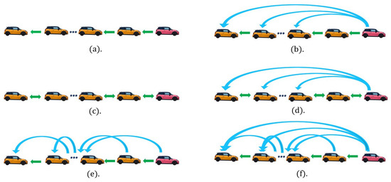
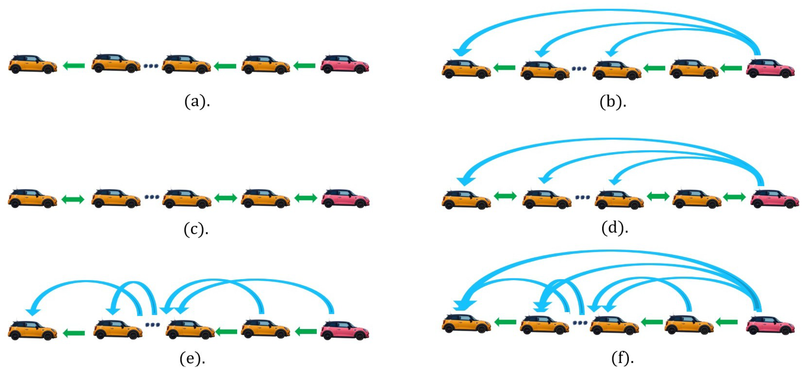
respectively. These ranges are consistent with the actuator lag and V2V communication latency values reported in the literature [49,50,51,52,53]. A common set of uncertainty realisations is generated once in MATLAB after initialising the Mersenne Twister generator with rng(2026,’twister’). The command R_d=rand(100,2) is then used, with s and s. Thus, one homogeneous actuator lag and one homogeneous communication delay are applied to all followers in realisation k, consistently with Assumption 2. The same 100 pairs are reused for every controller and topology. The six information flow topologies considered in the numerical validation are predecessor following (PF), predecessor following with leader (PFL), bidirectional (BD), bidirectional with leader (BDL), two-predecessor following (TPF), and two-predecessor following with leader (TPFL), as shown in Figure 1.
Figure 1.
Common information flow topologies: (a) predecessor following (PF), (b) predecessor following with leader (PFL), (c) bidirectional (BD), (d) bidirectional with leader (BDL), (e) two-predecessor following (TPF), and (f) two-predecessor following with leader (TPFL). Green arrows indicate inter-vehicle communication links, blue arrows indicate leader-to-follower communication links, and the arrowheads indicate the direction of information flow.
The numerical design is now connected directly with the four-step tuning procedure described in Section 6. The purpose is to show explicitly how the eigenvalue grouping, frequency-bound selection, theorem selection, and optimisation stage are used in the numerical implementation.
8.1.1. Step 1. Eigenvalue Grouping
The first step in Section 6 is to group the distinct eigenvalues of the information matrix into interval subsystems. For the six topologies in Figure 1, spectral analysis gives the following eigenvalue sets: for PF, , ; for PFL, and , ; for BD, ; for BDL, ; for TPF, and , ; and for TPFL, , , and , . Hence, all eigenvalues associated with the six information flow topologies lie in the interval . Following Step 1, the eigenvalues are grouped into interval subsystems as
This grouping keeps the isolated largest eigenvalue in a separate cluster, while the remaining eigenvalues are represented by the interval . Therefore, the clustering step reduces the conservatism that would arise if the complete spectral range were treated as a single interval.
8.1.2. Step 2. Frequency-Bound Computation
The second step in Section 6 is to compute the frequency limits required for the nominal and robust stability tests. Since the communication-delay interval is s, the critical frequency associated with the delay uncertainty is
The controller search is carried out using the gain bounds
and the auxiliary constants used in the nominal-stability condition are fixed as
For the two interval subsystems obtained in Step 1, the nominal uncertainty values are selected as
The nominal eigenvalues are and . Using Lemma 1 and Theorem 1, and applying the conservative search bounds and , the frequency limits are obtained as
These limits are calculated from the admissible gain range rather than from only the final optimised gains. Thus, the robust stability verification is performed over a conservative frequency interval.
8.1.3. Step 3. Selection of the Robust Stability Condition
The third step in Section 6 is to select the robust stability condition according to the relation between and . For the present design,
Therefore, the condition required for Theorem 2 is satisfied. Consequently, Theorem 2 is used for the robust stability verification, rather than Proposition 2. This selection also determines the two frequency ranges used for checking , namely rad/s and rad/s.
8.1.4. Step 4. Optimisation of the FOPD Gains
The fourth step in Section 6 is to solve the optimisation problem in (47) over the frequency interval
The complete sampled grids used in the revised computation are
Their maximum spacings are , , and rad/s, respectively. The sampled positivity margin is ; the fmincon constraint, optimality, and step tolerances are , , and , respectively. The penalty function penalises violations of the sampled positivity conditions of the stability functions and over their required sampled frequency ranges. Applying this optimisation step gives the FOPD controller parameters
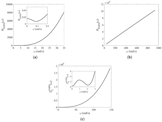
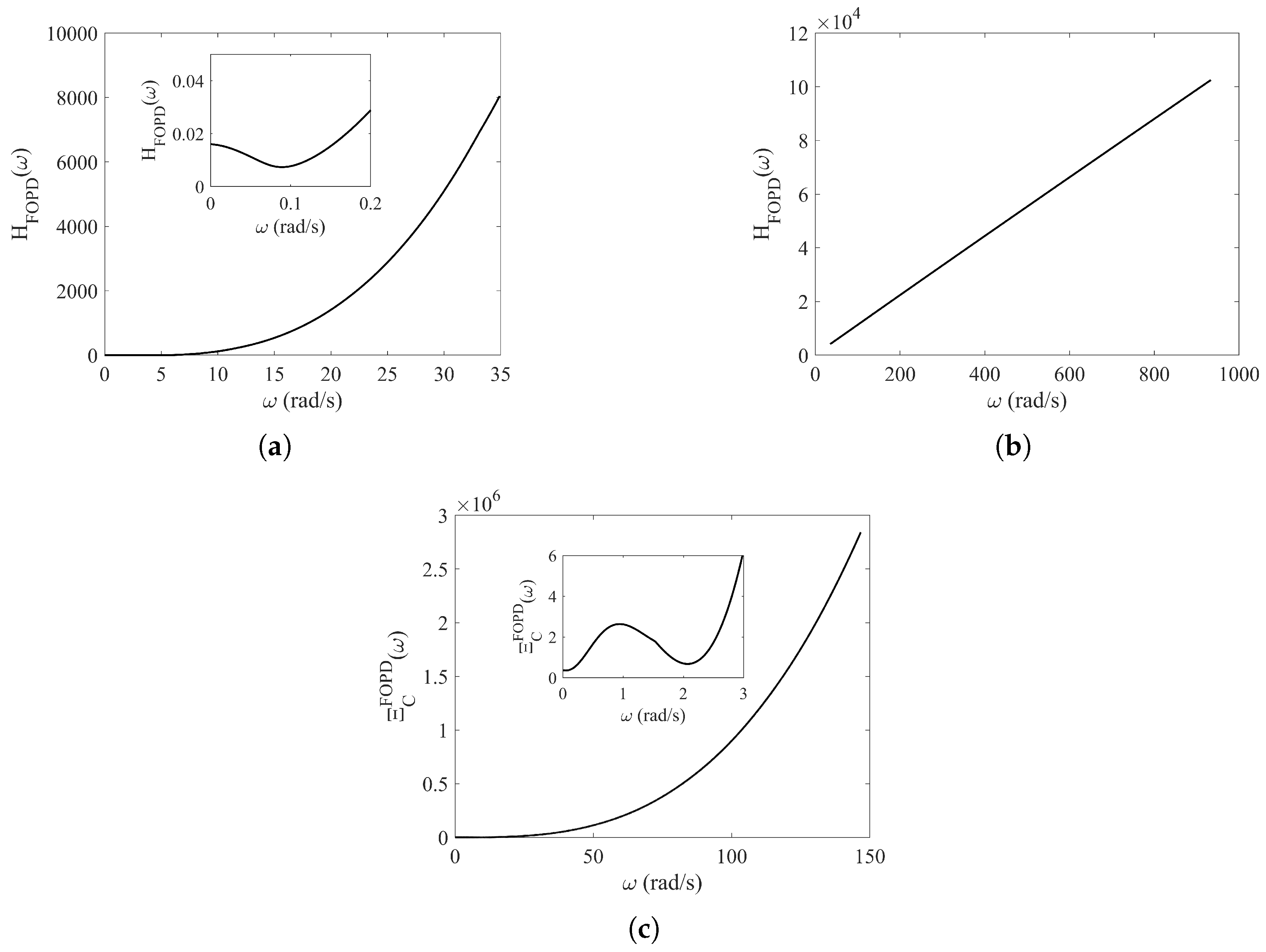
The frequency-domain verification of the controller obtained from Step 4 is shown in Figure 2. Figure 2a shows over rad/s, Figure 2b shows over rad/s, and Figure 2c shows over rad/s, with . The inequalities
remain satisfied over the corresponding sampled frequency intervals. For the low-frequency condition, is evaluated using the complete cluster intervals and , and the minimum is taken over the two clusters. For the high-frequency condition, uses the overall maximum eigenvalue . The minimum sampled values are on , on , and on . These positive margins provide sampled numerical evidence consistent with Theorem 2; because no interval-arithmetic or Lipschitz-bound validation is applied between adjacent samples, they are not presented as a rigorous continuous-frequency certificate.
Figure 2.
(a) Curve of for rad/s. (b) Curve of for rad/s. (c) Curve of for rad/s.
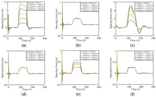
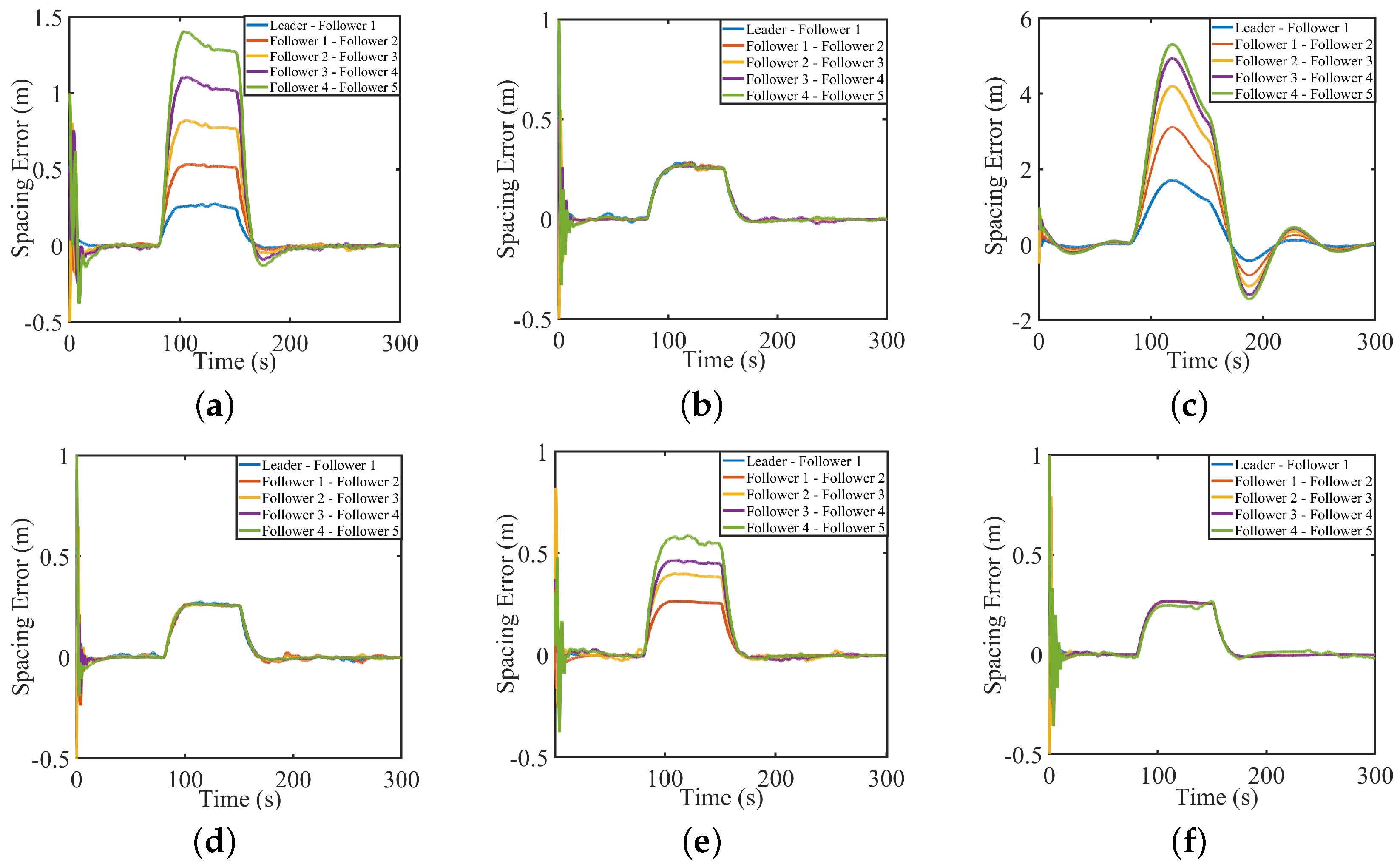
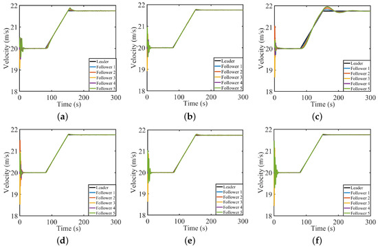
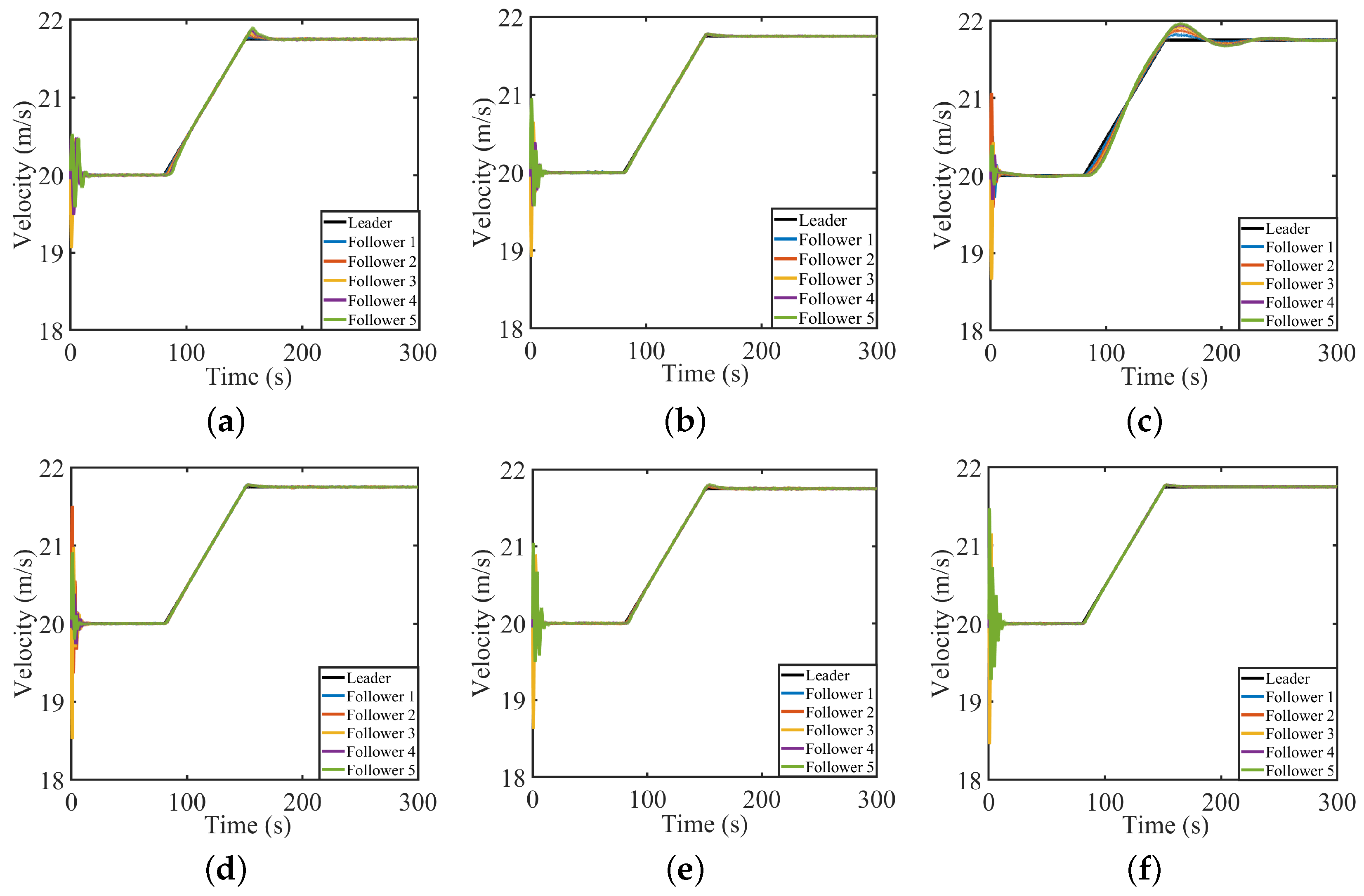
The time-domain responses are then used as an additional validation of the controller obtained from the frequency-domain tuning procedure. Figure 3 and Figure 4 present the spacing errors and velocities for the sampled uncertainty realisations. In all six topologies, the responses remain bounded and stable for the 100 sampled actuator lag and communication-delay realisations drawn from the stated intervals. This behaviour is consistent with the sampled robust stability inequalities enforced in Step 4 and provides complementary time-domain evidence for the tested realisations.
Figure 3.
Spacing errors for FOPD for (a) PF, (b) PFL, (c) BD, (d) BDL, (e) TPF, and (f) TPFL topologies.
Figure 4.
Velocities for FOPD for (a) PF, (b) PFL, (c) BD, (d) BDL, (e) TPF, and (f) TPFL topologies.
8.2. Comparative Performance of FOPD and PD Controllers Under Nominal and Uncertain Conditions
This subsection evaluates the closed-loop tracking performance of the proposed FOPD controller and compares it with the integer-order PD controller. The study is carried out on a heterogeneous platoon with ten follower vehicles . The comparison is performed under two conditions: nominal operation and operation with increased uncertainty. The vehicle models are treated as nonlinear, as reported in [40,54]. In the nominal case, identical vehicle parameters are used. In the uncertain case, heterogeneity is introduced through the parameter ranges, where , , , , and denote the vehicle mass, aerodynamic drag coefficient, rolling resistance coefficient, wheel radius, and transmission efficiency of the vehicle, respectively:
For the homogeneous nominal case, the midpoint values kg, , , m, and are assigned to every follower. For the heterogeneous case, the generator is reinitialised with rng(2026,’twister’) and R_v=rand(10,5) is generated. The columns of , in order, scale the intervals for , , , , and through . The resulting ten-vehicle parameter set is held fixed and reused for both controllers and all topologies, so controller comparisons use exactly the same plant realisation.
Performance is quantified through key performance indicators (KPIs) based on the maximum state error over each operating phase , where denotes the phase index. This is defined as
and the corresponding percentage improvement of the fractional-order controller over its integer-order counterpart,
where a positive value indicates better performance of the FOPD controller.
Assumption 4.
For the numerical simulations, the manoeuvre is piecewise constant.
The leader acceleration is defined as
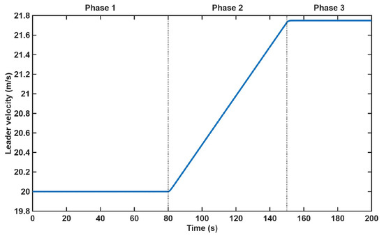
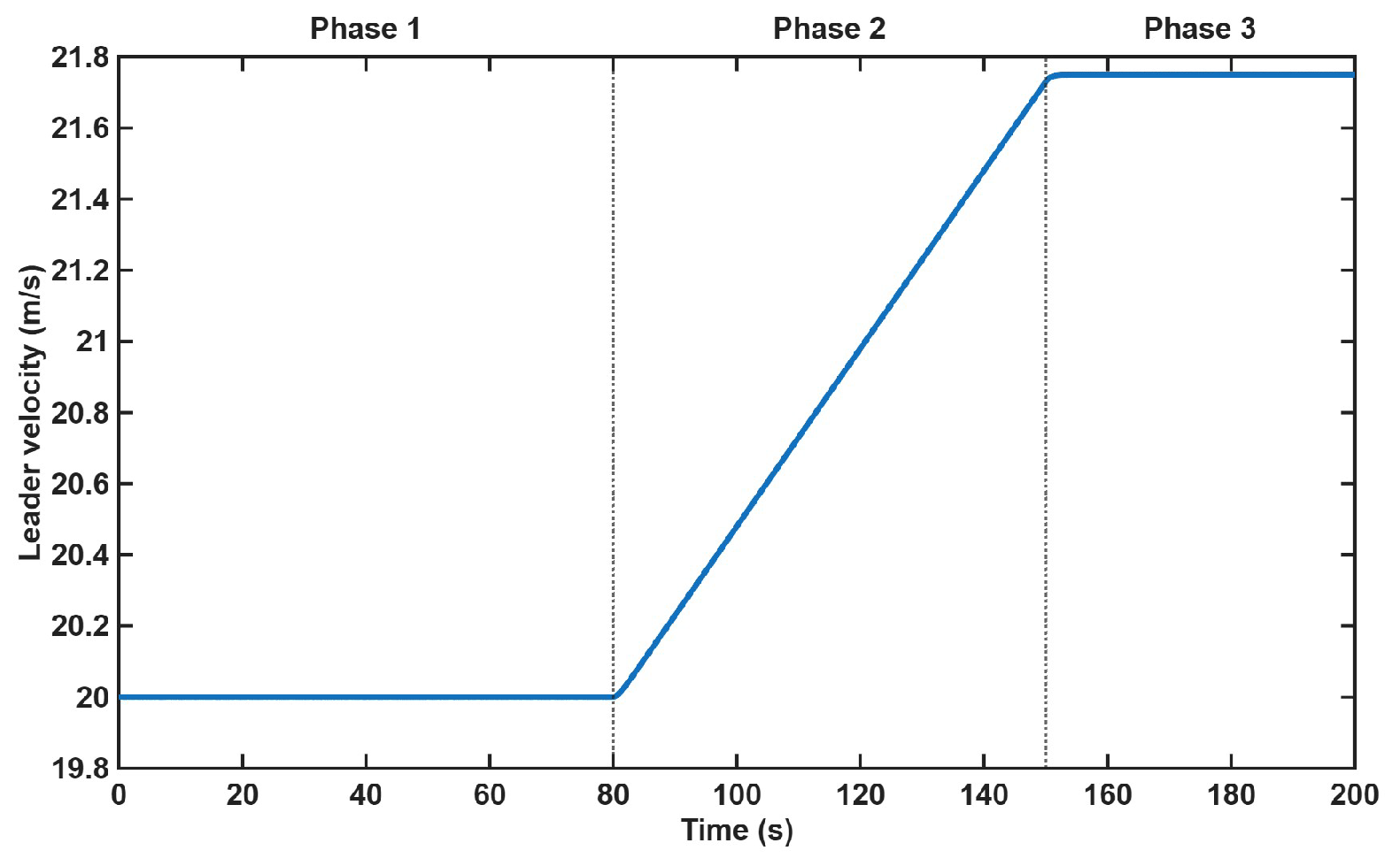
The corresponding leader velocity profile is shown in Figure 5, with three operating phases:
Figure 5.
Leader velocity profile showing the three phases: constant speed (Phase 1), constant acceleration m/s2 (Phase 2), and constant speed (Phase 3).
- (i)
- Phase 1 : uniform motion with .
- (ii)
- Phase 2 : constant acceleration with .
- (iii)
- Phase 3 : uniform motion resumes with .
The controller parameters used in this comparative study are listed in Table 1. The comparison reported here is a derivative-order comparison with fixed numerical parameter values rather than a comparison of independently tuned controllers. The integer-order PD case is obtained by setting , while retaining the numerical values and used in the FOPD case. Because the control law in (16) acts on spacing error and represents commanded acceleration, dimensional consistency requires to have units of and to have order-dependent units of . Accordingly, the tabulated value has units of for the FOPD controller with , and for the PD controller with . Thus, the two entries have the same numerical magnitude but do not represent dimensionally identical gains. The comparison evaluates the responses obtained by changing the derivative order while retaining the reported numerical parameter values and identical operating conditions. It should not be interpreted as a comparison with an independently optimised PD controller. Therefore, the reported results establish only the observed performance difference within this derivative-order comparison with fixed numerical parameter values and do not demonstrate superiority over an independently retuned PD controller or controllers based on different robust or predictive structures.
Table 1.
Controller gains and parameters for the derivative-order comparison.
8.2.1. Nominal Conditions
This case considers nominal conditions with actuator lag s and communication delay s for all followers. This nominal value represents an idealised low-latency operating point used only for the performance comparison; it is not part of the delay interval used in the sampled robust stability evaluation s. The platoon is homogeneous, with identical vehicle parameters. The purpose is to compare the performance of the distributed FOPD controller with its integer-order counterpart under ideal conditions. All nominal conditions are kept identical for both controllers to ensure a fair comparison.
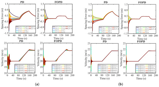
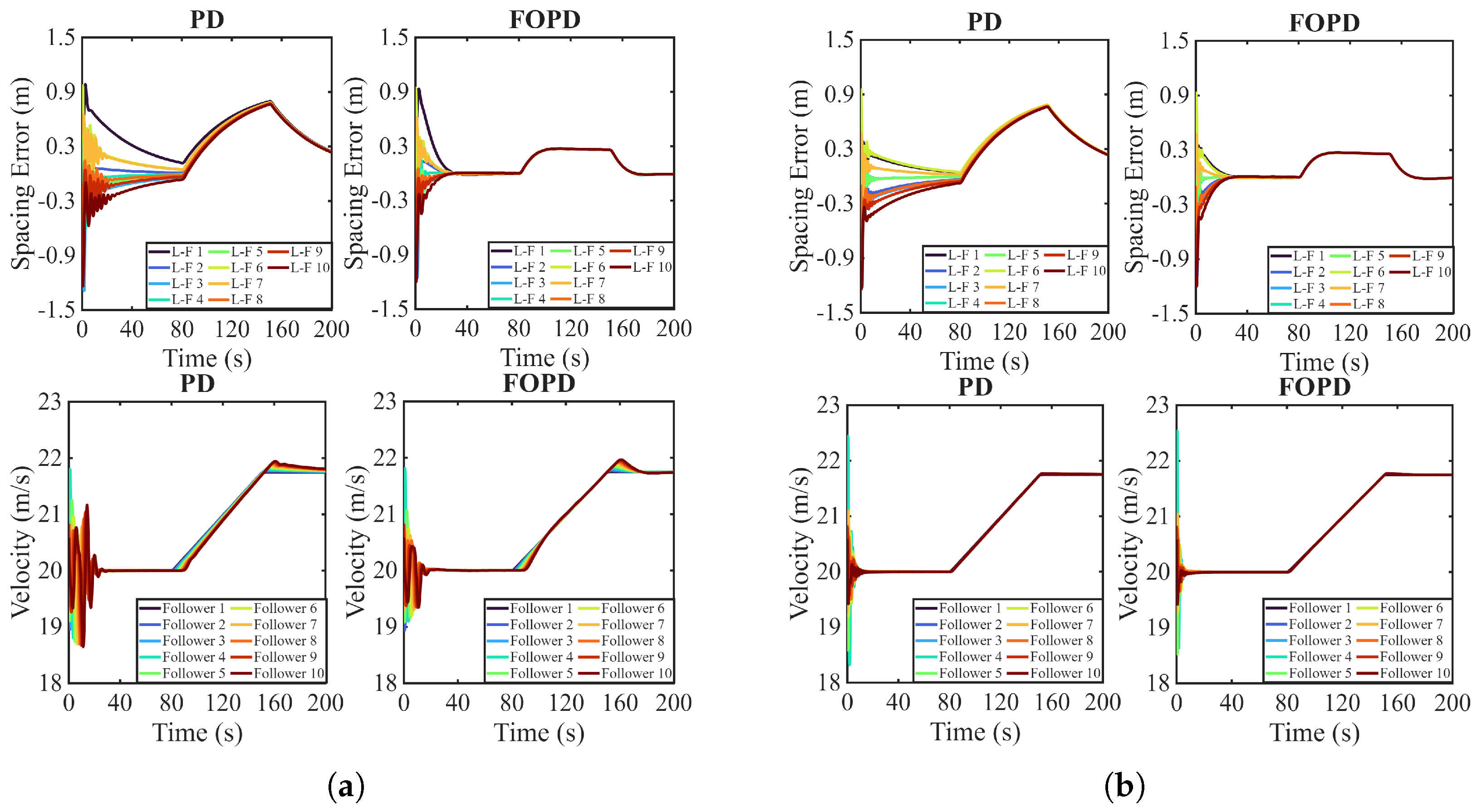
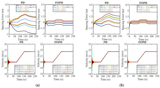
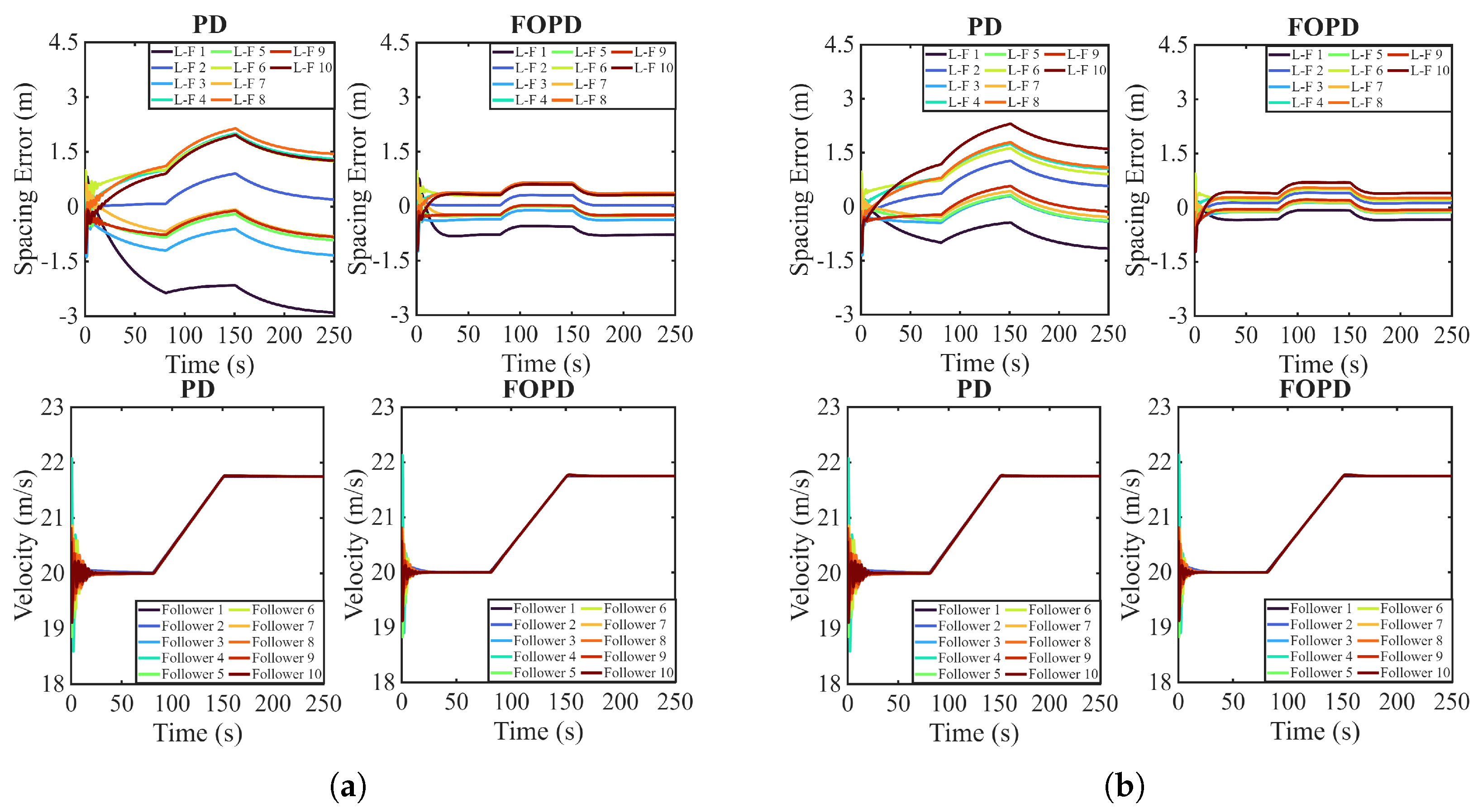
Quantitative performance is assessed through the defined KPIs for all six topologies, as summarised in Table 2. To illustrate the transient behaviour, Figure 6 shows the spacing errors and velocity responses for the PFL and BDL topologies. The upper plots show the spacing errors , while the lower plots show the follower velocities. The leader velocity profile follows the three phases defined by (60).
Table 2.
Percentage improvement in state errors (KPIs) under nominal conditions.
Figure 6.
Comparative responses under nominal conditions: FOPD vs. PD for (a) PFL topology and (b) BDL topology.
The PD controller exhibits noticeable oscillations, together with visible variation among the followers. By contrast, the FOPD controller produces better damped responses, with lower peak errors and shorter settling times. This is consistent with the results in Table 2, where the positive values of and across all topologies indicate a substantial reduction in spacing errors. The improvement in Phase 1 is smaller because the leader moves at a constant speed and the spacing error is naturally limited. Negative acceleration KPIs, , arise from the greater sensitivity of the fractional derivative term to the switching instants at s and s. Hence, the improved damping in spacing is accompanied by slightly larger short-duration acceleration mismatches at the phase transitions.
8.2.2. Robustness to Uncertainties
In this case, larger mismatches and communication latency are introduced to compare the robustness of the distributed FOPD controller with that of the integer-order version. The platoon is non-homogeneous, the vehicle parameters are varied within the heterogeneous ranges specified above, and the communication delay is extended to s. The actuator lag is retained at s in this matched-plant performance comparison; interval actuator lag uncertainty is evaluated separately in Section 8.1. To ensure fair comparisons, the communication delays and model mismatches are kept the same for both controllers.
Under these uncertainties, as illustrated in Figure 7, the PD controller shows larger oscillations, which cause higher spacing errors and increase the dispersion among followers. However, the FOPD controller has a better damped response and maintains the platoon formation more effectively. This behaviour is reflected in Table 3, where the values of both and are positive for all topologies. The Phase 1 improvement is also larger than in the nominal case; for the PFL topology, it increases from to . This indicates that the PD controller degrades more severely as the delay and model mismatch increase, whereas the FOPD controller preserves better damping. Velocity responses also show reduced oscillation, as indicated by the positive values of . Negative acceleration KPIs still occur because of temporary peaks and model mismatch.
Figure 7.
Comparative responses under uncertain conditions: FOPD vs PD for (a) PFL topology and (b) BDL topology.
Table 3.
Percentage improvement in state errors (KPIs) under uncertain conditions.
9. Conclusions
An effective stability analysis and design framework of distributed fractional-order controllers, i.e., the FOPD controller, for vehicle platoons with actuator and communication delay uncertainties has been introduced. Verification of robust stability under interval uncertainties without exhaustive gridding of the uncertain parameter combinations is facilitated by the auxiliary function formulation, and the controller parameters are determined by an optimisation-based process. For a five-follower platoon with six communication topologies, the developed theorem gives continuous-frequency sufficient conditions for actuator lags in s and communication delays in s. The reported controller satisfies these inequalities on the explicitly stated frequency grids with positive sampled margins; this numerical result is evidence consistent with the theorem rather than a validated continuous-frequency certificate. Eigenvalue clustering reduces computational effort while introducing a controllable level of conservatism and demonstrates that stability depends only on the distinct eigenvalues of the information matrix. The performance of the FOPD controller was also compared with that of a PD baseline using the same numerical controller-parameter values in a heterogeneous ten-follower platoon. In nominal conditions, the spacing-error KPIs are positive in all topologies that are considered, with the largest improvement reaching . Velocity tracking is also enhanced, though small transient growths on acceleration mismatch can be seen near the switching instant. Under uncertain conditions, with plant-model mismatch introduced through the heterogeneous parameter ranges and s, the peak improvement in the spacing-error is , and the velocity responses are better damped and less oscillatory than those of the PD controller.
Within the tested derivative-order comparison using the same numerical parameter values, the FOPD controller provides higher damping and better formation coherence than its integer-order PD counterpart under the stated nominal and uncertain conditions. This comparison is not intended to establish superiority over controllers with different robust or predictive structures.
Future Work
The present paper addresses internal robust stability but does not establish string stability. Future research will therefore analyse disturbance amplification and attenuation along the vehicle string under delays and uncertainties. Further work will also consider packet loss, link-dependent time-varying latency, switching information flow topologies, and the analytical determination of the maximum tolerable communication delay.
Author Contributions
Conceptualization, M.G. and O.H.; methodology, M.G. and O.H.; software, M.G. and O.H.; formal analysis, M.G. and O.H.; investigation, M.G. and O.H.; validation, M.G. and O.H.; writing—original draft preparation, M.G. and O.H.; funding acquisition, M.G. and O.H.; writing—review and editing, U.M.; supervision, U.M., P.G., A.S., K.N., A.T. and E.P. All authors have read and agreed to the published version of the manuscript.
Funding
This research was funded by the Estonian Research Council, grant number PRG658, and the Engineering and Physical Sciences Research Council (EPSRC), UK, Project Reference Number 2757376.
Informed Consent Statement
Not applicable.
Data Availability Statement
The original contributions presented in this study are included in the article. Further inquiries can be directed to the corresponding authors.
Conflicts of Interest
The authors declare no conflicts of interest. The funders had no role in the design of the study, in the collection, analysis, or interpretation of data, in the writing of the manuscript, or in the decision to publish the results.
Appendix A. Stability Analysis Under Repeated Real Eigenvalues
This appendix addresses the case in which the information matrix possesses repeated real eigenvalues. The following lemma establishes that controller tuning depends solely on the distinct eigenvalues, regardless of their algebraic multiplicities.
Lemma A1.
Consider an information matrix with m distinct real eigenvalues , where each has algebraic multiplicity for . Upon applying the transformation to the closed-loop platoon error dynamics governed by the distributed FOPD, the transformed error vector in the Laplace domain satisfies
where aggregates terms arising from initial conditions, leader acceleration, and external disturbances. The matrix is block-diagonal with m blocks,
Each block exhibits a Jordan-like (upper-bidiagonal) structure given by
in which denotes a scalar characteristic term determined by the control strategy, is a scalar characteristic function dependent on both the controller gains and the eigenvalue , and represents the nilpotent matrix
When all zeros of , , lie in the open left half-plane, all poles generated by remain in the open left half-plane for every . Consequently, controller gain tuning for guaranteed stability is determined exclusively by the distinct eigenvalues of and remains independent of eigenvalue multiplicities.
Proof.
The vectors and are partitioned conformably as
with for . Exploiting the block-diagonal structure of in (A2), each block error satisfies
Utilising the Jordan-like structure of in (A3), the inverse matrix adopts an explicit upper-triangular representation
from which the q-th component of the i-th block error becomes
When all zeros of , , lie in the open left half-plane, all poles generated by remain in the open left half-plane for every . Consequently, all components exhibit stable behaviour. This demonstrates that stability criteria are governed exclusively by the m polynomials corresponding to the distinct eigenvalues of , irrespective of the algebraic multiplicities . □
References
- Martínez-Díaz, M.; Al-Haddad, C.; Soriguera, F.; Antoniou, C. Impacts of platooning of connected automated vehicles on highways. IEEE Trans. Intell. Transp. Syst. 2024, 25, 6366–6396. [Google Scholar] [CrossRef] [Scilit]
- Ge, X.H.; Han, Q.L.; Zhang, X.M.; Ding, D. Communication resource-efficient vehicle platooning control with various spacing policies. IEEE/CAA J. Autom. Sinica 2024, 11, 362–376. [Google Scholar] [CrossRef] [Scilit]
- Olfati-Saber, R.; Fax, J.A.; Murray, R.M. Consensus and cooperation in networked multi-agent systems. Proc. IEEE 2007, 95, 215–233. [Google Scholar] [CrossRef] [Scilit]
- Li, W.; Yan, S.; Shi, L.; Yue, J.; Shi, M.; Lin, B.; Qin, K. Multiagent consensus tracking control over asynchronous cooperation–competition networks. IEEE Trans. Cybern. 2025, 55, 4347–4360. [Google Scholar] [CrossRef] [Scilit] [PubMed]
- Shi, L.; Yan, S.; Li, W. Consensus and products of substochastic matrices: Convergence rate with communication delays. IEEE Trans. Syst. Man Cybern. Syst. 2025, 55, 4752–4761. [Google Scholar] [CrossRef] [Scilit]
- Li, S.E.; Zheng, Y.; Li, K.; Wu, Y.; Hedrick, J.K.; Gao, F.; Zhang, H. Dynamical modeling and distributed control of connected and automated vehicles: Challenges and opportunities. IEEE Intell. Transp. Syst. Mag. 2017, 9, 46–58. [Google Scholar] [CrossRef] [Scilit]
- Li, S.E.; Zheng, Y.; Li, K.; Wang, J. An overview of vehicular platoon control under the four-component framework. In Proceedings of the 2015 IEEE Intelligent Vehicles Symposium (IV), Seoul, Republic of Korea, 28 June–1 July 2015; pp. 286–291. [Google Scholar]
- Hanif, O.; Gruber, P.; Sorniotti, A.; Montanaro, U. A review of control solutions for vehicle platooning via network synchronisation methods. Automation 2026, 7, 35. [Google Scholar] [CrossRef] [Scilit]
- Pi, D.; Xue, P.; Wang, W.; Xie, B.; Wang, H.; Wang, X.; Yin, G. Automotive platoon energy-saving: A review. Renew. Sustain. Energy Rev. 2023, 179, 113268. [Google Scholar] [CrossRef] [Scilit]
- Yang, Z.; Wang, L.; Yu, Z.; Wang, H.; Sun, W. Energy efficient strategy for heterogeneous truck platooning based on a non-uniform platooning model. Sci. Rep. 2024, 14, 28777. [Google Scholar] [CrossRef] [Scilit] [PubMed]
- Rebelo, M.; Rafael, S.; Bandeira, J.M. Vehicle platooning: A detailed literature review on environmental impacts and future research directions. Future Transp. 2024, 4, 591–607. [Google Scholar] [CrossRef] [Scilit]
- Hao, H.; Barooah, P. Stability and robustness of large platoons of vehicles with double-integrator models and nearest neighbor interaction. Int. J. Robust Nonlinear Control 2013, 23, 2097–2122. [Google Scholar] [CrossRef] [Scilit]
- Ghasemi, A.; Kazemi, R.; Azadi, S. Exact stability of a platoon of vehicles by considering time delay and lag. J. Mech. Sci. Technol. 2015, 29, 799–805. [Google Scholar] [CrossRef] [Scilit]
- Chen, N.; Wang, M.; Alkim, T.; van Arem, B. A robust longitudinal control strategy of platoons under model uncertainties and time delays. J. Adv. Transp. 2018, 2018, 9852721. [Google Scholar] [CrossRef] [Scilit]
- Liu, B.; Gao, F.; He, Y.; Wang, C. Robust control of heterogeneous vehicular platoon with non-ideal communication. Electronics 2019, 8, 207. [Google Scholar] [CrossRef] [Scilit]
- Di Vaio, M.; Petrillo, A.; Santini, S. On the robustness of a distributed adaptive synchronization protocol for connected autonomous vehicles with multiple disturbances and communication delays. In Proceedings of the IEEE Conference on Decision and Control (CDC), Miami Beach, FL, USA, 17–19 December 2018; pp. 3622–3627. [Google Scholar]
- Wang, J.; Zheng, H.; Guo, J.; Fan, J.; Li, K. Distributed adaptive robust H∞ control of intelligent-connected electric vehicles platooning subject to communication delay. IET Intell. Transp. Syst. 2021, 15, 699–711. [Google Scholar] [CrossRef] [Scilit]
- Li, J.; Wang, L.; Xu, M.; Fang, Y. Adaptive event-triggered robust model predictive control for multiagent systems with time-varying delay under arbitrary network topology. IEEE Syst. J. 2023, 17, 5381–5392. [Google Scholar] [CrossRef] [Scilit]
- Fiengo, G.; Lui, D.G.; Petrillo, A.; Santini, S.; Tufo, M. Distributed robust PID control for leader tracking in uncertain connected ground vehicles with V2V communication delay. IEEE/ASME Trans. Mechatron. 2019, 24, 1153–1165. [Google Scholar] [CrossRef] [Scilit]
- Ma, F.; Wang, J.; Yang, Y.; Wu, L.; Zhu, S.; Gelbal, S.Y.; Aksun-Guvenc, B.; Guvenc, L. Stability design for the homogeneous platoon with communication time delay. Automot. Innov. 2020, 3, 101–110. [Google Scholar] [CrossRef] [Scilit]
- Gaagai, R.; Horn, J. Distributed safety-critical control for linear homogeneous vehicle platoons subject to actuator and communication delays. In Proceedings of the IEEE Conference on Decision and Control (CDC), Milan, Italy, 16–19 December 2024; pp. 8376–8383. [Google Scholar]
- Chu, J.; Wu, Q.; Fan, P.; Chen, W.; Wang, K.; Cheng, N.; Letaief, K.B. V2X-assisted distributed computing and control framework for connected and automated CAVs under ramp merging scenario. IEEE Trans. Mob. Comput. 2026, 25, 7436–7453. [Google Scholar] [CrossRef] [Scilit]
- Oustaloup, A.; Cois, O.; Lanusse, P.; Melchior, P.; Moreau, X.; Sabatier, J. The CRONE approach: Theoretical developments and major applications. In Proceedings of the 2nd IFAC Workshop on Fractional Differentiation and Its Applications, Porto, Portugal, 19–21 July 2006; pp. 324–354. [Google Scholar]
- Viola, J.; Angel, L.; Sebastian, J.M. Design and robust performance evaluation of a fractional order PID controller applied to a DC motor. IEEE/CAA J. Autom. Sinica 2017, 4, 304–314. [Google Scholar] [CrossRef] [Scilit]
- Liu, L.; Zhang, S.; Xue, D.; Chen, Y.Q. General robustness analysis and robust fractional-order PD controller design for fractional-order plants. IET Control Theory Appl. 2018, 12, 1730–1736. [Google Scholar] [CrossRef] [Scilit]
- Lu, J.G.; Chen, Y.Q. Robust stability and stabilization of fractional-order interval systems with the fractional order α: The 0 < α < 1 case. IEEE Trans. Autom. Control 2010, 55, 152–158. [Google Scholar] [CrossRef] [Scilit]
- Badau, N.E.; Popescu, T.M.; Mihai, M.D.; Birs, I.R.; Muresan, C.I. A robust fractional-order controller for biomedical applications. Fractal Fract. 2025, 9, 597. [Google Scholar] [CrossRef] [Scilit]
- Martins-Gomes, M.C.; de Carvalho Ayres Junior, F.A.; da Costa Junior, C.T.; de Bessa, I.V.; Nei, N.J.; de Medeiros, R.L.P.; Silva, L.E.S.; de Lucena Júnior, V.F. Fractional-order robust control design under parametric uncertain approach. ISA Trans. 2024, 153, 420–432. [Google Scholar] [CrossRef] [Scilit] [PubMed]
- Podlubny, I. Fractional Differential Equations: An Introduction to Fractional Derivatives, Fractional Differential Equations, to Methods of Their Solution and Some of Their Applications; Academic Press: San Diego, CA, USA, 1999. [Google Scholar]
- Monje, C.A.; Chen, Y.Q.; Vinagre, B.M.; Xue, D.; Feliu-Batlle, V. Fractional-Order Systems and Controls: Fundamentals and Applications; Springer: London, UK, 2010. [Google Scholar]
- Hanif, O.; Kedia, V. Evolution of proportional integral derivative controller. In Proceedings of the International Conference on Recent Innovations in Electrical, Electronics & Communication Engineering (ICRIEECE), Bhubaneswar, India, 27–28 July 2018; pp. 2655–2659. [Google Scholar]
- Hanif, O.; Chatterjee, M.; Deshpande, N.G.; Bhatnagar, A.; Babu, G.U.B. Design and analysis of fractional-order PID controller and its variants for nonlinear process using Kalman filter. In Proceedings of the 2020 International Conference on Computing, Electronics & Communications Engineering (iCCECE), Virtual, 17–18 August 2020. [Google Scholar]
- Flores, C.; Milanés, V.; Nashashibi, F. Using fractional calculus for cooperative car-following control. In Proceedings of the IEEE International Conference on Intelligent Transportation Systems (ITSC), Rio de Janeiro, Brazil, 1–4 November 2016; pp. 907–912. [Google Scholar]
- Flores, C.; Muñoz, J.; Monje, C.A.; Milanés, V.; Lu, X.Y. Iso-damping fractional-order control for robust automated car-following. J. Adv. Res. 2020, 25, 181–189. [Google Scholar] [CrossRef] [Scilit] [PubMed]
- Flores, C.; Milanés, V. Fractional-order-based ACC/CACC algorithm for improving string stability. Transp. Res. Part C Emerg. Technol. 2018, 95, 381–393. [Google Scholar] [CrossRef] [Scilit]
- Dadras, S.; Dadras, S.; Winstead, C. Resilient control design for vehicular platooning in an adversarial environment. In Proceedings of the American Control Conference (ACC), Philadelphia, PA, USA, 10–12 July 2019; pp. 533–538. [Google Scholar]
- Wang, J.; Hu, W.; Cui, Y.; Yu, Y. Adaptive fractional-order PID controller design and parameter tuning for vehicle longitudinal control. In Proceedings of the International Conference on New Trends in Computational Intelligence (NTCI), Guiyang, China, 18–20 October 2024; pp. 417–421. [Google Scholar]
- Hanif, O.; Gruber, P.; Sorniotti, A.; Montanaro, U. Network-based fractional-order control algorithms for vehicle platooning. IEEE Access 2025, 13, 139992–140011. [Google Scholar] [CrossRef] [Scilit]
- Halder, K.; Montanaro, U.; Dixit, S.; Dianati, M.; Mouzakitis, A.; Fallah, S. Distributed H∞ controller design and robustness analysis for vehicle platooning under random packet drop. IEEE Trans. Intell. Transp. Syst. 2022, 23, 4373–4386. [Google Scholar] [CrossRef] [Scilit]
- Wen, S.; Guo, G. Sampled-data control for connected vehicles with Markovian switching topologies and communication delay. IEEE Trans. Intell. Transp. Syst. 2020, 21, 2930–2942. [Google Scholar] [CrossRef] [Scilit]
- Zhu, Y.; Wu, J.; Su, H. V2V-based cooperative control of uncertain, disturbed and constrained nonlinear CAVs platoon. IEEE Trans. Intell. Transp. Syst. 2022, 23, 1796–1806. [Google Scholar] [CrossRef] [Scilit]
- Rajendran, S.; Spurgeon, S.K.; Tsampardoukas, G.; Hampson, R. Estimation of road frictional force and wheel slip for effective antilock braking system (ABS) control. Int. J. Robust Nonlinear Control 2019, 29, 736–765. [Google Scholar] [CrossRef] [Scilit]
- Grip, H.F.; Imsland, L.; Johansen, T.A.; Fossen, T.I.; Kalkkuhl, J.C.; Suissa, A. Nonlinear vehicle velocity observer with road–tire friction adaptation. In Proceedings of the IEEE Conference on Decision and Control, San Diego, CA, USA, 13–15 December 2006; pp. 3603–3608. [Google Scholar]
- Li, S.; Sun, Z.; Liu, Y.; Ji, A.; Zhang, S.; Chen, L. Coupled lateral and longitudinal trajectory tracking control with a modified vehicle kinematics model for autonomous vehicles. Intell. Transp. Infrastruct. 2023, 2, liad009. [Google Scholar] [CrossRef] [Scilit]
- Marden, M. Geometry of Polynomials; Mathematical Surveys, No. 3; American Mathematical Society: Providence, RI, USA, 1949. [Google Scholar]
- Moornani, K.A.; Haeri, M. On robust stability of LTI fractional-order delay systems of retarded and neutral type. Automatica 2010, 46, 362–368. [Google Scholar] [CrossRef] [Scilit]
- Tan, N.; Ozguven, O.F.; Ozyetkin, M.M. Robust stability analysis of fractional order interval polynomials. ISA Trans. 2009, 48, 166–172. [Google Scholar] [CrossRef] [Scilit] [PubMed]
- Bhattacharyya, S.P.; Keel, L.H. Robust control: The parametric approach. In Advances in Control Education 1994; Elsevier: Amsterdam, The Netherlands, 1995; pp. 49–52. [Google Scholar]
- Konduri, S. Robust String Stability of Vehicle Platoons with Communication and Actuation Uncertainties. Ph.D. Thesis, Texas A&M University, College Station, TX, USA, 2017. [Google Scholar]
- Gao, F.; Li, S.E.; Zheng, Y.; Ren, W. Robust control of heterogeneous vehicular platoon with communication delay and uncertain nonlinear dynamics. IET Intell. Transp. Syst. 2016, 10, 503–513. [Google Scholar] [CrossRef] [Scilit]
- Gao, H.; Zhuang, L.; Lim, E.P.; Bevly, A.M. An empirical study of DSRC V2V performance in truck platooning scenarios. Digit. Commun. Netw. 2016, 2, 233–244. [Google Scholar] [CrossRef] [Scilit]
- Hu, M.; Zhao, X.; Xiao, G.; Wang, W. Modeling and analysis on minimum safe distance for platooning vehicles. J. Adv. Transp. 2021, 2021, 5543114. [Google Scholar] [CrossRef] [Scilit]
- Wang, L.Y.; Yin, G.; Zhang, H. Communication information structures and contents for enhanced safety of highway vehicle platoons. IEEE Trans. Veh. Technol. 2014, 63, 4206–4220. [Google Scholar] [CrossRef] [Scilit]
- Feng, J.; Gao, Z.; Guo, B. State-feedback and nonsmooth controller design for truck platoon subject to uncertainties and disturbances. World Electr. Veh. J. 2024, 15, 251. [Google Scholar] [CrossRef] [Scilit]

Disclaimer/Publisher’s Note: The statements, opinions and data contained in all publications are solely those of the individual author(s) and contributor(s) and not of MDPI and/or the editor(s). MDPI and/or the editor(s) disclaim responsibility for any injury to people or property resulting from any ideas, methods, instructions or products referred to in the content. |
© 2026 by the authors. Licensee MDPI, Basel, Switzerland. This article is an open access article distributed under the terms and conditions of the Creative Commons Attribution (CC BY) license.