


Abstract
Optical inspection of highly reflective cylindrical components—such as stainless-steel vessels featuring both planar and curvilinear surfaces—presents significant challenges due to complex geometric distortions in single-pass imaging. This study proposes a line-scan imaging framework that integrates synchronized kinematic control with geometry-aware distortion correction. The system addresses shape deformations through three coordinated modules: (1) parametric synchronization between rotational motion and image acquisition ensures full-surface coverage; (2) scanline-specific 1D projective transformations correct perspective distortions on toroidal sidewalls; and (3) adaptive polar coordinate remapping restores radial symmetry on circular bases. Experimental results demonstrate subpixel-level geometric correction accuracy, validating the proposed framework’s effectiveness in eliminating geometric aberrations with low computational complexity and without reliance on data-driven training, while maintaining compatibility with defect detection and quantitative surface analysis of specular cylindrical specimens.
1. Introduction
Accurate imaging of highly reflective cylindrical surfaces is a critical requirement in industrial quality inspection, particularly for components such as aerospace and automotive engine casings, stainless steel vessels, and polished pipeline segments [1,2]. Due to their specular surfaces and compound curvatures, such objects present two primary challenges in optical imaging: intense specular reflections that degrade defect visibility and severe geometric distortions induced by oblique viewing angles and curved surface projections. Therefore, acquiring undistorted images of the polished cylindrical sidewall and circular bottom surfaces of these components is crucial for ensuring effective defect detection.
While area-array cameras are widely used, they often suffer from occlusions and limited field of view when applied to highly reflective cylindrical bodies of revolution, making them unsuitable for complete surface coverage in a single pass [3,4,5,6,7]. Line-scan imaging with dark-field illumination addresses these limitations by offering high-resolution, continuous surface mapping through the synchronization of image acquisition with object motion [8,9,10,11]. Nevertheless, line-scan systems applied to compound curved surfaces still encounter two fundamental limitations: (1) perspective distortion along the scanning axis due to non-perpendicular incidence and (2) circular-to-rectangular projection distortion on the base, which conventional 2D homography cannot adequately address.
In recent years, significant efforts have been made to address distortion correction in line-scan imaging of curved and reflective surfaces. Mainstream geometric correction technologies primarily focus on processing planar projection images. These methods rely on establishing correspondences between the object plane and the image plane to transform planar projections, thereby achieving geometric distortion correction [12,13,14,15]. Additionally, Li and Yu et al. [16,17] proposed methods using deep neural networks that offer end-to-end correction but require extensive labeled datasets and often lack interpretability for varying geometries. However, these approaches are designed for planar surfaces and cannot be directly applied to cylindrical geometries.
Common image correction techniques include affine transformation [18,19,20] and perspective transformation [21,22,23]. Pei et al. [24] employed 1D row and column fractional space shifts or shearing to perform affine transformations on two-dimensional images, aligning them to the desired positions. However, these planar mapping methods are not suitable for the imaging characteristics of line-scan cameras. In response, Moutsis and Yang et al. [25,26] used projective polar coordinate transformations to reduce the image from a 2D vector to a 1D vector, thereby decreasing the computational load of the mapping and matching process. Yang et al. [27] addressed distortion in curved prism imaging using linear features and cross-ratio invariance, while Zhang et al. [28] applied 1D projective transformations to map images captured at inclined angles. Nevertheless, few works have tackled distortion correction under the combined constraints of high reflectivity, compound curvature, and single-line-scan acquisition [29,30,31].
To address these challenges, we propose a unified geometric correction framework based on 1D projective and polar mapping. Our method exploits the intrinsic row-wise independence of line-scan imaging, applying a scanline-specific 1D projective transform to the sidewall region and an adaptive polar mapping to restore radial symmetry in the base region. This hybrid approach not only reduces computational complexity from to , but also preserves local geometry without global warping.
The main contributions of this work are as follows:
- (1)
- A line-scan imaging system incorporating synchronized rotation and dark-field illumination is developed for highly reflective cylindrical objects.
- (2)
- A 1D projective–polar geometric correction method is introduced, enabling unified rectification of both sidewall and base distortions.
- (3)
- Theoretical analysis and experimental validation are conducted on representative reflective cylindrical objects, demonstrating subpixel accuracy and robustness.
2. Materials and Methods
2.1. Single-Line-Scan Imaging System Hardware and Configuration
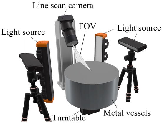
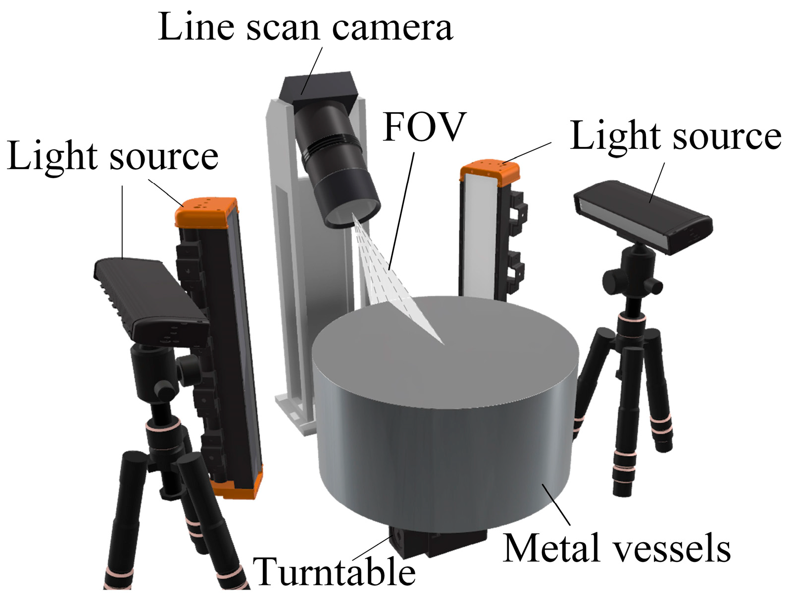
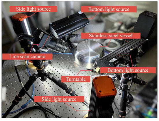
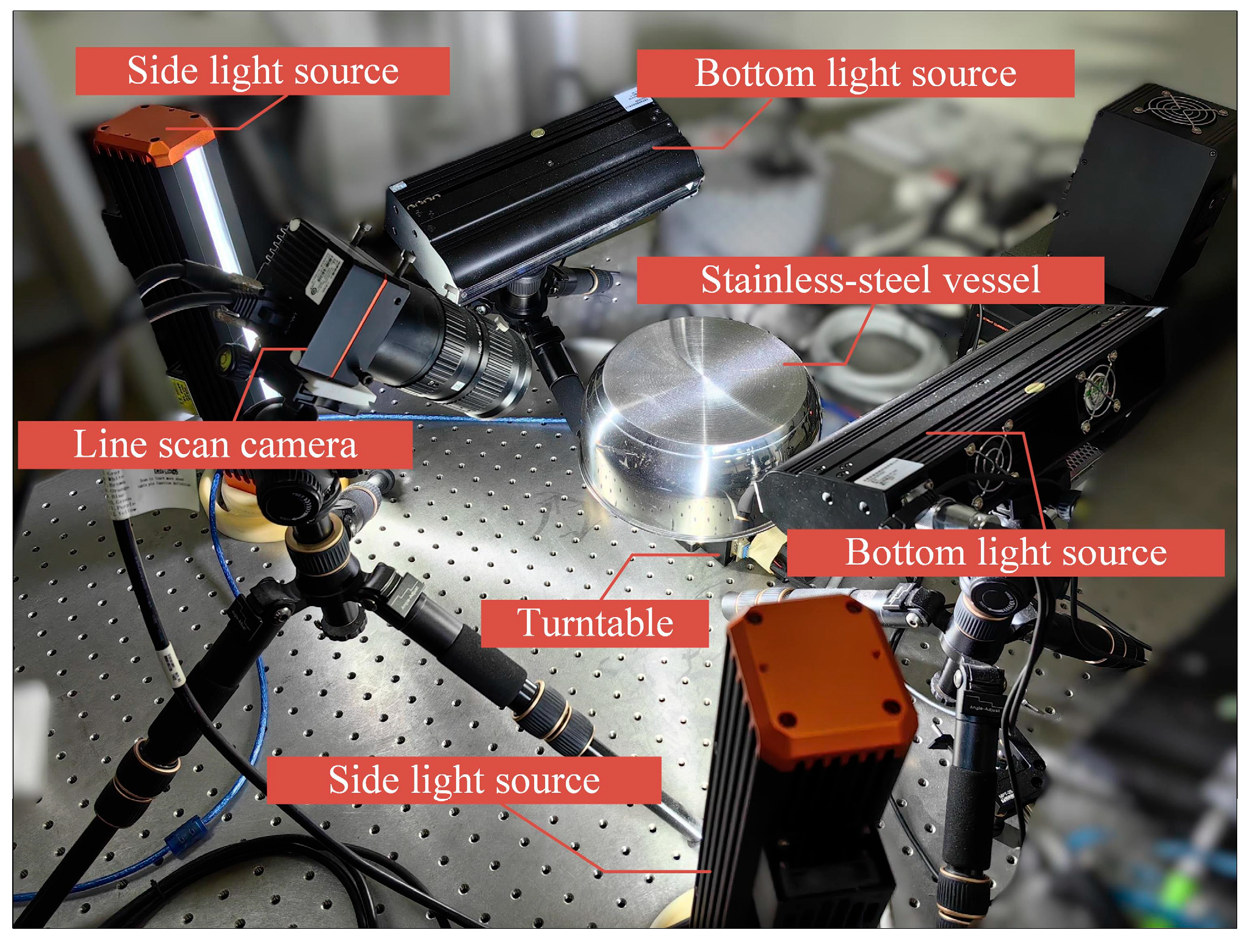
Cylindrical metallic vessels exhibit a composite geometric structure comprising a planar base and sidewalls with continuous curvature. This study employs an imaging strategy that combines a line-scan camera with a rotational platform, enabling single-pass continuous imaging acquisition for both the base and exterior sidewalls. Considering the specular reflection of metallic surfaces, excessive irradiance may induce sensor saturation, resulting in dynamic range compression and information loss [32,33]. Accordingly, we design a composite lighting scheme consisting of multiple low-angle linear light arrays. This configuration suppresses direct reflections and enhances the contrast of surface defects. The system architecture is illustrated in Figure 1.
Figure 1.
Single-line-scan image acquisition system model.
The line-scan camera requires a complete image of the vessel’s external surface to avoid image blur or distortion. Consequently, the rotational speed of the turntable must match the line frequency of the camera. When the turntable is driven by a DC motor under steady-state operation, the relationship can be expressed as:
where is the rotational speed, is the DC voltage, is the DC current, is the total circuit resistance, is the motor structural parameter, is the magnetic flux, and is the transmission ratio between the motor and the turntable.
Precise synchronization between the camera’s acquisition frequency and the turntable’s angular displacement is required. The relationship between rotational speed and line frequency satisfy:
where is the diameter of the container and is the pixel accuracy.
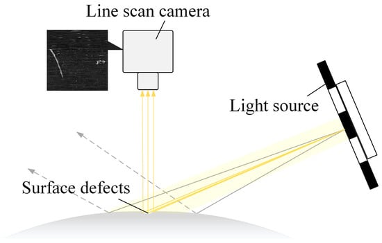
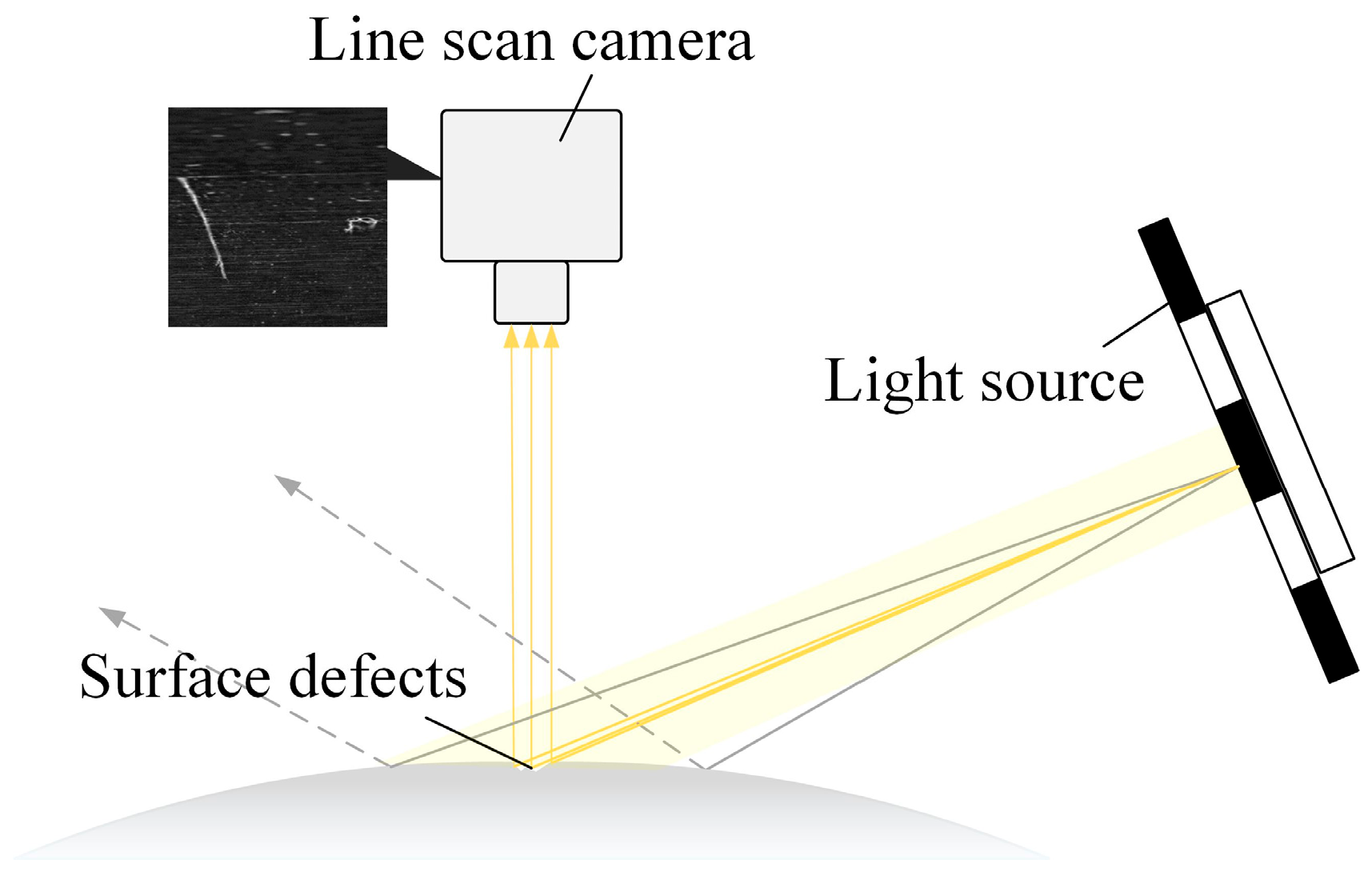
The dark-field illumination model is illustrated in Figure 2. This configuration employs four linear light sources positioned at low oblique angles outside the camera’s field of view. This setup ensures that the camera captures only diffusely scattered defect highlights while suppressing specular reflections. The linear sources are organized into two symmetric pairs. One pair is dedicated to the cylindrical sidewall and the other to the base plane.
Figure 2.
Dark-field illumination model structure.
2.2. Geometry-Aware 1D Projective–Polar Mapping Correction
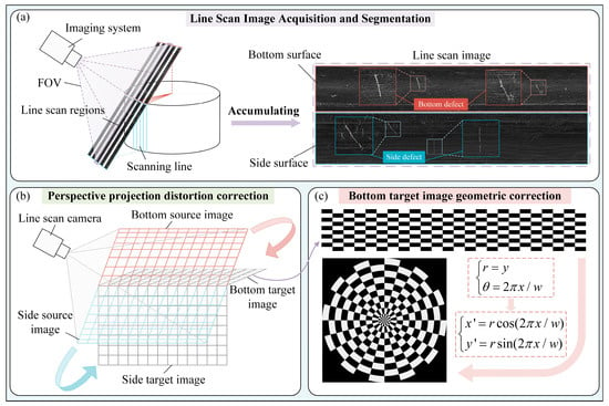
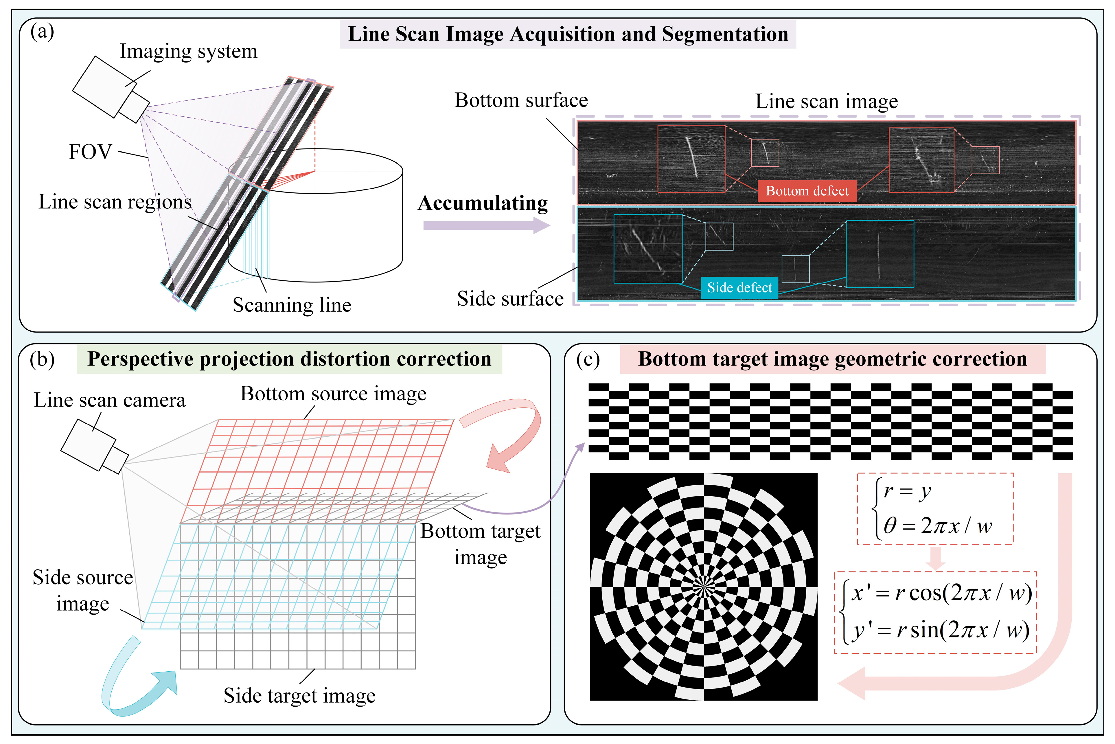
This section addresses the severe geometric distortion encountered in single-pass full-coverage imaging of vessels’ external surfaces by proposing a line-scan image distortion correction algorithm, as depicted in Figure 3.
Figure 3.
Framework for 1D Projective–Polar Distortion Correction. (a) Acquisition and segmentation of line-scan images of the vessels external surface. (b) Perspective projection distortion correction with angular constraints. (c) Geometric correction of the bottom line-scan image.
The separation between the base and sidewall regions is performed automatically using known system geometry. Given the calibrated camera pose and the vessel dimensions, the transition boundary is inferred from the geometric relationship between the vessel height and the camera tilt angle, resulting in a consistent row index in the reconstructed line-scan image. This geometry-driven segmentation does not rely on manual intervention or empirical thresholds and remains valid as long as the camera configuration is fixed. To make the geometric prior explicit, we compute the representative boundary row by projecting a rim point at height into the image using a camera model:
where denotes the image row corresponding to the base–sidewall boundary, is the image row of the principal point (optical center), is the camera tilt angle, is the physical vessel height in object space, is the working distance, and is the focal length expressed in pixels.
2.2.1. Geometry-Aware 1D Projective Transformation for Oblique-Angle Distortion Correction
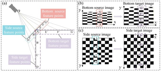
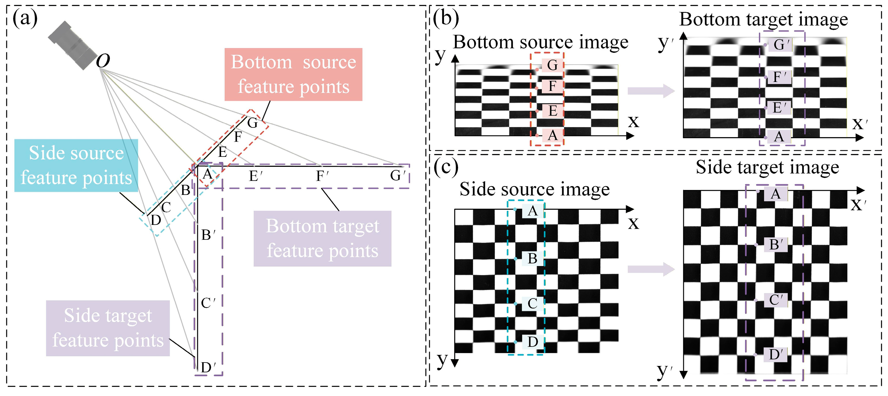
The line-scan imaging system captures 1D contour information of the rotating vessels through sequential row-wise sampling, where each scan line constitutes an independent projective space. Based on the invariance of cross-ratio under projective transformation, a projective correspondence can be established between distorted and ideal scan lines, as illustrated in Figure 4a.
Figure 4.
1D perspective correspondence between the distorted image and the target image. (a) 1D perspective relationship of feature points. (b) Corrected top line-scan image achieving the bottom target image. (c) Corrected side line-scan image obtaining the side target image.
Thus, the projective correspondence between two homologous 1D primitive forms along the same ray bundle can be established based on the cross-ratio invariance:
Since the cross-ratio is an invariant under 1D projective transformation, the point-to-point mapping relationship can be derived accordingly. For a scan line located at position , the distorted coordinate can be modeled using a 1D projective transformation in homogeneous form:
where , , , are the parameters to be estimated.
The projective transformation for each individual scan line can be estimated solely based on local point correspondences, thereby avoiding error accumulation typically encountered in global optimization methods. Accordingly, for a given scan line with pairs of corresponding points , the following objective function is formulated for minimization:
To further improve the accuracy of distortion correction, the Levenberg–Marquardt (L-M) algorithm is employed for nonlinear optimization, aiming to iteratively minimize the reprojection error. The residual function is defined as follows:
Since Equation (7) represents a nonlinear optimization problem, a linear approximation must first be constructed to obtain initial parameter estimates. To initialize the transformation parameters , , , , we formulate a homogeneous constraint matrix by rewriting the 1D projective transformation equation into a linear form, where . Letting , the matrix is constructed as:
The initial parameter vector can then be obtained by solving the homogeneous linear system via Singular Value Decomposition (SVD), followed by normalization to eliminate scale ambiguity.
To enable parameter refinement via the Levenberg–Marquardt (L-M) algorithm, the partial derivatives of the residual function with respect to each parameter are computed to form the Jacobian matrix:
where and represent the influence of parameters and on the residual, while and are associated with the denominator terms and are more sensitive to numerical perturbations.
The L-M algorithm combines the advantages of the Gauss–Newton method and gradient descent. The parameter update rule is given by:
where is the approximate Hessian matrix from the Gauss–Newton formulation, is the damping factor used to adjust the search direction and ensure numerical stability, and is the update step applied to the current parameter estimate .
Under standard regularity conditions—i.e., if the Jacobian is full-rank and is positive definite—the L-M algorithm exhibits superlinear convergence near the optimal solution. This property ensures that the method can rapidly converge when provided with a reasonable initial guess.
Compared to traditional 2D homography estimation, the proposed 1D projective method significantly reduces computational complexity from to . Moreover, since each scan line is corrected independently, the method inherently avoids global error propagation and preserves the spatial consistency of line-scan imaging.
In the same projective space, the mapping results of the sidewall feature points and the bottom feature points after the projective transformation are the same. Figure 4b,c show the target images obtained after correction by perspective projection.
2.2.2. Geometry-Aware Correction of the Bottom Image Based on Polar Mapping
To rectify the bottom line-scan image of the vessels into its original circular geometry, a Cartesian coordinate system is defined with the top-left corner of the image as the origin. In this system, the horizontal axis represents the angular direction centered on the bottom, while the vertical axis corresponds to the radial distance from the center. Each pixel’s angular position is computed from its horizontal coordinate, and the radius is determined by its vertical coordinate, enabling accurate mapping to a polar coordinate system. This transformation ensures precise alignment between the corrected image and the physical geometry of the object.
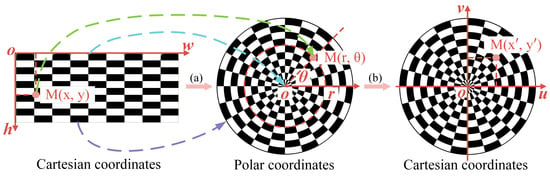
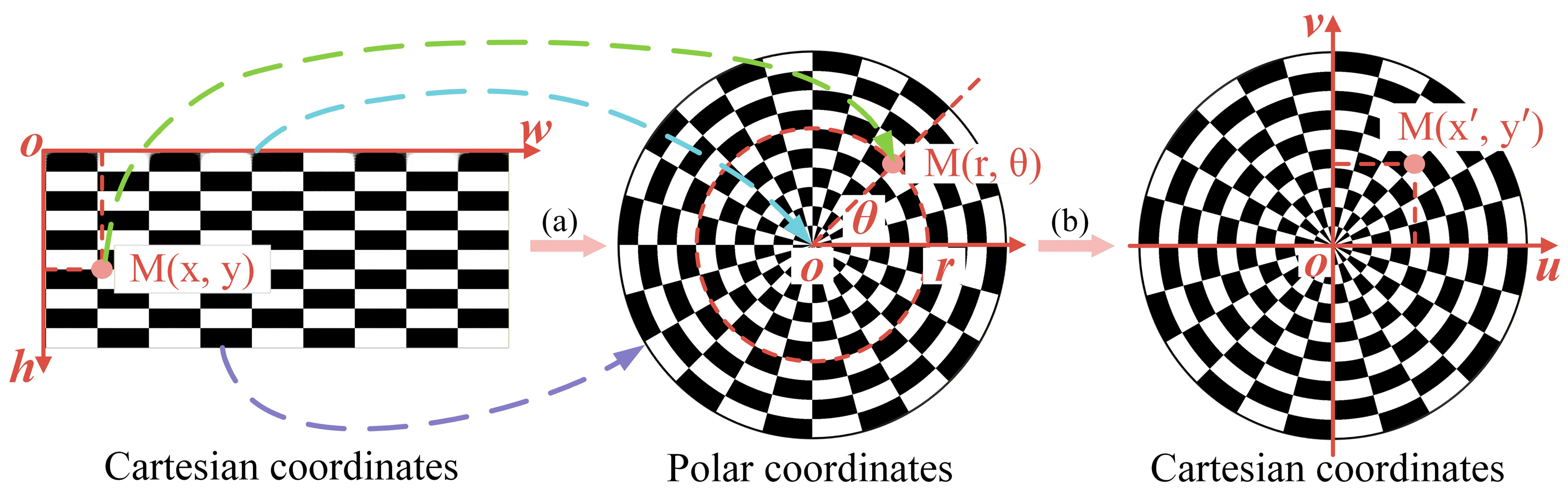
In Figure 5a, let the coordinates of point be . The perspective projection corrected image of the bottom is mapped to polar coordinates as follows:
where is the polar radius, is the polar angle, and is the pixel width of the bottom image.
Figure 5.
The coordinates mapping principles. The green arrow represents the mapping of feature points, the cyan arrow represents the map-ping of the center point, and the purple arrow represents the mapping of the contour. (a) Mapping from Cartesian to polar coordinates, where denotes the image width and denotes the image height. (b) Mapping from polar coordinates to Cartesian coordinates.
Figure 5b depicts the transformation of polar coordinates back to Cartesian coordinates when the origins of both systems coincide. This establishes a one-to-one mapping relationship between corresponding points in the two coordinate systems as follows:
where is the horizontal coordinate of the mapped Cartesian coordinates and is the vertical coordinate.
Coordinate mapping guarantees the faithful restoration of geometric information from the source imagery to the polar coordinate framework while enabling reconstruction of basal structural elements. Furthermore, to mitigate potential informational degradation intrinsic to coordinate transformation procedures, we implement an optimized interpolation kernel. Let the bilinear interpolation result be and the bicubic interpolation result be . The final interpolated output is expressed as:
where is the weighting function of the local interpolation strategy, is the gradient magnitude, and and represent the horizontal and vertical gradient components respectively. denotes the edge detection threshold, and controls the steepness of transition.
3. Results
3.1. Experimental Platform
The experimental imaging system utilized a HIKROBOT MV-CL042-91GC line-scan camera (HIKROBOT, Hangzhou, China) paired with a 35 mm fixed-focus lens (MVL-AF3528M-M42) (HIKROBOT, Hangzhou, China). The camera, which featured sensor pixel pitch of 7 μm, provided an effective spatial sampling resolution of approximately 1420 dpi along the scan direction. Here, a “pixel” refers to the reconstructed image pixel after line-scan acquisition and geometric mapping, rather than the physical sensor pixel on the camera chip. This configuration achieved a circumferential sampling interval of approximately 52.46 μm per pixel, enabling high-precision image acquisition.
The cookware specimens used in the experiments were stainless-steel cylindrical vessels with a height of 100 mm and a bottom radius of 100 mm. During imaging, the vessel was mounted on a precision motorized rotation stage and rotated at a constant angular velocity of 5 rpm to ensure uniform surface sampling.
The complete hardware configuration is illustrated in Figure 6.
Figure 6.
Physical view of single-line-scan imaging device.
3.2. Accuracy Evaluation Method with Correction
3.2.1. Correction Experiment Based on 1D Projective Transformation
To evaluate the effectiveness of the 1D projective transformation, quantitative analysis was conducted on images before and after correction, with a focus on assessing geometric accuracy.
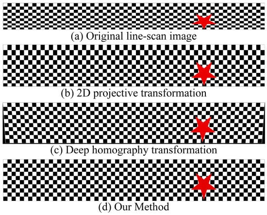
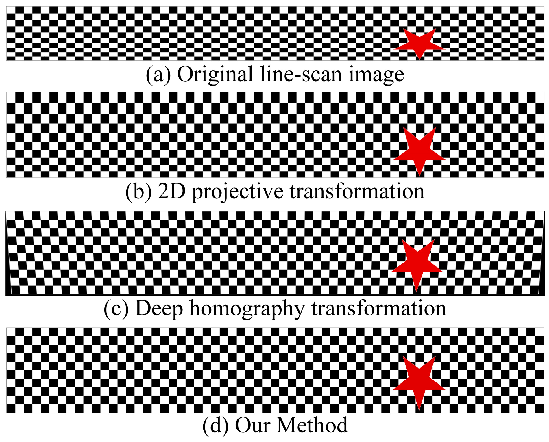
Due to the characteristics of line-scan imaging, the original images are typically stored in a rectangular format, which introduces nonlinear distortion relative to the object’s true physical geometry. To assess correction performance, a checkerboard pattern was used to analyze deformation before and after rectification. As shown in Figure 7, the proposed method was compared with alternative approaches.
Figure 7.
Line-scan image of checkerboard patterned vessels.
Pixel-level displacements of key feature points were computed to quantitatively evaluate the geometric correction performance. For each matched feature point, the localization error was calculated as the Euclidean pixel distance between the distorted and corrected coordinates. The overall geometric error was summarized using Mean Absolute Error (MAE) and Root Mean Square Error (RMSE), while Structural Similarity Index Measure (SSIM) was adopted to assess perceptual structural fidelity. The quantitative comparison of different rectification methods for vessel sidewall imaging is summarized in Table 1, where the proposed method achieves subpixel-level geometric accuracy, significantly outperforming 2D projective and deep learning-based transformations.
Table 1.
Performance Evaluation of Rectification in Vessels Side Imaging Based on 1D Projective Transformation. The symbol ↑ denotes that larger values indicate better performance, while ↓ denotes that smaller values indicate better performance.
In the distorted image, pixel errors were significant. After correction, errors in the y coordinate due to the imaging angle of the line-scan camera were markedly reduced, substantially decreasing deviations from outliers and anomalies. This confirms the algorithm’s effectiveness in reducing overall error.
Table 2 presents a comparative analysis of the vertical spacing between adjacent checkerboard cells before and after angular distortion correction using the proposed 1D projective transformation. Grid spacing refers to the vertical pixel distance between adjacent checkerboard corners along the scanning direction. In the uncorrected images, the cell spacing exhibits a clear decreasing trend along the scanning direction, with errors ranging from 33.89 to 80.08 pixels. After correction, all spacing deviations were reduced to within 0.29 pixels, demonstrating that the proposed geometric correction method achieves subpixel-level accuracy and significantly improves grid uniformity.
Table 2.
Improvement in Checkerboard Grid Spacing Accuracy with 1D Projective Transformation.
To further evaluate the consistency of the results, summary statistics for the eight measured grid intervals are reported in Table 3. Before correction, the mean spacing was 131.01 pixels with a standard deviation of 15.18 pixels, resulting in a coefficient of variation (CV) of 11.59% and a normalized pixel-size uniformity of 88.41%. Following the application of the proposed method, the CV decreased to 0.16%, effectively improving the uniformity to 99.84%. These results demonstrate that the correction framework substantially enhances the geometric fidelity of the reconstructed image.
Table 3.
Pixel-Size Uniformity Evaluation Before and After 1D Projective Transformation. The symbol ↑ denotes that larger values indicate better performance, while ↓ denotes that smaller values indicate better performance.
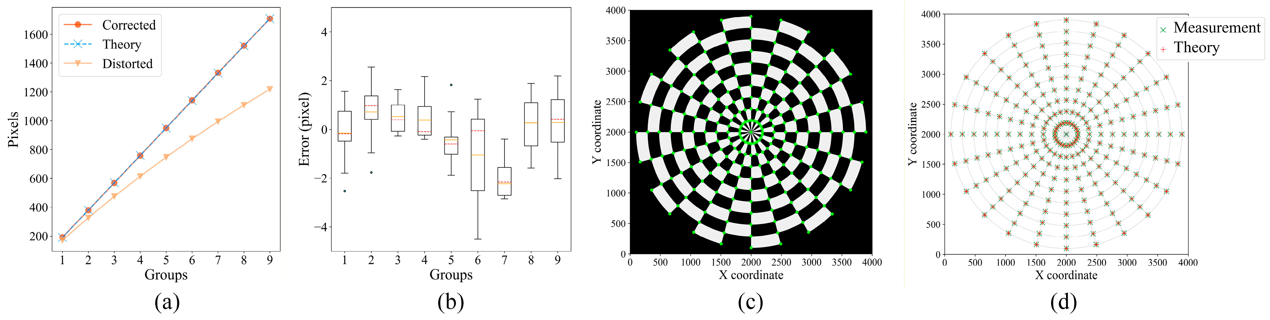
In the experiment, we compared the pixel coordinates of line-scan images for distorted, corrected, and theoretical coordinates, and assessed the error for each set of coordinates, as illustrated in Figure 8.
Figure 8.
Pixel coordinate comparisons. (a) Comparison of the pixel coordinates. (b) Pixel coordinate errors after correction of the proposed method, the dots represent outliers. (c) Feature point map after bottom image correction. (d) Comparison between theory value and measured value after bottom image correction.
The comparison of pixel values between different methods and the ideal values before and after correction is shown in Figure 8. In Figure 8a, the pixel values before correction show a slower growth rate as the group number increases, leading to a larger deviation from the ideal values. This indicates that the experimental results are consistent with the theoretical evaluation, confirming the validity of the evaluation approach. Figure 8b demonstrates that the errors of the proposed method are confined within an acceptable range. However, the average error across different groups shows a layered pattern. The average errors in groups 1 to 5 are relatively consistent, while the averages in groups 6 and 7 are larger. This discrepancy is primarily because the line-scan camera is focused near the junction of the cylindrical surfaces. Consequently, the edge images become defocused, leading to reduced clarity, diminished measurement accuracy, and increased errors in groups 6 and 7.
3.2.2. Correction Experiment Based on Polar Mapping
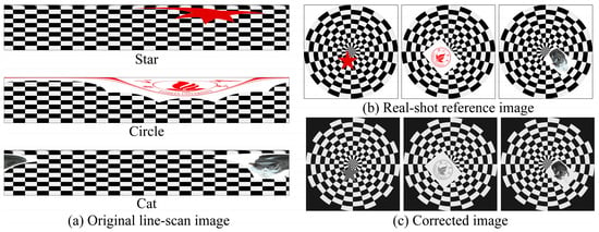
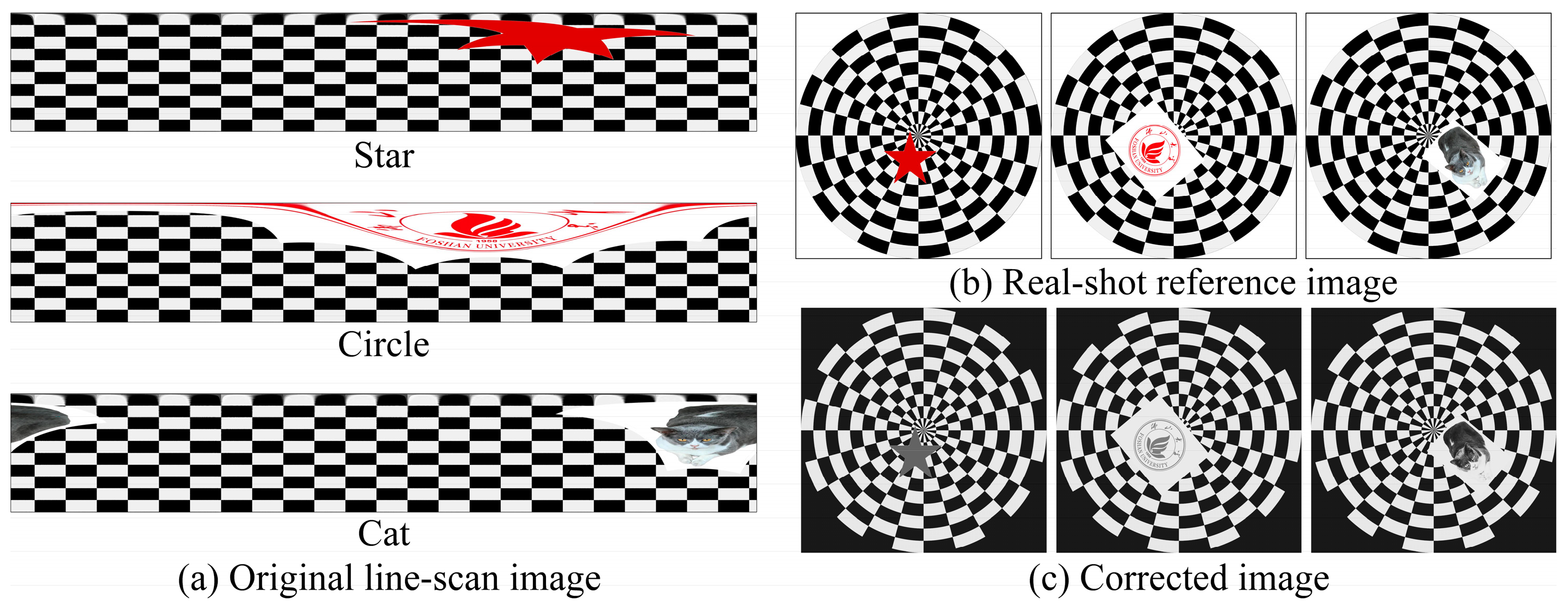
Experimental studies were conducted on the bottom surface line-scan images of vessels to evaluate the effectiveness of the polar mapping method. Figure 9a displays the uncorrected line-scan image, which exhibits significant geometric distortion. Figure 9b shows a reference image of the actual bottom surface, while Figure 9c presents the result after applying the proposed correction method. The comparison clearly demonstrates the improvement in geometric consistency achieved by the proposed approach.
Figure 9.
Comparison of distortion correction results using polar coordinate transformation for the bottom surface line-scan image of a checkerboard-patterned vessels. (a) Original image acquired by the line-scan camera; (b) Reference image of the actual checkerboard bottom surface; (c) Proposed polar mapping method.
To systematically evaluate the performance of polar mapping, this study employs Radial RMSE and Angular Deviation to quantify distortion rectification accuracy, supplemented by SSIM analysis on the grayscale reference image in Figure 9b. Quantitative results are presented in Table 4.
Table 4.
Evaluation of Image Quality and Geometric Accuracy Before and After Polar Correction. The symbol ↑ denotes that larger values indicate better performance, while ↓ denotes that smaller values indicate better performance.
The consistency of the corrected coordinates was evaluated by comparing checkerboard feature points. Harris corner detection was used to obtain the coordinates of each feature point on the chessboard, as illustrated in Figure 8c, identifying a total of 10 × 24 feature points excluding the center. These extracted feature points were then compared with the ideal feature values within the same coordinate system, as shown in Figure 8d. The diagram indicates that the radial spacing between concentric circular patterns increases geometrically with radius, while the angular spacing between feature points within the same circle remains constant, confirming the preservation of radial symmetry after polar correction. This validation confirms that the proposed polar mapping method is effective for geometric correction of the line-scan image of the bottom.
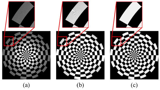
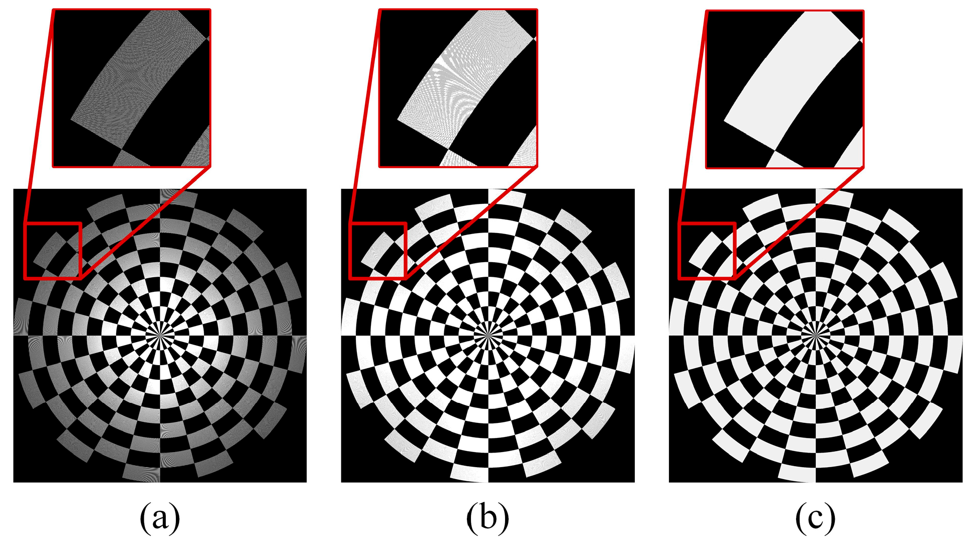
To address potential information loss introduced during coordinate transformation, we further compared the reconstruction quality of different interpolation strategies used in the polar mapping process. As shown in Figure 10, both bilinear and bicubic interpolation methods were applied to remap the image, and their performance was evaluated in terms of detail preservation and edge sharpness. The results conclusively demonstrate that bicubic interpolation achieves optimal performance in maintaining structural continuity and anti-aliasing capability.
Figure 10.
Comparison of interpolation methods after polar mapping. (a) Without interpolation; (b) Bilinear interpolation; (c) Optimized interpolation.
3.2.3. Robust Experiment
To validate the generalization capability and robustness of the proposed geometric correction algorithm in complex industrial scenarios, experiments were conducted on cookware specimens with authentic surface defects, including scratches and stamped patterns. Unlike calibration targets, real cookware surfaces do not provide explicit reference features for direct parameter estimation.
Therefore, the transformation parameters used in this experiment were obtained in advance using a cookware-shaped calibration model with an attached checkerboard pattern on the surface. The checkerboard-enabled model shares the same geometric configuration and imaging setup as the real cookware, allowing reliable extraction of correspondence points and estimation of the 1D projective and polar mapping parameters using the proposed method.
For the sidewall region, the 1D projective transformation parameters for a representative scanline at mid-height were estimated as , , and . This 1D projective transformation can be written as . These parameters were obtained using the proposed calibration procedure and are consistent with the system configuration, including a camera tilt angle of 45° and a working distance of 320 mm. For the base region, geometric correction was performed using the standard polar coordinate mapping described in Section 2.2.2, which requires the bottom image dimensions and the predefined geometric configuration.
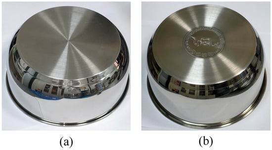
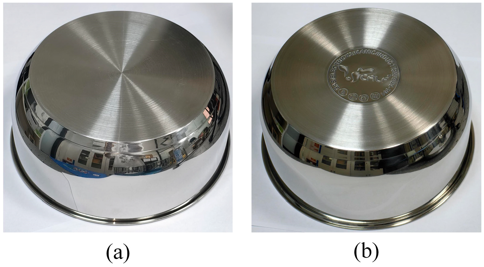
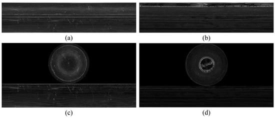
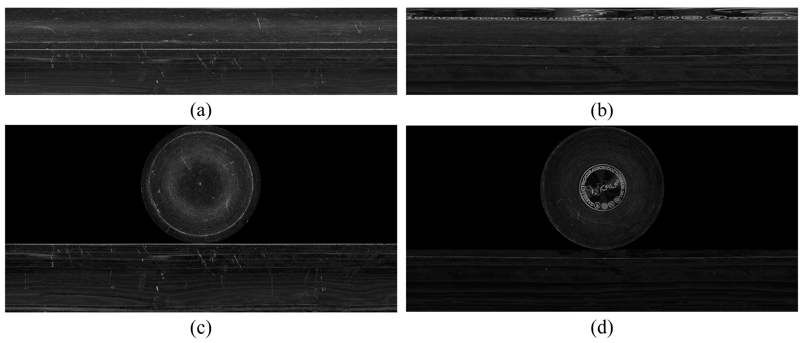
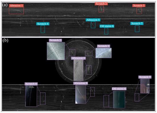
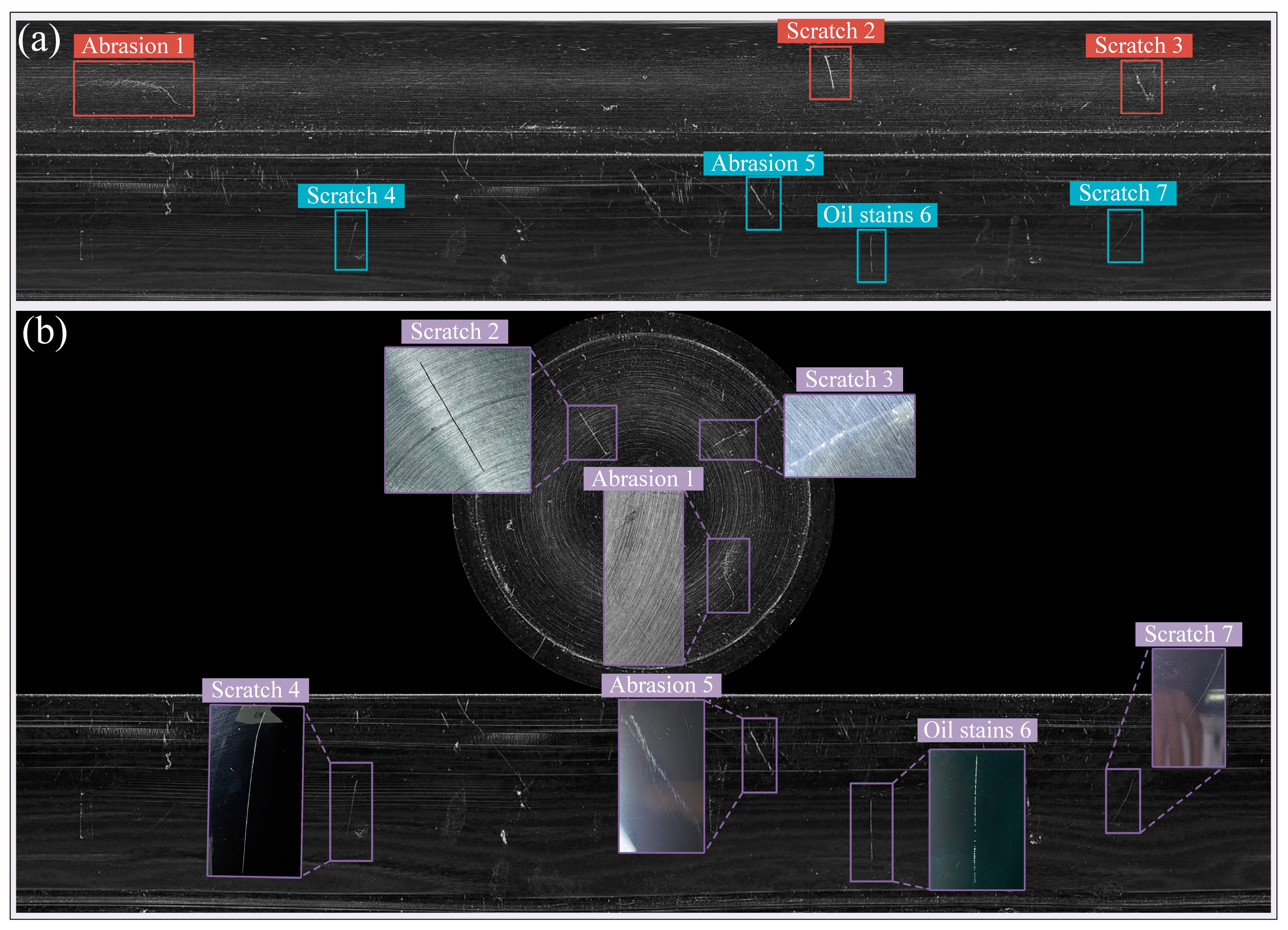
Figure 11 illustrates representative real cookware specimens, which exhibit substantially higher textural complexity and challenging optical effects, such as localized specular reflections and shadowing. Figure 12 presents a visual comparison of the line-scan images before and after geometric correction using the precomputed transformation parameters.
Figure 11.
Real highly reflective cylindrical metallic vessels. (a) Vessels with surface scratches; (b) Vessels with stamped patterns.
Figure 12.
Comparative results of line-scan images before and after geometric correction for different real vessels. (a) Line-scan image of vessels with scratches; (b) Line-scan image of vessels with patterns; (c) Corrected line-scan image of vessels with scratches; (d) Corrected line-scan image of vessels with patterns.
Due to manufacturing tolerances and non-ideal imaging conditions, the physical geometry of real cookware cannot serve as an absolute ground truth reference. Consequently, qualitative evaluation is adopted, focusing on the preservation of geometric consistency and micro-topographic features. As shown in Figure 13, the corrected images exhibit improved structural coherence, consistent scratch orientation, and enhanced edge clarity, demonstrating that the proposed geometric correction framework remains effective and robust when applied to real industrial cookware.
Figure 13.
Before and after correction of the actual highly reflective vessels external surface with defects. (a) Before correction. (b) After correction.
4. Discussion
4.1. Effectiveness of Geometry-Aware Line-Scan Distortion Correction
The experimental results demonstrate that the proposed geometry-aware distortion correction framework effectively restores the geometric structure of line-scan images acquired from cylindrical vessel surfaces. By decomposing the distortion correction process into a 1D projective transformation along the scan direction and a subsequent polar mapping for the bottom surface, the method explicitly exploits the inherent imaging characteristics of line-scan systems.
Quantitative evaluations based on checkerboard calibration patterns showed that the proposed 1D projective transformation significantly reduces geometric deviations along the scan direction, achieving sub-pixel correction accuracy. Compared with conventional two-dimensional projective transformations, the proposed approach preserves geometric consistency while reducing the number of degrees of freedom, which improves numerical stability under limited calibration data. These results validate the rationality of modeling each scan line as an independent 1D projective space.
For bottom surface correction, the polar coordinate transformation successfully restores the intrinsic rotational symmetry of the circular geometry. The substantial reduction in radial RMSE and angular deviation, together with the marked improvement in SSIM values, indicates that the proposed method not only corrects geometric distortions but also preserves structural image information critical for subsequent defect analysis.
4.2. Robustness Under Real Surface Texture and Illumination Variations
Beyond calibration targets, the robustness of the proposed method was further evaluated using real stainless-steel vessel surfaces exhibiting scratches and decorative circular patterns. These images present more complex texture distributions, local reflectance variations, and non-ideal edge structures, which pose challenges for purely data driven or high degree of freedom correction methods.
Experimental results showed that the proposed geometric correction framework remains stable under such conditions. The corrected images maintained consistent radial spacing and angular alignment, while surface defects such as scratches and patterned textures remained visually coherent after transformation. This observation suggests that the proposed method is primarily governed by geometric constraints rather than local intensity or texture features, making it inherently robust to surface appearance variations.
It should be emphasized that the real vessel reference images were captured using an area-scan camera under different illumination conditions and are therefore not treated as geometric ground truth. Instead, they serve as qualitative visual references to assess the structural plausibility and defect visibility after correction. This design choice avoids unfair comparisons while still demonstrating the practical applicability of the proposed approach in real industrial scenarios.
4.3. Sensitivity Analysis and Industrial Robustness
The sensitivity of the proposed method to parameter variations was analyzed to evaluate its robustness under industrial conditions. Regarding synchronization accuracy, deviations in the circumferential direction primarily result in uniform angular scaling, which can be effectively eliminated through real-time encoder feedback synchronization. In the absence of encoder feedback, such deviations can be compensated by post-processing rescaling based on the known rotational speed error.
For the 1D projective transformation, a minimum of four corresponding point pairs per scanline is required to estimate the transformation parameters. To evaluate sensitivity to correspondence errors and image noise, Gaussian noise with a standard deviation of σ = 0.5 pixels was added to the calibration points. Under this condition, the RMSE increased by only 0.08 pixels, indicating that the proposed method exhibits strong robustness to minor correspondence inaccuracies caused by mechanical vibration or alignment drift.
It should be noted that when the number of valid correspondences approaches the theoretical minimum or when noise levels significantly exceed typical industrial conditions, the estimation accuracy may degrade. Nevertheless, under practical operating conditions, the proposed method maintains stable performance.
4.4. The Generality for Different Cylinder Dimensions
The proposed framework demonstrates strong generality across cylindrical vessels with diameters ranging from 50 to 400 mm, primarily limited by the camera field of view and working distance. In addition, the method remains applicable to a wide range of aspect ratios (height-to-diameter ratios from 0.3 to 2.0), which covers most industrial cookware and thin-walled cylindrical components.
The analytic 1D projective model inherently adapts to different cylinder radii through the underlying imaging geometry, without requiring recalibration, provided that the camera pose remains unchanged.
Regarding potential extensions, the current framework assumes circular symmetry and is therefore directly applicable to cylindrical geometries. Extension to more complex shapes, such as conical surfaces or components with elliptical cross-sections, would require replacing the linear projective model with higher-order (e.g., quadratic) transformations or adopting elliptical coordinate mappings. These extensions fall beyond the scope of the present work but preserve the overall computational efficiency of the proposed approach, at the expense of introducing additional geometric parameters.
4.5. Limitations and Future Work
From an industrial perspective, the proposed method offers a practical and lightweight solution for distortion correction in line-scan inspection systems. Unlike deep learning-based approaches that require large-scale annotated datasets and extensive retraining, the proposed framework relies on explicit geometric modeling and can be readily deployed in real production environments with minimal calibration effort.
However, the proposed method is not applicable to: (1) strongly non-cylindrical or free-form surfaces lacking rotational symmetry; (2) transparent or highly translucent materials where dark-field scattering models fail; or (3) applications requiring real-time correction rates above 100 Hz.
Despite the encouraging results, several limitations remain:
- The current experiments were conducted using a fixed focal length lens and a limited number of cookware samples. Although the proposed method demonstrates robustness across different surface textures, its performance under varying camera poses, lens parameters, or non-cylindrical geometries requires further investigation;
- The assumption of scan-line independence, which enables the reduction to a 1D projective model, may be violated in extreme cases involving significant defocus, mechanical vibration, or severe illumination non-uniformity. Defocus effects near peripheral regions stem from depth-of-field limitations when imaging curved surfaces with fixed-focus optics. Mitigation strategies in defocus include multi-focus fusion from dual scans and increased f-number (f/11–f/16) with compensated lighting. Future work will explore adaptive models that incorporate limited inter-line coupling while preserving computational efficiency;
- Integrating the proposed geometric correction framework with downstream defect detection algorithms presents a promising direction. By providing geometrically consistent and distortion-free images, the method is expected to improve the accuracy and reliability of defect segmentation and quantitative inspection in high-reflective industrial components.
5. Conclusions
This study presents a single-line-scan imaging system tailored to highly reflective cylindrical surfaces and develops a corresponding distortion correction algorithm. Geometric constraints involving the vessel dimensions, turntable rotation speed, and camera line frequency are formulated to ensure complete single-pass surface acquisition. A 1D projective transformation is applied to rectify perspective distortion along the cylindrical sidewall, while polar mapping is employed to restore geometric consistency on the circular base.
Experimental results confirm that the proposed algorithm effectively eliminates shape deformation and pixel-size nonuniformity caused by line-scan imaging characteristics, resulting in accurate geometric reconstruction of the cylindrical surface. Nevertheless, due to the complex geometry, defocus occurs near the peripheral regions of the image, leading to local fluctuations in measurement precision. Future work will focus on enhancing the acquisition system to improve edge-region imaging and further increase correction accuracy.
Author Contributions
Conceptualization, J.Q. and J.Z.; methodology, J.Q.; software, J.Q. and J.Z.; validation, J.Z., Y.H. and X.C.; formal analysis, J.Q. and J.Z.; investigation, J.Q. and X.C.; resources, J.Z. and Y.H.; data curation, J.Z. and Y.H.; writing—original draft preparation, J.Z.; writing—review and editing, J.Q., X.C., J.Y., G.L. and H.T.; visualization, J.Z. and X.C.; supervision, X.C.; project administration, J.Q., J.Z. and X.C.; funding acquisition, J.Q. and X.C. All authors have read and agreed to the published version of the manuscript.
Funding
This research was funded by National Natural Science Foundation of China, grant number 62201151; Open Research Fund of Guangdong Special Equipment Safety Science and Technology Collaborative Innovation Center, grant number 2025SEKF-01; Shenzhen Major Science and Technology Projects, grant number KJZD20231023092302006.
Data Availability Statement
The original contributions presented in this study are included in the article. Further inquiries can be directed to the corresponding authors.
Acknowledgments
The authors express gratitude to the editors and the reviewers for their constructive and helpful review comments.
Conflicts of Interest
Author Guojie Lu was employed by Shenzhen United Winners Laser Co., Ltd. The remaining authors declare that the research was conducted in the absence of any commercial or financial relationships that could be construed as a potential conflict of interest.
References
- Ren, R.; Ma, X.; Yue, H.; Yang, F.; Lu, Y. Stiffness Enhancement Methods for Thin-Walled Aircraft Structures: A Review. Thin-Walled Struct. 2024, 201, 111995. [Google Scholar] [CrossRef] [Scilit]
- Liu, Z.; Hu, Y.; Zhang, M.; Zhang, W.; Wang, J.; Lei, W.; Wang, C. Surface Morphology Evolution Mechanisms of Pulse Laser Polishing Mold Steel. Int. J. Mech. Sci. 2024, 269, 109039. [Google Scholar] [CrossRef] [Scilit]
- Ge, P.; Wang, H.; Wang, Y.; Wang, B. Calibration of Ring Multicamera System With Transparent Target for Panoramic Measurement. IEEE Sens. J. 2022, 22, 23154–23164. [Google Scholar] [CrossRef] [Scilit]
- Pan, N.; Gao, S.; Bai, J.; Wang, K. Design of a Compact Triple-Channel Panoramic Stereo Imaging System. Opt. Express 2023, 31, 17731–17745. [Google Scholar] [CrossRef] [Scilit] [PubMed]
- Wang, S.; Tong, Y.; Shang, X.; Zhang, Z. Hierarchical Viewpoint Planning for Complex Surfaces in Industrial Product Inspection. IEEE/ASME Trans. Mechatron. 2023, 29, 3289–3299. [Google Scholar] [CrossRef] [Scilit]
- Yang, H.; Fang, C.; Zhang, X. Improvement of Calibration Method for Multi-Camera Line Structured Light Vision System. Appl. Phys. B 2022, 128, 116. [Google Scholar] [CrossRef] [Scilit]
- Rouwane, A.; Texier, D.; Périé, J.-N.; Dufour, J.-E.; Stinville, J.-C.; Passieux, J.-C. High Resolution and Large Field of View Imaging Using a Stitching Procedure Coupled with Distortion Corrections. Opt. Laser Technol. 2024, 177, 111165. [Google Scholar] [CrossRef] [Scilit]
- Lou, W.; Cao, P.; Wang, F.; Jiang, J.; Yang, Y. Error Analysis and Measurement Methods of Curved Optical Element Surface Defects Dark-Field Imaging Inspection System Based on Multi-Axis Kinematics. Opt. Commun. 2022, 521, 128601. [Google Scholar] [CrossRef] [Scilit]
- Qiao, J.; Sun, C.; Cheng, X.; Yang, J.; Chen, N. Stainless Steel Cylindrical Pot Outer Surface Defect Detection Method Based on Cascade Neural Network. Meas. Sci. Technol. 2024, 35, 036201. [Google Scholar] [CrossRef] [Scilit]
- Gao, W.; Zhang, J.; Liu, K.; Li, L.; Wang, M.; Ma, B. Spherical Image Acquisition and Defect Detection of Nuclear Fuel Based on the Line Scan. Measurement 2024, 229, 114371. [Google Scholar] [CrossRef] [Scilit]
- Tao, X.; Zhang, Z.; Zhang, F.; Xu, D. A Novel and Effective Surface Flaw Inspection Instrument for Large-Aperture Optical Elements. IEEE Trans. Instrum. Meas. 2015, 64, 2530–2540. [Google Scholar] [CrossRef] [Scilit]
- Chen, G.; Liang, Q.; Zhong, W.; Gao, X.; Cui, F. Homography-Based Measurement of Bridge Vibration Using UAV and DIC Method. Measurement 2021, 170, 108683. [Google Scholar] [CrossRef] [Scilit]
- Peng, H.; Sun, C.; Wang, P. The Design and Implementation of the Lookup Table in Distortion Correction for the Optical System. IEEE Access 2023, 11, 44335–44342. [Google Scholar] [CrossRef] [Scilit]
- Zhang, Y.; Fan, J.; Liu, Y.; Mao, X. Fast Correction for Geometric Distortion in PFA Wavefront Curvature Compensation. IEEE Trans. Comput. Imaging 2026, 12, 60–72. [Google Scholar] [CrossRef] [Scilit]
- Zhang, J.; Lian, L.; Yang, P.; Sun, M.; Zhang, Y.; Xiao, Y. Geometric Distortion Correction of Oblique Incidence Laser Interferometer System for Helical Surface Topography Measurement. Opt. Lasers Eng. 2025, 194, 109175. [Google Scholar] [CrossRef] [Scilit]
- Li, H.; Wu, X.; Chen, Q.; Xiang, Q. Foreground and Text-Lines Aware Document Image Rectification. In Proceedings of the 2023 IEEE/CVF International Conference on Computer Vision (ICCV); IEEE: New York, NY, USA, 2023; pp. 19517–19526. [Google Scholar] [CrossRef] [Scilit]
- Yu, F.; Xie, Y.; Wu, L.; Wen, Y.; Wang, G.; Ren, S.; Chen, X.; Mao, J.; Li, W. DocReal: Robust Document Dewarping of Real-Life Images via Attention-Enhanced Control Point Prediction. In Proceedings of the 2024 IEEE/CVF Winter Conference on Applications of Computer Vision (WACV); IEEE: New York, NY, USA, 2024; pp. 654–663. [Google Scholar] [CrossRef] [Scilit]
- Liu, H.; Li, Y.; Ma, Z.; Wang, C. Recognition and Calibration of Rail Profile Under Affine-Distortion-Based Point Set Mapping. IEEE Trans. Instrum. Meas. 2017, 66, 131–140. [Google Scholar] [CrossRef] [Scilit]
- Cheng, X.; Zhong, B.; Tan, H.; Qiao, J.; Yang, J.; Li, X. Correction for Geometric Distortion in the Flattened Representation of Pipeline External Surface. Eng. Res. Express 2024, 6, 025218. [Google Scholar] [CrossRef] [Scilit]
- Chi, B.; Wang, F.; Guo, Q.; Zhang, Y.; Ju, C.; Yuan, W. An Adaptive and Efficient Affine Transformation-Based Subdivision Method for Evaluation of Nearly Singular Integrals. Eng. Anal. Bound. Elem. 2023, 156, 519–536. [Google Scholar] [CrossRef] [Scilit]
- Sihombing, D.P.; Nugroho, H.A.; Wibirama, S. Perspective Rectification in Vehicle Number Plate Recognition Using 2D-2D Transformation of Planar Homography. In Proceedings of the 2015 International Conference on Science in Information Technology (ICSITech); IEEE: New York, NY, USA, 2015; pp. 237–240. [Google Scholar] [CrossRef] [Scilit]
- Cao, S.-Y.; Zhang, R.; Luo, L.; Yu, B.; Sheng, Z.; Li, J.; Shen, H.-L. Recurrent Homography Estimation Using Homography-Guided Image Warping and Focus Transformer. In Proceedings of the 2023 IEEE/CVF Conference on Computer Vision and Pattern Recognition (CVPR); IEEE: Vancouver, BC, Canada, 2023; pp. 9833–9842. [Google Scholar] [CrossRef] [Scilit]
- Lu, Y.; Wang, H.; Wei, W. Mobile Localization of Multiple Construction Hazards Based on Panoramic Vision and Spatial Transformation. Eng. Appl. Artif. Intell. 2026, 165, 113427. [Google Scholar] [CrossRef] [Scilit]
- Pei, S.-C.; Hsiao, Y.-Z. Spatial Affine Transformations of Images by Using Fractional Shift Fourier Transform. In Proceedings of the 2015 IEEE International Symposium on Circuits and Systems (ISCAS); IEEE: Lisbon, Portugal, 2015; pp. 1586–1589. [Google Scholar] [CrossRef] [Scilit]
- Moutsis, S.N.; Tsintotas, K.A.; Kansizoglou, I.; Gasteratos, A. P-RoPE: A Polar-Based Rotary Position Embedding for Polar Transformed Images in Rotation-Invariant Tasks. Pattern Recognit. Lett. 2026, 200, 23–29. [Google Scholar] [CrossRef] [Scilit]
- Yang, Z.; Yang, L.; Chen, G.; Yap, P.-T. Improved Polar Complex Exponential Transform for Robust Local Image Description. Pattern Recognit. 2023, 143, 109786. [Google Scholar] [CrossRef] [Scilit]
- Yang, L.; Nie, B.; Wei, L.; Xu, L.; Jing, J.; Zhou, J.; He, X.; Feng, L.; Li, Y. Distortion Correction Based on Off-Axis Schwarzschild Two-Mirror Hyperspectral Imager. Opt. Express 2021, 29, 22944. [Google Scholar] [CrossRef] [Scilit]
- Zhang, Y.; Chu, C.H.H. One-Dimensional Mapping for Estimating Projective Transformations. IEEE Trans. Image Process. 2010, 19, 3049–3058. [Google Scholar] [CrossRef] [Scilit] [PubMed]
- Wang, C.; Luo, W.; Niu, M.; Li, J.; Song, K. A Binocular Color Line-Scanning Stereo Vision System for Heavy Rail Surface Detection and Correction Method of Motion Distortion. J. Imaging 2024, 10, 144. [Google Scholar] [CrossRef] [Scilit] [PubMed]
- Yoon, S.; Son, Y.; Oh, S.; Han, S. A Distortion Model of Laser Sheet for a Laser Line Scanner With Large Fan Angle. IEEE Trans. Ind. Electron. 2020, 67, 6986–6995. [Google Scholar] [CrossRef] [Scilit]
- Li, Y.; Gao, F.; Xu, Y.; Hill, M.; Ni, Y.; Gao, N.; Meng, Z.; Zhang, Z.; Jiang, X. Review of System Modeling and Calibration Technologies for Specular/Diffuse Composite Surface Metrology. Opt. Lasers Eng. 2026, 201, 109662. [Google Scholar] [CrossRef] [Scilit]
- Feng, W.; Liu, H.; Zhao, D.; Xu, X. Research on Defect Detection Method for High-Reflective-Metal Surface Based on High Dynamic Range Imaging. Optik 2020, 206, 164349. [Google Scholar] [CrossRef] [Scilit]
- Wang, S.; Sun, H.; Hu, X.; Zou, S.; Guo, S.; Wang, H.; Sun, F.; Cheng, X.; Zhang, J.; Liu, D. Scanning Strategy for Surface Defects Evaluation of Large Fine Optical Components. Opt. Laser Technol. 2022, 156, 108473. [Google Scholar] [CrossRef] [Scilit]

Disclaimer/Publisher’s Note: The statements, opinions and data contained in all publications are solely those of the individual author(s) and contributor(s) and not of MDPI and/or the editor(s). MDPI and/or the editor(s) disclaim responsibility for any injury to people or property resulting from any ideas, methods, instructions or products referred to in the content. |
© 2026 by the authors. Licensee MDPI, Basel, Switzerland. This article is an open access article distributed under the terms and conditions of the Creative Commons Attribution (CC BY) license.