


Abstract
Programmable metasurfaces provide transformative platforms for wavefront manipulation and beamforming. However, current works still highly rely on manual control (e.g., pre-specified look-up table rules), which limits their applications for intelligent wireless communications. Here, we propose a large language model (LLM)-assisted pattern-switching technology based on an amplitude–phase-controllable metasurface, which can reason the working states of the metasurface according to semantics and realize the expected beam-steering and beamforming functions. The proposed meta-atom integrates two types of diodes (PIN and varactor diodes), providing independent amplitude–phase control and 360° full-phase coverage. The LLM can conduct the dimensionality reduction in high-level semantics into structured electromagnetic targets and map them to the metasurfaces, controlling the sequences of the metasurface and thereby realizing the desired pattern-switching function. The autonomy refers to task-level autonomous execution after a high-level user requirement is specified, including automatic state searching, threshold-based performance evaluation, and iterative reconfiguration. To verify the feasibility of the proposed strategy, we fabricated an amplitude–phase-controllable metasurface and conducted LLM-assisted functional measurements. The measured results agree well with the expected ones. The proposed method holds great potential for future human–machine interfaces in wireless communications.
1. Introduction
In the past decade, programmable metasurfaces have shown great potential for applications in manipulation and beamforming [1,2,3,4,5]. By controlling the states of active elements loaded in metasurfaces, the electromagnetic (EM) responses (including amplitude, phase, frequency, etc.) can be dynamically reconfigured, thereby realizing phase-controlled beam scanning, anomalous reflection/refraction, and radar cross-section manipulation [2,3,4,5,6,7]. However, to adapt complex EM environments and achieve continual EM function switching, metasurfaces need to constantly update the controlling sequences manually [8], thereby resulting in inefficient and error-prone non-autonomous regulation, which limits their applications for intelligent wireless communications.
Previous metasurface studies primarily focused on unidirectional and open-loop control of EM parameters [9,10,11,12,13,14]. However, unidirectional control methods lack autonomous perception of the EM environment [15,16,17], which limits their capability in EM environment sensing and precise real-time control. To this end, reference [18] proposed a smart metasurface which can sense EM environments by integrating additional sensors; the working principle is to achieve controllable beam steering by a feedback algorithm software. Further, an adaptively programmable metasurface can sense and manipulate EM waves and signals via an optimization algorithm, which required no external environmental input [19]. Despite these significant advancements [20,21,22], these works depended on precision sensors, and the initiative in these tasks requires triggering-related instructions, which strictly limits their autonomy and intelligence. Subsequently, a nanostructured birefringent metasurface was proposed to enable low-latency phase diversity wavefront sensing via machine learning, which can extend the range and accuracy of FSO systems [23]. However, this work relies on external human intervention, pre-specified look-up-table rules, and machine learning to meet environmental feedback and user requirements. Currently, LLMs have been widely applied in semantic reasoning, task understanding, and high-level decision-making [24,25,26]. Users do not need to directly specify low-level EM-control parameters, as the natural language processing capability of LLMs provides a flexible interface capable of interpreting a wide range of user-defined tasks.
To address this need, we propose an LLM-assisted pattern-switching technology based on an amplitude–phase-controllable metasurface. The LLM serves as a high-level semantic interface, which conducts dimensionality reduction for users’ natural language tasks and controls the EM behaviors of metasurfaces based on the reduced-dimensional mechanical instructions. It should be emphasized that natural language interaction and autonomous closed-loop control play different roles in this proposed LLM-assisted pattern-switching technology. Firstly, the LLM interprets the user’s high-level intention and converts it into explicit EM-control targets. Secondly, the LLM-assisted architecture automatically searches for the physically realizable control state and then evaluates the obtained simulation or experimental response according to predefined performance thresholds. Lastly, the LLM-assisted architecture determines whether further adjustment is required. During this closed-loop process, the user can monitor the execution status and intervene or refine the requirement when necessary. Meanwhile, low-level state searching, evaluation, and reconfiguration are performed automatically by this LLM-assisted pattern-switching technology. In this paper, we utilize an amplitude–phase-controllable reflective metasurface to realize precise and efficient pattern switching; the designed meta-atoms integrate PIN diodes and varactor diodes, which accomplishes 10 dB amplitude manipulation and 360° full-phase coverage. By mapping the LLM-processed mechanical instructions to the bias sequences of the proposed metasurface, the final beam-pointing control and sidelobe optimization functions can be realized. We manufactured the metasurface sample and developed a metasurface-based LLM semantic controlling system and demonstrated the feasibility of the proposed LLM-assisted architecture by measuring several of the expected sidelobe-reduced patterns. The main contribution of this work is the integration of LLM-based semantic task interpretation and a physically constrained amplitude–phase control framework, thereby connecting high-level user requirements to executable metasurface states. Our method provides a feasible route for future intelligent wireless communications and human–machine-interactive EM systems.
2. Methods
2.1. LLM-Assisted Intelligent Pattern-Switching Decision Framework
Current programmable metasurfaces still lack autonomous intelligence, and their working states mainly rely on manual setting, look-up table calling, or pre-specified rule switching. For a single-beam deflection or fixed pattern-switching task, these methods can satisfy the basic requirements. However, in dynamic wireless communications and complex EM environments, users usually do not provide specific diode bias voltages or coding sequences but give high-level semantic requirements, such as “steer the reflected beam to a desired direction”, “reduce the sidelobe while maintaining the main-beam direction”, or “rapidly switch among different beam patterns”. If task parsing, amplitude–phase distribution calculation, bias matching, and control instruction loading are still performed manually, the real-time response capability and intelligence level of the metasurfaces will be significantly limited.
To address this issue, in this work we construct an LLM-assisted intelligent pattern-switching decision framework based on an amplitude–phase-controllable metasurface, as shown in Figure 1. This framework does not use the LLM to replace EM simulation or physical modeling. Instead, it serves as a high-level semantic-understanding and decision-making interface. LLM conducts semantic parsing, task decomposition, and constraint checking for the natural language tasks input by users, and then reduces the abstract requirements into explicit EM-control targets, including the target beam direction, working mode, sidelobe constraint, amplitude distribution type, and phase gradient. For ordinary beam-deflection tasks, the system generates a uniform-amplitude distribution and a linear phase gradient. For low-sidelobe beamforming tasks, an aperture-weighting distribution, such as a Taylor amplitude tapering, is further introduced, thereby realizing beam-pointing control and sidelobe suppression simultaneously. In the present prototype, the uniform-amplitude distribution, linear phase gradient, and Taylor tapering are predefined EM synthesis rules rather than beamforming strategies autonomously created by the LLM. Here, the autonomy refers to the subsequent task-level execution: after the user specifies a high-level objective, the framework automatically performs semantic task interpretation, feasible-state searching, threshold-based performance evaluation, and iterative reconfiguration within the predefined EM rules and calibrated physical-state space. In other words, the LLM serves as a high-level semantic-understanding and decision-making interface that connects user-defined EM tasks with the low-level physical control of the metasurface. Following the structured prompt-engineering and task-decomposition strategy, the LLM operates under a fixed domain-specific prompt that defines its system role, supported EM functions, task-parsing rules, output format, physical constraints, and exception-handling rules. Representative few-shot demonstrations are included in the prompt to standardize semantic interpretation and task decomposition. These examples are used to illustrate the decision rules rather than to define a finite set of keyword-triggered commands. Therefore, user instructions expressed with different wording or previously unseen linguistic forms can still be interpreted according to their semantic intent.
Figure 1.
Conceptual illustration of the LLM-controlled amplitude–phase-independent programmable metasurface. (a) Workflow of the LLM-assisted autonomous metasurface with performance feedback. (b) Schematic of the experimental verification in a microwave anechoic chamber.
For each natural language instruction, the LLM converts the user intent into a structured EM-task representation containing the requested function, target beam direction, amplitude-distribution type, phase distribution type, and sidelobe-control requirement. The LLM therefore acts as a semantic reasoning and task-decomposition layer rather than as an unconstrained generator of low-level hardware parameters.
To clearly distinguish the LLM role from the control modules, the LLM is responsible only for high-level semantic interpretation, intent abstraction, task decomposition, and structured generation. It does not perform EM simulation, aperture synthesis, bias-state optimization, physical-database searching, or FPGA-sequence generation. Once the structured task has been obtained, deterministic modules generate the required amplitude–phase distribution according to the corresponding EM-control rule. Meanwhile, it searches the calibrated database using Equations (1)–(4), selects the physically realizable bias states, and generates the FPGA control sequence. This architecture therefore explicitly separates the semantic reasoning layer and the physical execution layer in our proposed framework.
Accordingly, the methodological role of the LLM is different from conventional keyword- or template-based semantic parsing. A rule-based parser normally requires the explicit enumeration of command patterns and predefined linguistic mappings. By contrast, under the specific prompt and few-shot examples, the LLM can map semantically equivalent but differently worded instructions into the same structured EM task representation. It can also decompose compound requirements and request clarification when critical information is missing. Thus, the LLM provides semantic generalization and task-level abstraction beyond simple interface automation, while the deterministic controller preserves reproducibility and physical consistency.
The natural language interface represents only the high-level interaction layer of the proposed system. After the user intent has been converted into explicit EM targets, the subsequent execution forms an autonomous feedback loop. Specifically, the LLM-assisted architecture searches the pre-calibrated physical database for a state that best meets the target amplitude–phase distribution, generates the corresponding FPGA control sequence, and evaluates the obtained simulation or experimental response according to predefined performance thresholds. If the response does not satisfy the target within the prescribed tolerance, the architecture continues the state-searching and adjustment process until an acceptable solution is obtained or no feasible state remains. During this process, the user can monitor the intermediate status and intervene or refine the instruction when it is necessary. In this way, the proposed framework combines natural language interaction with autonomous closed-loop EM control while retaining user supervision for flexible human–machine interaction.
In our experiment, the feedback is returned to the LLM-assisted host program rather than being treated only as a result displayed to the user. After each metasurface state is loaded through the FPGA, the receiving antenna scans the scattered field and the measured radiation pattern is processed to extract task-related performance metrics, such as the achieved main-beam direction and sidelobe level. These measured metrics are then compared with the target values and predefined tolerances. If the measured response satisfies the acceptance criterion, the current state is retained. Otherwise, the measured deviation is returned to the decision framework, and the database-constrained state-searching module selects another feasible amplitude–phase state. The corresponding FPGA control sequence is then reloaded and the metasurface response is measured again. This measurement–evaluation–state-update cycle continues until the target tolerance is satisfied or no further feasible state is available.
After obtaining the target amplitude–phase distribution, the system maps it to physically executable metasurface states through the pre-calibrated amplitude–phase response database. The LLM does not directly generate PIN-diode bias currents, varactor-diode bias voltages, equivalent circuit parameters, or arbitrary FPGA-level control values. Instead, the target amplitude–phase distribution generated from the interpreted task is passed to the deterministic database-matching procedure described by Equations (1)–(4). In this work, the amplitude–phase response database of the meta-atom is established through full-wave simulation and experimental calibration, which records the reflection amplitude and reflection phase for different combinations of PIN-diode bias current and varactor-diode reverse-bias voltage. The PIN diode is mainly used to control the reflection amplitude, whereas the varactor diode is mainly used to control the reflection phase. If an exact calibrated state corresponding to the target amplitude–phase response is available, the associated physical bias state is selected directly. If no exact state is available, all calibrated states are searched and the physically realizable state that minimizes the amplitude–phase matching error is selected. The selected bias states are subsequently converted into FPGA-executable multichannel control sequences. Because the amplitude and phase responses are partially coupled in practical meta-atoms, a database-assisted joint matching strategy is adopted. Specifically, the element state that best matches the target amplitude–phase response is selected from all available bias combinations, then converted into multichannel control instructions executable by the field-programmable gate array (FPGA).
The relevant database calibration methods and descriptive Equation are described below. The diode bias value is determined from a pre-calibrated physical database, which is expressed by Equation (1):
In Equation (1), A represents amplitude, represents phase, represents PIN diode bias current, represents reverse-bias voltage of a varactor diode, and D represents pre-calibrated physical database. is the reflection amplitude corresponding to the metasurface unit cell under given and conditions. is the corresponding reflection phase under the same bias combination.
The amplitude–phase matching problem is then defined as
Here, and control the amplitude error weight and phase error weight, respectively. I: A candidate PIN diode bias current during the database search process. V: A candidate varactor-diode bias voltage during the database search process. J (I, V): The composite error function representing the discrepancy between a candidate bias combination and the target amplitude–phase state. The arg min: Refers not to finding the minimum error value itself, but to identifying the specific set of I and V values that minimize J (I, V). is the optimal PIN bias current obtained through final matching. is the optimal varactor bias voltage obtained through final matching. The physical meaning of Equation (2) is as follows: Iterate through the available bias combinations in the pre-calibration database to find the set of PIN diode currents and varactor-diode voltages that most closely match the target amplitude and phase. is the target reflection amplitude required for the n-th metasurface unit. is the target reflection phase required for the n-th metasurface unit.
Because the phase response is 2π-periodic, a wrapped phase error is used, as defined in Equation (4):
Physical realizability is therefore enforced by the pre-calibrated amplitude–phase database and the deterministic matching algorithm rather than by unconstrained LLM generation. For any requested amplitude–phase state, only bias combinations contained in the calibrated physical database are eligible for hardware execution. If the requested target does not exactly correspond to an available database state, the matching algorithm searches for the feasible state with the minimum value of . If the resulting mismatch satisfies the predefined acceptance criterion, the nearest feasible calibrated state is executed and the approximation is reported to the user. Otherwise, the requested state is marked as unavailable and no FPGA control sequence is issued. Thus, an LLM-generated semantic target cannot directly bypass the physical constraints of the metasurface hardware.
The framework also explicitly handles ambiguous, incomplete, and out-of-distribution instructions (for details, refer to Appendix A). If essential task information is missing or the user intent is ambiguous, the LLM does not infer the missing critical parameters arbitrarily. Instead, it returns a clarification request and asks the user to provide the missing information before execution. If the requested EM function is outside the calibrated capability of the current metasurface, the instruction is rejected and an unsupported-task message is returned. For a physically meaningful task whose exact target state is absent from the calibrated database, the downstream matching module searches for the nearest feasible state according to the defined amplitude–phase error function. If no acceptable state exists, the system returns an unavailable status. In all cases, no unvalidated hardware state is applied to the metasurface.
Firstly, the LLM-assisted architecture autonomously finds the pre-calibrated database for the control sequence that best satisfies the user-defined functional requirement. Secondly, the LLM-assisted architecture will evaluate whether the resulting simulation or experimental response falls within the predefined performance tolerance. If the prescribed criterion is not satisfied, the system continues the state-searching and adjustment process. Finally, this autonomous state selection and threshold-based result evaluation constitute the closed-loop decision mechanism of the proposed framework. Meanwhile, the user can monitor the execution process and intervene or refine the high-level instruction when it is necessary.
Therefore, the proposed framework establishes a complete control chain from “natural language task → target amplitude–phase distribution → element bias state → FPGA control sequence → EM-function output”. Compared with the traditional keyword, template, or manually configured look-up-table control methods, the proposed LLM framework provides semantic generalization and task abstraction before deterministic physical execution. Diverse natural language expressions are first normalized into structured EM tasks, whereas the subsequent amplitude–phase synthesis, calibrated-state matching, bias selection, and FPGA control remain deterministic. This separation enables flexible natural language specification without sacrificing the reproducibility or physical constraints of the metasurface control process. That is to say, we can automatically reason the working states of metasurface according to high-level semantics, and realize the expected beamforming and pattern-switching functions, providing a feasible route for intelligent wireless communication and human–machine-interactive EM systems.
2.2. Design and Analysis of Amplitude–Phase-Independent Reconfigurable Meta-Atom
To address the challenge of independently controlling the reflection amplitude and phase, we propose an amplitude–phase-independent reconfigurable meta-atom. For the conventional meta-atoms, the state variations in active elements will change the equivalent impedance, inevitably resulting in the inaccuracy of amplitude or phase owing to coupling effects between amplitude and phase. To address this issue, by simultaneously tuning the bias of the PIN and varactor diodes, we can alter the reflective amplitude and phase precisely and independently, thereby compensating the amplitude–phase inaccuracy. To enlarge the phase coverage, a dual-resonance structure, including metallized vias and asymmetric dual metallic patches, is proposed, as shown in Figure 2. The meta-atom consists of upper diode-integrated metallic patch, middle F4B dielectric substrate ( and ), and bottom metallic ground. Two PIN diodes of meta-atom are adopted to adjust the incident energy dissipation, thereby realizing reflection amplitude control; meanwhile, two varactor diodes realize reflection phase control by changing the equivalent capacitance of the meta-atom.
Figure 2.
Design of the amplitude–phase-independent controllable metasurface. (a) Front view of one meta-atom in the metasurface array. (b) Side view of the meta-atom.
Full-wave simulations are conducted to verify the independent amplitude–phase control capacity under different biasing states. In the simulations, periodic boundary conditions are applied around the meta-atom to emulate an infinite periodic array environment. The incident wave normally illuminates the metasurface, and the reflection amplitude and reflection phase are extracted from the co-polarized reflection component. The PIN diode and varactor diode are characterized by equivalent circuit parameters, in which Rpin describes the equivalent resistance state of the PIN diode under different bias currents, and Cvar describes the equivalent capacitance state of the varactor diode under different reverse-bias voltages. By scanning Rpin and Cvar, the effects of two active elements on amplitude and phase responses can be systematically analyzed, and the amplitude–phase response database required for subsequent bias mapping can be established.
First, under a fixed Rpin, the reflection phase control of the varactor diode is analyzed, and the simulated results are shown in Figure 3. When Rpin = 1 Ω, the meta-atom operates in a low-loss state, and the reflection amplitude remains relatively high. As Cvar increases from 0.66 pF to 2.66 pF, the equivalent capacitance of the meta-atom increases, and the resonant frequency gradually shifts to the lower-frequency region. Correspondingly, the reflection phase changes continuously and achieves more than 360° phase coverage within 3.02–3.31 GHz, while the reflection amplitude is basically maintained above −3 dB. When Rpin = 10 Ω, the loss introduced by the PIN diode is enhanced and the reflection amplitude decreases. Nevertheless, complete phase coverage can still be achieved within 3.07–3.34 GHz. As Rpin further increases to 20 Ω, as shown in Figure 3e,f, the reflection amplitude decreases sharply, and the phase response loses practical significance. Therefore, for larger Rpin values, we focus only on their amplitude-control function and no longer consider phase tuning.
Figure 3.
Reflection amplitude and phase responses of the meta-atom under different Cvar values. (a,b) Rpin = 1 Ω, (c,d) Rpin = 10 Ω, (e,f) Rpin = 20 Ω.
Then, to analyze the reflection amplitude control of the PIN diode, Rpin is scanned at a fixed Cvar, and the results are shown in Figure 4. When Cvar is fixed at 0.66 pF, 1.3 pF, and 2.66 pF, respectively, the reflection amplitude of the meta-atom decreases obviously as Rpin changes from low-resistance state to high-resistance state. This result indicates that the PIN diode can regulate the absorption strength of EM waves by changing the equivalent loss, thereby realizing reflection amplitude control. Meanwhile, the phase curves under different Rpin states are not completely overlapped but exhibit different degrees of shifts and distortions near the resonances, further verifying that the amplitude tuning of the PIN diode also affects the reflection phase.
Figure 4.
Reflection amplitude and phase responses of the meta-atom under different Rpin values. (a,b) Cvar = 0.66 pF, (c,d) Cvar = 1.3 pF, (e,f) Cvar = 2.66 pF.
As demonstrated in Figure 3 and Figure 4, the varactor diode mainly determines the resonant frequency position and phase tuning range, while the PIN diode mainly determines the resonance depth and reflection amplitude. However, both of them jointly affect the equivalent impedance of the meta-atom. The mechanism of amplitude and phase control is Rpin controls the reflection amplitude and Cvar controls the reflection phase. As shown in Figure 4a,c,e, the reflection amplitude varies by Rpin and the variation range reaches 15 dB. In terms of reflection phase, the reflection phase varies by Cvar and phase coverage is greater than 360°, as shown in Figure 3b. As shown in Figure 3a and Figure 4b,d,f, it can also be observed that the amplitude fluctuation is quite weak (within 1 dB) due to the change in Cvar. Meanwhile, the phase fluctuation is nearly invariable due to the change in Rpin. So, we think that amplitude manipulation does not affect phase, and phase manipulation does not affect amplitude. Therefore, a dual-element joint control strategy is adopted in this work. After the target reflection amplitude and target reflection phase are given, suitable combinations of Rpin and Cvar are selected to make the actual reflection response of the meta-atom as close as possible to the target amplitude–phase state. The simulated results show that the designed meta-atom can achieve 360° phase coverage while providing a reflection amplitude range from −13 to −2.7 dB. This performance verifies the amplitude–phase control capability and further establishes the physical basis for subsequent LLM-assisted semantic parsing, target amplitude–phase distribution generation, and metasurface control-sequence mapping. Based on such amplitude–phase control characteristics, the metasurface array can further realize beam-pointing control and sidelobe optimization.
2.3. Beamforming Based on Amplitude–Phase-Independent Control Method
To further verify the array-level control capacity of the proposed amplitude–phase-controllable metasurface, the LLM is used to assist the task setting of beamforming and the assignment of array states. According to the target beam direction and sidelobe constraint input by users, the LLM extracts the corresponding working mode, phase gradient, and amplitude distribution type. Then, in combination with the above amplitude–phase response database of the meta-atom, the required Rpin and Cvar values of each element are matched, thereby realizing the mapping from high-level semantic requirements to control states of the metasurface. According to the array pattern synthesis theory, the phase distribution mainly determines the scattering main-beam direction, while the amplitude distribution can adjust and suppress sidelobes.
In this work, the designed meta-atoms are periodically arranged along the x- and y-directions to construct an 8 × 16 reflective metasurface array. Since the elements along the x-direction are connected with each other, the amplitude and phase distributions are mainly set along the y-direction. Four typical states are constructed: Array 1 is the uniform-amplitude and in-phase normal reflection, Array 2 is the Taylor-tapered low-sidelobe normal reflection, Array 3 is the beam deflection loaded with a linear phase gradient, and Array 4 is the low-sidelobe deflection combining the linear phase gradient and Taylor tapering. For Array 3 and Array 4, the linear reflection-phase gradient determines the theoretical beam-deflection angle. According to the generalized Snell’s law [27], Equation (5) can express the relationship between the reflection angle and the phase gradient.
where and denote the incident and reflected angles measured from the surface normal, respectively, is the free-space wavelength, and represents the reflection-phase gradient along the y-direction. In our experiment, the metasurface is normally illuminated, giving . For Array 3 and Array 4, the prescribed phase states follow , , and , corresponding to a phase addition of between adjacent phase-control groups. The discrete phase gradient can be approximated as
where is the effective center-to-center spacing between adjacent phase-control groups. In the implemented array, mm. At the operating frequency of 3.2 GHz, the free-space wavelength is mm. Therefore,
Thus, the theoretical deflection angle is approximately , which agrees well with the full-wave simulated value of approximately . Meanwhile, since Array 4 has the same linear phase gradient as Array 3 and differs only in its Taylor amplitude taper, the two arrays have the same theoretical main-beam direction.
The corresponding states of the above arrays are generated by the LLM-assisted pre-calibrated amplitude–phase database, as shown in Table 1. Therefore, the proposed array provides independent amplitude–phase control capacity, further offering the hardware basis for subsequent LLM-assisted beam control, beamforming, and pattern switching.
Table 1.
Normalized amplitude–phase distributions and diode calibration parameter values.
In full-wave simulations, according to the above amplitude–phase response database, the corresponding Rpin and Cvar combinations of the four array states are selected at f = 3.2 GHz. A y-polarized plane wave is used as the incident excitation, and the scattering patterns in the yoz plane are extracted. The results in Figure 5 show that the main beams of Array 1 and Array 2 are both directed to 0°, while those of Array 3 and Array 4 are deflected to about 21°, which is in good agreement with the theoretical results. In terms of sidelobe levels, Array 1 and Array 2 achieve about −13.3 dB and −21.3 dB, respectively, indicating that Taylor amplitude tapering can effectively reduce the sidelobes of normal reflection. The sidelobe levels of Array 3 and Array 4 are about −7.9 dB and −9 dB, respectively, and the weaker improvement is mainly attributed to increased coupling between meta-atoms under the gradient-phase distribution, causing the actual amplitude and phase responses of the meta-atoms to deviate from the theoretical distribution. The above results verify that the proposed metasurface can realize beam deflection and sidelobe suppression to a certain extent, providing the basis for LLM-assisted intelligent pattern switching.
Figure 5.
Scattering patterns in the yoz plane under four amplitude–phase distributions. (a) The amplitude–phase distributions of Array 1 and Array 2. (b) The amplitude–phase distributions of Array 3 and Array 4.
3. Results and Discussion
3.1. Current Research Gap and How Our Study Addresses It
Although programmable and intelligent metasurfaces have achieved great progress in beam steering, wavefront manipulation, adaptive EM-control and environmental perception, a gap still exists between high-level semantic intelligence and low-level amplitude–phase-controllable hardware. Conventional programmable metasurfaces generally rely on manually predefined look-up tables, specified coding states, or explicit control parameters [8,9,10,11,12,13,14,15,16,17]. Adaptive and smart metasurfaces further introduce sensing, vision, or optimization algorithms to improve autonomous reconfiguration and environmental awareness [18,19,20,21,22,23]. Recently, LLM-assisted metasurface systems have shown the capability of natural language understanding, semantic reasoning, and task decomposition [25]. However, the intelligent reasoning layer and the physical EM-control layer are still not fully integrated when continuous or independently controllable amplitude and phase are required. Accordingly, the methodological contribution of the LLM in this work does not lie in replacing the deterministic electromagnetic synthesis or database-matching procedures, but in providing a semantic abstraction layer that converts diverse user intentions into a unified and machine-executable task representation. In particular, the control chain that converts a high-level semantic requirement into a physically realizable amplitude–phase distribution and then into element-level bias states remains insufficiently explored.
Our study overcomes this gap by integrating LLM-based semantic task interpretation with an amplitude–phase-controllable metasurface and a physically constrained control chain. Rather than directly generating arbitrary hardware parameters, the LLM converts the user requirements into structured EM targets, including the amplitude-distribution type, phase distribution, beam direction and sidelobe requirement. Through the pre-calibrated database and the matching procedure defined in Equations (1)–(4), the corresponding target amplitude–phase distribution is mapped to physically realizable PIN-diode and varactor-diode bias states. The resulting bias states are converted into FPGA control sequences for the metasurface. In this way, the proposed framework connects natural language understanding with independently controllable amplitude–phase hardware while retaining physical constraints. The experimental results in Section 3.2 evaluate this connection at both the meta-atom and array levels through beam deflection, amplitude–phase tuning, sidelobe suppression, and LLM-assisted pattern switching.
To further clarify our work, Table 2 compares representative programmable and amplitude–phase-controllable metasurfaces. Conventional RISs provide effective beam scanning with discrete phase states, while several recent metasurfaces have achieved continuous and independent amplitude–phase control. However, these hardware-oriented approaches generally rely on explicitly prescribed bias states, coding sequences, or optimization procedures. They cannot provide natural language semantic interpretation. In our work, continuous amplitude–phase control is combined with an LLM-assisted semantic interface and a physically constrained database-matching framework.
Table 2.
Comparison with prior amplitude–phase-controllable metasurfaces.
We further compare some intelligent and language-controlled EM platforms in Table 3. Speech-recognition metasurfaces provide a convenient noncontact control interface but mainly rely on keyword matching. Recent LLM-enabled metasurface systems further introduce semantic understanding, task decomposition, environmental perception, and autonomous decision-making. However, their demonstrated programmable metasurfaces mainly employ discrete or binary control hardware. Through the calibrated physical database and FPGA control chain, our study focuses on a complementary aspect by connecting LLM-based semantic interpretation with an amplitude–phase-controllable metasurface with independent and continuous tuning.
Table 3.
Comparison with other LLM/AI-controlled EM platforms.
3.2. Experimental Results and Discussion
To evaluate the practical performance of the proposed intelligent metasurface, an amplitude–phase-controllable metasurface prototype was fabricated; the overall size of the prototype was 157 mm × 535 mm × 5 mm. The experimental platform was set up in a microwave anechoic chamber, including a vector network analyzer (VNA, Ceyear 3672D, Ceyear Technologies Co., Ltd., Qingdao, China), linearly polarized horn antennas (HD-10200DRHA10S, Xi’an HengDa Microwave Technology Development Co., Ltd., Xi’an, China), DC bias sources, a multichannel control module, and an LLM host computer program. The host program employs ChatGPT-5.5 Pro and DeepSeek-R1 in a cascaded rather than parallel manner, and the two models perform different functions. ChatGPT-5.5 Pro serves as the primary semantic reasoning and task-decomposition module. It receives the original natural language instruction. Meanwhile, under the fixed domain-specific prompt and few-shot demonstrations described in Section 2.1 and Appendix A, it converts the user’s intention into a structured EM task containing the requested function, target beam direction, amplitude-distribution type, phase distribution type, and sidelobe-control requirement. DeepSeek-R1 does not independently reinterpret the original user instruction. Instead, it reads the structured task generated by ChatGPT-5.5 Pro and is used in the downstream mapping stage to match the requested EM target with the predefined physical-state library and the corresponding FPGA control sequence. The final physical-state selection remains constrained by the deterministic amplitude–phase database-matching procedure described by Equations (1)–(4). Therefore, neither model is allowed to freely generate uncalibrated diode bias states or arbitrary FPGA sequences. Once a feasible database state is identified, the associated FPGA control sequence is loaded to the metasurface.
Because LLM outputs may vary across repeated inference runs, the reproducibility of the semantic-parsing stage is evaluated statistically rather than by requiring identical free-text responses. As described in the newly added unseen-instruction benchmark, each of the 16 test commands was independently evaluated 50 times under the same prompting and model configuration, resulting in 800 inference trials. A trial was regarded as successful only when the required structured task fields were correctly produced. The overall task-parsing success rate was 95.3%. Importantly, run-to-run variation in the language model output cannot directly produce arbitrary hardware states: once the structured EM target is obtained, the subsequent database matching and FPGA-sequence selection are restricted to the calibrated physical-state space by the deterministic procedure in Equations (1)–(4).
As shown in Figure 6, our paper presents the specific implementation structure of the feed network. The figure illustrates the complete bias signal transmission flow, including the external bias voltage input interface, top-level bias distribution lines, inter-layer via connections, and bottom-level DC wiring structure. Independent bias networks were designed for the PIN diode and varactor diode respectively. The PIN diode bias path is used for switching state control, while the varactor-diode bias network is used to apply a reverse-bias voltage for capacitor tuning. Furthermore, a common reference connection required for large-scale metasurface control is achieved by sharing the PIN electrode bias path and the top and bottom-level ground via structures.
Figure 6.
PCB sample. (a) Magnified view of the top layer feeder network of the PCB, (b) PCB bottom feeder network.
The experimental setup is shown in Figure 7a. The transmitting antenna was directed toward the metasurface, while the receiving antenna was positioned behind the transmitting antenna, with all three components placed at the same height. The LLM program was deployed on the host computer, which was connected to the FPGA control module for metasurface configuration. The VNA was connected to the transmitting and receiving antennas to characterize the amplitude and phase responses of the metasurface. The transmitting antenna and the metasurface were then mounted on the rotating platform for scattering-pattern measurements.
Figure 7.
Experimental verification of the intelligent metasurface with independent amplitude–phase control. (a) Experimental setup; (b,c) reflection amplitude and phase responses under different varactor-diode reverse-bias voltages when Ipin = 10 mA; (d,e) reflection amplitude and phase responses under different varactor-diode reverse-bias voltages when Ipin = 0.2 mA; (f,g) measured scattering patterns of the metasurface under four amplitude–phase distributions.
To directly evaluate the semantic task-parsing capability of the LLM, we further constructed an independent benchmark containing 16 natural language instructions. They did not include the few-shot demonstrations or the experimental instructions used elsewhere in our work. The benchmark covers four types of tasks: single-function beam control, sidelobe/compound beamforming, ambiguous or incomplete instructions, and unsupported/out-of-distribution commands. We independently tested each instruction 50 times under the same prompt and model configuration, resulting in 800 trials in total.
Before testing, we manually assigned each instruction an expected structured task representation according to the output format defined in Appendix A. A trial was considered successful only when the required task fields were correctly parsed. For executable commands, these fields include the function, target beam direction, amplitude distribution, phase distribution, and sidelobe-control requirement. For ambiguous or incomplete instructions, the expected output is CLARIFY, while unsupported commands are expected to return REJECT.
As shown in Table 4, the success rates were 99.2% for single-function beam-control instructions, 95.0% for sidelobe/compound beamforming instructions, 86.7% for ambiguous or incomplete instructions, and 99.0% for unsupported/out-of-distribution commands. Overall, 762 of 800 trials were correctly parsed, corresponding to an overall task-parsing success rate of 95.3%. The relatively lower success rate for ambiguous or incomplete instructions also indicates that semantic ambiguity remains more challenging than well-defined executable or unsupported commands. In our proposed LLM control framework, the results provide a direct quantitative evaluation of the semantic task-parsing and task-decomposition capability.
Table 4.
Structured task-parsing performance on unseen instructions based on manual comparison with predefined ground-truth task representations. (Refer to Appendix A.6 for details.)
The executable single-function and compound commands achieve success rates of 99.2% and 95.0%, respectively. This indicates that the LLM can reliably extract beam direction and beamforming requirements from different linguistic expressions. Unsupported commands are also correctly rejected with a 99.0% success rate. The lower success rate of 86.7% for ambiguous/incomplete instructions indicates that deciding when additional clarification is required remains more challenging. Meanwhile, it represents an aspect for further improvement.
The reflection amplitude and phase responses of the fabricated prototype were first measured. During the measurements, the PIN-diode bias currents and varactor-diode reverse-bias voltages were determined by the pre-calibrated amplitude–phase response database. This database also served as the low-level physical constraint in the LLM-assisted intelligent control framework. As shown in Figure 7b–e, the reflection phase can be effectively tuned by changing the varactor-diode reverse-bias voltage while keeping the PIN-diode bias current fixed. When Ipin = 10 mA, the measured reflection amplitude remains higher than −6 dB over 3.1–3.4 GHz, and the reflection phase covers more than 360°. When Ipin decreases to 0.2 mA, the resonance becomes deeper and the reflection amplitude decreases, while full-phase coverage is still maintained within the target band. For the SMV1405-079LF varactor (Skyworks Solutions, Inc., Irvine, CA, USA) used in the prototype, the manufacturer data sheet specifies a capacitance range of 1.21–1.45 pF at a reverse bias of 4 V, corresponding to an approximately ±9% variation around the midpoint value. For the SMP1320-040LF PIN diode (Skyworks Solutions, Inc., Irvine, CA, USA), the series resistance at 10 mA is specified as 0.75 Ω typically and 0.90 Ω maximum, corresponding to an approximately 20% increase from the typical value. In addition, the package inductances of the SMV1405-079LF and SMP1320-040LF are approximately 0.7 and 0.45 nH, respectively. These component-level variations and package parasitics are not fully represented when simplified lumped Rpin and Cvar models are used in the full-wave simulation. Therefore, they contribute to the measured resonance shift and additional reflection loss.
Compared with the simulated results, the measured responses exhibit an upward frequency shift of approximately 0.1 GHz and an amplitude reduction of about 3 dB. Relative to the nominal operating frequency of 3.2 GHz, the 0.1 GHz shift corresponds to approximately 3.1% (). For a simplified resonant response, where the resonance frequency is approximately proportional to (, and represent the effective inductance and capacitance of the meta-atom, respectively. , then . is the resonance-frequency variation, and denotes the variation in the effective product.), such a frequency shift corresponds to an approximately 6% variation in the effective product. This level of deviation can arise from differences between the lumped-element diode models used in simulation and the practical devices, as well as from fabrication and assembly tolerances. In the simulations, we represented the PIN and varactor diodes by equivalent resistance and capacitance values, whereas the practical devices also exhibit bias-dependent loss and parasitic effects associated with the diode packages, solder joints, and interconnections. In addition, deviations in the dielectric constant and loss tangent of the fabricated substrate, finite-array effects, soldering amount, and diode-position tolerances can perturb the effective impedance and resonance condition of the meta-atom. The measured 3 dB reduction corresponds to a reflection-magnitude ratio of approximately 0.71, or about 50% of the reflected power relative to the simulated value. This amplitude degradation is therefore mainly attributed to additional practical losses that are not fully captured by the idealized simulation model, particularly diode and soldering losses near the resonance. The measured results confirm that the fabricated prototype can realize amplitude–phase control.
After calibrating the element-level amplitude–phase responses, the scattering patterns of the metasurface array are measured under four representative amplitude–phase distributions. The measurement setup is shown in Figure 7a. A signal generator feeds the transmitting horn antenna to illuminate the metasurface under test, and the receiving horn antenna is connected to a spectrum analyzer to record the scattered signal at different observation angles. The PIN-diode and varactor-diode bias states corresponding to Array 1–Array 4 are generated by the LLM-assisted control module according to the target mode and the pre-calibrated parameter table. Array 1 corresponds to normal reflection with a uniform-amplitude and in-phase distribution. Array 2 uses a Taylor-tapered in-phase distribution for sidelobe-suppressed normal reflection. Array 3 adopts a uniform-amplitude gradient-phase distribution for beam deflection. Array 4 combines the Taylor amplitude taper with the gradient-phase distribution for sidelobe-suppressed beam deflection. Figure 7f–g present the measured scattering patterns under the four amplitude–phase distributions at 3.2 GHz. The main beams of Array 1 and Array 2 both point to 0°, whereas those of Array 3 and Array 4 are deflected to approximately 28°. This verifies that the loaded phase-gradient distribution can effectively deflect the scattered beam. Compared with the simulated results, the measured deflection angles of Array 3 and Array 4 shift from approximately 21° to 28°, corresponding to a deviation of about 7°. It should be noted that the theoretical deflection angle is approximately 22°, which is close to the simulated result 21°. The measured angular deviation is mainly attributed to the strong mutual coupling among adjacent meta-atoms under the gradient-phase distribution. During beam scanning, neighboring meta-atoms operate at different bias states. Meanwhile, the resulting mutual coupling can cause their actual amplitude and phase responses to deviate from the prescribed values. Consequently, the effective phase gradient across the metasurface deviates from the designed distribution, leading to the observed shift in the main-beam direction.
To quantify the discrepancy between simulation and measurement, the beam-pointing error is defined as , while the sidelobe degradation is defined as . The quantitative comparison is summarized in Table 5. For Array 1 and Array 2, the measured main-beam directions remain at 0°, giving negligible beam-pointing errors. For Array 3 and Array 4, the simulated beam directions are approximately 21°, whereas the measured beams are located at approximately 28°, giving a beam-pointing error of about 7°. Relative to the theoretical value of approximately 21.8° obtained from the generalized Snell’s law, the corresponding deviation is approximately 6.2°. The sidelobe degradations for Array 1–Array 4 are 5.8, 12.2, 2.8, and 2.0 dB, respectively, corresponding to an average degradation of approximately 5.7 dB.
Table 5.
The results of quantitative comparison.
In terms of sidelobe performance, the measured sidelobe levels of Array 1 and Array 2 are approximately −7.5 and −9.1 dB, respectively, indicating that the Taylor amplitude taper can reduce the sidelobe level under normal reflection. For the deflected cases, the measured sidelobe levels of Array 3 and Array 4 are approximately −5.1 and −7 dB, respectively, showing that amplitude tapering still provides a certain degree of sidelobe suppression under beam deflection. The measured sidelobe levels are consistently higher than those obtained in the full-wave simulations. This discrepancy is mainly attributed to the difference between the ideal excitation and element responses assumed in simulation and the practical measurement conditions. In the simulations, the metasurface is illuminated by an ideal plane wave, so the prescribed amplitude and phase distributions can be accurately imposed over the aperture. However, in the experiment, the transmitting horn provides finite-distance illumination, resulting in residual amplitude and phase nonuniformity across the metasurface aperture. This nonuniform illumination disturbs the designed aperture distribution and increases the sidelobe level. The effect is particularly evident for Array 2, where the Taylor amplitude taper relies on an accurate relative amplitude distribution to suppress sidelobes. Any deviation from the prescribed taper can noticeably degrade the sidelobe-suppression performance. In addition, the measured element responses exhibit a frequency shift and amplitude reduction relative to the simulated responses, indicating that practical diode losses, soldering tolerances, and fabrication uncertainties also introduce deviations from the intended amplitude–phase states. Moreover, scattering and partial blockage from the measurement setup can distort the measured radiation pattern. For Array 3 and Array 4, the stronger inter-element coupling under the gradient-phase distribution introduces additional amplitude and phase errors, further increasing the measured sidelobe levels.
The proposed control architecture can compensate for these deviations within the calibrated physical-state space. Once the measured main-beam direction and sidelobe level are returned to the host program, their deviations from the target values are evaluated against the predefined tolerances. If the errors exceed the acceptance criteria, the framework continues the database-constrained state search and loads an alternative feasible bias state through the FPGA. The radiation pattern is then measured again, forming an iterative measurement–evaluation–reconfiguration process. However, the compensation accuracy is ultimately limited by the resolution and coverage of the calibrated database and by array-level nonidealities, such as mutual coupling and nonuniform illumination. Therefore, exact elimination of the pointing and sidelobe errors cannot be guaranteed unless these practical effects are sufficiently represented in the calibration database.
To further evaluate the dynamic response of the LLM-assisted control framework, we measured the end-to-end switching latency from the natural language instruction submission to the corresponding FPGA control-sequence loading completion. The complete process includes LLM-based task interpretation, target amplitude–phase generation, database-constrained state matching, and FPGA instruction loading. We performed twenty repeated switching trials. The twenty test results were 6.3 s, 6.5 s, 5.3 s, 5.8 s, 6.4 s, 4.9 s, 5.5 s, 5.3 s, 6.4 s, 6.9 s, 6.7 s, 5.8 s, 7.1 s, 6.1 s, 6.8 s, 6.4 s, 7.1 s, 6.9 s, 6.6 s and 6.8 s, respectively. The measured end-to-end switching latency was 6.28 ± 0.65 s, where 6.28 is the mean and 0.65 is the standard deviation. This result provides a quantitative evaluation of the system-level dynamic switching capability of the proposed LLM-assisted framework.
From a practical application perspective, the proposed framework is suitable for reconfigurable wireless environments. The desired EM function is specified at a high level rather than through manual adjustment of individual bias parameters. For example, in indoor wireless links or smart radio environments, an operator or upper-layer controller may request the reflected beam to be redirected toward a desired user or require sidelobe suppression while maintaining the main-beam direction. The LLM-assisted framework can interpret such task-level requirements and convert them into physically realizable amplitude–phase states through the pre-calibrated database and FPGA control module. The present prototype experimentally demonstrates these two basic operations through beam steering and sidelobe control. Together with the measured system-level switching latency of 6.28 ± 0.65 s, these results indicate that the proposed architecture is applicable to quasi-static or varying wireless scenarios that require flexible human–machine interaction and reconfigurable EM control.
Overall, the experimental results verify the independent amplitude–phase tunability of the proposed metasurface and further demonstrate that the LLM-assisted framework can rapidly map user-defined EM tasks to EM behaviors of metasurfaces through the pre-calibrated amplitude–phase database. The proposed system therefore supports beam deflection and sidelobe-suppressed control, providing experimental evidence for intelligent EM-function switching based on natural language interaction.
4. Conclusions
This paper proposes an LLM-assisted pattern-switching technology based on an amplitude–phase-controllable reflective metasurface, realizing intelligent mapping from high-level semantic tasks to EM behaviors of metasurfaces. Firstly, the LLM conducts semantic parsing and task dimensionality reduction for users. Next, according to the pre-calibrated amplitude–phase response database, the LLM performs semantic interpretation and task decomposition to automatically generate executable FPGA sequences to realize the expected beam-control and beamforming functions. As the control hardware of the LLM, the designed metasurface integrates PIN diodes and varactor diodes, which accomplish approximately 10 dB amplitude manipulation and 360° full-phase coverage. By fabricating the metasurface sample and conducting LLM-assisted functional measurements, the experimental results agree well with the expected functions, thereby verifying the beam-deflection and sidelobe-control capacities. The proposed method combines the physical manipulation capacity of metasurfaces with the semantic reasoning capacity of the LLM, providing a feasible route for future intelligent wireless communications and human–machine interfaces. However, several limitations of the present study should be noted. Firstly, the current control framework relies on a pre-calibrated amplitude–phase database, so its executable states are constrained by the available calibrated hardware responses. Secondly, the experimental validation is currently limited to a limited bandwidth prototype. Thirdly, the measured system-level switching latency limits the present prototype to quasi-static or varying scenarios. In addition, practical effects such as fabrication tolerances, diode-model deviations, and inter-element mutual coupling still introduce discrepancies between the designed and measured amplitude–phase responses and radiation patterns.
More broadly, our proposed LLM design is consistent with the growing physics-guided data-driven paradigm in engineering. The data-driven and AI models are coupled with degradation knowledge, interpretable state-evolution relations, or physical constraints to improve physical consistency, reliability, and generalization [32]. Recent studies in prognostics and health management have demonstrated this principle through physics-guided degradation-trajectory modeling, degradation-feature construction, trustworthy spatiotemporal evolution modeling, and fault-evolution-knowledge-guided learning [33,34,35]. In our framework, the same general principle is implemented at the EM-control level: the LLM performs semantic interpretation and structured task generation, whereas the executable metasurface states are strictly restricted to the calibrated amplitude–phase database and the deterministic matching procedure in Equations (1)–(4). Consequently, the flexibility of LLM-based semantic reasoning is retained without allowing physically unvalidated hardware states to be executed.
Future work will focus on further improving the efficiency, adaptability, and functional diversity of the proposed method. Firstly, we can reduce the system-level response latency through lightweight or locally deployed LLMs and more efficient software–hardware communication. Secondly, online calibration and environment-aware sensing can be incorporated to update the amplitude–phase database and control states according to device variations and changing propagation conditions, thereby improving the robustness of long-term operation. Finally, the present beam-steering and sidelobe-control functions can be extended to more complex EM tasks, such as multi-beam generation, shaped-beam synthesis, and dynamic target tracking, followed by validation in practical wireless communication scenarios.
Author Contributions
Conceptualization, W.-M.Z., Q.W. and J.-C.K.; methodology, W.-M.Z., J.-C.K. and L.W.; software, W.-M.Z., L.W., Q.W. and J.-C.K.; validation, L.W., Q.W., W.-M.Z. and J.-C.K.; formal analysis, L.W., W.-M.Z., Q.W., and J.-C.K.; investigation, Q.W., W.-M.Z., L. W., and J.-C.K.; resources, Q.W. and J.-C.K.; data curation, L.W., W.-M.Z. and J.-C.K.; writing—original draft preparation, W.-M.Z.; writing—review and editing, L.W., W.-M.Z. and J.-C.K.; supervision, Q.W. and J.-C.K.; funding acquisition, Q.W. and J.-C.K. All authors have read and agreed to the published version of the manuscript.
Funding
This research was funded by Guangxi Natural Science Foundation under Grant 2024GXNSFBA010205, 2024GXNSFBA010394 and 2026GXNSFAA00640935; National Natural Science Foundation of China under Grant 62401168 and 62401170; Guangxi Young Elite Scientist Sponsorship Program under Grant GXYESS2025035 and Innovation Project of Guangxi Graduate Education under Grant YCSW2026404.
Institutional Review Board Statement
Not applicable.
Informed Consent Statement
Not applicable.
Data Availability Statement
The data that support the plots within this paper and other findings of this study are available from the corresponding authors upon a reasonable request.
Conflicts of Interest
The authors declare no conflicts of interest.
Appendix A. LLM Prompt Engineering, Few-Shot Demonstrations, and Constraint-Handling Strategy
In the present implementation, the domain-specific system prompt and few-shot demonstrations described below are applied to ChatGPT-5.5 Pro, which performs natural language semantic interpretation and task decomposition. DeepSeek-R1 receives the structured task output generated by ChatGPT-5.5 Pro and is used only in the subsequent predefined database/FPGA-sequence mapping stage. It does not independently reinterpret the original user instruction.
Appendix A.1. System Initialization Prompt
LLM-Assisted Amplitude–Phase-Controllable Intelligent Metasurface.
You are the high-level reasoning and decision module of an amplitude–phase-controllable intelligent metasurface system.
Your task is to understand external natural language commands, perform semantic interpretation and task decomposition, and convert the user intent into a structured electromagnetic control target for the downstream amplitude–phase matching and FPGA control modules.
You must always follow the supported-function definitions, physical constraints, execution rules, and output format specified below.
Interpret user intent semantically rather than relying on exact keyword or sentence-template matching.
Do not arbitrarily generate PIN-diode bias currents, varactor-diode bias voltages, equivalent resistance/capacitance values, or FPGA-level control parameters.
Only physically validated states obtained through the pre-calibrated amplitude–phase database and the deterministic matching procedure may be executed by the FPGA control module.
Appendix A.2. Supported Electromagnetic Functions
Function 1—Normal Reflection
Generate an in-phase distribution with the supported amplitude state for normal reflection.
Function 2—Beam Steering
Generate the required target beam direction using a corresponding linear phase-gradient distribution and a supported amplitude distribution.
Function 3—Sidelobe-Suppressed Beamforming
Apply a supported aperture-amplitude taper, such as Taylor tapering, together with the phase distribution required for the specified main-beam direction.
Function 4—Pattern Switching
Switch among physically supported amplitude–phase states according to the interpreted electromagnetic task.
Appendix A.3. Structured Output Format
Status: EXECUTE/CLARIFY/REJECT/UNAVAILABLE
Function: requested electromagnetic function
Target beam direction: specified beam angle, if applicable
Amplitude distribution: Uniform/Taylor/other supported distribution
Phase distribution: In-phase/Linear phase gradient/other supported distribution
Sidelobe control: Enabled/Disabled
Matching policy: EXACT/NEAREST_FEASIBLE/NONE
Message: clarification, rejection, approximation, or execution information when required
Appendix A.4. Execution and Constraint-Handling Rules
- If the user instruction semantically corresponds to a supported electromagnetic function and contains sufficient task information, extract the task parameters and return EXECUTE.
- Interpret the semantic intent of the instruction rather than performing exact keyword or sentence-template matching.
- Do not directly generate uncalibrated PIN-diode bias currents, varactor-diode bias voltages, equivalent circuit values, or arbitrary FPGA control values.
- If essential task information is missing or ambiguous, return CLARIFY and request the missing information before hardware execution.
- If the requested electromagnetic function lies outside the calibrated capability of the metasurface, return REJECT. No hardware control sequence is generated.
- After semantic parsing, pass the target amplitude–phase state to the deterministic database-matching procedure defined by Equations (1)–(4).
- If an exact calibrated state exists, use Matching policy: EXACT and execute the corresponding physical bias state.
- If no exact calibrated state exists, search all available states in the pre-calibrated database and select the state minimizing . If the mismatch satisfies the predefined acceptance criterion, use Matching policy: NEAREST_FEASIBLE and execute the selected state.
- If no physically realizable state satisfies the acceptance criterion, return UNAVAILABLE and do not generate an FPGA control sequence.
- Only calibrated and physically validated amplitude–phase states are allowed to enter the FPGA control module.
Appendix A.5. Few-Shot Demonstrations
- Example 1: Standard valid task
Input:
“Redirect the reflected beam toward −15° with a uniform aperture amplitude.”
Output:
Status: EXECUTE
Function: Beam steering
Target beam direction: −15°
Amplitude distribution: Uniform
Phase distribution: Linear phase gradient
Sidelobe control: Disabled
Matching policy: EXACT_OR_NEAREST
Message: None
- Example 2: Does not use technical keywords, but conveys the same meaning.
Input:
“Move the reflected energy about 20 degrees to the left.”
Output:
Status: EXECUTE
Function: Beam steering
Target beam direction: −20°
Amplitude distribution: Uniform
Phase distribution: Linear phase gradient
Sidelobe control: Disabled
Matching policy: EXACT_OR_NEAREST
Message: None
(Note: This serves to demonstrate that it does not rely on keyword matching. This highlights the advantage LLMs have over keyword-based voice trigger controls.)
- Example 3: Ambiguous
Input:
“Make the reflected beam pattern better.”
Output:
Status: CLARIFY
Function: Undefined
Target beam direction: Undefined
Amplitude distribution: Undefined
Phase distribution: Undefined
Sidelobe control: Undefined
Matching policy: NONE
Message: Please specify the desired main-beam direction and whether sidelobe suppression or another beam-pattern requirement is intended.
(Note: This demonstrates that the model does not make random guesses.)
- Example 4: Out-of-distribution/Unsupported
Input:
“Generate a left-hand circularly polarized vortex beam.”
Output:
Status: REJECT
Function: Unsupported
Matching policy: NONE
Message: The requested polarization and orbital-angular-momentum control functions are outside the calibrated capability of the present metasurface.
(Note: Nothing is output. That is the security constraint.)
- Example 5: The target is valid, but the database lacks the precise state.
Input:
“Steer the reflected beam to 17.3° with sidelobe suppression.”
LLM output:
Status: EXECUTE
Function: Beam steering with sidelobe suppression
Target beam direction: 17.3°
Amplitude distribution: Taylor
Phase distribution: Linear phase gradient
Sidelobe control: Enabled
Matching policy: EXACT_OR_NEAREST
Message: Database matching required.
(Note: It is not the LLM itself that determines whether it is 17° or 17.5°; rather, this is determined by the formula in Section 2.1. If a recent state meets the tolerance, the matching policy is NEAREST_FEASIBLE. If no states meet the criteria, the status is UNAVAILABLE. It guarantees physically realizable amplitude–phase maps.)
Notice: The few-shot demonstrations above are used to illustrate semantic task interpretation and decision rules rather than to enumerate all possible user commands. They do not form a finite keyword dictionary. Therefore, semantically equivalent instructions with previously unseen wording can still be interpreted by the LLM, provided that the resulting EM task lies within the supported physical capability of the metasurface.
Appendix A.6. Independent Evaluation on Unseen Instructions
To avoid overlap with the few-shot demonstrations, all evaluation instructions listed below were excluded from the prompt examples and from the commands used in the main experimental demonstrations. Each instruction was independently tested 50 times under the same prompt and model configuration. A trial was counted as successful only when the generated structured output matched the expected task interpretation. Before the repeated inference tests, a ground-truth structured task representation was manually defined for each unseen instruction according to the output schema in Appendix A. Each inference output was then manually checked against the corresponding ground truth. The evaluation was performed at the structured task level rather than by exact free-text matching. For executable commands, a trial was counted as correct only when all required fields, including status, function, target beam direction, amplitude distribution, phase distribution, and sidelobe control, were correctly identified. For ambiguous or incomplete commands, a correct result required the system to return CLARIFY without generating an executable hardware state. For unsupported or out-of-distribution commands, a correct result required REJECT without generating an FPGA control sequence. If any required field was incorrect or missing, the trial was counted as unsuccessful.
For each instruction, the expected task interpretation shown in Table A1 was defined before inference and served as the ground truth for manual evaluation. The success rate was calculated as for each instruction.
is the number of inference instances consistent with the predefined structured ground truth. is the total number of test instances. .
Table A1.
Detailed task-parsing results for unseen instructions.
Appendix A.7. The Tests of More Target Angles and Previously Unseen Linguistic Descriptions
We have fully tested more target angles and previously unseen linguistic descriptions to further verify the general semantic-control ability of the LLM.
Table A2.
Test results of unseen instructions.
References
- Cui, T.J.; Qi, M.Q.; Wan, X.; Zhao, J.; Cheng, Q. Coding metamaterials, digital metamaterials and programmable metamaterials. Light Sci. Appl. 2014, 3, e218. [Google Scholar] [CrossRef] [Scilit]
- Song, C.; Tian, H.W.; Zhu, Q.; Zhang, Z.; Zhao, Y.L.; Cui, T.J.; Jiang, W.X. A low-cost low-power radiation-reflection-integrated programmable metasurface antenna for dynamic beam scanning and multiharmonic independent beam control. IEEE Trans. Antennas Propag. 2026, 74, 2486–2496. [Google Scholar] [CrossRef] [Scilit]
- Xue, H.; Lu, Z.; Ma, X.; Wang, Z.; Zhu, L.; Yue, S.; Han, J.; Liu, H.; Li, L. A reconfigurable metasurface enhancing signal coverage for wireless communication using reduced numbers of p-i-n diodes. IEEE Trans. Microw. Theory Tech. 2024, 72, 1964–1978. [Google Scholar] [CrossRef] [Scilit]
- Mu, Y.; Han, J.; Xue, H.; Feng, Q.; Niu, L.; Liu, H.; Li, L. Electromagnetic all-in-one radiation-scattering reconfigurable intelligent metasurface. Natl. Sci. Rev. 2025, 12, nwaf470. [Google Scholar] [CrossRef] [Scilit] [PubMed]
- Wu, H.; Shao, R.; Xu, Z.; Wu, J.W.; Tan, S.; Wang, X.; Qi, Z.; Cheng, Q.; Zheng, Y.; Luo, Y.; et al. A programmable metasurface antenna that approaches the wireless information mapping limit. Nat. Electron. 2025, 8, 179–191. [Google Scholar] [CrossRef] [Scilit]
- Song, T.; Lan, F.; Wang, L.; Zeng, H.; Liang, S.; Yang, M.; Shen, D.; Liu, W.; Mazumder, P.; Zhang, Y.; et al. Programmable beam steering and quasi-continuous phase shift on a 2-bit terahertz coding metasurface with HEMT-switched multimodal modulation. Opt. Express 2025, 33, 2980–2994. [Google Scholar] [CrossRef] [Scilit] [PubMed]
- Ke, J.C.; Chen, X.Y.; Tang, W.K.; Chen, M.Z.; Zhang, L.; Wang, L.; Dai, J.Y.; Yang, J.; Zhang, J.W.; Wu, L.J.; et al. Space-frequency-polarization-division multiplexed wireless communication system using anisotropic space-time-coding digital metasurface. Natl. Sci. Rev. 2022, 9, nwac225. [Google Scholar] [CrossRef] [Scilit] [PubMed]
- Bai, L.; Liu, Y.K.; Xu, L.; Zhang, Z.; Wang, Q.; Jiang, W.X.; Qiu, C.-W.; Cui, T.J. A smart metasurface for electromagnetic manipulation based on speech recognition. Engineering 2023, 22, 185–190. [Google Scholar] [CrossRef] [Scilit]
- Abdelraouf, O.A.M.; Wang, Z.; Liu, H.; Dong, Z.; Wang, Q.; Ye, M.; Wang, X.R.; Wang, Q.J.; Liu, H. Recent advances in tunable metasurfaces: Materials, design, and applications. ACS Nano 2022, 16, 13339–13369. [Google Scholar] [CrossRef] [Scilit] [PubMed]
- Tang, P.; Si, L.; Yuan, Q.; Tian, J.; Deng, J.; Ma, T.; Bao, X.; He, C.; Zhu, W. Dynamic generation of multiplexed vortex beams by a space-time-coding metasurface. Photonics Res. 2024, 13, 225–234. [Google Scholar] [CrossRef] [Scilit]
- Ke, J.C.; Dai, J.Y.; Chen, M.Z.; Wang, L.; Zhang, C.; Tang, W.; Yang, J.; Liu, W.; Li, X.; Lu, Y.; et al. Linear and nonlinear polarization syntheses and their programmable controls based on anisotropic time-domain digital coding metasurface. Small Struct. 2021, 2, 2000060. [Google Scholar] [CrossRef] [Scilit]
- Jiang, X.; Liu, W.; Xu, Q.; Lang, Y.; Fu, Y.; Huang, F.; Dai, H.; Li, Y.; Zhang, X.; Gu, J.; et al. On-chip terahertz orbital angular momentum demultiplexer. Photonics Res. 2024, 12, 1044–1054. [Google Scholar] [CrossRef] [Scilit]
- Guo, Z.; Zhou, Y.; Yang, H.; Li, S.; Li, T.; Cao, X. Programmable multifunctional metasurface for polarization, phase, and amplitude manipulation. Opt. Express 2023, 31, 35086–35099. [Google Scholar] [CrossRef] [Scilit] [PubMed]
- Yuan, Z.; Chen, J.; Wang, Y.; Wu, Y.; Li, M.; Chen, S.; Chen, C.; You, X.; Zhang, Z. Shape-optimized metasurface beamformer for high-efficiency full-duplex optical wireless communications across an ultra-wide field-of-view. Nat. Commun. 2026, 17, 4250. [Google Scholar] [CrossRef] [Scilit] [PubMed]
- Luo, Z.; Wang, Q.; Zhang, X.G.; Wu, J.W.; Dai, J.Y.; Zhang, L.; Wu, H.T.; Zhang, H.C.; Ma, H.F.; Cheng, Q.; et al. Intensity-dependent metasurface with digitally reconfigurable distribution of nonlinearity. Adv. Opt. Mater. 2019, 7, 1900792. [Google Scholar] [CrossRef] [Scilit]
- Ke, J.C.; Dai, J.Y.; Zhang, J.W.; Chen, Z.Y.; Chen, M.Z.; Lu, Y.F.; Zhang, L.; Wang, L.; Zhou, Y.Q.; Li, L.; et al. Frequency-modulated continuous waves controlled by space-time-coding metasurface with nonlinearly periodic phases. Light Sci. Appl. 2022, 11, 273. [Google Scholar] [CrossRef] [Scilit] [PubMed]
- Zhang, L.; Huang, Z.R.; Chen, X.Q.; Zheng, Y.N.; Liu, S.; Galdi, V.; Cui, T.J. Co-prime modulation for space-time-coding digital metasurfaces with ultralow-scattering characteristics. Adv. Funct. Mater. 2024, 34, 2314110. [Google Scholar] [CrossRef] [Scilit]
- Ma, Q.; Bai, G.D.; Jing, H.B.; Yang, C.; Li, L.; Cui, T.J. Smart metasurface with self-adaptively reprogrammable functions. Light Sci. Appl. 2019, 8, 98. [Google Scholar] [CrossRef] [Scilit] [PubMed]
- Yang, H.Q.; Dai, J.Y.; Li, H.D.; Wu, L.; Shen, Z.H.; Zhou, Q.Y.; Zhang, M.Z.; Wang, S.R.; Wang, Z.X.; Wu, J.W.; et al. Adaptively programmable metasurface for intelligent wireless communications in complex environments. Nat. Commun. 2025, 16, 6070. [Google Scholar] [CrossRef] [Scilit] [PubMed]
- Chen, Y.T.; Wang, H.L.; Sun, S.; Cheng, Z.W.; Zhang, Y.K.; Zheng, S.; Zhang, T.Y.; Ma, H.F.; Cui, T.J. Computer-vision-based gesture-metasurface interaction system for beam manipulation and wireless communication. Adv. Sci. 2024, 11, 2305152. [Google Scholar] [CrossRef] [Scilit] [PubMed]
- Zhao, H.; Hu, S.; Zhang, H.; Wang, Z.; Dong, H.; del Hougne, P.; Cui, T.J.; Li, L. Intelligent indoor metasurface robotics. Natl. Sci. Rev. 2023, 10, nwac266. [Google Scholar] [CrossRef] [Scilit] [PubMed]
- Qiu, T.; An, Q.; Wang, J.; Wang, J.; Qiu, C.-W.; Li, S.; Lv, H.; Cai, M.; Wang, J.; Cong, L.; et al. Vision-driven metasurfaces for perception enhancement. Nat. Commun. 2024, 15, 1631. [Google Scholar] [CrossRef] [Scilit] [PubMed]
- Martin Jimenez, A.; Baltes, M.; Cornelius, J.; Aközbek, N.; Coppens, Z.J. Single-shot phase diversity wavefront sensing in deep turbulence via metasurface optics. Nat. Photonics 2025, 19, 1315–1321. [Google Scholar] [CrossRef] [Scilit]
- Guo, D.; Yang, D.; Zhang, H.; Song, J.; Wang, P.; Zhu, Q.; Xu, R.; Zhang, R.; Ma, S.; Bi, X.; et al. DeepSeek-R1 incentivizes reasoning in LLMs through reinforcement learning. Nature 2025, 645, 633–638. [Google Scholar] [CrossRef] [Scilit] [PubMed]
- Li, X.; Zhao, K.; Chen, L.; Huang, Z.; Li, S.; Ma, Q.; You, J.W.; Li, L.; Cui, T.J. Autonomous Intelligent Metasurface for Wireless Communications and Contactless Human Sensing. Adv. Funct. Mater. 2026, 36, e25849. [Google Scholar] [CrossRef] [Scilit]
- Brodeur, P.G.; Buckley, T.A.; Kanjee, Z.; Goh, E.; Ling, E.B.; Jain, P.; Cabral, S.; Abdulnour, R.-E.; Haimovich, A.D.; Freed, J.A.; et al. Performance of a large language model on the reasoning tasks of a physician. Science 2026, 392, 524–527. [Google Scholar] [CrossRef] [Scilit] [PubMed]
- Yu, N.; Genevet, P.; Kats, M.A.; Aieta, F.; Tetienne, J.-P.; Capasso, F.; Gaburro, Z. Light propagation with phase discontinuities: Generalized laws of reflection and refraction. Science 2011, 334, 333–337. [Google Scholar] [CrossRef] [Scilit] [PubMed]
- Chen, Y.J.; Ren, J.; Li, P.C.; Ren, X.N.; Wang, J.G.; Zhang, S.; Yin, Y.Z. Design of 2-bit single linearly polarized reconfigurable intelligent surface for single-beam/multibeam scanning. IEEE Antennas Wirel. Propag. Lett. 2024, 23, 2366–2370. [Google Scholar] [CrossRef] [Scilit]
- Phon, R.; Lee, M.; Lor, C.; Lim, S. Multifunctional reflective metasurface to independently and simultaneously control amplitude and phase with frequency tunability. Adv. Opt. Mater. 2023, 11, 2202943. [Google Scholar] [CrossRef] [Scilit]
- Liu, Y.H.; Wang, S.Y.; Qi, K.N.; Li, Y.B. Dynamic controlling the bistatic RCS by programmable metasurface with continuous and independent manipulation of reflective phase and amplitude. IEEE Antennas Wirel. Propag. Lett. 2024, 23, 1000–1004. [Google Scholar] [CrossRef] [Scilit]
- Hu, S.G.; Xu, J.W.; Li, M.Y.; Cui, T.J.; Li, L.L. Language-controllable programmable metasurface empowered by large language models. Nanophotonics 2024, 13, 2213–2222. [Google Scholar] [CrossRef] [Scilit] [PubMed]
- Yin, C.; Li, Y.; Wang, Y.; Dong, Y. Physics-guided degradation trajectory modeling for remaining useful life prediction of rolling bearings. Mech. Syst. Signal Process. 2025, 224, 112192. [Google Scholar] [CrossRef] [Scilit]
- Yin, C.; Sun, T.; Dong, Y. Remaining useful life prediction of cutting tools with an optimal feature construction method of DiCCA. In Proceedings of the 2024 Global Reliability and Prognostics and Health Management Conference (PHM-Beijing), Beijing, China, 11–13 October 2024; pp. 1–7. [Google Scholar] [CrossRef] [Scilit]
- Yin, C.; Sun, T.; Wu, H.; Dong, Y. Trustworthy multistep-ahead remaining useful life prediction for rolling bearings with limited data. Reliab. Eng. Syst. Saf. 2026, 267, 111902. [Google Scholar] [CrossRef] [Scilit]
- Yin, C.; Dong, Y.; He, J.; Wang, Y. A fault evolution knowledge-driven adversarial meta-learning method for few-shot tool state recognition under variable working conditions. Eng. Appl. Artif. Intell. 2026, 167, 113806. [Google Scholar] [CrossRef] [Scilit]
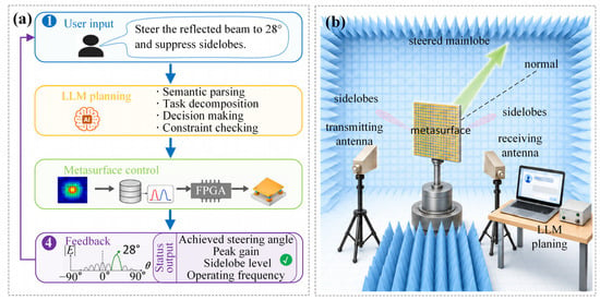
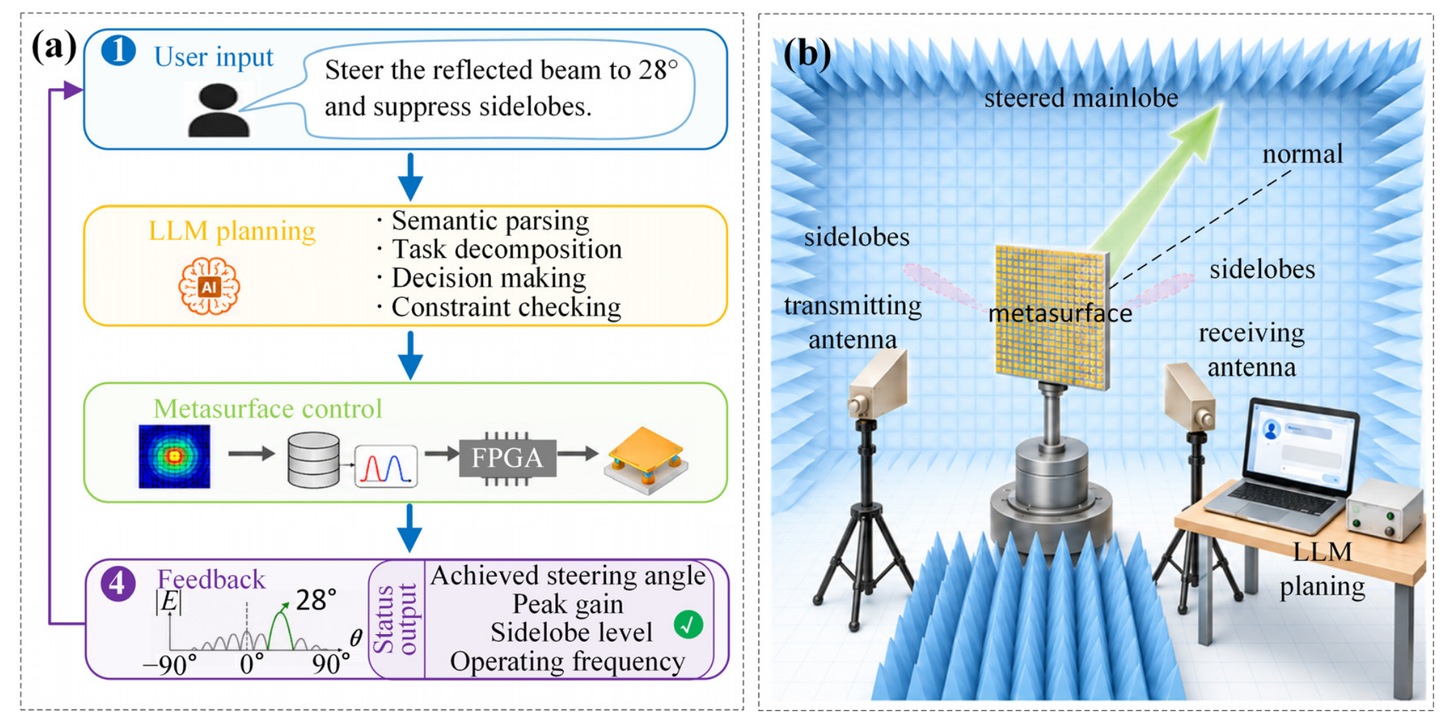
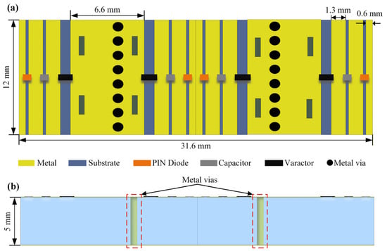
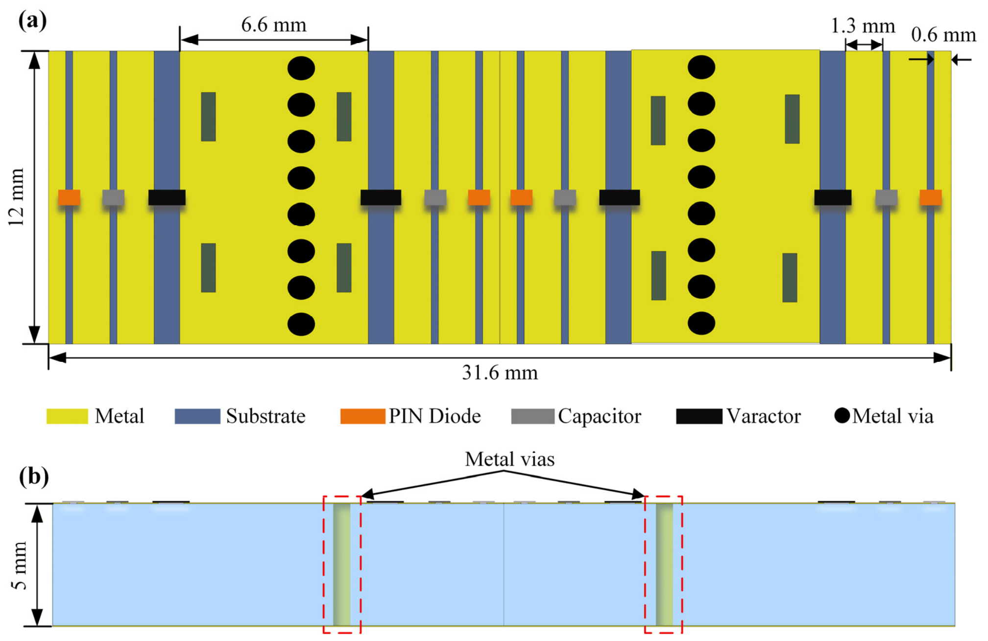
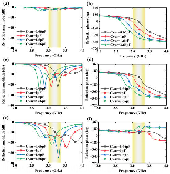
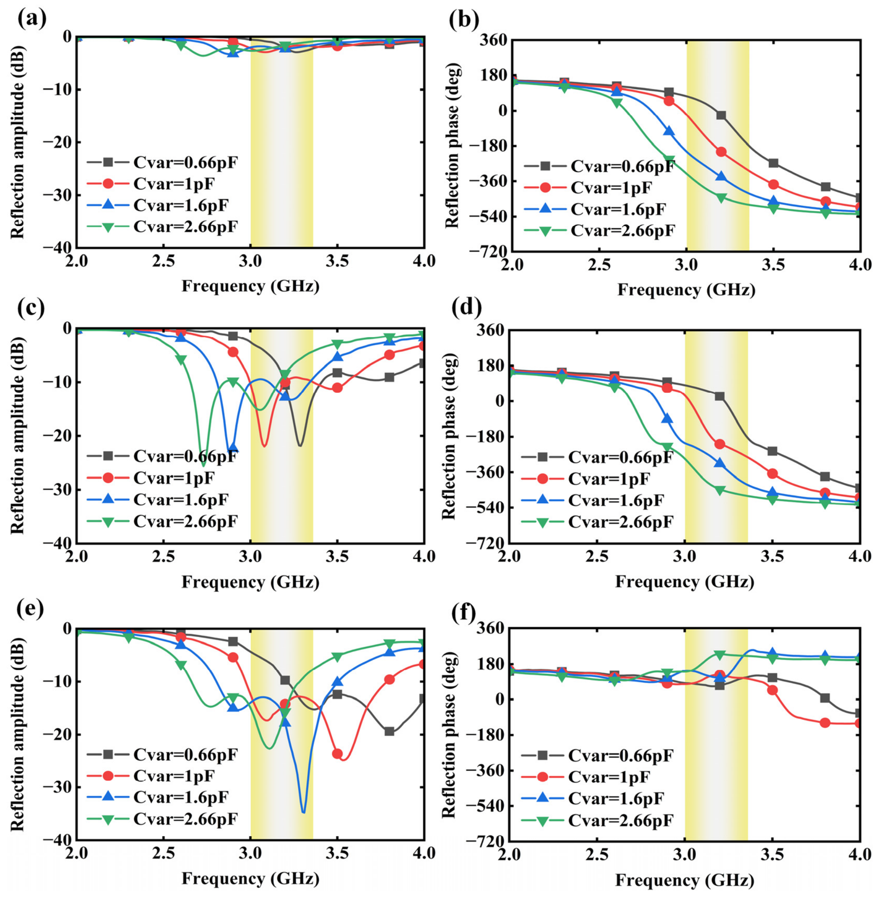
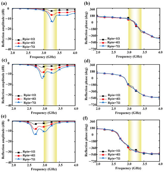
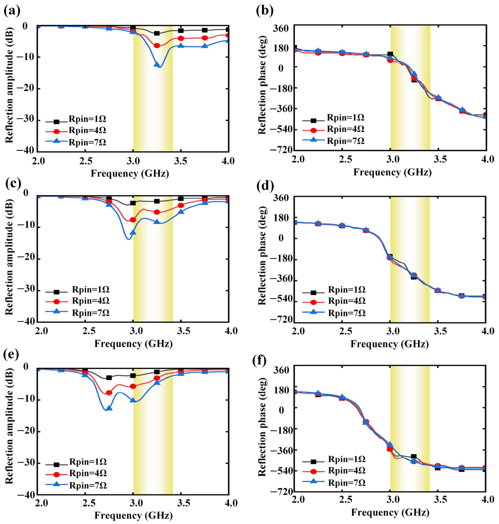
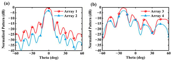
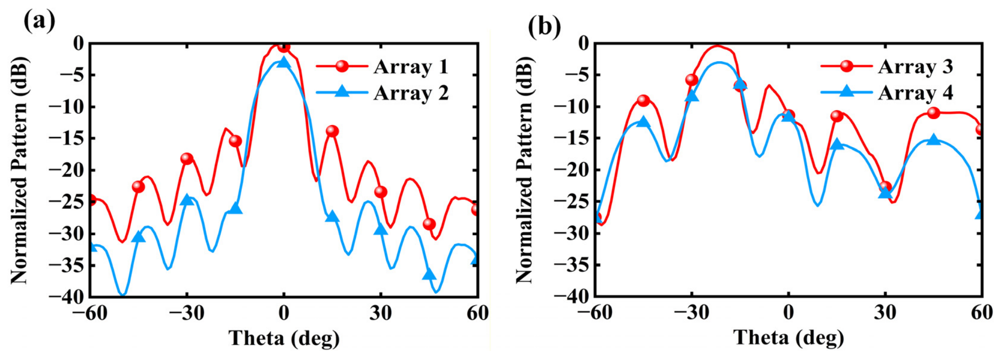
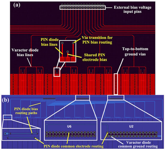
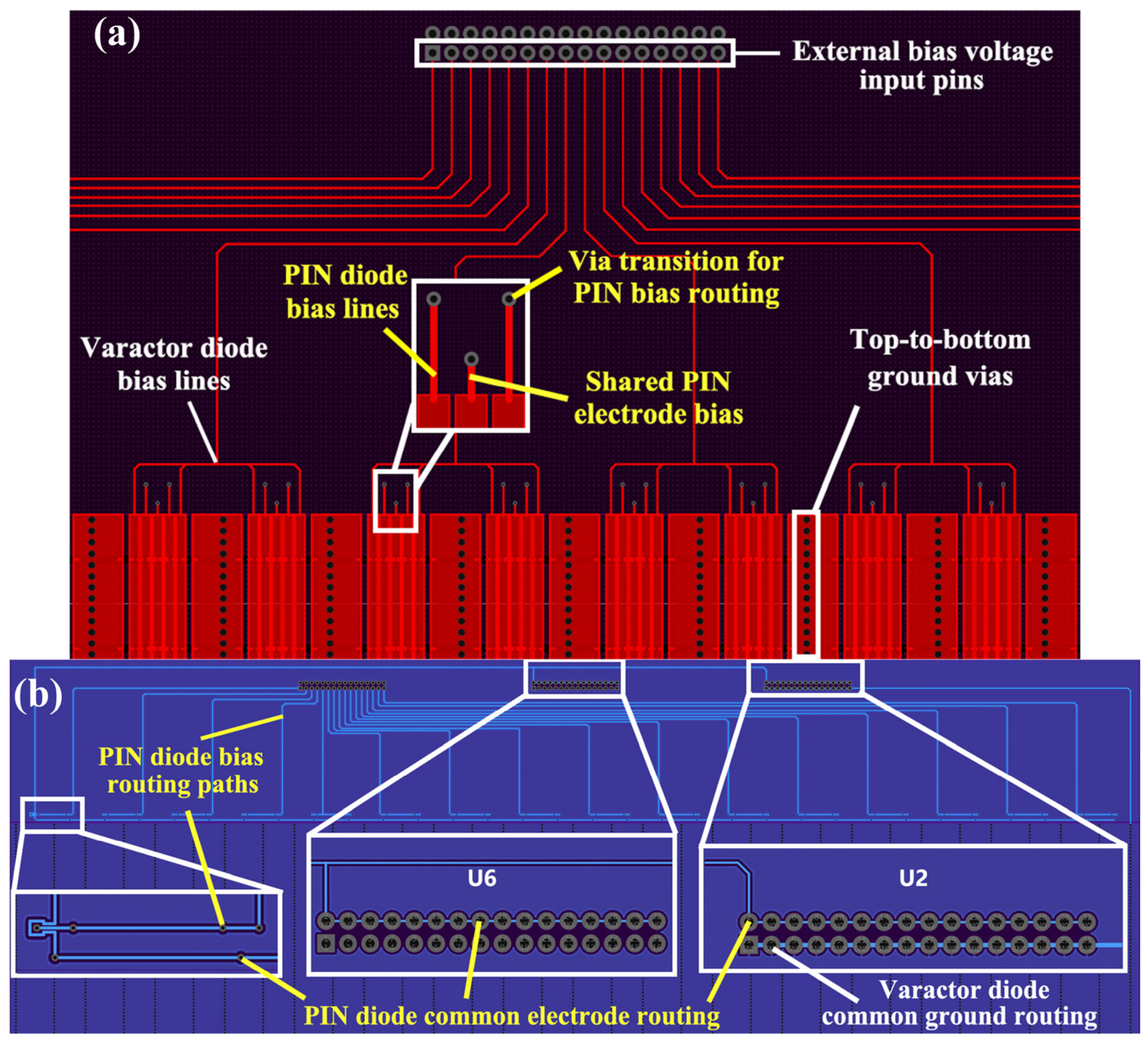
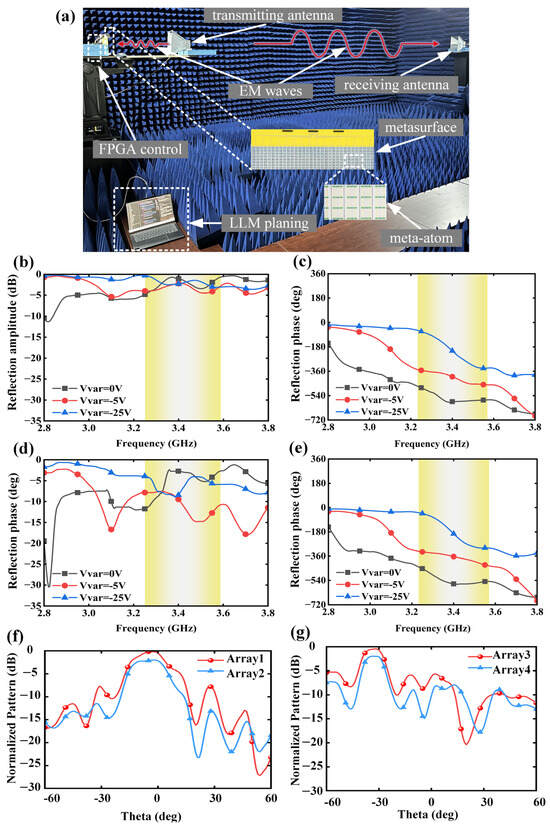
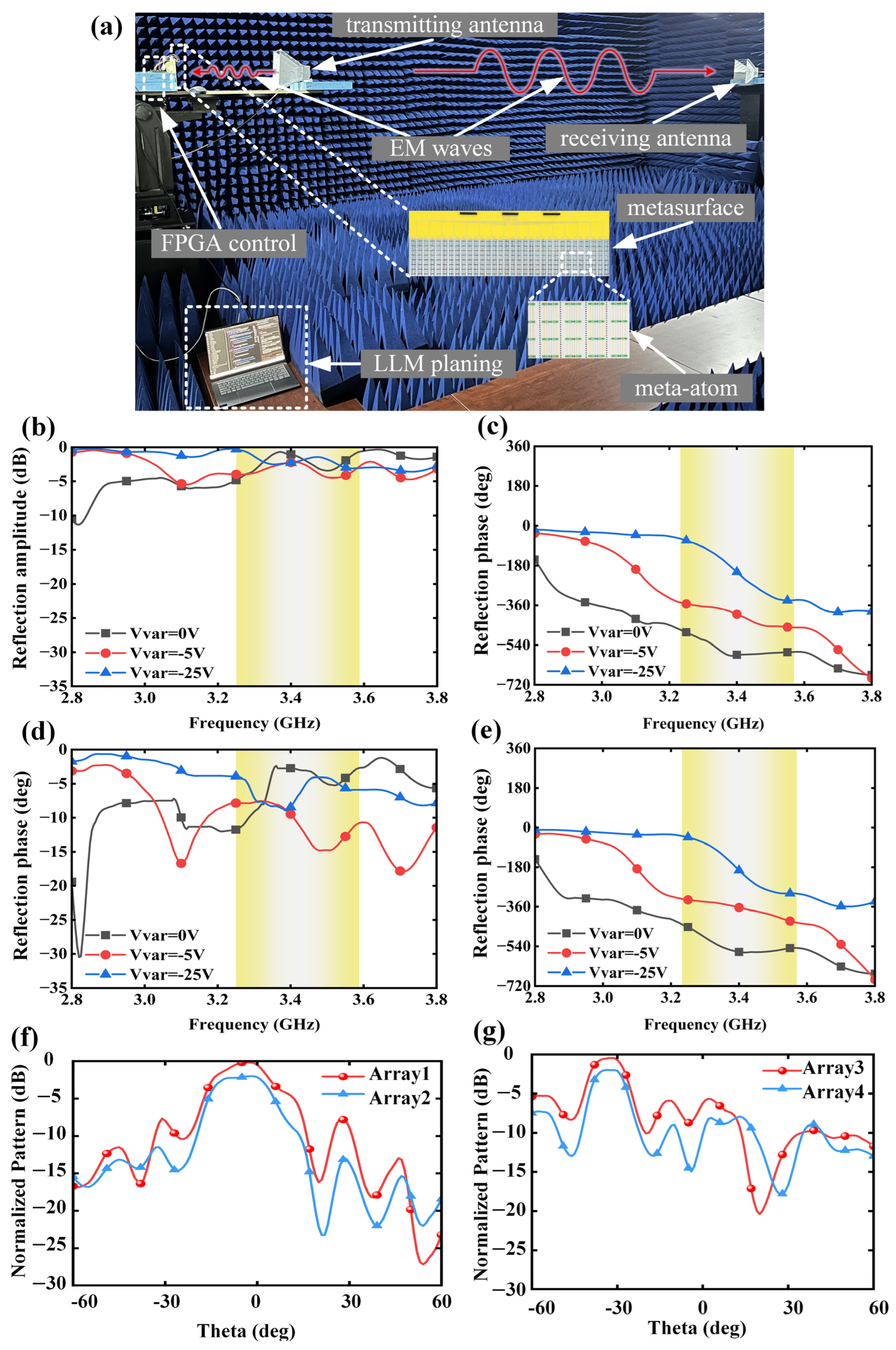

Disclaimer/Publisher’s Note: The statements, opinions and data contained in all publications are solely those of the individual author(s) and contributor(s) and not of MDPI and/or the editor(s). MDPI and/or the editor(s) disclaim responsibility for any injury to people or property resulting from any ideas, methods, instructions or products referred to in the content. |
© 2026 by the authors. Licensee MDPI, Basel, Switzerland. This article is an open access article distributed under the terms and conditions of the Creative Commons Attribution (CC BY) license.