


Abstract
Quantum computers endanger the security of digital signatures as they are generated today, e.g., by cryptographic algorithms like RSA, DSA, and ECDSA, whose security is based on algebraic problems. They have to be replaced by quantum-computer-resistant algorithms, so-called PQ (post-quantum) cryptography. This paper describes the performance results of one type of PQ digital signature embedded in the OPC UA communication protocol, measured in a typical industrial environment, demonstrating the communication between a sensor or actuator and an operator over a 5G campus network. The PQ digital signatures tested follow the stateful hash-based digital signature algorithm (SFH-DSA) as defined by ISO/IEC 14888-4. The tests show that this example of quantum-computer-resistant cryptographic algorithms is useful for practical use cases in industrial applications, which are characterized by real-time requirements and reliable communication between electronic components. Computation times, transmission times including overhead, lengths of digital signatures, memory requirements, and other characteristics are measured for different security levels and different types of hardware. These PQ-resistant digital signatures show very good performance properties, which make them useful for future industrial applications.
1. Introduction
Due to the computational power of quantum computers, today’s cryptographic algorithms used for digital signatures will no longer be secure. P. Shor published a paper [1] in 1994 which describes methods to solve the problems of factorization and discrete logarithms in polynomial time with quantum computers. At that time, it was more of a theoretical method, but it could become a technical one as the technology of quantum computers advances. Therefore, they have to be replaced by so-called PQ (post-quantum) crypto algorithms. Security agencies [2,3] and security experts recommend that cryptographic mechanisms based on the factorization and the discrete logarithm problem be replaced by PQ (post-quantum, i.e., quantum-computer-resistant) cryptographic algorithms. The intended time frame for this replacement is by 2030. Industrial companies, institutions, and all entities using digital signatures are under pressure to replace the implemented algorithms with new, quantum-computer-resistant digital signatures. Digital signatures are needed for the proof of origin of data and data integrity, which are absolutely necessary in industrial control processes which integrate sensors, actuators, operators, and communicate over (insecure) networks. The real-time behavior of these schemes is very essential for their use in industrial systems, which includes not only the computational time but also the transmission overhead caused by the digital signatures. This paper describes the results of a PQ algorithm tested end-to-end in a complete industrial application.
The analyzed PQ digital signature scheme uses one-time signatures and stateful digital signature mechanisms as standardized in ISO/IEC 14888-4 [4], also named SFH-DSA, which is based on [5] and the basics of hash-based digital signatures as described in Section 2. It uses one-time signatures and stateful hash trees, which means that each leaf of the hash tree can be used only once; therefore, the state of the tree (whose leaves are used/unused) has to be remembered and synchronized between the originator and the verifier.
There also exist other approaches for PQ digital signatures:
Lattice-based digital signatures: This method uses large multi-dimensional lattices (vector spaces). A set of n-dimensional base vectors spans the lattice, which consists of all linear combinations of these base vectors (mod q, so it is a finite vector space). If a signature is generated by multiplication with a secret vector, a noise vector is added to the result. This method is called Learning with Errors (LWE). It is very hard to find the secret vector to produce a valid signature. This method is standardized in FIPS 204 [6] and named ML-DSA.
Stateless hash-based digital signatures: This alternative, similarly to the stateful version described in Section 2, uses one-time signatures and multi-layer hash trees, but these trees have so many leaves (e.g., 260 or more) and additional random inputs that the probability of any leaf being used more than once is negligible. The advantage is that it is not necessary to stay synchronized with the state of the tree, but the disadvantage is more hash calculations and longer signatures. This variant is standardized in FIPS 205 [7] and called SLH-DSA.
ISO/IEC 14888-4 [4] has been chosen for implementation and testing the performance. This method is most promising because of the high computational speed of the hash calculations and low complexity. The only components needed for implementation are a secure random number generator and a secure, one-way, collision-resistant hash function.
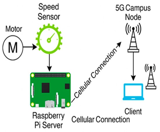
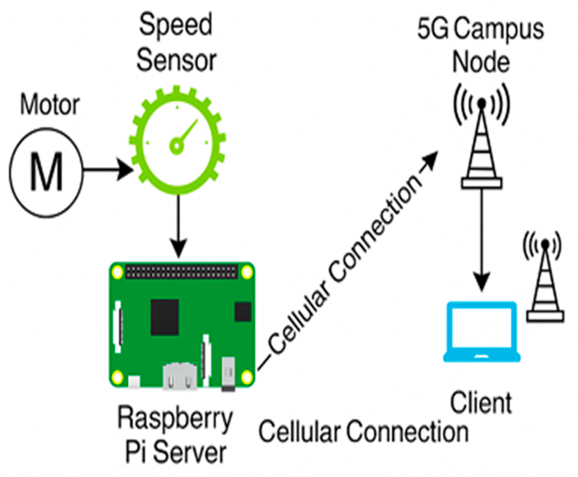
The test scenario consists of a speed sensor as the server and an operator console as the client. The transmission system between a sensor and operator is a 5G campus network, which is used or will be used more and more in industrial environments, e.g., large manufacturing halls, harbors, and industrial areas with moving sensors, actuators, or even operators. Both entities are connected wirelessly via 5G, or the sensor wirelessly via 5G and the operator via Ethernet to the node. OPC UA is used as the application protocol for the exchange of sensor data and management data. The digital signatures are embedded in OPC UA to support proof of origin on the application layer. Different hardware modules have been used to obtain a good overview of the impact of computational power on overall performance.
2. Basics of Stateful Hash-Based Digital Signatures (SFH-DSA)
2.1. One-Time Signatures
The principle of hash-based digital signatures with “infinite trees” was published by R. Merkle in 1986 [8] and 1989 [9] and has been studied in [10].
A one-time signature (OTS) is a type of digital signature scheme in which a single key pair is allowed to sign just one message. Signing with the same key pair a second time invalidates the security guarantee. This unique one-time requirement is the basic primitive that the stateful hash-based signature schemes depend on. Hash trees allow many signatures by constructing an authentication path up to the root of the tree, which means the public key.
The basic idea is as follows: To sign one bit, two random numbers s1 and s2 are generated, which will be used as signatures for Bit = 0 and Bit = 1, respectively. Then, y1 = H(s1) and y2 = H(s2) are calculated, where H is a secure one-way collision-resistant hash function, e.g., SHA-256. y1 and y2 are published with the authenticity of the signer; s1 and s2 stay secret. If the signer wants to send a bit, then either s1 or s2 is transmitted as the signature, depending on whether Bit = 0 or Bit = 1. The receiver calculates the hash value of the received signature and compares the result with the pre-published hash values. Merkle [9] attributed this method to Lamport [11].
Of course, this scheme is not practical because, for each bit, two random numbers have to be generated and two hash values published. Different improvements have been proposed [8,9], but the most attractive are called Winternitz signatures.
Remark: There is no reference to Winternitz’ idea. Merkle refers in [9] only to a personal conversation with Robert Winternitz in 1980.
2.2. Winternitz Signatures
Consider that strings of length m bits should be signed. Then, w = 2m is the so-called Winternitz parameter. A random number x is generated, and y = Hw−1(x) is calculated, which means that H(x) is iterated w − 1 = 2m − 1 times:
where w − 1 is the maximum number represented by m-bit. x is the private key, and y is the public key.
y = Hw−1(x) = H(H(…(H(x))…)) w − 1 iterations
If a signer wants to sign the message i1 …im, then H(x) is iterated i1 …im times (treating these m bits as a numeric value), giving the signature σ.
The receiver gets the message i1 … im and the signature σ. The signature is hashed (w − 1 − (i1 …im)) more times again, and the result is compared with the public key. If they match, the signature is valid. By this method, it is possible to sign a short number of bits, e.g., m = 4, 6, or 8. For larger values, too many hash iterations would be required.
To prevent forgery attacks, where an adversary replaces a message with one of higher numerical value, a checksum mechanism is introduced (in [8], this prevention was done by an additional reverse chain of iterations). This leads to the Winternitz One-Time Signature Plus (WOTS+) scheme used in ISO/IEC 14888-4 [4].
2.3. Winternitz One-Time Signature Plus (WOTS+)
WOTS+ extends the basic Winternitz scheme with a chaining mechanism. A private key is generated for each independent string from a pseudorandom seed. The public key is generated by repeatedly hashing each private key component (w − 1) times.
The resulting values, each obtained by applying the full (w − 1) hash iterations to the corresponding private key element, are pairwise-hashed bottom-up. This is called L-tree compression. The result is the WOTS+ public key. This allows a complete string to be signed with one random number and one public key.
For signing a message, the hash value of the message is segmented into ℓ1 digits of m-bit and expressed in base-w form. Each digit indicates the number of iterations applied to the corresponding private key element to produce the signature component. A checksum is computed over the base-w digits of the message to prevent substitution forgeries. This checksum of length ℓ2 digits extends the total number of elements in the signature.
2.4. Merkle Tree
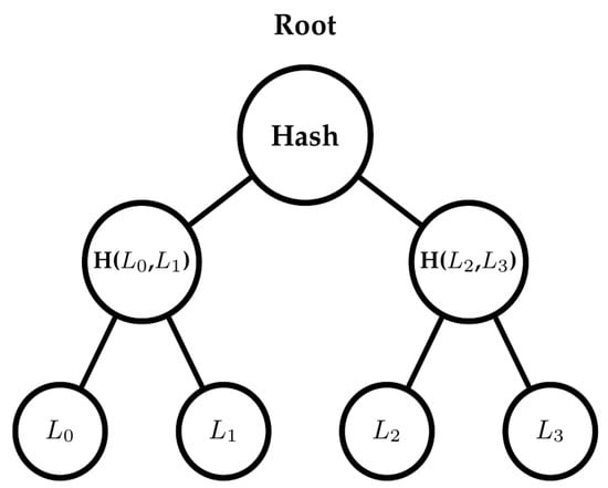
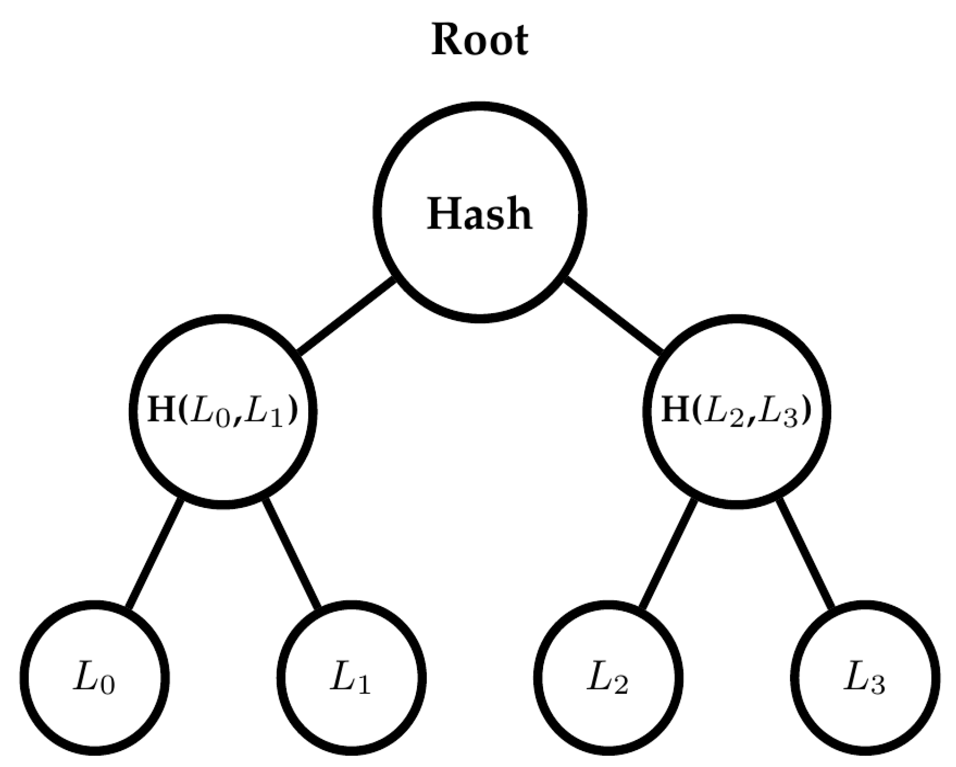
The Merkle tree combines several WOTS+ public keys into a single public key known as the root [9,10]. The leaves of the tree represent the WOTS+ public keys that have been compressed down, using the L-tree structure, which results in a single n-byte node, where n denotes the hash output length in bytes (n = 32 for SHA-256). The internal nodes are obtained by hashing two adjacent child nodes until only one root is achieved. The signer will provide the authentication path, which consists of the chain of hash values from the used leaf all the way up to the root (see Figure 1).
Figure 1.
Merkle tree with four leaves (L0–L3).
In a tree of height h, 2h signatures can be created. The signing time is proportional to h as a longer authentication path must be computed and transmitted.
2.5. Multi-Tree (XMSS-MT)
The eXtended Merkle Signature Scheme Multi-Tree (XMSS-MT) [12] extends XMSS by replacing a single large Merkle tree with a hierarchy of d layers, each containing smaller subtrees. The total signing capacity remains 2h, identical to single-tree XMSS with the same parameter h. The practical advantage is not a larger signature count but a reduction in per-signing cost: an authentication path within any single subtree is only h/d nodes long instead of h, and each subtree can be reconstructed independently without loading the entire structure into memory.
Layer numbering: Following [4], layers are numbered from 0 upward. Layer 0 is the bottom-most layer and the only layer that signs the message directly using WOTS+. Layers 1 through d−1 do not sign messages; each higher layer authenticates the roots of the subtrees in the layer immediately below it. The root of the topmost layer (layer d−1) serves as the global public key.
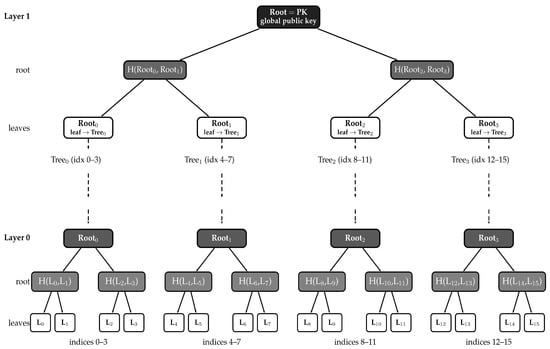
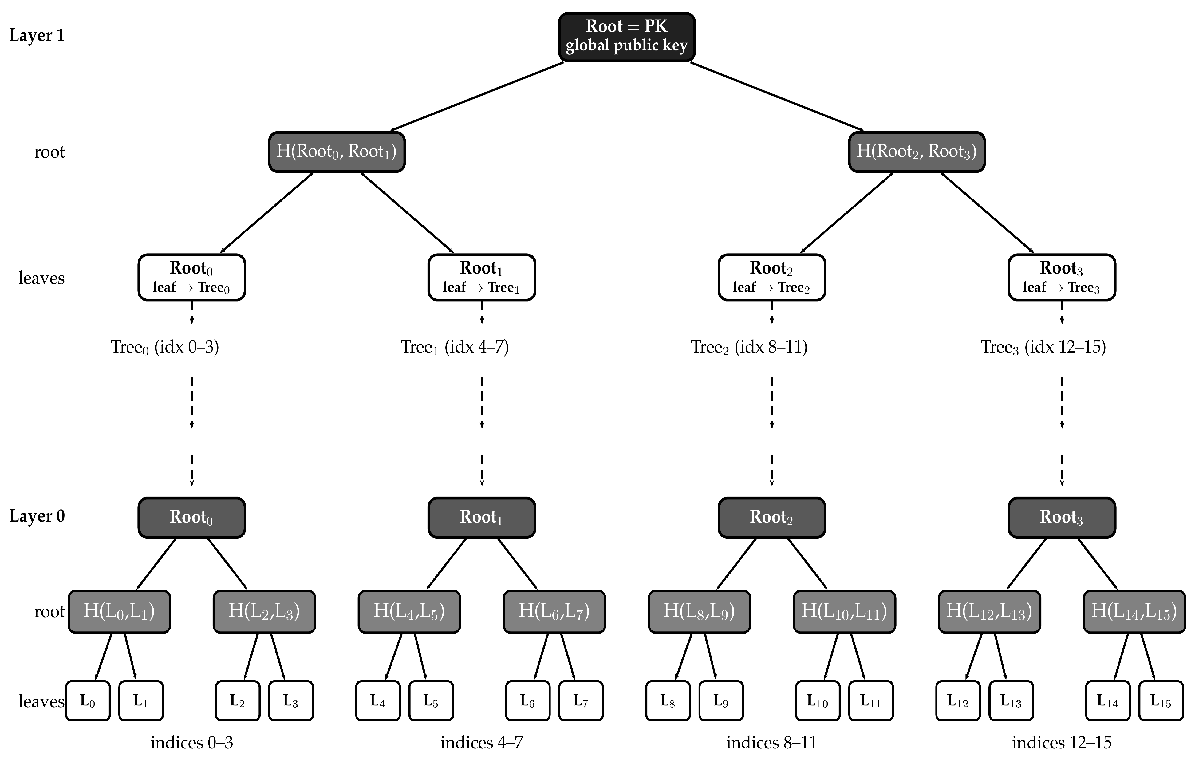
Figure 2 illustrates the XMSS-MT structure for h = 4, d = 2. Each subtree has height h/d = 2, giving 22 = 4 leaves per subtree. Layer 0 contains 2h/d = 4 subtrees—Tree0, Tree1, Tree2, and Tree3. Each subtree has four leaves, where every leaf is a WOTS+ public key compressed through the L-tree function. Layer 1 contains exactly one tree, referred to as the top tree. At key generation, each Layer 0 root is signed by a dedicated WOTS+ key pair in Layer 1. The compressed public key of that key pair becomes a leaf of the Layer 1 tree. The root of this single Layer 1 tree is the public key. The total signing capacity is four subtrees of four leaves per subtree, resulting in 24 = 16 signatures.
Figure 2.
XMSS-MT structure with h = 4, d = 2 (Layer 1 at the top and Layer 0 at the bottom).
Index decomposition: A single global index i runs from 0 to 2h − 1 = 15. For h = 4 and d = 2, the 4-bit index is split into two 2-bit groups using the (h/d) least significant bits to identify the leaf within the subtree and the remaining bits to identify the subtree:
idx_leaf = i mod 2(h/d) = i mod 4 (leaf position within the subtree)
idx_tree = i/2(h/d) = i/4 (number of subtree in Layer 0).
Indices 0–3 therefore map to Tree0 (leaves 0–3), indices 4–7 to Tree1, indices 8–11 to Tree2, and indices 12–15 to Tree3. The value idx_tree also identifies which leaf of the Layer 1 top tree holds the corresponding Layer 0 root. A single global index unambiguously encodes the complete signing path across all layers without any additional identifier.
3. Steps of Stateful Hash-Based Digital Signatures
3.1. Private Key
The private key is held only by the signer and never leaves the device. It contains three secret 32-byte seeds and a counter. The seeds are:
sk_seed (from which all WOTS+ private key elements are derived on demand)
sk_prf (used to generate a fresh randomizer for each signature)
pub_seed (also part of the public key).
The counter index records which leaf, and therefore which one-time key, will be used for the next signature. The signature index is identical to the leaf index. It simultaneously identifies the counter of signatures used so far and the position of the next leaf to be used in the bottom layer. The private key state (PK State) is specified by:
- sk_seed = [32 secret bytes, e.g., a7f 3c1e2…];
- sk_prf = [32 secret bytes, e.g., 2b9e04d8…];
- pub_seed = [32 bytes, same as in the public key];
- index (at the start, index = 0; after the first signature, index = 1, 2 after the second, and so on).
The individual WOTS+ private key elements are never all stored at once. They are computed on demand and can be reconstructed from sk_seed and the current leaf address, so the private key stays small regardless of tree size.
3.2. Public Key
The public key is the key held by the verifier. The public key is short, has a fixed size and acts as an encoding for the whole tree. For XMSS-MT, the public key contains only two values, both 32 bytes long, which are the root of the highest-level Merkle tree (pk_root) and a public seed (pub_seed), totaling 64 bytes. Regardless of the signature index used, the public key remains constant throughout the lifetime of the key pair. An example of how it looks is shown below:
- pk_root = 0dd0fe607f29ae54d1bfda1abaf6098a3968f269467916ea6d243ca3079c1848
- pub_seed = a3f1c2d509e8b74f1a2c3d4e5f6a7b8c9d0e1f2a3b4c5d6e7f8a9b0c1d2e3f41
3.3. Certificate
The certificate follows the X.509v3 structure and is DER-encoded. Since OpenSSL 1.1 does not natively support XMSS-MT key types, the SubjectPublicKeyInfo field contains a placeholder key to satisfy the mandatory X.509 structure. The actual XMSS-MT public key material and scheme parameters are embedded as custom ASN.1 extensions using a private OID arc reserved for this prototype (1.3.6.1.4.1.99999.1). The following fields carry the XMSS-MT information:
- pk_root (32 bytes)—root of the topmost Merkle tree (public key);
- pub_seed (32 bytes)—public seed for hash computations;
- n—hash output length in bytes;
- h—total tree height;
- d—number of layers;
- w—Winternitz parameter.
The certificate is generated once during key generation and distributed to all verifying parties. Because X.509v3 certificates do not natively support XMSS-MT, the certificate is self-signed using a placeholder RSA-2048 key solely to satisfy the mandatory X.509 signature field. The actual authenticity of the public key material is established through the custom ASN.1 extensions, not through the RSA signature.
3.4. Construction of the Tree
The tree is created only once, while generating keys upon system initialization. From sk_seed, a WOTS+ key pair is obtained for each leaf node position. Every WOTS+ public key is compressed to 32 bytes via the L-tree and becomes a leaf node of the Merkle tree. Leaves are then hashed pairwise (siblings of the next highest node) layer by layer, until the final single root is obtained. In the case of XMSS-MT, this procedure is applied to each layer; roots of the bottom layers are each signed by a dedicated WOTS+ key pair in the layer above; the compressed public key of that key pair becomes a leaf node of the higher layer tree. This final root constitutes the public key.
The tree is capable of generating up to 2h signatures. Once the tree is constructed, the signer only needs to select the next unused leaf node using the current index. The index is persisted to a file (xmss_index.bin) and atomically incremented after each signature to prevent reuse. The WOTS+ private key elements and authentication path sibling hashes for that leaf are recomputed on demand from sk_seed using a deterministic pseudorandom function (PRF) keyed by sk_seed and an internal address structure (ADRS) as defined in ISO/IEC 14888-4 [4], which encodes the layer, tree and node position. Since all derivations are deterministic, any node in the tree can be reproduced at any time from sk_seed alone. The public key root pk_root is computed once during key generation and stored in the certificate—it does not need to be recomputed during signing.
Memory-Signer: The WOTS+ private key elements are never stored permanently. They are recomputed on demand from sk_seed using the current leaf index. Therefore, the persistent storage on the signer side contains only the three 32-byte seeds (sk_seed, sk_prf, pub_seed) and the 4-byte index counter, amounting to approximately 100 bytes. Additional temporary memory is required during signing for tree traversal and authentication path computation, but nothing beyond the 100 bytes needs to be persisted between sessions.
Memory-Verifier: The verifier only needs the certificate, which contains pk_root (32 bytes), pub_seed (32 bytes), and the scheme parameters n, h, d, and w. The total persistent storage on the verifier side is the certificate file of a few hundred bytes. No private material and no tree structure are required on the verifier side. Index tracking for replay attack prevention should be implemented according to the system requirements.
3.5. Signature
Input: The message M that needs to be signed.
A signature consists of the following components:
- Index (4 bytes): This component indicates which leaf node was selected, and hence it provides information on which path needs to be reconstructed during verification.
- Randomizer r (32 bytes): This is a new pseudorandom value generated using sk_prf and index to make sure each signature is unique.
- WOTS+ signature for each layer: Each layer contains ℓ = ℓ1 + ℓ2 elements of n bytes each, where ℓ1 is the number of base-w message digits and ℓ2 is the number of checksum digits. For n = 32 and w = 16, ℓ1 = 64 and ℓ2 = 3, giving ℓ = 67 elements × 32 bytes = 2144 bytes per layer. This value is fixed for a given n and w. It does not depend on the tree height h. Each signature element is produced by hashing the corresponding private key element forward by the number of steps given by the base-w digit of the message digest, including the checksum digits.
- Authentication path for each layer: This component contains h/d sibling hashes of 32 bytes each, from the used leaf up to the layer root. The sibling hashes are not stored permanently; they are reconstructed on demand during signing from sk_seed using a deterministic PRF keyed by an internal address structure (ADRS) as defined in ISO/IEC 14888-4 [4]. This keeps persistent memory minimal at the cost of additional computation, which is why signing time scales with h.
Output: A fixed-length binary byte string where its length depends only on the parameter set and not on the message length.
The complete signature size for the parameters (n, h, and d) is computed according to [4]:
where:
SigLen = 4 + n + d∙((l + h/d)∙n)
The 4 bytes is for the index
n bytes is for the randomizer
ℓ ∙ n bytes is the WOTS+ signature per layer (fixed for a given n and w; includes both ℓ1 message digits and ℓ2 checksum digits)
(h/d) ∙ n bytes is the authentication path per layer (depends on h)
d is the number of layers.
3.6. Transmission
Two items are transferred from the signer to the verifier: the message M and the complete signature. The message is a sensor measurement with timestamp, typically 30 to 40 bytes. The complete signature consists of the index (4 bytes), the randomizer r (n bytes), and for each layer d, the WOTS+ signature (ℓ ∙ n bytes) and the authentication path (h/d ∙ n bytes).
The WOTS+ signature alone is not sufficient for verification—the authentication path must also be transmitted so the verifier can reconstruct the root and compare it with pk_root from the certificate.
For Set 1 (h = 10, d = 2), the total signature size is 4644 bytes. The certificate is exchanged only once at setup and does not travel with each message.
3.7. Verification
Inputs: The received message, the received signature, and the certificate (containing pk_root, pub_seed, and the values n, h, d, and w).
The verifier derives the index and the randomizer from the signature and computes the message digest. Then, it works up layer by layer: the remaining WOTS+ chain steps are completed to recover the WOTS+ public key, which is then compressed to a leaf via the L-tree and hashed upward along the authentication path to obtain the root of that layer. The roots generated in each lower layer act as inputs to the next highest layer. In the end, a root value is generated after processing all d layers.
Outputs: If the calculated root is equal to pk_root in the certificate, then the signature is correct. Any discrepancy between the two, such as any modification in the message, signature, or key used, would result in failure during verification.
4. Results
Computational Times and Memory for Different Security Levels
All measurements were performed on a Raspberry Pi 3 (ARM Cortex-A53, 1.2 GHz quad-core). The XMSS-MT scheme was implemented in C, following the pseudocode defined in ISO/IEC 14888-4 [4]. The three parameter sets tested are defined in Table 1. For all sets, n = 32 bytes and w = 16 are fixed according to [4]; only the total tree height h and the number of layers d vary.
Table 1.
XMSS-MT parameter sets with signature size and memory footprint.
Only the bottom layer leaves are used for signing messages and carry the global signature index. Upper-layer leaves sign the roots of the subtrees below them, not messages directly. Internal nodes are uniquely addressed by their layer, height, and position within the tree, but do not carry a signature index.
The signature size and maximal number of signatures grow with h and d because each additional layer adds one WOTS+ signature block and one authentication path. The size is given by the formula below from [4]:
where ℓ = 67 for w = 16.
SigLen = 4 + n + d∙((l + h/d)∙n)
For Set 1 (n = 32, w = 16, h = 10, d = 2, h/d = 5):
SigLen = 4 + 32 + 2 ∙ ((67 + 5) ∙ 32) = 4644 bytes (Table 1)
Set 2 and Set 3 follow the same calculation with d = 4 and d = 6, respectively, giving 9252 and 13,860 bytes. The signature structure consists of a 4-byte index, an n = 32 bytes randomizer and for each of the d layers, ℓ × n = 2144 bytes for the WOTS+ signature and (h/d) ∙ n = 160 bytes for the authentication path, as detailed in Section 3.5. The public key is always 64 bytes (pk _root || pub_seed) regardless of the security level. The private key state held in persistent storage is only about 100 bytes for all parameter sets—three 32-byte seeds plus a 4-byte index counter—because WOTS+ key elements are derived on demand from the seed rather than stored in full.
Table 2 consolidates all measured computational times alongside the signature size for direct comparison. Key generation is a one-time cost at device provisioning. Signing runs on the Raspberry Pi 3 (signer side). Verification runs on a laptop client connected to the same local network.
Table 2.
XMSS-MT computational times and signature sizes on Raspberry Pi 3.
Key generation: Key generation time is nearly flat across all three sets (259–281 ms). It includes the construction of all Layer 0 subtrees and the Layer 1 tree as required by ISO/IEC 14888-4 [4]; all subtrees are built temporarily to derive the global public key root, after which only the root and the secret seed are retained. The timing reflects the fixed subtree height h/d = 5 for all sets; only the number of layers increases, and layers are built sequentially. Since key generation occurs only once at device provisioning, this cost has no effect on runtime signing performance.
Signing time: Signing time scales approximately linearly with h. Each additional tree level requires computing more hash operations along the authentication path, so Set 3 takes roughly three times as long as Set 1. The variance between minimum and maximum observed signing times is small (less than 50 ms for all sets), which confirms stable, deterministic behavior on the Raspberry Pi 3.
Verification time: Verification is extremely fast across all sets, never exceeding 3.65 ms. The verifier only needs to complete the remaining WOTS+ hash chain steps and recompute the authentication path—a logarithmic number of hash operations. This makes the client side computationally negligible regardless of the chosen security level. The verification time does not include time for checking the freshness of the counter.
Memory: Memory usage is constant and minimal across all parameter sets. The public key is always 64 bytes, and the private key persistent state is approximately 100 bytes. The only quantity that grows with the security level is the signature size, increasing from 4.6 kB (Set 1) to 13.9 kB (Set 3). For periodic sensor data transmission, this overhead is acceptable; applications with very tight bandwidth budgets should prefer Set 1.
Interesting comparable performance results for an ARM Cortex-M4 (bare-metal) can be found in [13].
5. Integration of PQ Digital Signature in OPC UA
5.1. Security Hierarchy
Security is integrated into the application layer in the OPC UA over TCP/IP communication stack without changing the communication protocol stack. The 5G campus network enables wireless real-time transmission, OPC UA offers the information model and address space [14], and WOTS+ with XMSS-MT provides a hash-based, forward-secure authentication mechanism, guaranteeing quantum-resistance regardless of the transport security mode.
There are three OPC UA variable (data model) nodes related to speed. Sensor object with signed data stored:
- current.sensor.rawdata.string (plain text with timestamp);
- current.sensor.signature (XMSS-MT signature in ByteString format);
- current.signature.index (index used for signature creation in UInt32).
Nodes storing signature and index are set to read-only state to avoid tampering.
5.2. Processing Steps at the Signer Side
Source coding: The Raspberry Pi reads the motor speed sensor via I2C (through a Raspberry Pi Pico and RS-485 interface) and formats each reading as a UTF-8 string containing the speed value in RPM and a high-precision timestamp.
Signature: The string is hashed using SHA-256. The message digest is signed using the xmssmt_sign() method, with the current index read from the xmss_index.bin file to produce a one-time XMSS-MT signature. The index is then atomically incremented and persisted to xmss_index.bin using a write-then-rename approach to ensure crash safety. A POSIX mutex prevents concurrent access from I2C reader and signing threads.
Embedding in OPC UA: Values for all three variable nodes are set atomically using the UA_Server_writeValue() method. Subscribed clients receive a change notification and retrieve the raw data, signature, and index in a single UA_ReadRequest call to ensure consistency.
5.3. Processing Steps at the Verifier Side
Receive notification: The OPC UA client receives a change notification from the server subscription and issues a UA_ReadRequest to retrieve the raw data string, signature and index in a single call.
Index check: The received index is compared with the last accepted index stored locally on the verifier. If the received index is not strictly greater than the last accepted index, the message is rejected as a potential replay attack. This verifier-side freshness check was not implemented in this work, because the state management of the system strongly depends on the individual system, and is left as future work.
Certificate retrieval: The verifier retrieves the certificate containing pk_root, pub_seed and the parameters n, h, d, and w.
Verification: The raw data string together with the signature and certificate parameters is passed to xmssmt_verify(). The function reconstructs the authentication root layer by layer—completing the remaining WOTS+ hash chain steps, compressing via the L-tree, and hashing upward along the authentication path—and compares the final computed root with pk_root from the certificate. The verification does not include the one-time use of the counter. This step was not implemented, because it will depend on the individual solution for state management, which has to be chosen according to the system situation (global, distributed, local, time protocols, etc.).
Output: If the computed root matches pk_root, the signature is valid and the sensor data is accepted. Otherwise, the message is rejected.
6. Test Environment
6.1. Hardware Setup
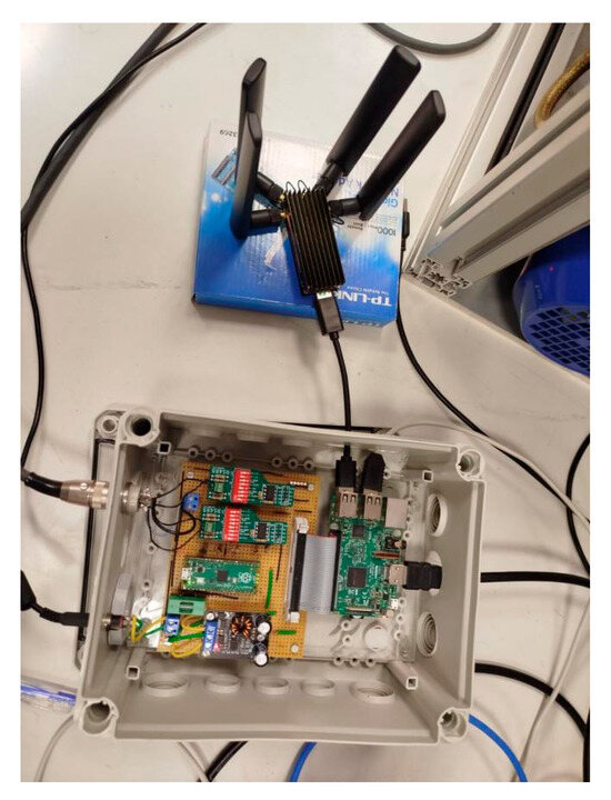
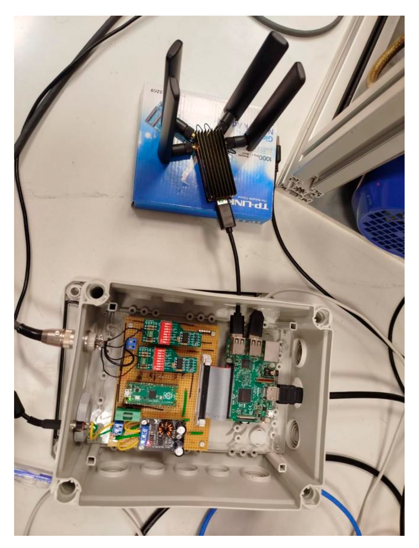
The test system is built around a Raspberry Pi 3 acting simultaneously as the OPC UA server and the XMSS-MT signer. The Raspberry Pi is housed in a custom enclosure together with a Raspberry Pi Pico microcontroller, two RS-485 interface modules for the motor and speed sensor, and a DC-DC power module. The speed sensor output is processed by the Pico, which forwards the readings to the Raspberry Pi 3 over the I2C bus. A laptop runs the OPC UA client and the XMSS-MT verification module. Table 3 lists all components and their roles.
Table 3.
Summary of hardware components used in the experimental setup.
Figure 3 shows the complete laboratory test setup with the Raspberry Pi 3, 5G module sensor interfaces, and Pico controller.
Figure 3.
Laboratory test setup.
6.2. Software and Measurement Methodology
The XMSS-MT implementation is written in C and follows [4]. The OPC UA server is built with the open62541 library. The client is implemented in C++ with extern “C” linkage to the C cryptographic functions. All measurements use C++ chrono timestamps recorded on both the server side (after signing) and the client side (on message receipt).
Every measurement cycle covers the following steps in sequence:
- The I2C sensor reading is acquired and formatted as a string with a timestamp (30–40 bytes).
- The Raspberry Pi 3 computes the SHA-256 digest and generates the XMSS-MT signature using the current index.
- The signed message and signature are published to the OPC UA variable nodes.
- The laptop client reads the nodes, extracts the message and signature, and runs XMSS-MT verification.
- Signing and reception timestamps are compared to derive the end-to-end delay.
Each parameter set was run multiple times, and the average, minimum, and maximum values were recorded. The total payload transmitted per cycle consists of the raw sensor string (≈38 bytes) and the XMSS-MT signature. For Set 1, this gives a total of approximately 4644 + 38 ≈ 4682 bytes (≈4.6 kB) per message.
The measurements were conducted under two network configurations for comparison:
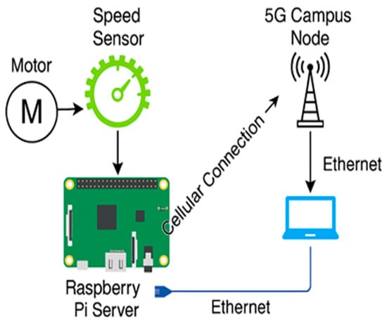
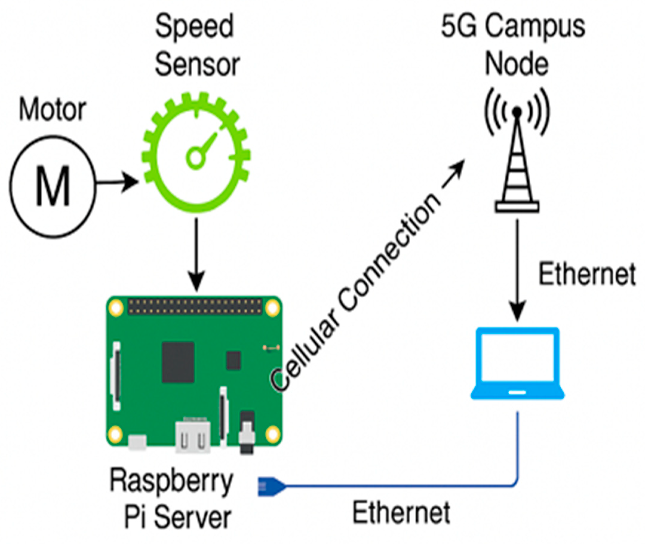
- Ethernet baseline—Raspberry Pi 3 connected directly to the laptop through a lab switch. Figure 4 shows this setup.
- OPC UA over the 5G campus network—Raspberry Pi 3 connected via the Fibocom FM160 modem to the Aircell NR-02 base station and Open5GS core. Figure 5 shows this setup.
Figure 4.
Ethernet-based XMSS-MT measurement setup.
Figure 5.
5G campus network-based XMSS-MT measurement setup.
6.3. Test Results and Evaluation
Transmission Times and End-to-End Delay Ethernet
Under the Ethernet baseline, transfer and end-to-end times are dominated by XMSS-MT signing on the Raspberry Pi 3. Table 4 presents the measured values.
Table 4.
Transfer time and total end-to-end delay under Ethernet.
Ethernet introduces negligible transport delay; timing is highly consistent with very little jitter across repeated runs. The end-to-end delay is the sum of signing, transfer and verification time. Signing is the dominant contributor, while verification remains below 3.65 ms across all sets.
Transmission Times and End-to-End Delay 5G Campus Network
Signing time is identical to the Ethernet case since it depends only on the Raspberry Pi 3 CPU. Table 5 shows the results under the 5G campus network.
Table 5.
Transfer time and total end-to-end delay under the 5G campus network.
The additional end-to-end delay under 5G compared to Ethernet is due to the higher transfer time over the wireless network—approximately 84 ms for Set 1 and 139 ms for Set 3—and increases with signature size as larger payloads experience more latency over 5G. Table 6 provides a side-by-side summary of all key metrics across both network types.
Table 6.
Complete performance summary for all parameter sets under Ethernet and 5G.
7. Conclusions and Outlook
The findings confirm that XMSS-MT is practically deployable in industrial OPC UA environments. However, there are three issues to consider.
State Management: Each leaf index must be used only once. Reusing an index breaks the security of WOTS+ permanently. Alternatives for handling the system state are discussed in [15].
In this work, the index is saved atomically to xmss_index.bin after each signature, with a mutex to prevent simultaneous access.
The signer publishes the last-used index via the OPC UA node current.signature.index after every signature. On the signer side, the index is reserved atomically before signing and persisted to xmss_index.bin using a write-then-rename approach, ensuring crash safety. Verifier-side freshness checking—tracking the last accepted index and rejecting equal or lower values—was not implemented in this work and is left to future works. For stronger protection against device reset or backup restore, a hardware counter such as a TPM chip is recommended on the signer side.
Signing Latency: The overhead time is determined by signing, which depends on h. Set 1 works well with a 1 s cycle; Sets 2 and 3 may require additional processing power or longer update intervals.
Signature Size: The payload sizes range from 4.6 kB (Set 1) to 13.9 kB (Set 3). For high frequencies or low-bandwidth applications, Set 1 may be the best choice.
From a future perspective, the main improvements to be expected include efficient state management for multiple nodes, hardware-accelerated SHA-256 and software optimization to minimize signing time, and dynamic parameter selection during runtime. With the upcoming 2030 standard migration date, this prototype represents the basis for further developments in the industrial sector.
Author Contributions
Conceptualization, C.R. and N.Ž.; methodology, C.R. and N.Ž.; software, A.V.; validation, C.R.; formal analysis, N.Ž.; investigation, C.R.; resources, C.R.; data curation, N.Ž.; writing—original draft preparation, A.V.; writing—review and editing, C.R. and N.Ž.; visualization, N.Ž.; supervision, C.R.; project administration, C.R. All authors have read and agreed to the published version of the manuscript.
Funding
This research received no external funding.
Institutional Review Board Statement
Not applicable.
Informed Consent Statement
Not applicable.
Data Availability Statement
The original contributions presented in this study are included in the article material. Further inquiries can be directed to the corresponding author. No data sets have been used. The test data are generated during the tests, and the results are published in the paper.
Conflicts of Interest
The authors declare no conflicts of interest.
References
- Shor, P.W. Polynomial-Time Algorithms for Prime Factorization and Discrete Logarithms on a Quantum Computer. SIAM J. Comput. 1997, 26, 1484–1509. [Google Scholar] [CrossRef] [Scilit]
- BSI and Partners. Securing Tomorrow, Today: Transitioning to Post-Quantum Cryptography. Joint Statement from Partners of 18 EU Member States. 27 November 2024. Available online: https://www.bsi.bund.de/SharedDocs/Downloads/EN/BSI/Crypto/PQC-joint-statement.pdf (accessed on 1 June 2026).
- National Institute of Standards and Technology. NIST IR 8547 (ipd): Transition to Post-Quantum Cryptography Standards; NIST: Gaithersburg, MD, USA, 2024. Available online: https://nvlpubs.nist.gov/nistpubs/ir/2024/NIST.IR.8547.ipd.pdf (accessed on 1 June 2026).
- ISO/IEC 14888-4:2024; IT Security Techniques—Digital Signatures with Appendix—Part 4: Mechanisms Using One-Way Hash Functions. International Organization for Standardization: Geneva, Switzerland, 2024.
- McGrew, D.; Curcio, M.; Fluhrer, S. Leighton-Micali Hash-Based Signatures; RFC 8554; Internet Engineering Task Force (IETF): Wilmington, DE, USA, 2019; Available online: https://datatracker.ietf.org/doc/html/rfc8554 (accessed on 1 June 2026).
- National Institute of Standards and Technology. FIPS PUB 204: Module-Lattice-Based Digital Signature Standard (ML-DSA); NIST: Gaithersburg, MD, USA, 2024. Available online: https://csrc.nist.gov/pubs/fips/204/final (accessed on 1 June 2026).
- National Institute of Standards and Technology. FIPS PUB 205: Stateless Hash-Based Digital Signature Standard (SLH-DSA); NIST: Gaithersburg, MD, USA, 2024. Available online: https://csrc.nist.gov/pubs/fips/205/final (accessed on 1 June 2026).
- Merkle, R. A Digital Signature Based on a Conventional Encryption Function. In Advances in Cryptology—CRYPTO ’87; Pomerance, C., Ed.; Lecture Notes in Computer Science; Springer: Berlin/Heidelberg, Germany, 1988; Volume 293, pp. 369–378. [Google Scholar]
- Merkle, R. A Certified Digital Signature. In Advances in Cryptology—CRYPTO ’89; Brassard, G., Ed.; Lecture Notes in Computer Science; Springer: Berlin/Heidelberg, Germany, 1990; Volume 435, pp. 218–238. [Google Scholar]
- Ruland, C. Realizing Digital Signatures with One-Way Hash Functions. Cryptologia 1993, 17, 285–300. [Google Scholar] [CrossRef] [Scilit]
- Lamport, L. Constructing Digital Signatures from a One-Way Function; SRI International Technical Report CSL-98; SRI International: Menlo Park, CA, USA, 1979. [Google Scholar]
- Hülsing, A.; Butin, D.; Gazdag, S.; Rijneveld, J.; Mohaisen, A. XMSS: eXtended Merkle Signature Scheme; RFC 8391; Internet Engineering Task Force (IETF): Wilmington, DE, USA, 2018; Available online: https://datatracker.ietf.org/doc/html/rfc8391 (accessed on 1 June 2026).
- Campos, F.; Kohlstadt, T.; Reith, S.; Stoettinger, M. LMS vs XMSS: Comparison of Stateful Hash-Based Signature Schemes on ARM Cortex-M4. Cryptology ePrint Archive, Paper 2020/470. Available online: https://eprint.iacr.org/2020/470 (accessed on 1 June 2026).
- IEC 62541-3:2020; OPC Unified Architecture—Part 3: Address Space Model. International Electrotechnical Commission: Geneva, Switzerland, 2020.
- McGrew, D.; Kampanakis, P.; Fluhrer, S.; Gazdag, S.; Butin, D.; Buchmann, J. State Management for Hash-Based Signatures. Cryptology ePrint Archive, Paper 2016/357. Available online: https://eprint.iacr.org/2016/357 (accessed on 1 June 2026).

Disclaimer/Publisher’s Note: The statements, opinions and data contained in all publications are solely those of the individual author(s) and contributor(s) and not of MDPI and/or the editor(s). MDPI and/or the editor(s) disclaim responsibility for any injury to people or property resulting from any ideas, methods, instructions or products referred to in the content. |
© 2026 by the authors. Licensee MDPI, Basel, Switzerland. This article is an open access article distributed under the terms and conditions of the Creative Commons Attribution (CC BY) license.