


Abstract
Türkiye has large offshore wind potential and a new tender in preparation, but no operating farm. This review asks how far Turkish research can support the design of a first project. A structured search of four databases, including the national thesis center, was run on 28 October 2026. The review includes 102 studies of Turkish sites, 24 of them graduate theses. The review covers the four Turkish seas and six candidate sites. Most studies stop at screening or techno-economic feasibility; none uses offshore measurements at a candidate site. Published peak wave periods are typically 4–5 s, but return values and wind–wave misalignment are missing for most sites. Coastal peak ground acceleration near the sites is 0.18–0.56 g, and no site has a site-specific hazard analysis. The 2026 candidate areas lie mostly in water shallower than 60 m, so a first project would most likely be fixed-bottom. Floating systems matter for the deeper resource, yet only one floating concept has been sized for a Turkish site. Port and grid studies rarely go beyond distance, and no cost study tests the draft tender terms. The methods are standard; the missing pieces are measured site data and worked designs at the candidate sites.
1. Introduction
Global offshore wind capacity reached 92.5 GW by the end of 2025, with approximately 50 GW under construction. Annual installations are expected to accelerate over the coming decade despite policy, grid, auction, and supply chain constraints [1,2]. Three properties drive that growth: wind speeds at sea are higher and steadier than onshore, ships can deliver turbines too large for roads, and siting conflicts are fewer. Early offshore wind projects used fixed-bottom foundations in shallow waters [3,4,5]. Development has since moved toward larger, more distant, and technically demanding projects. For instance, Dogger Bank C lies about 196 km from the UK shore at its nearest point [6].
In these cases, floating systems enable offshore wind deployment beyond the conventional fixed-bottom depth limits imposed by economic and technical constraints. Türkiye (Turkiye) is one of the countries where steep bathymetric gradients bring deep water close to shore [7]. The feasibility of floating wind turbines has been demonstrated through spar, semi-submersible, and tension leg platform (TLP) concepts [8,9,10], highlighting the applicability of the technology despite its lower maturity [11,12,13]. However, floating systems also introduce additional engineering challenges [14,15,16]. Strong interactions exist between platform motion, mooring response, aerodynamic loading, and control actions [17,18,19]. These interactions require considering the offshore wind system as a coupled structure, rather than as separate components [20,21].
When examining the application of these technologies in emerging markets, Türkiye offers an interesting case study. The country has high offshore wind potential across the Black Sea, Marmara Sea, Aegean Sea, and Mediterranean Sea. Its seas reach deep water near shore (Section 2.3), its seismic hazard is high (Section 2.6), and a new offshore wind tender is in preparation (Section 7.1). Research into emerging offshore wind markets typically begins with resource assessment and site selection [22]. Turkish studies follow this pattern. Several studies identify Bozcaada, Gökçeada (Gokceada), Bandırma (Bandirma), and Kıyıköy (Kiyikoy) as consistently promising locations, while additional high-potential areas have been reported in parts of the Marmara Sea, North Aegean, and Black Sea [23,24,25]. Türkiye targets 5 GW of offshore wind capacity by 2035 [26]. The estimated technical offshore wind potential is nearly 75 GW [27]. However, no operational offshore wind farm currently exists in Türkiye [2].
Several reviews already cover offshore wind in Türkiye or in nearby seas (Table 1). Most of them are narrative reviews of potential, policy, and projects that do not state how studies were found. The Turkish reviews draw mainly on indexed journal papers. Graduate theses are almost absent from them, although about one in four of the Turkish site studies found here is a thesis. Only two regional reviews are systematic. One covers siting alone, and the other covers supply chains; both treat Türkiye as one case among many. None of the reviews checks whether the metocean and seismic data used in Turkish studies are good enough for design. None links these site inputs to the choice of support structure. This review addresses that gap.
Table 1.
Earlier reviews of offshore wind in Türkiye and nearby seas, and what this review adds.
This review examines offshore wind research in Türkiye from an engineering perspective, from site selection to system design and deployment. The review asks three research questions:
- RQ1. What do existing studies tell us about where offshore wind can be built in Türkiye, and how far can their results support engineering decisions?
- RQ2. Which support structures and design checks do Turkish site conditions call for, and how far has Turkish research gone toward them?
- RQ3. What infrastructure, permitting and market conditions must be met before the first projects can be built?
All four Turkish seas are covered for the resource context. The engineering discussion focuses on six candidate sites: Saros, Gökçeada, Bozcaada, Edremit, Bandırma, and Kıyıköy. Turkish studies from any year up to the search date, 28 October 2026, are included; international sources are used for methods and context only. Fixed-bottom foundations are reviewed as the baseline, because the first candidate areas are shallow. Floating systems are the focus, because most of the resource lies in deeper water (Section 7.1). The work’s primary contribution is to characterize the gap between spatial suitability and engineering assessment, and to discuss how future studies can close it.
The literature was found through a structured search, run on 28 October 2026. Scopus and Web of Science were searched with strings that combine offshore or floating wind with Türkiye, its seas, and the candidate site names. DergiPark and the YÖK National Thesis Center were searched with Turkish and English terms (Table S2). The search returned 708 records: 250 from Scopus, 206 from Web of Science, 90 from DergiPark, and 162 theses, all screened by title. Sixteen more came from other sources. Nine came from the authors’ earlier citation tracking in Google Scholar, and seven from a hand search. After duplicates were removed, 516 records remained.
Included studies make their own assessment of a Turkish offshore site or of Turkish waters, at a stage covered in Section 2, Section 3, Section 4, Section 5, Section 6 and Section 7. Offshore wind had to be the object of the study. Studies that used Turkish wind data only as input to storage, energy planning, or city-level models were excluded. So were onshore studies and sites abroad. A thesis had to name its Turkish site. A thesis, a conference paper, and an article on the same work counted as one study. Reviews, overviews, and policy analyses were not counted; they are cited as sources where useful, as are official and international reports chosen by relevance.
Of the 516 records, 61 were studies already known to the authors. They were assessed in full text where it could be obtained. The other 455 were screened by title and abstract, and 58 of them were sought in full; 1 could not be retrieved. In total, 102 studies were included, and 24 of them are graduate theses. Of the 102 included studies, 58 were read and appraised in full and form the evidence of Section 2, Section 3, Section 4, Section 5, Section 6 and Section 7. Six more could be coded only from their abstracts and are marked † in the study tables. The remaining 38 are listed in Supplementary Table S1, which covers all 102 studies. They are coded there by stage and sea, 7 from the full text and 31 from the abstract, but their results are not compared in the text. No quality score was assigned. Instead, each appraised study was judged on the source and period of its data, its distance from the site, and whether its results were checked against measurements or another model. The study tables report these points. Where the text says that no study covers a topic, it refers to these 102 studies. ChatGPT (OpenAI) was used to generate an initial draft of the text. Claude (Anthropic) was used to assist with screening, data extraction, and language editing, and Gemini (Google) to check extracted values against the sources. The authors checked all screening decisions, extracted values, and references against the original sources.
Figure 1 shows the structure of the review and the assessment pathway it follows. Section 2 and Section 3 answer the first research question, on site conditions and site selection. Section 4 and Section 5 answer the second, on support structures and design checks. Section 6 and Section 7 answer the third, on deployment, permitting, and markets. Section 8 sets out the research needs, and Section 9 concludes.
Figure 1.
Review structure and assessment pathway for offshore wind development in Türkiye.
2. Offshore Wind Resource and Site Context in Türkiye
Wind climate, wave conditions, and bathymetry decide not only how much energy a site yields but whether it can be built at all. These parameters also affect technology selection and hydrodynamic response. This section summarizes the main environmental characteristics relevant to offshore wind development in Türkiye. It covers geographic context, wind resources, bathymetry, wave climate, proximity to infrastructure, and seismic and geohazard considerations, along with their engineering implications.
2.1. Geographic and Strategic Context
Türkiye is surrounded by the Black Sea, Marmara Sea, Aegean Sea, and Mediterranean Sea. These regions differ in wind resource, wave climate, bathymetry, and infrastructure. The Black Sea includes deep-water areas and significant wind resource locations [34]. The Aegean Sea has strong wind resources but complex spatial constraints [35]. The Marmara Sea is strategically important because of its proximity to demand centers and industrial regions [36].
Coastal regions near the Marmara Sea contain major population centers, ports, and industrial zones [37]. Offshore electricity generation near these regions may reduce transmission distances and facilitate integration with major demand centers [38]. However, maritime traffic, environmental restrictions, bathymetry, and infrastructure limitations reduce the number of practically feasible locations [39]. Despite this offshore resource potential, offshore wind development in Türkiye remains in its early stages.
Figure 2 shows the offshore mean wind speed at 100 m height and the bathymetry across the Turkish seas. The strongest winds occur in the North Aegean and Marmara regions. In many of these areas, water depth increases quickly with distance from the shore. Fixed-bottom foundations therefore suit only narrow coastal strips, while floating concepts become relevant further offshore.
Figure 2.
Wind resource and water depth in the Turkish seas: (a) mean wind speed at 100 m height (m/s), from the Global Wind Atlas v3; (b) bathymetry from EMODnet, with 50 m and 100 m isobaths. White circles mark the six candidate sites and four other Black Sea locations (Amasra, Cide, İnebolu, and Sinop).
2.2. Wind Resource Characteristics
Mean wind speed determines energy yield and is the criterion Turkish site selection studies weight most heavily. Early national and regional studies identified high-potential coastal locations using wind resource data and spatial criteria [28,40,41]. Later studies confirmed favorable conditions in Bozcaada, Gökçeada, Bandırma, and Kıyıköy, while additional promising locations were reported in the Marmara Sea, North Aegean, and Black Sea regions [23,25,42].
Most resource studies use long-term atmospheric data or reanalysis products [43,44,45]. These datasets support wind speed estimation, directional analysis, annual energy production, and preliminary feasibility assessment [46]. Turbulence intensity, wind shear, directional variability, and gust behavior affect aerodynamic response and fatigue loading [47]. These wind-loading effects are more important for floating systems since platform motion modifies rotor inflow conditions [48,49,50].
Turkish studies emphasize mean wind speed and energy potential over structural response parameters [51,52,53]. For floating systems, platform pitching alters rotor orientation and relative wind velocity [54]. This pitching motion affects aerodynamic loading and power production [47]. Therefore, locations with similar energy potential may exhibit different structural loading and fatigue characteristics.
2.3. Bathymetry and Water Depth Distribution
Water depth determines whether a site can take a fixed-bottom foundation at all, and it excludes more candidate areas in Türkiye than any other criterion. It dictates the foundation type, installation strategy, and structural configuration [55]. In Türkiye, many coastal regions reach deep water over relatively short distances from shore [7], making this factor a primary decider of technology selection and project feasibility.
Fixed-bottom foundations are widely used in shallow and intermediate waters [56]. However, their structural and economic feasibility decreases with increasing water depth [57,58]. Larger support structures are needed to resist environmental loading [59]. Fabrication and installation costs therefore rise. Floating systems avoid this growth, because buoyancy carries the turbine and only the mooring lines span the water column [60].
However, the transition from fixed-bottom to floating systems also introduces major differences in structural loading, platform motion, hydrodynamic behavior, and installation strategies [61]. In Turkish site selection studies, regions below selected depth thresholds are classified as more suitable for development [62]. Since many fixed-bottom-oriented site selection studies exclude the floating wind option, they treat water depth primarily as an exclusion criterion [63].
For floating solutions, bathymetry also guides support structure selection, mooring configuration, and hydrodynamic response assessment [64]. For fixed-bottom systems, two sites at the same depth can require entirely different foundations because penetration depth depends on soil strength rather than water depth. Foundation feasibility depends strongly on local geotechnical properties [65]. Monopile size depends strongly on the soil profile, even between profiles about 1.5 km apart [66].
2.4. Wave Climate and Metocean Conditions
Wave loading drives platform motion, mooring tension, and fatigue damage, which makes wave statistics a greater constraint on a floating design than on a fixed-bottom turbine [67,68]. Floating platforms respond through coupled motions in all six degrees of freedom, and those responses interact with aerodynamic loading and turbine control [21]. The interaction is what accumulates: long-term fatigue damage in the tower, blades, and mooring lines follows from it [69,70,71]. Wave conditions also differ sharply across the Turkish seas, from severe Black Sea storms to the milder, semi-enclosed Marmara (Table 2).
Table 2 brings together the published conditions at the six candidate sites. The evidence is uneven. Kıyıköy has the longest record, with 49 years of hindcast waves near the site. Its 50-year significant wave height is about 7.5 m. Bandırma has two published return values, from different methods. A 40-year wave hindcast gives about 1.9 m for 100 years, at a point 65 km away. An early estimate from coastal station winds gives 4.1–6.5 m for 50 years along the southern coast [40]. No return value has been published for the four Aegean sites. Their only measured waves come from two buoys near Gökçeada and Bozcaada. The longer record, from 2015–2018, gives a mean significant wave height of about 0.6 m and a mean peak period of about 4 s. Saros and Edremit have no published wave values at all. No study reports directional spreading or the angle between wind and waves at any of the six sites. Four of these sites share their names with the 2026 candidate areas, but only the Edremit data point lies inside its area (Section 7.1).
The wind values disagree as well. Published mean speeds at Bandırma range from 6.9 to 9.2 m/s, partly because the heights and data sources differ (Table 2). At Edremit, one study reports a mean of 10.5 m/s at only 10 m height, which cannot be reconciled with its own 50-year wind of 19.4 m/s [72]. Most values come from the Global Wind Atlas or from onshore stations carried offshore by flow models. None comes from an offshore mast at the six sites; the only offshore mast campaign found in this review lies off Aliağa [73].
Short wave periods are the main design concern. Where periods are published, typical peak periods are about 4–5 s (Table 2). Seas this short lie close to the first natural period of large monopile turbines [66]. They also lie close to the first tower bending periods of a floating turbine. For the Kıyıköy TLP, these are about 3.3 s fore-aft and 3.4 s side-to-side [74]. Without measured periods and return values, a design check at these sites must rest on assumptions.
Table 2.
Published site conditions at the six candidate sites.
Metocean characterization for these sites relies on long-term datasets of significant wave height, wave period, and wave direction [68]. In the Turkish studies reviewed, those datasets serve environmental description rather than structural response analysis [46]. The quantities that would drive a design are not carried through: combined wind–wave loading, wave steepness, spectral shape, and directional spreading are not connected to platform behavior, structural response, or fatigue performance, and the sea state is usually represented in simplified form [87,88,89] rather than through coupled time-domain analysis.
Closing that separation is what turns a metocean dataset into a design input. Reliable assessment requires the same wave statistics used to rank sites to be carried into hydrodynamic and structural modeling workflows [90], so that site selection and load case definition rest on one description of the sea.
2.5. Proximity to Infrastructure and Demand Centers
Infrastructure decides cost and schedule before any turbine is ordered, because a project can only be built as fast as its nearest capable port allows [91]. The relevant parameters are commonly approximated by distance metrics in site selection studies [39]. Distance to the grid, ports, and shore is a useful early indicator, as such proximity is commonly considered advantageous for reducing transmission and logistics requirements [92]. However, such criteria omit capacity, vessel availability, quay strength, storage area, installation capability, or port readiness [93]. Deployment-related limitations may therefore be underestimated.
Projects require facilities for heavy lifting, component storage, assembly, installation, and maintenance [94,95]. Floating systems add to these needs: platforms are assembled at a quay and towed out, so quay strength and open area set the build rate [96].
Three Turkish studies rank ports for offshore wind, and their results rest on thin inputs. One ranks Marmara container ports with Analytic Hierarchy Process (AHP) weights taken from a UK expert survey, because no Turkish panel was available. It pairs the Saros area with the Port of Çanakkale, and distance to the farm dominates the result [97]. A second ranks 24 container ports in 7 regions, with fuzzy AHP weights from 6 experts. Technical criteria carry most of the weight (0.56), and expansion potential leads among them. A simulation of port traffic finds that the ports can absorb the added work, although ship waiting times at Çanakkale rise from 22 to 220 h [98]. The third ranks four ports for floating wind with a panel of four experts. Component fabrication facilities carry a weight of 0.70, quay load capacity is the top sub-criterion, and Samsunport ranks first [99]. None compares the quay strength, storage area, or water depth of a named port with the needs of a given turbine or floater.
Four floating pilot farms show what a first floating project in comparable seas looks like (Table 3). Each has 25–30 MW from three turbines of 8.4–10 MW, 16–20 km from shore in about 55–100 m of water. In each, the turbines were mounted on their floaters at a quay and the units towed to site. Provence Grand Large, the only TLP among them, used Port-Saint-Louis-du-Rhône, and the two Gulf of Lion farms used Port-La Nouvelle. WindFloat Atlantic has the longest record. It produced 78 GWh in 2022 and 80 GWh in 2023, a capacity factor of about 35–36% [100]. Its open-Atlantic site is harsher than the Turkish seas, so the three Mediterranean farms are the closer analogs.
The 2026 draft offshore YEKA (Renewable Energy Resource Area) specification shows which site information Turkish decision makers will require [101]. The winning bidder must measure metocean conditions on site for at least 12 months. It must also start geophysical and geotechnical surveys within 2 years of signing. Prices are indexed to a reference capacity factor of 43%. That value is slightly above what the pilot farms report or expect (Table 3) and within the range of Turkish desk estimates (Section 3.3).
Table 3.
Floating pilot farms used as analogs for a first Turkish floating project.
2.6. Seismic and Geohazard Considerations
Türkiye is one of the world’s most seismically active countries [106]. Seismic loading introduces additional structural demands on offshore wind foundations [107]. Figure 3 shows the active fault traces around the Turkish seas, together with the candidate sites from Figure 2. The North Anatolian Fault Zone runs through the Marmara Sea and along the northern Aegean coastline [108]. Several candidate sites with the strongest winds therefore lie close to active faults. Seismic loading must be considered at the very sites that are most attractive for wind energy. The East Anatolian Fault Zone affects southern regions [109]. Both fault systems have produced major historical earthquakes with significant consequences [110,111,112]. The 1999 İzmit earthquake (Mw 7.5), associated with the North Anatolian Fault, is a notable example [113]. Table 2 gives the peak ground acceleration (PGA) for a 475-year return period (DD-2) near the six candidate sites, from the national earthquake hazard map [85]. The map gives no offshore values, so the table uses coastal points 1–23 km from the sites. The values range from about 0.18 g at Kıyıköy to 0.40–0.56 g at Saros. The Marmara and North Aegean sites thus have roughly two to three times the PGA of the Black Sea site.
Figure 3.
Active fault traces longer than 80 km around the Turkish seas, from the GEM Global Active Faults database, with the North Anatolian and East Anatolian fault zones labeled. White circles mark the six candidate sites and the four other Black Sea locations shown in Figure 2.
Three Turkish studies have checked earthquake loads on fixed-bottom foundations. The most complete one uses site-specific hazard analyses and measured soil profiles at Aliağa, Dilovası, and Tarsus [114]. Its 475-year PGA on rock is about 0.45–0.6 g, highest at Dilovası, close to the 1999 epicenter. The turbine’s first period, about 4.5 s with the foundation, falls in the tail of the spectrum. There, the spectral acceleration is only 0.02–0.13 g, and Aliağa, not Dilovası, has the highest value. PGA alone is therefore a weak guide to the earthquake load on a turbine. Even so, time-history analyses gave a larger shear at the pile head than the wind- and wave-dominated cases, although the bending moments stayed lower. For its simplified design method, the study proposes a floor of 0.2 g, based on the national map at periods of 4–5 s. The largest internal forces occur 2–10 m below the pile head rather than at it.
An earlier monopile design off Çeşme came to a different view: earthquake loads were secondary to wind loads, because of the long first period [115]. That study noted that the national seismic code for coastal structures had no provisions for wind turbines. Only one seismic check exists at a candidate site: a jacket off Bozcaada [116]. That check used the national map but assumed its soil class and took its waves from a generic chart. Long-period motion is a real concern in the region. The 2014 Mw 6.9 North Aegean earthquake near Gökçeada produced long-period waves recorded about 300 km away in the Marmara [117].
A floating platform has no rigid link to the seabed, so ground motion reaches it through its moorings or tendons. For a TLP, the vertical component changes the tendon pretension directly [118]. That fragility study modeled a 10 MW TLP in 70 m of water. Nacelle acceleration was its most likely failure mode. Tendon slack and anchor pull-out stayed less likely, which the authors attribute to the high tendon pretension. No Turkish study has analyzed a floating platform under earthquake loading. The Kıyıköy TLP study (Section 5) covers wind and waves only, so the tendon and anchor response to earthquakes there is still unknown.
Soil liquefaction under seismic shaking is also a concern where the seabed consists of saturated sand [119]. In the hazard study above, the Aliağa borehole showed a liquefaction risk in the top 30 m. Submarine landslides triggered by seismic events may additionally affect cable routes and seabed stability [120]. Tsunami loading has been studied once, for a generic monopile under the 2020 İzmir–Samos tsunami record at Bodrum, about 7 cm high. The wave forces doubled relative to calm sea but stayed small [121].
Design rules do not yet connect these hazards to offshore wind in Türkiye. The national seismic code for coastal and port structures sets no rules for offshore wind turbines. ISO 19901-2, the seismic standard for offshore structures, has covered offshore wind and other renewable energy structures since its 2026 edition [122]. The standard also covers floating structures and site-specific hazard analysis. Without a national rule, the three Turkish studies above define the seismic input in three ways. One uses a site-specific hazard analysis, one the code for coastal structures, and one the national map with an assumed soil class.
The Marmara Sea presents a particular challenge, combining significant offshore wind potential with direct proximity to the North Anatolian Fault [123]. Site selection studies include seismic hazard only as a map layer (Section 3.2). None of the six candidate sites has a site-specific hazard analysis. Seismic hazard is therefore a structural design input for Turkish offshore wind, not only a site selection filter.
2.7. Synthesis: Environmental and Site Implications
Strong wind resources are present across the Marmara, Aegean, and Black Seas [41,124,125], but these regions also exhibit deep waters, spatial constraints, limited infrastructure, or complex metocean conditions. Water depth and deployment readiness, rather than resource alone, therefore, decide which of them can become a project.
Turkish studies evaluate these parameters one at a time: wind for energy estimation, bathymetry for site filtering, waves for environmental description. What a design needs is their combined effect on technology selection, structural response, and deployment feasibility [126], and screening one parameter at a time cannot produce it.
The same separation appears downstream. Suitable regions are identified, but no feasible configuration is defined, because platform selection, structural response, fatigue, and deployment constraints are each treated on their own. The following section examines the site selection studies from that perspective.
3. Site Selection and Feasibility Studies in Türkiye
Site selection studies identify suitable offshore wind regions based on environmental and spatial criteria and form the basis of offshore wind planning in Türkiye. However, their main contribution remains spatial screening rather than realistic system evaluation. Section 3.1 outlines the research approaches, and Section 3.2 compares the multi-criteria studies. Section 3.3 covers the yield and cost studies, Section 3.4 the treatment of water depth, and Section 3.5 the remaining gaps.
3.1. Overview of Research Approaches
Offshore wind site selection in Türkiye relies on geographic information system (GIS)-based and multi-criteria approaches. Similar developments are observed internationally, where spatial filtering has evolved into sophisticated decision support methods [127,128,129]. Early Turkish studies focused on wind resource mapping and basic location screening [41,130,131]. Later studies combined GIS tools with structured decision methods such as AHP, hybrid GIS approaches, and multiple criteria decision-making (MCDM) techniques. Common evaluation criteria include wind speed, water depth, distance to shore, grid proximity, and environmental restrictions [24,132]. Recent methods include GIS-AHP [133] and the Best–Worst Method [82]. Each step refined how regions are ranked, and none changed what the ranking produces: a shortlist of locations rather than a configuration that could be built.
3.2. Multi-Criteria Site Selection Studies
A large portion of Turkish offshore wind research employs multi-criteria site selection, ranking offshore regions based on weighted parameters within GIS-based exclusion zones. The most used parameters are wind speed, water depth, distance to shore, and grid access (Table 4). Table 4 compares twelve of these studies that report numerical weights. Their methods differ widely: best–worst, fuzzy AHP, DEMATEL, game theory, entropy weights, and machine learning. The main difference is where the weights come from: AHP and best–worst methods take them from expert comparisons, entropy from the spread of the data, and DEMATEL from the links between criteria. A ranking rule, such as TOPSIS, then turns the weighted scores into an order of sites. The input data are thin. Six take wind from the Global Wind Atlas and two from coastal stations. Two digitize wind from a ship-tracking map, one of them averaged over a single week. One uses expert scores alone, with no site data. None uses measured offshore wind.
The weights do not agree on what matters most. Wind or power density leads in seven studies. In three others, grid connection, water depth, or distance to faults comes first. In the last two, the weights are nearly flat. The weighting step alone can therefore change the result. The ranking step can too: in one study, five ranking methods put different regions first [62].
Where studies rank the same named sites, they mostly agree. Bozcaada comes first in all four studies in Table 4 that compare it with other sites. A ranking of four candidate areas with a simpler method puts Karabiga first and Bozcaada second [134]. The agreement is weaker than it looks. Two of the four use no measured site values, and one uses a single wind value for areas of up to 1111 km2.
Six studies test their ranking against other weights or methods. Two studies take their weights from earlier work rather than from a new panel. Three do not report the size of their panel. In two, the pairwise values are ratios of direct scores, so consistency is guaranteed and does not show agreement.
Engineering criteria are thin. Wave climate enters two studies. Seismic hazard enters seven, as distance to faults or a hazard layer, and in one it carries the highest weight. None links it to how a structure responds. Port capability appears only as distance. Seabed conditions appear in three studies, as a lithology, geomorphology, or soil layer. The results are therefore screening maps: they refine where a project may not go rather than what would have to be built where it can.
Table 4.
Multi-criteria site selection studies for Turkish waters (selected studies).
3.3. Resource-Based and Techno-Economic Feasibility Studies
Several studies examine the feasibility of offshore wind in Türkiye through energy production and economic analyses, estimating annual energy production, cost indicators, or investment potential for selected regions [140]. Some studies focus on specific locations, including Bozcaada [141,142], Gökçeada [143,144], Bandırma [132], and Kıyıköy [75], whereas others evaluate broader regional opportunities in the Marmara [25,145] and Black Sea regions [34,131].
Their results spread widely, and the spread follows the input data more than the sites. At Bozcaada, reported capacity factors run from 40.6% to 51.1%, and costs of energy from about 82 to 133 $/MWh (Table 5). The highest capacity factor comes from onshore station winds carried offshore by a flow model. None of the yield and cost studies uses offshore measurements. Only one checks its model against real production, at the onshore farm on Bozcaada, and one ranks its climate model winds against a reanalysis (Table 5). The cost studies also differ in discount rate, currency year and support cost model, so their costs of energy cannot be compared directly.
Most feasibility studies use long-term wind data to evaluate energy potential. Some also assess the levelized cost of energy and net present value [51], layout choices [146], or grid-related effects [147]. Nonetheless, techno-economic studies often rely on simplified technical assumptions [29]. Fixed-bottom turbine configurations, generalized installation conditions, and simplified operating parameters are commonly adopted [72,148].
As a result, energy production is often estimated from generic turbine characteristics rather than technology-specific performance. The support structure is usually represented by simplified assumptions. That is appropriate for early-stage screening, but it leaves out the effects of control, dynamic response, and foundation design on yield and cost. A gap therefore remains between economic feasibility and realistic system evaluation in Türkiye.
Table 5.
Summary of offshore wind assessment, deployment, and preliminary engineering studies in Türkiye.
3.4. Depth Constraints and Implications for Technology Selection
Turkish studies commonly include bathymetry as a primary filtering criterion [7]. Regions with water depths below selected thresholds are classified as more suitable, especially for fixed-bottom development [35].
In coastal regions of Türkiye that reach deep water close to shore, especially along the Black Sea, the Mediterranean Sea, and parts of the Aegean Sea [27], shallow-water regions suitable for conventional fixed-bottom systems remain limited. Yet floating systems are usually mentioned only conceptually in site selection studies [63]. Their hydrodynamic behavior, motion response, structural loading, and mooring system implications are not evaluated directly. Water depth is therefore used mainly to exclude unsuitable regions rather than guide technology selection and structural assessment.
3.5. Synthesis: Limitations and Engineering Gaps
The reviewed studies map the spatial distribution of Turkish offshore wind potential well. Table 4 and Table 5 summarize them. Figure 4 counts all 102 included studies by assessment stage and sea. Of these, 82 stop at screening or techno-economic feasibility, and 18 reach deployment logistics or preliminary engineering. One compares existing floating platforms, and one extends to coupled dynamics and fatigue. Four studies reach preliminary foundation design, all for fixed-bottom foundations (Table 5). None of them addresses the floating system behavior required in deep Turkish waters. A coupled evaluation of environmental loading, platform motion, structural response, and mooring behavior [20,161,162] exists in only two studies, both at Kıyıköy (Table 5). The rest locate a project without specifying what could be built there.
Figure 4.
Turkish offshore wind studies included in this review (n = 102), by the highest assessment stage they reach and by the sea of their site(s). Bubble area is proportional to the number of studies. The shaded region marks the coupled dynamics and fatigue frontier, where the evidence is sparse: one platform comparison and one coupled dynamics study, both at Kıyıköy.
4. Technology Options and Support Structure Suitability
This section reviews the major offshore wind support technologies and evaluates their suitability for Turkish offshore conditions. It covers fixed-bottom foundations, floating platform concepts, geotechnical and seabed considerations, and the suitability of technologies under local conditions.
4.1. Fixed-Bottom Foundations
Fixed-bottom support structures are widely used in shallow and intermediate waters because of their high stiffness, established design methodologies, and extensive operational experience [163]. Monopiles, jackets, tripods, and gravity-based structures are common types [164]; monopiles and jackets dominate current practice and are treated below, while tripods and gravity-based structures remain limited to specific soil and site conditions.
Monopiles consist of large-diameter steel tubes driven into the seabed. They are widely used because of their simple geometry, installation procedures, and supply chain maturity [55]. However, their structural efficiency decreases as water depth increases: larger diameters and thicker wall sections are required to resist higher bending moments [59].
Jacket foundations use lattice-type structures that provide greater stiffness and load distribution, making them suitable for intermediate depths and more demanding environmental conditions. Their design requires detailed analyses of fatigue, soil–structure interaction, and dynamic loading, which increase engineering complexity and cost [164].
In Türkiye, the applicability of fixed-bottom systems is determined by bathymetry and seabed conditions. Shallow water exists in the Marmara Sea and parts of the North Aegean [145], and within those areas the soil profile rather than depth becomes the governing constraint on foundation design, as Section 4.3 shows. Beyond roughly 60 m, fixed-bottom foundations usually lose their cost advantage, although the limit depends on the soil, the turbine, and the project. Most areas with good wind lie deeper than 50 m, so fixed-bottom foundations suit early projects at specific shallow sites rather than large-scale deployment [36]. The four candidate areas announced in 2026 fit this pattern (Section 7.1).
4.2. Floating Wind Turbine Concepts
Floating platforms achieve stability through buoyancy and mooring rather than a fixed connection to the seabed [13], allowing them to operate beyond the depth limit of fixed-bottom foundations [58]. Hywind Scotland, WindFloat Atlantic, and Kincardine have demonstrated the approach at sea [8,10,102]. Three concepts dominate, each pairing a restoring mechanism with a practical cost. Semi-submersibles rely on distributed buoyancy and a large waterplane area [11], which enable quayside assembly and tow-out but lead to larger platform motions [165]. Spars achieve stability through deep draft and a low center of gravity [14], which gives favorable pitch and roll behavior but demands water depth and port access that most harbors cannot provide [166]. Tension leg platforms use taut tendons to provide high restoring stiffness [167], which suppresses heave and pitch but shifts the design burden to tendon sizing, pretension control, and mooring loads [168]. Choosing between them for a given site depends on water depth, metocean conditions, port capability, installation strategy, and project objectives [169,170].
4.3. Geotechnical and Seabed Considerations
The seabed enters an offshore wind design in two different ways. A fixed-bottom foundation transfers large lateral and moment loads directly into the soil, so soil type, layering, and strength set pile dimensions, grouting requirements, and installation method [171,172]. A floating platform carries those loads through mooring lines to anchors, where the same soil properties govern holding capacity rather than pile geometry [173]. Both routes need site-specific soil data, and Türkiye’s case is uneven between them.
The fixed-bottom evidence is specific: across three seabed profiles a short distance apart in the southern Marmara, the required monopile penetration for the same 8 MW turbine ranged from 30 to 58 m, and the diameter from 7.5 to 9.5 m [66]. The same study found that recently proposed p–y curve formulations reduce the required penetration by 20–30% relative to conventional design recommendations, so both the design method and the soil determine what a foundation must be.
A study of seven candidate sites used three generic soil profiles at each [158]. In soft clay, the most demanding profile, no monopile within the tested sizes worked at Bozcaada. Because the profiles were generic, the study shows how much the soil matters, not what the soil is at those sites. Bathymetric suitability, therefore, does not determine foundation feasibility, and each candidate location requires its own geotechnical assessment.
Anchor selection follows the soil as directly as pile length does: drag anchors, suction caissons, and driven piles each respond differently to local shear strength and consolidation characteristics [174]. Published geotechnical data for Turkish offshore regions remain sparse, which limits pre-feasibility analysis for both routes and leaves anchor choice in particular resting on assumptions rather than site data.
4.4. Technology Suitability for Offshore Wind Development in Türkiye
Water depth sets the first-order choice between fixed-bottom and floating concepts, and Table 6 sets out the depth bands together with the motion, wave period, earthquake, and port factors that qualify them [151]. However, a depth band narrows the field without selecting a platform: two sites within the same band can differ enough in combined wind and wave loading, as discussed earlier, to suit different concepts [175].
Table 6.
Offshore wind support concepts against the conditions at the Turkish candidate sites (water depth about 20–100 m; typical peak periods 4–5 s; PGA 0.18–0.56 g; Table 2).
Port capability constrains the choice before hydrodynamics does. A spar needs deep-draft assembly and tow-out that most ports in Türkiye cannot currently offer; semi-submersibles can be assembled and integrated at the quayside, and tension leg platforms trade reduced heave and pitch for tendon design and pretension control that demand precise installation [168]. Fabrication capacity, towing routes, and installation logistics therefore enter platform selection as early as motion response does [99].
Turkish studies have not yet reached that choice. They identify suitable regions based on wind resources, bathymetry, distance to grid connection, and spatial constraints [63]. One study ran three existing concepts (OO-Star, Nautilus, CENTEC TLP) at a Black Sea site without adapting them [159]. Only one floating concept, the Kıyıköy TLP, has been sized for a Turkish site (Section 5.2), and no study compares floating concepts designed for one.
5. Coupled Modeling and Structural Assessment
In a floating system, aerodynamic, hydrodynamic, structural, mooring, and control sub-problems are inseparable. The platform’s motion alters rotor inflow, the resulting change in thrust alters the motion, the mooring system reacts to every excursion, and the controller acts on all of it. Analyzing any one of them in isolation, therefore, misses the behavior that governs the design, which is why assessment uses aero-hydro-servo-elastic tools that solve for them in a single model [177]. This section reviews those approaches, from hydrodynamic modeling and parametric design through motion response and fatigue to the other limit states and integrity management. It closes with the sequence a site-specific comparison of concepts should follow.
5.1. Hydrodynamic Modeling Approaches
Predicting how a floating platform responds to waves is addressed in two parts: the hydrodynamic forces acting on the hull and a formulation for solving the equations of motion [178,179]. The forces arise from a potential flow solution to the wave–structure interaction problem, which yields frequency-dependent added mass, radiation damping, and wave excitation coefficients [68]. Those coefficients then feed into either of two formulations. A frequency-domain formulation assumes linear behavior and a harmonic response, solving each wave frequency independently and then superimposing the results; it is inexpensive and yields transfer functions, natural periods, and resonance behavior [67]. A time-domain formulation integrates the equations of motion forward from an initial state; it is considerably more expensive but allows nonlinear restoring forces, transient events, and the load histories required for fatigue assessment. In the workflow reviewed here, both formulations take their hydrodynamic coefficients from the potential flow step; Morison-type and computational fluid dynamics (CFD) models are the main alternatives. Which formulation to use depends on the question being asked. For a candidate site, the first question is where the platform’s natural periods sit relative to the periods at which the local sea carries its energy. Answering it is a frequency-domain calculation.
Potential flow solvers such as WAMIT [180], NEMOH [181,182], HAMS [183,184,185], and BEMUse [186,187] perform that first step, returning the coefficients from which natural periods, resonance behavior, and preliminary motion estimates follow at low cost. They model wave–structure interaction only, and represent neither aerodynamic loading, nor control action, nor structural flexibility.
Coupled frequency-domain models such as RAFT [188] and SLOW [189,190] extend those results by adding aerodynamic, control, and mooring effects as linearized terms, which makes them useful for rapid concept screening. Linearization is also their limit: large platform excursions, nonlinear mooring response, and transient control action fall outside it [191,192].
Coupled time-domain simulators such as OpenFAST [193], HAWC2 [194], QBlade [195], and Ashes [196] solve the aerodynamic, hydrodynamic, structural, mooring, and control equations together, producing load histories and response time series suitable for structural and fatigue assessment [17,21,197]. Wind–wave misalignment, transient loading, and control system effects appear directly in the results [15,198].
The two coupled stages are typically used in sequence, with frequency-domain screening narrowing the design space before time-domain simulation verifies what survives, thereby keeping the cost of covering many operating and environmental conditions manageable [199,200,201]. Table 7 compares the three stages. The potential flow step beneath them needs the same care. Panel method codes differ in the coefficients they return, and more detailed simulation cannot correct the differences that carry into the time-domain predictions [192,202,203].
Table 7.
Comparison of hydrodynamic and coupled modeling approaches for floating wind assessment.
The period question is where assessment in Türkiye’s case becomes specific. Where periods are published, the candidate seas are short, with typical peak periods of about 4–5 s (Table 2). A hull whose natural periods were positioned to avoid North Sea or Atlantic swell has therefore been tuned against a different constraint. For the rigid-body modes, short seas are mostly forgiving. The Kıyıköy TLP places heave at 1.08 s and pitch and roll near 1.6 s, well below the band (Table 5). Its surge and sway periods, near 27 s, lie well above it, and so does its yaw period, near 17 s. The elastic modes are less forgiving. The first tower bending periods, about 3.3 s, lie just below these seas. The first period of large monopile turbines also lies close to them (Section 2.4). A suitability check therefore pairs local period statistics with both rigid-body and structural periods at a specific site. Elsewhere, semi-submersibles have been analyzed under extreme loads and typhoons with site-specific metocean conditions [204,205,206]. In Türkiye, only the Kıyıköy TLP study has compared its natural periods with local wave periods. No such check exists for the Marmara or Aegean sites.
5.2. Parametric Design and Concept Screening
Parametric design defines a platform through adjustable geometric and structural variables, so geometry, ballast distribution, draft, structural mass, and mooring configuration can be varied together rather than fixed one at a time [207]. Generating configurations this way allows a large design space to be screened early, and unsuitable concepts can be eliminated before detailed analysis is spent on them.
In early screening, the variables are usually evaluated with simplified analytical expressions for hydrostatic properties, restoring stiffness, and natural periods, which return results quickly enough to cover many candidate geometries [207,208,209]. What those expressions cannot return is coupled nonlinear response, so draft, column spacing, pontoon geometry, and mooring length are screened analytically and then carried into the simulation stages described above. The variables must be treated together because they are coupled (e.g., changing the geometry changes the mooring response, and changing the mooring changes the motions the geometry was chosen to limit).
Those same variables set the natural periods, which makes the search unavoidable rather than optional for a site whose wave energy lies in an unfamiliar band. Draft and displacement place heave; column spacing and waterplane distribution place pitch and roll; mooring or tendon stiffness places surge and sway, and in a taut system it places heave and pitch as well [176]. A hull inherited from an Atlantic or North Sea project carries a period placement chosen against that band, so adapting it to the Marmara Sea or the western Black Sea means re-running the search rather than rescaling the geometry.
The search space also has local bounds. Tow-out draft, quay strength, and fabrication capacity limit which geometries can be built and floated out from the ports available, so those limits belong among the parametric constraints rather than being discovered once a concept has been selected. Site-specific work of this kind exists for one case. Recent studies for Kıyıköy design an original three-column TLP and carry it through hydrodynamic screening and coupled simulation to a fatigue evaluation [74,160]. Extending it means running the same search in the Marmara and the North Aegean. It also means sizing the semi-submersible and spar concepts, which no study has yet done for conditions in Türkiye.
5.3. Platform Motions and Coupled System Response
Global platform motion is described in six degrees of freedom: surge, sway, heave, roll, pitch, and yaw. Nacelle acceleration, mooring tension, and fatigue damage all scale with that motion, which makes motion response a design constraint rather than a comfort measure [210].
Each concept reduces motion in some degrees of freedom at the expense of others, or of the loads that its restraint system must carry. A tension leg platform’s tendons heavily restrict heave and pitch, and they then carry the tension that stiffness implies [61]. A spar’s deep draft and large inertia lower pitch and roll, while its surge remains large [162]. A semi-submersible’s distributed buoyancy leaves moderate motion in every mode and minimizes none [167].
Which of the six governs a design is therefore a question about the site rather than about the concept. A short-fetch sea excites the higher-frequency modes and drives tower fore-aft cycles and nacelle acceleration, while a storm-driven sea with longer periods and greater heights loads the compliant modes and the mooring excursion envelope. Everyday seas are short wherever periods are published. The storms may differ more. The 50-year sea off Kıyıköy reaches about 7.5 m, with a peak period near 11.6 s. Return values for the southern Marmara range from 1.9 m (100-year) to 4.1–6.5 m (50-year), but they come from different methods and points (Table 2). The ordering of concepts by motion in the Marmara Sea therefore need not match the ordering in the western Black Sea. Neither can be inferred from rankings established for open ocean sites.
Directionality compounds the difference. Wind–wave misalignment redistributes loading between fore-aft and side-to-side response and raises tower loads that aligned conditions do not produce [210]. In an elongated semi-enclosed basin, the wave direction is constrained by fetch while the wind direction is not, so misalignment may be frequent. No study reports wind–wave misalignment at any of the six sites (Table 2). Misalignment therefore belongs in the load cases from the outset rather than being assumed rare. Mooring behavior introduces further nonlinearity, since a system that provides linear restoring stiffness under normal conditions can depart from this linearity during large excursions [211].
None of these questions has been settled for a candidate site in Türkiye. A Black Sea study ran three existing platforms through the same load cases without adapting them [159]. The Kıyıköy work in Section 5.2 sizes a single concept at a single location. What is missing is a comparison of concepts designed for each basin, run with the same motion assessment and with misalignment included.
5.4. Fatigue Performance and Structural Longevity
Fatigue often governs the design of towers [212,213,214], blades [215,216,217], and mooring lines [211,218] over a 20- to 25-year life, as damage accumulates gradually under repeated cyclic loading rather than occurring in a single event [219]. Floating platforms make that calculation more challenging. Their motions modify the aerodynamic loading and introduce an additional cyclic response that fixed structures do not experience [48,54,220]. The excitation, the motion it produces, and the structural response to that motion cannot be separated.
Load histories for a floating platform are therefore best taken from a coupled time-domain simulation; spectral estimates suit mainly early, near-linear checks. Those histories are reduced to cycles by rainflow counting [221], and damage is accumulated through cumulative damage formulations against S-N curves [214,222]. The same route yields damage-equivalent loads, which allow concepts to be compared with a single number [223].
That comparison rarely produces a clear winner. Higher restoring stiffness reduces platform motion, and the motion it removes reappears as higher-frequency cyclic loading in the tendons or mooring lines that provide the stiffness [207,224,225]. Larger motions raise load variability and damage in the tower and blades instead [220]. Fatigue performance, therefore, must be judged at the system level rather than by motion reduction alone [226].
Which component governs depends on the sea state, and that is where the candidate seas diverge. Damage accumulates as the number of cycles multiplied by the amplitude raised to the exponent of the S-N curve, so a short-fetch basin producing many moderate cycles and a storm-driven basin producing fewer severe ones do not load the same details hardest. A short-period sea favors the high cycle count paths, including tower welds excited near the wave frequency and tendon loading in a taut system, while a storm-driven sea favors the mooring and blade root details that respond to large excursions. A fatigue assessment carried out for one sea therefore does not transfer to another, nor does it transfer from an open ocean site.
For sites in Türkiye, that assessment has been made once. It covers one concept at one site, the Kıyıköy TLP (Section 5.2). The remaining concepts and the Marmara and Aegean sites are unassessed. Until that comparison exists, platform selection cannot be argued based on design life, only on resource potential and motion response.
5.5. Limit States and Integrity Management
Fatigue is one of four limit states. Floating wind turbines are also checked for the ultimate (ULS), serviceability (SLS), and accidental (ALS) limit states [227]. Table 8 lists what each one checks and which cases govern a floating unit. Three differences from fixed-bottom design stand out. First, the moorings or tendons become the primary structure, because their failure sets the platform free. The station-keeping system is therefore checked with one line lost as an accidental case [211]. Second, the hull must stay afloat and upright on its own. Intact stability therefore becomes a design check, and damage stability enters the redundancy load cases [228]. Third, earthquakes act mainly through the anchors and tendons (Section 2.6). ISO 19901-2 checks a rare abnormal-level earthquake, in which the structure may be damaged but must not collapse [122].
Table 8.
Design limit states for floating offshore wind turbines and their coverage in Turkish studies.
Integrity management changes in the same way. Moorings, tendons, anchors, and dynamic cables join the hull and tower in the inspection plan. Jack-up vessels cannot work in the water depths of most floating sites. A major repair therefore means towing the unit to port or using a crane that lifts itself onto the turbine. At Kincardine and Hywind Scotland, the first tow-to-port exchanges of generators and main bearings took 47–123 days per turbine. One on-site exchange with such a crane took 24 days [229]. For Türkiye, towing to port ties each floating site to a repair port on the same side of the Straits as the site (Section 6.2).
The Turkish studies cover a small part of this list. Among the studies in Table 5, the Kıyıköy TLP work checks one ultimate-limit criterion, no tendon slack, alongside fatigue. The comparison of existing platforms at Kıyıköy checks their operability. None reports a lost line or tendon, damaged stability, or earthquake loading on a floating unit. The limits of the Kıyıköy TLP study should be read in this light. Its tendons and anchors were not checked for earthquakes, and the tendon installation tolerances were not assessed. Its stability during tow-out, before the tendons are connected, was not analyzed either; free-float capable TLP designs address this point [176].
5.6. Synthesis: Toward Integrated Design Approaches
Taken together, the preceding subsections specify what a site-specific assessment of a candidate location in Türkiye would have to include. The first stage is a potential flow solution and a frequency-domain analysis, whose purpose is to establish where the natural periods of a candidate hull sit relative to the periods at which the local sea carries its energy; its input is basin-resolved period statistics and its output is a period placement that can be accepted or rejected. The second stage is a parametric search that repositions those periods for the local band, bounded not only by hydrostatic and cost limits but by the tow-out draft and quay capacity available in the ports that would serve the site. The third stage is coupled time-domain simulation of the surviving geometries under representative sea states, with wind and wave directionality carried through rather than assumed aligned, producing load histories rather than response statistics. The fourth stage accumulates damage from those histories to identify which structural detail governs design life in that basin, and it is the stage at which two concepts can finally be compared on something other than motion amplitude. The surviving geometries must also pass the other limit states (Section 5.5). These include a lost line or tendon. They also include an earthquake acting on anchors and tendons at the Marmara and Aegean sites, where PGA reaches 0.31–0.56 g (Table 2).
Run in that order, the sequence produces an outcome that the present literature cannot at this stage: a defensible statement that a given concept does or does not meet design life at a named site, with the governing component identified. Each stage also narrows the next, which is what keeps the cost tractable, since only the geometries that survive frequency-domain screening reach time-domain simulation and only those that survive simulation reach fatigue analysis [14,177].
What the sequence above requires is suitable data. Period and directional wave statistics resolved by basin feed the first and third stages, and the analysis must be repeated for each candidate basin and each concept under consideration. Assembling those inputs and completing those runs, rather than developing new methods, is what would carry assessment in Türkiye’s case from spatial suitability through to design life.
6. Deployment Readiness and Infrastructure Constraints
Offshore wind deployment depends on more than resource availability and technology choice. A project also needs a port that can receive and handle the components, the vessels and crews that install them, a grid connection with sufficient capacity to accommodate the output, and a supply chain that can deliver and maintain the equipment. A region that is technically suitable can therefore remain undeveloped if any one of those is missing.
Türkiye starts from a mixed baseline. It has an established shipbuilding and heavy-manufacturing base and active port operations [230,231], but no operational offshore wind farm [1], and so none of the sector-specific capability that operating experience builds: no installation track record, no dedicated vessel spread, and no supply chain configured for offshore wind [232]. The deployment question here is, consequently, not whether industrial capability exists, but whether the existing capability can be converted and what that conversion would require. This section takes that question in turn through ports and fabrication, installation and logistics, grid connection, and industrial capacity.
6.1. Port Infrastructure and Fabrication Capability
A port sets the ceiling on what a project can build. Blades, towers, nacelles, foundations, and mooring components must be received, stored, and moved, which takes laydown area, heavy-load quays, deep-water access, and high lifting capacity [126]. Floating concepts further increase the requirements, because many of them are assembled and have their turbines integrated at the quayside before being towed out [8,9,10], which requires large open areas, sufficient alongside depth, quay strength for the integrated lift, and unobstructed sea access [97]. The tow-out itself then depends on port geometry and on the metocean window available [233].
The ports in Türkiye are well placed for the candidate sites. Established port and industrial infrastructure is located around the Marmara Sea and the North Aegean [234], close to both industrial centers and the locations identified by site selection studies [150]. What those ports are configured for is conventional maritime traffic [98], so the question for offshore wind is not where a port is but what converting one would take, and that question has only recently begun to receive attention [97,99].
Site selection studies nevertheless represent port infrastructure in terms of distance [235,236]. Distance captures one attribute those ports already have, and none of the attributes they would need: quay strength, storage area, lifting capability, alongside depth, and operational restrictions [230,231]. Infrastructure readiness is therefore likely to be overstated wherever proximity stands in for capability, and a port capability assessment is the step that would replace the proxy.
6.2. Installation and Logistics
Installation is where offshore wind schedules differ, because every offshore operation waits on a weather window and a vessel booked years in advance [96]. For fixed-bottom projects, the vessels are jack-up units and heavy-lift ships, and the sequence they follow runs from foundation transport and pile driving through transition piece installation to turbine erection [16]. Water depth and seabed conditions determine what that spread must be capable of [56].
Floating projects move most of the work ashore. The platform is assembled and its turbine integrated at the quayside, and the completed unit is then towed out, thereby removing the heaviest offshore lifts from the critical path. What remains offshore is mooring installation, cable connection, hook-up, and commissioning, all of which still require specialized marine operations [56]. The complexity is therefore shifted from jack-up availability to towing capability, anchor handling, and quayside integration [126].
That relocation matters here, because the two routes draw on different fleets. A fixed-bottom program would require jack-up and heavy-lift capacity from a globally constrained market, whereas a floating program would require tugs, anchor-handling vessels, and quayside integration, which are closer to what the established shipbuilding and port operation sector already does [237,238]. Workable weather also differs between the candidate basins, since a short-fetch, semi-enclosed basin offers longer and more frequent windows than a storm-driven one; thus, an installation season and a vessel day estimate derived for one basin do not transfer to the other.
A further constraint follows from the geography. Ships with an air draft of 58 m or more may not pass the Bosphorus; the limit in the Dardanelles is 70 m [239]. A quayside-integrated floating unit carries its tower and rotor well above these limits, so integration has to take place at a yard on the same side of the Straits as the site, or the turbine has to be installed offshore after tow-out. That pairs each candidate site with a restricted set of integration ports, and it does not appear in the studies reviewed here.
A logistics assessment for a candidate site would therefore pair the concept with an integration port on the correct side of the Straits, establish the vessel spread that concept requires and whether it can be sourced domestically or has to be chartered, and derive workable window statistics for that basin rather than for the coastline as a whole. Installation strategies for offshore wind in Türkiye have not yet been evaluated in detail [240].
6.3. Grid Connection and Electrical Integration
A grid connection is a chain of physical assets: subsea export cables, a landing point, onshore and, in larger schemes, offshore substations, and the facilities that tie the farm to the transmission network [241]. Beyond a certain project size, the chain extends into the network itself, requiring transmission reinforcement and capacity expansion rather than a connection alone [94,146,242]. What the chain is set by is project capacity, the availability of a connection point, the distance to shore, and the strength of the network at that point [243]. Shorter distances reduce cable length, losses, and connection costs [244], which is why distance to grid is the criterion site selection studies apply (Table 4), and, as a first filter, it is a reasonable one [245].
That criterion is unusually favorable here, and the favorable reading is where the difficulty lies. Offshore wind in most markets should reach load centers from a distance, whereas the candidate regions in the Marmara Sea sit beside the industrial and population centers that consume the power (Section 2.1), and therefore beside the strongest part of the transmission network. A strong node, however, is generally a busy one. Proximity establishes that a connection exists, not that it has headroom; connection capacity, congestion, reinforcement requirements, and permitting conditions determine whether a project can be accommodated.
Turkish studies that model a connection give the first answers. The largest case connects 1.8 GW at Kıyıköy to the 400 kV network [38]. The national grid stayed stable in all eight scenarios, including the loss of the links to Bulgaria and Greece. A harmonic model of a Kıyıköy farm on the Trakya grid placed the first parallel resonance at the 16th harmonic [154]. No extra low-order filter was therefore needed. Three studies examine links from the North Aegean. Off Gökçeada, AC export through an island substation cost less than DC at both 100 and 300 MW [155]. AC stayed cheaper for lines of up to 120 km. A 40 MW farm linked to the Ezine 154 kV substation through a high-voltage direct current (HVDC) unit kept bus voltages within grid limits [157]. A 600 MW HVDC link from Bozcaada and Gökçeada to İstanbul, 222 km long, broke even after about 10 years [156]. That estimate used a 19% discount rate, and its revenue comes from grid services rather than energy sales.
The 2026 draft offshore YEKA specification sets the connection rules for a 1000 MW tender [101]. The grid operator, the Turkish Electricity Transmission Corporation (TEİAŞ), fixes the connection point. The winner builds the line to it, and TEİAŞ repays the line’s cost. Capacity cannot be raised during the contract. The draft names no landfall, voltage level or offshore substation.
The question also compounds across projects. A target of 5 GW [26] delivered largely into one or two basins is a concentrated injection into a single region’s network rather than a sequence of independent connection applications, so the binding constraint is more likely to be regional headroom and the scheduling of reinforcement than any individual project’s cable route. Connection has not yet been examined at that level in Turkish studies [246]. Doing so would mean establishing available capacity and congestion at the candidate landing points, the reinforcement each tranche of capacity would trigger, and the order in which regions could absorb it. No public source yet gives the spare capacity or congestion at candidate substations, so these steps cannot yet be taken from published data.
6.4. Supply Chain and Industrial Capacity
An offshore wind supply chain covers turbine manufacture, support structure fabrication, mooring and tendon production, cable supply, transport, installation, and long-term operation and maintenance. Each of those needs its own facilities, marine equipment, quality procedures, and trained personnel [170], so industrial readiness is not a single capability but a set of capabilities, not all of which need to be domestically supplied.
Those parts sit at different distances from what already exists in Türkiye. Support structure fabrication is the closest: a floating hull is commonly a large, welded steel assembly (barring concrete options), which is what an established shipbuilding sector already builds [247]. Tower and blade manufacture is partly in place, given the onshore wind manufacturing activity and the international suppliers already present [248]. Further away sit offshore-class nacelle assembly and subsea export cable manufacture, which are supplied globally by a small number of producers, and the specialized vessels and offshore service infrastructure that operation and maintenance require [1,249,250].
Those differences matter as the two technology routes do not draw on the same parts in the same proportion. Floating platforms move value toward hull fabrication, mooring and tendon supply, and quayside integration, which is where the domestic base is strongest, and away from the pile driving and jack-up work that a fixed-bottom program would have to bring in. On the industrial argument, then, the more technically demanding route is the one that uses more of what already exists. Testing whether that holds calls for the systematic assessment of local industrial readiness that has not yet been carried out [251]: which components could be produced domestically and at what scale, which would be imported, and what a program on the scale of the national target would require of each.
6.5. Synthesis: From Feasibility to Deployment
A project needs a capable port, an available vessel spread, a grid connection with headroom, and a supply chain that can deliver, all at the same time, and the weakest of the four sets the schedule (Table 9). Those four are not independent; in this case, they converge on a single decision. Quayside integration is what the floating route depends on; fabrication is where the existing industrial strength lies; the Straits determine which port can serve which basin; and grid headroom is regional rather than national. Each of those is a statement about a port and the network behind it.
Table 9.
Deployment readiness for offshore wind in Türkiye: what the studies provide and what is missing.
The fleet a floating program needs is closer to what the domestic maritime sector already operates than the jack-up spread a fixed-bottom program would have to charter, and the supply chain segments a floating program loads most heavily, hull fabrication and mooring supply, are the segments closest to existing capability. The route that is technically more demanding therefore draws more on what exists, provided that an integration port on the correct side of the Straits can be developed within reach of a capacity-constrained connection point. The first tender areas, however, suit fixed-bottom foundations (Section 7.1), the route that leans more on chartered vessels and imported installation work.
7. Policy, Regulation, and Market Alignment
Türkiye now has a draft offshore wind tender, but not yet the legal and market framework around it. Section 7.1 reviews the national targets and the tender history. Section 7.2 maps the permitting route and marine spatial planning, and Section 7.3 sets out the gaps the draft leaves open. Section 7.4 turns to financing conditions, and Section 7.5 links these findings to the engineering sections.
7.1. National Targets and the Tender Route
The National Energy Plan sets a target of 5 GW of offshore wind by 2035 [26]. A World Bank roadmap finds that most areas with good wind lie in water deeper than 50 m, which suits floating foundations. It foresees 3.5–7 GW installed by 2040 [27]. The route to a first tender has had three stages. In 2018, the government opened a tender for areas off Saros, Gelibolu, and Kıyıköy [75]. It covered 1.2 GW but drew little interest from developers, and no contract followed [252]. The same study links this to high local content rules, poor marine data, and an unclear permitting process. In 2023, the Ministry announced four candidate areas [253]. They lie off Bandırma, Bozcaada, Gelibolu, and Karabiga and cover 76–1111 km2 each [76].
In May 2026, the Ministry named four new candidate areas, off Saros, Gökçeada, Bozcaada, and Edremit (Figure 5), of about 76–173 km2 each as measured from its boundary files [86]. On a public bathymetry grid, all four lie mostly in water shallower than 60 m, and nowhere deeper than about 70 m [254]. A first project there would therefore most likely use fixed-bottom foundations (Section 4.1), unlike the deep sites the roadmap describes. A month later, the Ministry published a draft specification for a 1000 MW tender [101]. The tender itself is planned for early 2027 [255].
The draft follows the YEKA tender route that a comparison of six offshore markets recommended for Türkiye [232]. It also answers the data problem of 2018 directly. The winner measures the site before its final commitment, and may exit or cut capacity after the measurements and seabed surveys. Its price also follows the measured capacity factor (Section 7.4). The draft keeps a local content rule, however, and leaves most permits outside its text (Section 7.3).
7.2. Permitting and Marine Spatial Planning
Table 10 maps the route from tender to operation under the draft. The Ministry runs the tender, the Energy Market Regulatory Authority (EPDK) grants the pre-license and license, and the grid operator sets the connection point. The winner must obtain every other approval, including the environmental impact assessment (EIA). It also bears the cost of the sea-area use rights, but the draft does not name the authority or the instrument that grants them.
Table 10.
Permitting route for offshore wind in Türkiye under the 2026 draft YEKA specification.
No law is written for offshore wind. Projects fall under the renewable energy law (Law 5346), with coastal, environmental, and fisheries laws applying in part. The law on territorial waters covers only the territorial sea [252]. The same legal analysis recommends a dedicated law or decree, legislation for marine spatial planning, and a coordination board between ministries.
Marine spatial planning (MSP) has no statutory basis yet [240]. The national MSP map is an academic study by DEHUKAM, the Ankara University National Center for the Sea and Maritime Law, not an official plan. It shows the offshore wind YEKA areas among other sea uses [256]. Shipping lanes, fishing grounds, military zones, and protected areas therefore enter planning only through site selection studies (Section 3.2), not through an agreed plan.
The draft does set the timeline. The pre-license may run for up to 36 months, and construction for up to 36 months from the license, with a possible 12-month extension. If each step uses its full allowance, first power comes six to seven years after signing. The draft rewards faster delivery. If first acceptance comes within seven years of signing, energy generated in those seven years is paid 12 US cents/kWh.
7.3. Regulatory and Market Gaps
Four gaps remain after the draft. First, the winner pays for the sea-area use rights, but the draft does not say who grants them or in what form. Second, the EIA is required without an offshore-specific procedure or deadline. Third, approvals from other sea users, such as shipping, fisheries, and defense, are not listed. Site selection studies, by contrast, treat these uses as exclusion zones (Section 3.2). Fourth, the tender covers 1000 MW of a 5 GW target, and no schedule for later rounds has been published. The industry roadmap asks for capacity targets for 2030–2050, a process for allocating the seabed, and a roadmap for permits [257]. Given the policy setup and the absence of a project pipeline, a supplier cannot justify a fabrication yard, so market design determines whether local industry can serve the sector at all.
7.4. Financing Conditions
Offshore wind finance changed after 2022. Rising interest rates and supply chain inflation raised the cost of projects priced in earlier auctions. In the United Kingdom, the 2023 auction awarded no offshore wind contract. For the next round, the government raised the ceiling prices, stated in 2012 prices. Fixed-bottom wind rose from £44 to £73/MWh, and floating wind from £116 to £176/MWh [258]. In 2025, Ørsted discontinued the 2.4 GW Hornsea 4 project, citing supply chain costs, higher interest rates, and execution risk [259]. Operating costs are also uncertain for floating units. The first tow-to-port repairs took one and a half to four months per turbine (Section 5.5), which shows the downtime at stake but not the cost.
The 2026 draft answers part of this. Its price is set in US cents, between 7 and 11 cents/kWh, which shields revenue from the exchange rate. Bids assume a capacity factor of 43%, and the price rises by 2.5% for each point below it, down to 40%. For the first four years after first acceptance, the price is set at the level for a 40% capacity factor. The 12-cent early delivery price takes precedence where it applies (Section 7.2). The winner may also exit if the measured capacity factor is below 40% (Table 10). These terms move resource risk away from the developer. Other terms add cost. Bidders post a guarantee of US$50 million, and the winner a contract guarantee of US$200 million, held for 10 years. Local content must reach at least 25%, with a penalty of US$5 million for each missing percentage point.
The Turkish cost studies do not test these conditions. Their base-case cost of energy runs from about 70 to 136 $/MWh, so the 110 $/MWh cap sits inside their range (Table 5). They assume discount rates of 5–10%. One study of an export link used 19%, the central bank rate at the time [156]. In October 2026, the central bank’s policy rate stood at 36% [260]. This lira rate is not a project’s dollar cost of capital, but it shows why a dollar price and dollar finance are central to a first project. The studies’ 5–10% rates remain an assumption, not a finding. None tests the price cap against the cost of capital, the guarantees and the local content rule together. The 2018 attempt failed under far less defined terms. Only the first tender will show whether the 2026 terms are enough.
7.5. Synthesis: Policy–Engineering Interface
The draft tender settles who measures the site, who pays for the grid line, and how the price follows the resource. It leaves open the sea area rights, the EIA route, and the role of other sea users. It also covers only 1000 MW of a 5 GW target. The four candidate areas suit fixed-bottom foundations, so the floating route that most of the resource needs has no tender yet. The engineering findings of the earlier sections meet the policy at three points. The 12-month measurement can supply the wave period and directional statistics that Section 2.4 found missing. The seabed surveys can supply the soil data that Section 4.3 found missing. The ports and the grid connection (Section 6) decide whether a first project can meet the 36-month construction window.
8. Research Gaps and Future Directions
Section 2, Section 3, Section 4, Section 5, Section 6 and Section 7 found the same pattern at every stage: the studies screen well, but few carry a site through to design. Section 8.1 covers the design inputs at the candidate sites, Section 8.2 the floating concepts, and Section 8.3 ports, grid and cost. Section 8.4 orders the research needs, which Table 11 summarizes.
Table 11.
Research needs for offshore wind in Türkiye: what is missing, the established method, why it is not yet common practice, and the first step.
The methods recommended here are not new. Coupled time-domain analysis, fatigue assessment, and the other limit-state checks (Section 5.5) are part of floating wind design under current standards [227]. Most have even been applied once in Türkiye. A coupled TLP analysis and a grid study exist for Kıyıköy, and a site-specific seismic hazard analysis for three other coastal sites. Measured soil profiles exist for the southern Marmara. The methods are not yet common practice for three reasons. First, no project has reached design, and under the 2026 draft, site measurement starts only after the contract is signed (Section 7.2). Second, the studies rely on public atlases, reanalysis, and coastal stations, not on offshore measurements (Section 2.4 and Section 3.2). Third, no national rule asks for these checks: the seismic code for coastal structures has no rules for offshore wind (Section 2.6). The gaps are therefore gaps in site data and worked cases, not in methods (Section 5.6).
8.1. Integrated Assessment Gap
Site selection studies stop where design begins, and their output is a ranked map (Section 3.5). Only the Kıyıköy work carries one site through coupled response to fatigue (Section 5.4), and no study does so for the 2026 candidate areas. Those areas lie mostly in water shallower than 60 m, so a first project there would most likely be fixed-bottom (Section 7.1).
Even a fixed-bottom design there lacks three inputs. The first is the wave climate: peak periods of 4–5 s lie close to the first natural period of large monopile turbines. Yet no return value or misalignment angle has been published for the Aegean sites (Section 2.4). The second is the soil. Two monopile studies use measured soil profiles, but neither lies at a 2026 area (Section 2.3 and Section 2.6). The third is the earthquake. PGA near the 2026 areas reaches 0.31–0.56 g, and none of the six sites has a site-specific hazard analysis (Section 2.6).
The next step is therefore a fixed-bottom design check at one or more of the 2026 areas. That check needs wave hindcasts that resolve period, direction, and return values, and a site-specific seismic hazard analysis. The 12-month measurements and seabed surveys required by the draft would supply the rest.
8.2. Floating Wind Assessment Gap
Floating wind matters for the later rounds rather than the first. Most areas with good wind lie deeper than 50 m, and the 5 GW target is five times the first tender (Section 7.1). No study has yet compared semi-submersible, spar, and tension leg platforms designed for Turkish offshore conditions. The one multi-concept study used existing designs without adapting them (Section 4.4).
The floating checks are also incomplete. No Turkish study analyzes a lost line or tendon, damage stability, or earthquake loading on a floating unit (Section 5.5). The Kıyıköy TLP study shares these limits. For a TLP, vertical ground motion acts directly on the tendon pretension. That case matters most in the Marmara and the North Aegean, where PGA is highest (Section 2.6).
A comparison needs a design and a simulation campaign for each concept in each sea. That is project-scale work, and the one site-specific floating design so far came from a doctoral thesis. The next step is the sequence of Section 5.6 for the three concepts at a deep site in each sea. That sequence should include the accidental cases of Section 5.5, among them an earthquake acting on anchors and tendons.
8.3. Deployment and Implementation Gap
Infrastructure enters most studies as distance to a port, the shore, or the grid (Section 3.2). Three port studies rank ports with expert weights, and one pairs Saros with the Port of Çanakkale. None checks a named port’s quay strength, storage area, and water depth against a given turbine or floater (Section 2.5). Each of the four floating pilot farms, by contrast, relied on one named port for quayside assembly (Table 3).
The grid and the tender terms are also open. Grid stability and harmonic studies exist for Kıyıköy, but substation capacity near the 2026 areas is not public (Section 6.3). The cost studies assume discount rates of 5–10% and leave out the draft’s price cap, guarantees, and local content rule (Section 7.4).
The next steps follow from the draft. Port studies should check named ports against a reference turbine and floater, on the correct side of the Straits (Section 6.2). Connection studies should follow once the grid operator names the connection points. Cost studies should apply the draft’s terms with a cost of capital for dollar finance in Türkiye.
8.4. Recommended Research Priorities
Table 11 orders these needs by the tender timeline. The first tender is planned for early 2027, in areas suited to fixed-bottom foundations (Section 7.1). Its needs are near-term: published site data, a seismic check for monopiles and jackets, and port and grid checks for the four areas. The later rounds, where most of the resource lies, need a comparison of floating concepts designed for Turkish seas. Those concepts also need checks for the accidental limit states and for earthquake loading on anchors and tendons. Neither group needs new methods. Both need a named site, measured inputs, and a design carried to the governing limit state, following the pathway in Figure 1.
9. Conclusions
This study reviewed offshore wind research in Türkiye from an engineering perspective, extending to the infrastructure and policy conditions that underpin deployment. The review drew on 102 studies found through a structured search and citation tracking. Most stop at spatial screening or techno-economic feasibility.
The site studies can locate a project but cannot yet support its design (RQ1). None uses offshore measurements at a candidate site. Where published, peak periods are short, about 4–5 s, yet return values and misalignment are missing for most sites. Coastal PGA near the sites ranges from 0.18 to 0.56 g, and no site has a site-specific hazard analysis.
The choice of support structure has two time frames (RQ2). The 2026 candidate areas lie mostly in water shallower than 60 m, so a first project would most likely be fixed-bottom. Floating systems matter for the deeper resource and the later rounds. One floating concept has been sized for a Turkish site, but no study compares concepts designed for Turkish seas. None checks them for accidental and earthquake cases.
Deployment readiness is addressed mostly through proxies (RQ3). Ports enter the studies as distance or expert scores, and substation capacity near the candidate areas is not public. The 2026 draft tender settles site measurement, grid cost, and price indexation. The draft leaves open the sea area rights, the EIA route, and the later rounds, and no cost study has yet tested its terms.
Most of the methods these gaps call for are standard, and most have been applied in Türkiye at least once. What is missing is their use at the candidate sites, with measured data. The methods should be applied first to the fixed-bottom areas of the first tender, and then to floating concepts for the later rounds. Turkish research would then move from where a project could go to what could be built there.
Supplementary Materials
The following supporting information can be downloaded at: https://www.mdpi.com/article/10.3390/oceans7060098/s1, Table S1: Turkish offshore wind studies included in this review; Table S2: Search strings and records found. References [261,262,263,264,265,266,267,268,269,270,271,272,273,274,275,276,277,278,279,280,281,282,283,284,285,286,287,288,289,290,291,292,293,294,295,296,297,298] are cited in the Supplementary Materials.
Author Contributions
Conceptualization, M.U., E.U. and E.O.; methodology, M.U.; investigation, M.U.; resources, M.U.; writing—original draft preparation, M.U.; writing—review and editing, M.U., M.H. and E.U.; supervision, E.U. and E.O. All authors have read and agreed to the published version of the manuscript.
Funding
This research received no external funding.
Institutional Review Board Statement
Not applicable.
Informed Consent Statement
Not applicable.
Data Availability Statement
No new measured data were created in this study. Values derived here from published data, namely the wave steepness in Table 2 and the sizes and depths of the 2026 candidate areas, are given with their sources in Table 2 and Section 7.1; the coding of the 102 included studies is given in Supplementary Table S1. The wind, bathymetry, and fault data shown in Figure 2 and Figure 3, and 5 are openly available from the Global Wind Atlas, EMODnet Bathymetry, and the GEM Global Active Faults database; the boundaries of the 2026 candidate areas are available from the Ministry of Energy and Natural Resources.
Acknowledgments
During the preparation of this manuscript, the authors used ChatGPT (OpenAI; GPT-5.6 Luna) to prepare an initial outline and draft text, which was subsequently rewritten by the authors. ChatGPT was also used to review the revised manuscript. The authors also used Claude (Anthropic; several versions, including Claude Opus 5 and Claude Opus 5.5) to assist with screening the search records and extracting data from the included studies, and for language editing, structural review, and formatting. Gemini (Google; Gemini 4 Argon; used in November 2026) was used to check extracted values against the original sources. The authors have fully reviewed and edited the output and take full responsibility for the final content of this publication.
Conflicts of Interest
The authors declare no conflicts of interest.
References
- GWEC Global Offshore Wind Report. 2026. Available online: https://www.gwec.net/reports/globaloffshorewindreport?hsLang=en (accessed on 29 September 2026).
- GWEC Global Wind Report. 2026. Available online: https://www.gwec.net/reports/globalwindreport?hsLang=en (accessed on 29 September 2026).
- Olsen, F.; Dyre, K. Vindeby Off-Shore Wind Farm—Construction and Operation. Wind Eng. 1993, 17, 120–128. [Google Scholar]
- Lange, B.; Aagaard, E.; Moeller, A.; Andersen, P.E.; Niklasson, S.; Wickman, A. Erfahrungen beim Bau und Betrieb des Offshore-Windparks Bockstigen [Experience in Construction and Operation of Bockstigen Offshore Wind Park]. In Proceedings of the 4th German Wind Energy Conference (DEWEK ’98), Wilhelmshaven, Germany, 21–22 October 1998; Deutsches Windenergie-Institut: Wilhelmshaven, Germany, 1999; pp. 130–133. [Google Scholar]
- Neckelmann, S.; Petersen, J. Evaluation of the Stand Alone Wind and Wave Measurement Systems for the Horns Rev 150 MW Offshore Wind Farm in Denmark. In Proceedings of the Offshore Wind Energy in Mediterranean and Other European Seas (OWEMES) 2000, Sicily, Italy, 13–15 April 2000; pp. 17–27. [Google Scholar]
- McCluskey, K.C.; Rhodes, A. Dogger Bank Wind Farm: An Evaluation of Challenges, Lessons and Opportunities from the UK’s First HVDC Offshore Wind Farm. Available online: https://www.imperial-consultants.co.uk/wp-content/uploads/2025/06/Dogger-Bank-Final-Report-16-April-2025.pdf (accessed on 10 June 2026).
- Karipoglu, F.; Ozturk, S.; Genc, M.S. Determining Suitable Regions for Potential Offshore Wind Farms in Bandırma Bay Using Multi-Criteria-Decision-Making Method. Mühendislik Bilim. Ve Araştırmaları Derg. 2021, 3, 123–132. [Google Scholar] [CrossRef] [Scilit]
- Statoil Hywind Scotland Pilot Park: Environmental Statement. Available online: https://tethys.pnnl.gov/sites/default/files/publications/Hywind-Pilot-Park-Environmental-Statement.pdf (accessed on 28 December 2022).
- SBM Offshore SBM Floating Offshore Wind. Available online: https://www.sbmoffshore.com/what-we-do/floating-offshore-wind/ (accessed on 17 May 2025).
- Principle Power Kincardine Offshore Wind Farm. Available online: https://www.principlepower.com/projects/kincardine-offshore-wind-farm (accessed on 22 May 2026).
- Musial, W.; Butterfield, S.; Boone, A. Feasibility of Floating Platform Systems for Wind Turbines. In Proceedings of the 42nd AIAA Aerospace Sciences Meeting and Exhibit, Reno, NV, USA, 5–8 January 2004. [Google Scholar]
- Filgueira-Vizoso, A.; Castro-Santos, L.; Iglesias, D.C.; Puime-Guillén, F.; Lamas-Galdo, I.; García-Diez, A.I.; Uzunoglu, E.; Díaz, H.; Guedes Soares, C. The Technical and Economic Feasibility of the CENTEC Floating Offshore Wind Platform. J. Mar. Sci. Eng. 2022, 10, 1344. [Google Scholar] [CrossRef] [Scilit]
- Maienza, C.; Avossa, A.M.; Picozzi, V.; Ricciardelli, F. Feasibility Analysis for Floating Offshore Wind Energy. Int. J. Life Cycle Assess. 2022, 27, 796–812. [Google Scholar] [CrossRef] [Scilit]
- Butterfield, S.; Musial, W.; Jonkman, J.; Sclavounos, P. Engineering Challenges for Floating Offshore Wind Turbines. In Proceedings of the Copenhagen Offshore Wind Conference, Copenhagen, Denmark, 26 October 2007. [Google Scholar]
- Lauria, A.; Loprieno, P.; Francone, A.; Leone, E.; Tomasicchio, G.R. Recent Advances in Understanding the Dynamic Characterization of Floating Offshore Wind Turbines. Ocean Eng. 2024, 307, 118189. [Google Scholar] [CrossRef] [Scilit]
- Hong, S.; McMorland, J.; Zhang, H.; Collu, M.; Halse, K.H. Floating Offshore Wind Farm Installation, Challenges and Opportunities: A Comprehensive Survey. Ocean Eng. 2024, 304, 117793. [Google Scholar] [CrossRef] [Scilit]
- Robertson, A.N.; Wendt, F.; Jonkman, J.; Popko, W.; Dagher, H.; Gueydon, S.; Qvist, J.; Vittori, F.; Azcona, J.; Uzunoglu, E.; et al. OC5 Project Phase II: Validation of Global Loads of the DeepCwind Floating Semisubmersible Wind Turbine. Energy Procedia 2017, 137, 38–57. [Google Scholar] [CrossRef] [Scilit]
- Chuang, Z.; Liu, S.; Lu, Y. Influence of Second Order Wave Excitation Loads on Coupled Response of an Offshore Floating Wind Turbine. Int. J. Nav. Archit. Ocean Eng. 2020, 12, 367–375. [Google Scholar] [CrossRef] [Scilit]
- Chen, Z.; Wang, X.; Kang, S. Effect of the Coupled Pitch–Yaw Motion on the Unsteady Aerodynamic Performance and Structural Response of a Floating Offshore Wind Turbine. Processes 2021, 9, 290. [Google Scholar] [CrossRef] [Scilit]
- Wayman, E.N.; Sclavounos, P.D.; Butterfield, S.; Jonkman, J.; Musial, W. Coupled Dynamic Modeling of Floating Wind Turbine Systems. In Proceedings of the Offshore Technology Conference; Offshore Technology Conference, Houston, TX, USA, 8 April 2006. [Google Scholar]
- Jonkman, J. Dynamics of Offshore Floating Wind Turbines—Model Development and Verification. Wind Energy 2009, 12, 459–492. [Google Scholar] [CrossRef] [Scilit]
- Gonzalez, M.; Santiso, A.; Jones, D.; Akbari, N.; Vasconcelos, R.; Melo, D. Offshore Wind Power Growth and Industrial Development in Emerging Markets. Energies 2024, 17, 4712. [Google Scholar] [CrossRef] [Scilit]
- Cali, U.; Erdogan, N.; Kucuksari, S.; Argin, M. Techno-Economic Analysis of High Potential Offshore Wind Farm Locations in Turkey. Energy Strategy Rev. 2018, 22, 325–336. [Google Scholar] [CrossRef] [Scilit]
- Argin, M.; Yerci, V.; Erdogan, N.; Kucuksari, S.; Cali, U. Exploring the Offshore Wind Energy Potential of Turkey Based on Multi-Criteria Site Selection. Energy Strategy Rev. 2019, 23, 33–46. [Google Scholar] [CrossRef] [Scilit]
- Caceoglu, E.; Yildiz, H.K.; Oguz, E.; Huvaj, N.; Guerrero, J.M. Offshore Wind Power Plant Site Selection Using Analytical Hierarchy Process for Northwest Turkey. Ocean Eng. 2022, 252, 111178. [Google Scholar] [CrossRef] [Scilit]
- Ministry of Energy and Natural Resources Türkiye National Energy Plan: Technical Report. Available online: https://enerji.gov.tr/Media/Dizin/EIGM/tr/Raporlar/TUEP/T%C3%BCrkiye_National_Energy_Plan.pdf (accessed on 10 November 2026).
- World Bank Offshore Wind Roadmap for Türkiye. Offshore Wind Development Program. Available online: https://documents1.worldbank.org/curated/en/099110624015521050/pdf/P173157-76eeafc5-75c7-40da-88c4-6c666981195b.pdf (accessed on 11 November 2026).
- Ilhan, A.; Bilgili, M. An Overview of Turkey’s Offshore Wind Energy Potential Evaluations. Turk. J. Sci. Rev. 2016, 9, 55–58. [Google Scholar]
- Karipoglu, F.; Denizli, O. Towards Renewable Energy Islands in Türkiye: Potential and Challenges. Renew. Sustain. Energy Rev. 2025, 211, 115324. [Google Scholar] [CrossRef] [Scilit]
- Demirci, H.E.; Tekince, O.; Sezer, A.; Bhattacharya, S. A Comprehensive Review of Potential Locations, Foundation Design, and Seismic Considerations for Installation of Offshore Wind Farms in Türkiye. IET Renew. Power Gener. 2026, 20, e70241. [Google Scholar] [CrossRef] [Scilit]
- Yildirim, A.; Bilgili, M.; Tumse, S.; Sahin, B. Current and Future Trends of Offshore Wind Energy: A Comparative Analysis of World and Türkiye. Mar. Georesour. Geotechnol. 2026, 44, 1138–1162. [Google Scholar] [CrossRef] [Scilit]
- Gkeka-Serpetsidaki, P.; Skiniti, G.; Tournaki, S.; Tsoutsos, T. A Review of the Sustainable Siting of Offshore Wind Farms. Sustainability 2024, 16, 6036. [Google Scholar] [CrossRef] [Scilit]
- Silion, A.; Rusu, L. A Review Concerning the Offshore Wind and Wave Energy Potential in the Black Sea. J. Mar. Sci. Eng. 2025, 13, 1643. [Google Scholar] [CrossRef] [Scilit]
- Gahramanov, R.; Beji, S. Site Selection and Capacity Determination of Potential Offshore Wind Farm in Western Black Sea Region of Turkiye. Int. J. Environ. Geoinform. 2023, 10, 101–109. [Google Scholar] [CrossRef] [Scilit]
- Tercan, E.; Tapkin, S.; Latinopoulos, D.; Dereli, M.A.; Tsiropoulos, A.; Ak, M.F. A GIS-Based Multi-Criteria Model for Offshore Wind Energy Power Plants Site Selection in Both Sides of the Aegean Sea. Environ. Monit. Assess. 2020, 192, 652. [Google Scholar] [CrossRef] [Scilit] [PubMed]
- World Bank Group. World Bank Going Global: Expanding Offshore Wind to Emerging Markets; World Bank Group: Washington, DC, USA, 2019. [Google Scholar]
- Ozturk, S. A SWOT Analysis for Offshore Wind Energy Development: Turkey Case. In Proceedings of the International Conference on Climate Change and Ocean Renewable Energy; Springer Nature: Cham, Switzerland, 2023; pp. 64–71. [Google Scholar]
- Yalman, Y.; Celik, O.; Tan, A.; Bayindir, K.C.; Cetinkaya, U.; Yesil, M.; Akdeniz, M.; Tinajero, G.D.A.; Chaudhary, S.K.; Guerrero, J.M.; et al. Impacts of Large-Scale Offshore Wind Power Plants Integration on Turkish Power System. IEEE Access 2022, 10, 83265–83280. [Google Scholar] [CrossRef] [Scilit]
- Guliyev, J.; Guneri, B.; Konur, M.; Duymaz, S.; Turk, A. Offshore Wind Power Site Selection in Türkiye Using Q-Rung Orthopair Fuzzy Sets and the COPRAS Method. J. Oper. Intell. 2025, 3, 278–302. [Google Scholar] [CrossRef] [Scilit]
- Oguz, E.; Akgul, M.; Incecik, A. Offshore Wind Farms: Potential and Applicability in the Southern Marmara Region, Turkey. In Developments in Maritime Transportation and Exploitation of Sea Resources; Guedes Soares, C., López Peña, F., Eds.; CRC Press: London, UK, 2013; pp. 943–949. [Google Scholar] [CrossRef] [Scilit]
- Ilkilic, C.; Aydin, H. Wind Power Potential and Usage in the Coastal Regions of Turkey. Renew. Sustain. Energy Rev. 2015, 44, 78–86. [Google Scholar] [CrossRef] [Scilit]
- Emeksiz, C.; Demirci, B. The Determination of Offshore Wind Energy Potential of Turkey by Using Novelty Hybrid Site Selection Method. Sustain. Energy Technol. Assess. 2019, 36, 100562. [Google Scholar] [CrossRef] [Scilit]
- Aydogan, B. Offshore Wind Power Atlas of the Black Sea Region. J. Renew. Sustain. Energy 2017, 9, 013305. [Google Scholar] [CrossRef] [Scilit]
- Yildiz, C.; Akgul, A. Türkiye’nin Akdeniz Kıyılarında Açık Deniz Güneş ve Rüzgâr Enerjisi Üretiminin Verim Bazlı Karşılaştırılması. Balıkesir Üniversitesi Fen. Bilim. Enstitüsü Derg. 2023, 25, 122–136. [Google Scholar] [CrossRef] [Scilit]
- Majidi, A.G.; Zavvar, E.; Clemente, D.; Carneiro-Barros, J.E.; Santos, P.R.; das Neves, L.; Taveira-Pinto, F.; Akpinar, A.; Ramos, V. A Spatially Explicit Techno-Economic Framework for Assessing Co-Located Floating Wind-Wave Energy Farms. Appl. Energy 2026, 420, 128166. [Google Scholar] [CrossRef] [Scilit]
- Buyruk, T.; Balas, E.A.; Genc Numanoglu, A.; Balas, L. Exploring Renewable Energy on the Coastline of Türkiye: Wind and Wave Power Potential. J. Coast. Res. 2024, 113, 788–792. [Google Scholar] [CrossRef] [Scilit]
- Wiley, W.; Jonkman, J.; Robertson, A.; Shaler, K. Sensitivity Analysis of Numerical Modeling Input Parameters on Floating Offshore Wind Turbine Loads. Wind Energy Sci. 2023, 8, 1575–1595. [Google Scholar] [CrossRef] [Scilit]
- Matha, D. Model Development and Loads Analysis of an Offshore Wind Turbine on a Tension Leg Platform with a Comparison to Other Floating Turbine Concepts. Master’s Thesis, University of Colorado—Boulder, Boulder, CO, USA, 2010. [Google Scholar]
- Sivalingam, K.; Bahuguni, A.; Gullman-Strand, J.; Davies, P.; Tan, N.V. Effects Of Platform Pitching Motion On Floating Offshore Wind Turbine (FOWT) Rotor. In Proceedings of the Offshore Technology Conference, Houston, TX, USA, 4 May 2015. [Google Scholar]
- Lennie, M.; Marten, D.; Pechlivanoglou, G.; Nayeri, C.N.; Paschereit, C.O. Modern Methods for Investigating the Stability of a Pitching Floating Platform Wind Turbine. Wind Energy Sci. 2017, 2, 671–683. [Google Scholar] [CrossRef] [Scilit]
- Guven, D. Offshore Wind-Driven Green Hydrogen: Bridging Environmental Sustainability and Economic Viability. Int. J. Hydrogen Energy 2024, 72, 661–676. [Google Scholar] [CrossRef] [Scilit]
- Demir, A.K.; Balas, C.E.; Balas, L. Enhancing Türkiye’s Renewable Energy Capacity: An Advanced Hybrid Model for Combined Offshore Wind and Wave Turbines Design Utilizing Hydrodynamic and Monte Carlo Simulations. J. Coast. Res. 2024, 113, 793–798. [Google Scholar] [CrossRef] [Scilit]
- Mokhtare, M.H.; Keysan, O. Optimal Sizing of Battery Energy Storage System for a Large-scale Offshore Wind Power Plant Considering Grid Code Constraints: A Turkish Case Study. IET Renew. Power Gener. 2024, 18, 3067–3076. [Google Scholar] [CrossRef] [Scilit]
- AlShuwaykh, A.; Sharman, K.T. Analysis of Platform Motions Effect on the Fatigue Loads and Aerodynamic Unsteadiness in Floating Offshore Wind Turbines. J. Phys. Conf. Ser. 2020, 1452, 012030. [Google Scholar] [CrossRef] [Scilit]
- Bhattacharya, S. Design of Foundations for Offshore Wind Turbines; Wiley: Hoboken, NJ, USA, 2019; ISBN 9781119128137. [Google Scholar]
- Barooni, M.; Ashuri, T.; Velioglu Sogut, D.; Wood, S.; Ghaderpour Taleghani, S. Floating Offshore Wind Turbines: Current Status and Future Prospects. Energies 2022, 16, 2. [Google Scholar] [CrossRef] [Scilit]
- Green, R.; Vasilakos, N. The Economics of Offshore Wind. Energy Policy 2011, 39, 496–502. [Google Scholar] [CrossRef] [Scilit]
- Koondhar, M.A.; Afridi, S.K.; Alsenani, T.R.; Mahariq, I.; Zeinoddini-Meymand, H.; Shahnia, F.; Touti, E. A Structured Techno-Economic and Socio-Regulatory Comparison of Onshore, Fixed-Bottom Offshore, and Floating Offshore Wind Energy Systems. Int. J. Energy Res. 2026, 2026, 9999516. [Google Scholar] [CrossRef] [Scilit]
- Velarde, J.; Bachynski, E.E. Design and Fatigue Analysis of Monopile Foundations to Support the DTU 10 MW Offshore Wind Turbine. Energy Procedia 2017, 137, 3–13. [Google Scholar] [CrossRef] [Scilit]
- Lu, S.; Han, X. Multi-Objective Optimization of Spar-Type Floating Wind Turbine Platform Considering Water Depth Effects and Reliability. Mar. Struct. 2026, 109, 104101. [Google Scholar] [CrossRef] [Scilit]
- Amaechi, C.V.; Reda, A.; Butler, H.O.; Ja’e, I.A.; An, C. Review on Fixed and Floating Offshore Structures. Part I: Types of Platforms with Some Applications. J. Mar. Sci. Eng. 2022, 10, 1074. [Google Scholar] [CrossRef] [Scilit]
- Onden, I.; Kara, K.; Yalcin, G.C.; Deveci, M.; Onden, A.; Eker, M. Strategic Location Analysis for Offshore Wind Farms to Sustainably Fulfill Railway Energy Demand in Turkey. J. Clean. Prod. 2024, 434, 140142. [Google Scholar] [CrossRef] [Scilit]
- Dogan, A. An Ensemble Unsupervised Machine Learning–GIS Framework for Transparent and Data-Driven Offshore Wind Farm Siting. Ocean Eng. 2026, 344, 123703. [Google Scholar] [CrossRef] [Scilit]
- Campanile, A.; Piscopo, V.; Scamardella, A. Mooring Design and Selection for Floating Offshore Wind Turbines on Intermediate and Deep Water Depths. Ocean Eng. 2018, 148, 349–360. [Google Scholar] [CrossRef] [Scilit]
- Sanchez, S.; Lopez-Gutierrez, J.-S.; Negro, V.; Esteban, M.D. Foundations in Offshore Wind Farms: Evolution, Characteristics and Range of Use. Analysis of Main Dimensional Parameters in Monopile Foundations. J. Mar. Sci. Eng. 2019, 7, 441. [Google Scholar] [CrossRef] [Scilit]
- Caceoglu, E. Offshore Wind Turbines in Marmara Region, Türkiye: Site Selection and Preliminary Geotechnical Design of Monopiles. Master’s Thesis, Middle East Technical University, Ankara, Türkiye, 2023. [Google Scholar]
- Chakrabarti, S.K. Handbook of Offshore Engineering (2-Volume Set); Elsevier: Amsterdam, The Netherlands, 2005; ISBN 978-0-08-044381-2. [Google Scholar]
- Faltinsen, O. Sea Loads on Ships and Offshore Structures; Cambridge University Press: Cambridge, UK, 1993; Volume 1, ISBN 0521458706. [Google Scholar]
- Chen, L.; Basu, B. Fatigue Load Estimation of a Spar-Type Floating Offshore Wind Turbine Considering Wave-Current Interactions. Int. J. Fatigue 2018, 116, 421–428. [Google Scholar] [CrossRef] [Scilit]
- Liu, J.-R.; Zhao, Y.; He, Y.; Shao, Y.; Mao, W.-G.; Han, Z.-L.; Gu, X.-L.; Chao-Huang. Effects of Second-Order Wave Force on Fatigue Damage Assessment of a TLP-Type Floating Wind Turbine. In Proceedings of the 30th International Ocean and Polar Engineering Conference, Virtual, 11–16 October 2020; pp. 415–422. [Google Scholar]
- Wang, S.; Moan, T.; Jiang, Z. Influence of Variability and Uncertainty of Wind and Waves on Fatigue Damage of a Floating Wind Turbine Drivetrain. Renew. Energy 2022, 181, 870–897. [Google Scholar] [CrossRef] [Scilit]
- Ozbek, M.; Tunc, K. Feasibility of Offshore Wind Energy in Turkey; A Case Study for Gulf of Edremit at the Aegean Sea. Gazi Univ. J. Sci. 2021, 34, 423–437. [Google Scholar] [CrossRef] [Scilit]
- Temiz, C.; Yavuz, V.; Özen, C.; Kara, Y.; Toros, H. Offshore Wind Resource Assessment and Wind Farm Optimization Using Machine Learning and CFD Modelling. Wind 2026, 6, 51. [Google Scholar] [CrossRef] [Scilit]
- Ucar, M. Site-Specific Development and Fatigue Evaluation of a Tension Leg Platform for Floating Wind Deployment in Türkiye. Ph.D. Thesis, Middle East Technical University, Ankara, Türkiye, 2025. [Google Scholar]
- Yildirim, A. The Technical and Economical Feasibility Study of Offshore Wind Farms in Turkey. Clean Technol. Environ. Policy 2023, 25, 125–142. [Google Scholar] [CrossRef] [Scilit]
- Dağcı Yüksel, B.; Ünver, M.; Yılmaz Yalçıner, A. An Integrated FAHP–TOPSIS–GIS Framework for Multi-Criteria Site Selection of Offshore Hybrid Wind-Solar Systems: A Case Study of Officially Designated Renewable Energy Resource Areas in Türkiye. Int. J. Fuzzy Syst. 2026. [Google Scholar] [CrossRef] [Scilit]
- Yuksel, Y.; Yuksel, Z.T.; Islek, F.; Sahin, C.; Ari Guner, H.A. Spatiotemporal Long-Term Trends of Wind and Wave Climate and Extreme Characteristics over the Sea of Marmara. Ocean Eng. 2021, 228, 108946. [Google Scholar] [CrossRef] [Scilit]
- Duzcan, A.; Kara, Y.A. Offshore Wind Energy Potential Analysis of Turkish Marmara and Aegean Seas. Int. J. Environ. Sci. Technol. 2023, 20, 5571–5584. [Google Scholar] [CrossRef] [Scilit]
- Bayraktar Bural, D. Wave-Induced Force Modeling on a Monopile Foundation at Gökçeada Using Spectral and Diffraction-Based Approaches. J. Nav. Archit. Mar. Technol. 2025, 227, 64–73. [Google Scholar] [CrossRef] [Scilit]
- İşlek, F.; Yüksel, Y.; Yüksel, F. Assessment of Spectral Wave Model Performance Using Three Wind Speeds in the Eastern Mediterranean Sea. Int. J. Environ. Geoinformatics 2023, 10, 82–100. [Google Scholar] [CrossRef] [Scilit]
- Inan, A.; Cebe, K.; Ankara, A. Rüzgar ve Dalga İkliminin Modellenmesi: Gökçeada Örneği. Eur. J. Sci. Technol. 2020, 144–151. [Google Scholar] [CrossRef] [Scilit]
- Deveci, M.; Özcan, E.; John, R.; Pamucar, D.; Karaman, H. Offshore Wind Farm Site Selection Using Interval Rough Numbers Based Best-Worst Method and MARCOS. Appl. Soft Comput. 2021, 109, 107532. [Google Scholar] [CrossRef] [Scilit]
- Telatar, E. Investigation of Offshore Wind Energy Capacity and Optimization of a Wind Turbine with a Monopile Foundation Based on Expected Loads in the Selected Region(s). Master’s Thesis, Başkent University, Ankara, Türkiye, 2025. [Google Scholar]
- Basaran, H.H.; Tarhan, I. Investigation of Offshore Wind Characteristics for the Northwest of Türkiye Region by Using Multi-Criteria Decision-Making Method (MOORA). Results Eng. 2022, 16, 100757. [Google Scholar] [CrossRef] [Scilit]
- AFAD Turkish Earthquake Hazard Map. Available online: https://en.afad.gov.tr/turkeys-new-earthquake-hazard-map-is-published (accessed on 2 May 2025).
- Ministry of Energy and Natural Resources Offshore Wind Energy Based Candidate YEKA Announcement. Available online: https://enerji.gov.tr/duyuru-detay?id=30615 (accessed on 10 November 2026).
- Akdag, O.; Yeroglu, C. An Evaluation of an Offshore Energy Installation for the Black Sea Region of Turkey and the Effects on a Regional Decrease in Greenhouse Gas Emissions. Greenh. Gases Sci. Technol. 2020, 10, 531–544. [Google Scholar] [CrossRef] [Scilit]
- Cesur Durmaz, B.; Ucgul, I. Türkiye Kıyı Bölgelerinde Yenilenebilir Enerji Santrali Uygulamaları İçin: Hibrit Yüzer Modüler Tasarım Önerileri. Afyon Kocatepe Univ. J. Sci. Eng. 2024, 24, 866–883. [Google Scholar] [CrossRef] [Scilit]
- Karayel, G.K.; Javani, N.; Dincer, I. Green Hydrogen Production Potential in Turkey with Wind Power. Int. J. Green Energy 2023, 20, 129–138. [Google Scholar] [CrossRef] [Scilit]
- Skliris, N.; Marsh, R.; Srokosz, M.; Aksenov, Y.; Rynders, S.; Fournier, N. Assessing Extreme Environmental Loads on Offshore Structures in the North Sea from High-Resolution Ocean Currents, Waves and Wind Forecasting. J. Mar. Sci. Eng. 2021, 9, 1052. [Google Scholar] [CrossRef] [Scilit]
- Erturk, M. Economic Analysis of Wind and Solar Energy Sources of Turkey. Master’s Thesis, University of Texas at Austin, Austin, TX, USA, 2011. [Google Scholar]
- Martinez, A.; Iglesias, G. Site Selection of Floating Offshore Wind through the Levelised Cost of Energy: A Case Study in Ireland. Energy Convers. Manag. 2022, 266, 115802. [Google Scholar] [CrossRef] [Scilit]
- Diaz, H.; Guedes Soares, C. Cost and Financial Evaluation Model for the Design of Floating Offshore Wind Farms. Ocean Eng. 2023, 287, 115841. [Google Scholar] [CrossRef] [Scilit]
- Ergisi, S. Techno-Economic Analysis of Onshore and Offshore Wind Farms in Türkiye. Master’s Thesis, Istanbul Technical University, Istanbul, Türkiye, 2023. [Google Scholar]
- Demiroren, A.; Yilmaz, U. Analysis of Change in Electric Energy Cost with Using Renewable Energy Sources in Gökceada, Turkey: An Island Example. Renew. Sustain. Energy Rev. 2010, 14, 323–333. [Google Scholar] [CrossRef] [Scilit]
- Chitteth Ramachandran, R.; Desmond, C.; Judge, F.; Serraris, J.-J.; Murphy, J. Floating Wind Turbines: Marine Operations Challenges and Opportunities. Wind Energy Sci. 2022, 7, 903–924. [Google Scholar] [CrossRef] [Scilit]
- Ozturk, S.; Karipoglu, F. Determining Suitable Container Ports for Offshore Wind Farms Based on Geographical Information System-Analytic Hierarchy Process: A Case Study of Marmara Sea. Arab. J. Geosci. 2022, 15, 24. [Google Scholar] [CrossRef] [Scilit]
- Ozturk, S.; Karipoglu, F.; Efe, B. A Novel Approach by Combining Fuzzy AHP and a Simulation Model to Analyze Suitability of Ports for Offshore Wind Farms. Int. J. Offshore Polar Eng. 2025, 35, 67–73. [Google Scholar] [CrossRef] [Scilit]
- Canat, A.N.; Ozkan, C. Yüzer Temelli Açık Deniz Rüzgâr Santralleri Için ÇKKV Yöntemleriyle Uygun Liman Seçimi Vaka Analizi: Türkiye Örneği. Gazi Üniversitesi Mühendislik-Mimar. Fakültesi Derg. 2025, 40, 639–652. [Google Scholar] [CrossRef] [Scilit]
- Ocean Winds After Four Years of Operations, WindFloat Atlantic Achieves a Total Cumulative Production of 320 GWh. Available online: https://www.oceanwinds.com/news/uncategorized/after-four-years-of-operations-ocean-winds-announces-that-the-windfloat-atlantic-project-achieves-a-total-cumulative-production-on-320gwh-surpassing-the-anticipated-figures/ (accessed on 10 November 2026).
- Ministry of Energy and Natural Resources YEKA DURES-2026 Tender Draft Specification. Available online: https://enerji.gov.tr/Media/Dizin/ETKB/Duyurular/YEKA_DURES-2026_SARTNAME_TASLAGI.pdf (accessed on 10 November 2026).
- Principle Power Projects: WindFloat Atlantic. Available online: https://www.principlepower.com/projects/windfloat-atlantic (accessed on 22 May 2026).
- EDF Provence Grand Large: Full Commissioning of the First French Floating Offshore Wind Farm. Available online: https://www.edf.fr/en/the-edf-group/dedicated-sections/journalists/all-press-releases/provence-grand-large-full-commissioning-of-the-first-french-floating-offshore-wind-farm (accessed on 10 November 2026).
- Qair Press Kit: EolMed Project. Available online: https://www.qair.energy/wp-content/uploads/Eolmed-Press-Kit-May-2026.pdf (accessed on 10 November 2026).
- Ocean Winds Ocean Winds Delivers Its First Power from Floating Offshore Wind Project in France. Available online: https://oceannews.com/news/energy/ocean-winds-delivers-its-first-power-from-floating-offshore-wind-project-in-france/ (accessed on 10 November 2026).
- Ilki, A.; Cavunt, D.; Cavunt, Y.S. Building for the Future: Durable, Sustainable, Resilient. In Proceedings of the Fib Symposium 2023; Springer Nature: London, UK, 2023; Volume 1. [Google Scholar]
- Ngo, D.-V.; Kim, D.-H. Seismic Responses of Different Types of Offshore Wind Turbine Support Structures. Ocean Eng. 2024, 297, 117108. [Google Scholar] [CrossRef] [Scilit]
- Uysal, I.T.; Karabacak, V.; Aykut, T.; Ring, U.; Liu, E.; Sancar, T.; Leonard, N.; Tong, K.; Todd, A.J.; Temel, A. Was the Formation of the North Anatolian Fault Influenced by the Aegean Extension? Terra Nova 2025, 37, 342–352. [Google Scholar] [CrossRef] [Scilit]
- Karabulut, H.; Güvercin, S.E.; Hollingsworth, J.; Konca, A.Ö. Long Silence on the East Anatolian Fault Zone (Southern Turkey) Ends with Devastating Double Earthquakes (6 February 2023) over a Seismic Gap: Implications for the Seismic Potential in the Eastern Mediterranean Region. J. Geol. Soc. 2023, 180, jgs2023-021. [Google Scholar] [CrossRef] [Scilit]
- Sengor, A.M.C.; Zabci, C. The North Anatolian Fault and the North Anatolian Shear Zone. In Landscapes and Landforms of Turkey; Kuzucuoglu, C., Ciner, A., Kazanci, N., Eds.; Springer: Cham, Switzerland, 2019; pp. 481–494. [Google Scholar]
- Sengor, A.M.C.; Tuysuz, O.; Imren, C.; Sakınc, M.; Eyidogan, H.; Gorur, N.; Le Pichon, X.; Rangin, C. The North Anatolian Fault: A New Look. Annu. Rev. Earth Planet. Sci. 2005, 33, 37–112. [Google Scholar] [CrossRef] [Scilit]
- Emre, O.; Duman, T.Y.; Ozalp, S.; Saroglu, F.; Olgun, S.; Elmaci, H.; Can, T. Active Fault Database of Turkey. Bull. Earthq. Eng. 2018, 16, 3229–3275. [Google Scholar] [CrossRef] [Scilit]
- Utkucu, M.; Durmuş, H.; Uzunca, F.; Nalbant, S.S. Time-Dependent Stress Changes Associated with the 1999 İzmit (MW = 7.5) and Düzce (MW = 7.2) Earthquakes in NW Türkiye: Implications for Seismicity Changes and Earthquake Hazard. Tectonophysics 2025, 900, 230656. [Google Scholar] [CrossRef] [Scilit]
- Tekince, Ö. Design of Offshore Wind Turbine Foundations Under Seismic Loadings. Ph.D. Thesis, Ege University, Bornova, Türkiye, 2026. [Google Scholar]
- Kutlu, Y. Basic Design of an Offshore Wind Turbine and a Piled Application in Türkiye. Master’s Thesis, Istanbul Technical University, Istanbul, Türkiye, 2011. [Google Scholar]
- Barlas, A. Investigation of Seismic Behaviour of Offshore Wind Turbine Carrier System. Master’s Thesis, Süleyman Demirel University, Isparta, Türkiye, 2022. [Google Scholar]
- Kalkan Ertan, E.; Pınar, A.; Dikmen, Ü. Long Period Seismic Waves Developed at Local Distances. Disaster Sci. Eng. 2018, 4, 40–45. [Google Scholar]
- James, M.; Haldar, S.; Bhattacharya, S. Seismic Vulnerability of 10 MW TLP Floating Wind Turbines in Intermediate Water Depth. In Proceedings of the 5th International Symposium on Frontiers in Offshore Geotechnics (ISFOG 2025), Nantes, France, 9–13 June 2025. [Google Scholar]
- Ju, S.-H.; Mao, Y.-C. Research on Offshore Wind Turbine Support Structures under Seismic Soil Liquefaction. Ocean Eng. 2024, 304, 117750. [Google Scholar] [CrossRef] [Scilit]
- Sun, M.; Liu, Y.; Zhao, L.; Xie, W.; Mao, W. Advances and Challenges in Assessing Submarine Landslide Risks to Marine Infrastructure. Nat. Hazards 2025, 121, 7811–7837. [Google Scholar] [CrossRef] [Scilit]
- Namlı, B.; Bayındır, C.; Ozaydin, F. Hydrodynamic Analysis of a NREL 5 MW Monopile Wind Turbine Under the Effect of the 30 October 2020 İzmir-Samos Tsunami. J. Mar. Sci. Eng. 2025, 13, 857. [Google Scholar] [CrossRef] [Scilit]
- ISO 19901-2:2026; Specific Requirements for Offshore Structures—Part 2: Seismic Design. ISO: Geneva, Switzerland, 2026. Available online: https://www.iso.org/standard/86741.html (accessed on 11 November 2026).
- Konurhan, Z.; Yucesan, M.; Gul, M. An Integrated Bayesian Best-Worst Method and GIS-Based Approach for Offshore Wind Power Plant Site Selection: A Case Study in North Aegean and Marmara Sea (Türkiye). Türk Coğrafya Derg. 2023, 82, 7–22. [Google Scholar] [CrossRef] [Scilit]
- Akpinar, A. Evaluation of Wind Energy Potentiality at Coastal Locations along the North Eastern Coasts of Turkey. Energy 2013, 50, 395–405. [Google Scholar] [CrossRef] [Scilit]
- Aslan, A. Comparison Based on the Technical and Economical Analysis of Wind Energy Potential at Onshore, Coastal, and Offshore Locations in Çanakkale, Turkey. J. Renew. Sustain. Energy 2020, 12, 063306. [Google Scholar] [CrossRef] [Scilit]
- Diaz, H.; Guedes Soares, C. Review of the Current Status, Technology and Future Trends of Offshore Wind Farms. Ocean Eng. 2020, 209, 107381. [Google Scholar] [CrossRef] [Scilit]
- Deveci, M.; Cali, U.; Kucuksari, S.; Erdogan, N. Interval Type-2 Fuzzy Sets Based Multi-Criteria Decision-Making Model for Offshore Wind Farm Development in Ireland. Energy 2020, 198, 117317. [Google Scholar] [CrossRef] [Scilit]
- Salvador, C.B.; Arzaghi, E.; Yazdi, M.; Jahromi, H.A.F.; Abbassi, R. A Multi-Criteria Decision-Making Framework for Site Selection of Offshore Wind Farms in Australia. Ocean Coast. Manag. 2022, 224, 106196. [Google Scholar] [CrossRef] [Scilit]
- Mahdy, M.; Bahaj, A.S. Multi Criteria Decision Analysis for Offshore Wind Energy Potential in Egypt. Renew. Energy 2018, 118, 278–289. [Google Scholar] [CrossRef] [Scilit]
- Ilkilic, C. Wind Energy and Assessment of Wind Energy Potential in Turkey. Renew. Sustain. Energy Rev. 2012, 16, 1165–1173. [Google Scholar] [CrossRef] [Scilit]
- Argin, M.; Yerci, V. Offshore Wind Power Potential of the Black Sea Region in Turkey. Int. J. Green Energy 2017, 14, 811–818. [Google Scholar] [CrossRef] [Scilit]
- Akgun, E.; Ozbay, H. Investigation of Off-Shore Wind Energy Potential in Türkiye: A Case Study of Bandırma Bay. Aintelia Sci. Notes J. 2022, 1, 47–51. [Google Scholar] [CrossRef]
- Guner, F.; Baser, V.; Zenk, H. Evaluation of Offshore Wind Power Plant Sustainability: A Case Study of Sinop/Gerze, Turkey. Int. J. Glob. Warm. 2021, 23, 370. [Google Scholar] [CrossRef] [Scilit]
- Ozturk, S. Ranking Candidate Offshore Wind Power Sites Using SMART Technique: A Case Study on Türkiye. In Proceedings of the 3rd International Conference on Climate Change and Ocean Renewable Energy; Casila, J.C., Khajuria, A., Memon, S., Eds.; Springer: Cham, Switzerland, 2025; pp. 68–77. [Google Scholar]
- Kabak, M.; Akalin, S. A Model Proposal for Selecting the Installation Location of Offshore Wind Energy Turbines. Int. J. Energy Environ. Eng. 2022, 13, 121–134. [Google Scholar] [CrossRef] [Scilit]
- Erkurtulmus, S.A.; Pesman, E. GIS-Based Floating Offshore Wind Turbine Installation Site Selection Using Fuzzy Analytic Hierarchy Process in Northeast Aegean Sea. Brodogradnja 2024, 75, 1–21. [Google Scholar] [CrossRef] [Scilit]
- Başeğmez, M. A Hybrid GIS–Fuzzy MCDM and Game-Theoretic Framework for Strategic Offshore Wind Farm Siting: Evidence from the İzmir Continental Shelf. Expert Syst. Appl. 2026, 313, 131645. [Google Scholar] [CrossRef] [Scilit]
- Başeğmez, M.; Doğan, A. Machine Learning–Integrated Spatial Decision Framework for Sustainable Offshore Wind and Marine Spatial Planning: A Black Sea Case Study. Eng. Appl. Artif. Intell. 2026, 181, 115424. [Google Scholar] [CrossRef] [Scilit]
- Yüksek, O.; Amarouche, K.; Akpınar, A. Identifying Suitable Offshore Wind, Wave, and Hybrid Energy Sites with Integration into the Turkish Grid in the NE Mediterranean Sea. Energy 2026, 356, 141243. [Google Scholar] [CrossRef] [Scilit]
- Akdag, O. Modeling and Economic Evaluation of Hybrid Renewable Energy Sources for Green Hydrogen Production: A Case Study for the Mediterranean Region. Renew. Energy 2025, 240, 122228. [Google Scholar] [CrossRef] [Scilit]
- Senturk, A.E.; Oguz, E.; Cicek, D.D. Comparison of Renewables (Onshore Wind, Offshore Wind, Conventional PV) for Bozcaada Island in Turkey. In Developments in Maritime Technology and Engineering; CRC Press: London, UK, 2021; pp. 653–663. [Google Scholar]
- Satir, M.; Murphy, F.; McDonnell, K. Feasibility Study of an Offshore Wind Farm in the Aegean Sea, Turkey. Renew. Sustain. Energy Rev. 2018, 81, 2552–2562. [Google Scholar] [CrossRef] [Scilit]
- Dimishkovska Krsteski, N.; Ozturk, S.; Maraj, A.; Grozdanovic, M.; Tesch, L.; Rebelo, C. Levelized Cost of Electricity Evaluation of Combined Floating Offshore Wind PV System: A Case Study for Gökçeada Island, Türkiye. Open Res. Eur. 2025, 5, 181. [Google Scholar] [CrossRef] [Scilit]
- Akyol, B.; Yazar, M.D.; Bekiroglu, E. Technical Feasibility of Offshore Wind Power Plant for Gökçeada Region in Türkiye. In Proceedings of the 12th International Conference on Renewable Energy Research and Applications (ICRERA), Oshawa, ON, Canada, 29 August 2023; IEEE: Piscataway, NJ, USA, 2023; pp. 517–523. [Google Scholar]
- Karipoglu, F. Importance of Offshore Wind Farms Marmara Sea for Turkey’s Renewable Energy Targets: A Case Study Marmara Sea. Technium 2020, 2, 25–38. [Google Scholar] [CrossRef] [Scilit]
- Kaya, B.; Oguz, E. Investigation of Layout Optimization for Offshore Wind Farms and a Case Study for a Region in Turkey. Ocean Eng. 2022, 266, 112807. [Google Scholar] [CrossRef] [Scilit]
- Saygin, D.; Tor, O.B.; Cebeci, M.E.; Teimourzadeh, S.; Godron, P. Increasing Turkey’s Power System Flexibility for Grid Integration of 50% Renewable Energy Share. Energy Strategy Rev. 2021, 34, 100625. [Google Scholar] [CrossRef] [Scilit]
- Gahramanov, R. Potential Wind Farm Design in Western Black Sea Region of Turkey. Master’s Thesis, Istanbul Technical University, Istanbul, Türkiye, 2022. [Google Scholar]
- Argin, M.; Yerci, V. The Assessment of Offshore Wind Power Potential of Turkey. In Proceedings of the 9th International Conference on Electrical and Electronics Engineering (ELECO); IEEE: Piscataway, NJ, USA, 2015; pp. 966–970. [Google Scholar]
- Oguz, E.; Incecik, A. Feasibility of Installing Offshore Wind Farms in the North Aegean Sea, Turkey. In Proceedings of the Grand Renewable Energy 2014, International Conference and Exhibition, Tokyo, Japan, 27 July–1 August 2014. [Google Scholar]
- Yildiz, H.K. Offshore Wind Farm Site Selection for Aegean and Mediterranean Sea, Turkey. Master’s Thesis, Middle East Technical University, Ankara, Türkiye, 2021. [Google Scholar]
- Guden, D. Measurement-Based Calibration of ERA5 Offshore Wind Speeds Using Machine Learning: The Bozcaada YEKA Case. Master’s Thesis, Istanbul Technical University, Istanbul, Türkiye, 2026. [Google Scholar]
- Yildirim, A.; Bilgili, M.; Akgün, H.; Ünal, Ş. Techno-Economic Analysis of an Offshore Wind Farm on the Eastern Mediterranean Sea Coast. Environ. Sci. Pollut. Res. 2023, 30, 35281–35293. [Google Scholar] [CrossRef] [Scilit] [PubMed]
- Guler, S.N.; Bayindir, K.C.; Tan, A.; Yesil, M.; Akdeniz, M.; Cetinkaya, U.; Guerrero, J.M. A Development of Equivalent Grid Harmonic Model for Integration of Offshore WPPs: A Case Study for Northwest Turkey. In Proceedings of the 10th International Conference on Smart Grid (icSmartGrid); IEEE: Piscataway, NJ, USA, 2022; pp. 84–89. [Google Scholar]
- Kucuksari, S.; Erdogan, N.; Cali, U. Impact of Electrical Topology, Capacity Factor and Line Length on Economic Performance of Offshore Wind Investments. Energies 2019, 12, 3191. [Google Scholar] [CrossRef] [Scilit]
- Acaroğlu, H.; García Márquez, F.P. High Voltage Direct Current Systems through Submarine Cables for Offshore Wind Farms: A Life-Cycle Cost Analysis with Voltage Source Converters for Bulk Power Transmission. Energy 2022, 249, 123713. [Google Scholar] [CrossRef] [Scilit]
- Akdağ, O.; Yeroğlu, C. Offshore/Onshore Rüzgâr Santralinin Modellenmesi ve Şebekeye Bağlantısı. Eur. J. Sci. Technol. 2019, 16, 505–520. [Google Scholar] [CrossRef] [Scilit]
- Tasbasi, A.D. Preliminary Geotechnical Design of Offshore Wind Turbine Monopiles in Türkiye Using FEM. Master’s Thesis, Middle East Technical University, Ankara, Türkiye, 2024. [Google Scholar]
- Yildirim, B. Hydrodynamic Analysis of Floating Offshore Wind Turbine Concepts: A Case Study in Black Sea. Master’s Thesis, Middle East Technical University, Ankara, Türkiye, 2023. [Google Scholar]
- Ucar, M.; Hmedi, M.; Uzunoglu, E.; Oguz, E. Design and Analysis of a Floating Wind Turbine for the Kıyıköy Region, Türkiye. In Innovations in Sustainable Maritime Technology—IMAM 2025; Springer Nature: Cham, Switzerland, 2025; pp. 433–445. [Google Scholar]
- Putra, M.J.; Oguz, E.; Sezer-Uzol, N. Coupled Aerodynamic and Hydrodynamic Analyses of Upscaled Floating Offshore Wind Turbines. In Sustainable Development and Innovations in Marine Technologies; CRC Press/Balkema: Leiden, The Netherlands, 2022; pp. 229–236. [Google Scholar]
- Maali Amiri, M.; Shadman, M.; Estefen, S.F. A Review of Numerical and Physical Methods for Analyzing the Coupled Hydro–Aero–Structural Dynamics of Floating Wind Turbine Systems. J. Mar. Sci. Eng. 2024, 12, 392. [Google Scholar] [CrossRef] [Scilit]
- Srinivasamurthy, S.; Veettil, S.M.; Rushdi, M.A.; Yoshida, S. Seabed–Mooring Interaction for Offshore Wind Energy Systems: A Scoping Review. Energies 2026, 19, 2334. [Google Scholar] [CrossRef] [Scilit]
- Villani, L.; Vespasiano, D.; Sgaramella, A.; Pastore, L.M.; Astiaso Garcia, D.; de Santoli, L. Offshore Wind in the Energy Transition: A Comparative Analysis of Floating and Bottom-Fixed Technologies. Energies 2026, 19, 487. [Google Scholar] [CrossRef] [Scilit]
- Karimi, M.; Hall, M.; Buckham, B.; Crawford, C. A Multi-Objective Design Optimization Approach for Floating Offshore Wind Turbine Support Structures. J. Ocean Eng. Mar. Energy 2017, 3, 69–87. [Google Scholar] [CrossRef] [Scilit]
- Jonkman, J.; Matha, D. Dynamics of Offshore Floating Wind Turbines—Analysis of Three Concepts. Wind Energy 2011, 14, 557–569. [Google Scholar] [CrossRef] [Scilit]
- Uzunoglu, E.; Karmakar, D.; Guedes Soares, C. Floating Offshore Wind Platforms. In Floating Offshore Wind Farms; Springer: Cham, Switzerland, 2016; pp. 53–76. [Google Scholar]
- Oguz, E.; Clelland, D.; Day, A.H.; Incecik, A.; López, J.A.; Sánchez, G.; Almeria, G.G. Experimental and Numerical Analysis of a TLP Floating Offshore Wind Turbine. Ocean Eng. 2018, 147, 591–605. [Google Scholar] [CrossRef] [Scilit]
- Alkhalidi, A.; Kaylani, H.; Alawawdeh, N. Technology Assessment of Offshore Wind Turbines: Floating Platforms—Validated by Case Study. Results Eng. 2023, 17, 100831. [Google Scholar] [CrossRef] [Scilit]
- Diaz, H.; Serna, J.; Nieto, J.; Guedes Soares, C. Market Needs, Opportunities and Barriers for the Floating Wind Industry. J. Mar. Sci. Eng. 2022, 10, 934. [Google Scholar] [CrossRef] [Scilit]
- Meng, X.; Lian, J.; Wang, H.; Zhao, H.; Liu, R. Research Progress on Offshore Wind Turbine Foundation Structures and Installation Technologies. Mar. Energy Res. 2025, 2, 10006. [Google Scholar] [CrossRef] [Scilit]
- O’Neill, M.P.; Osuchowski, A.L.; Cai, Y.; Bransby, M.F.; Watson, P.G.; Gaudin, C.; Doherty, J.; Dalgaard, E.; Ross, R. Integrated and Data Science-Informed Seabed Characterisation for Optimised Foundation Design. Ocean Eng. 2023, 284, 115095. [Google Scholar] [CrossRef] [Scilit]
- Soesanto, E.; Muslim, D.; Sudjono, E.H.; Endyana, C. Offshore Seabed Pile Foundation Analysis: Soil-Pile Interaction and Load Conditions, and Design Recommendations. Rud. Geološko-Naft. Zb. 2025, 40, 27–42. [Google Scholar] [CrossRef] [Scilit]
- Ma, K.; Noorizadegan, A.; Chang, H.; Cobb, D.; Liu, Y.-H.; Chiang, M. Review of Anchor Solutions for Floating Offshore Wind Turbines. In Proceedings of the Asia Pacific Conference on Offshore Wind Technology, Fukuoka, Japan, 25–27 November 2024. [Google Scholar]
- Karimirad, M.; Moan, T. Extreme Dynamic Structural Response Analysis of Catenary Moored Spar Wind Turbine in Harsh Environmental Conditions. J. Offshore Mech. Arct. Eng. 2011, 133, 041103. [Google Scholar] [CrossRef] [Scilit]
- Hmedi, M.; Uzunoglu, E.; Guedes Soares, C. Effect of Geometry Modifications on the Dynamics of a Free-Float Capable Tension Leg Platform. In Trends in Renewable Energies Offshore; CRC Press: Boca Raton, FL, USA, 2022; pp. 575–584. [Google Scholar]
- Jonkman, J. Dynamics Modeling and Loads Analysis of an Offshore Floating Wind Turbine; National Renewable Energy Laboratory: Golden, CO, USA, 2007; pp. 1–45.
- Bouman, G.; Schipper, J. An Improved Frequency Domain Model for Floating Offshore Wind Turbines. J. Phys. Conf. Ser. 2024, 2875, 012002. [Google Scholar] [CrossRef] [Scilit]
- Karimi, M.; Buckham, B.; Crawford, C. A Fully Coupled Frequency Domain Model for Floating Offshore Wind Turbines. J. Ocean Eng. Mar. Energy 2019, 5, 135–158. [Google Scholar] [CrossRef] [Scilit]
- Lee, C.H.; Newman, J.N. WAMIT User Manual; WAMIT, Inc.: Chestnut Hill, MA, USA, 2006. [Google Scholar]
- Babarit, A.; Delhommeau, G. Theoretical and Numerical Aspects of the Open Source BEM Solver NEMOH. In Proceedings of the 11th European Wave and Tidal Energy Conference, Nantes, France, 6–11 September 2015. [Google Scholar]
- Kurnia, R.; Ducrozet, G.; Gilloteaux, J.-C. Second Order Difference- and Sum-Frequency Wave Loads in the Open-Source Potential Flow Solver NEMOH. In Proceedings of the 41st International Conference on Ocean, Offshore and Arctic Engineering; American Society of Mechanical Engineers: Hamburg, Germany, 2022. [Google Scholar]
- Liu, Y. A Brief Manual for Running HAMS. Available online: https://github.com/YingyiLiu/HAMS/tree/master/Manual (accessed on 28 April 2026).
- Liu, Y. Introduction of the Open-Source Boundary Element Method Solver HAMS to the Ocean Renewable Energy Community. In Proceedings of the 14th European Wave and Tidal Energy Conference, Plymouth, UK, 5–9 September 2021. [Google Scholar]
- Liu, Y. GitHub—YingyiLiu/HAMS. Available online: https://github.com/YingyiLiu/HAMS (accessed on 28 December 2022).
- Saverin, J. BEMUse. Available online: https://github.com/ZeppSav/BEMUse (accessed on 26 January 2025).
- Saverin, J.R.; Grüter, L. Quadrature Schemes for the Integration of the Free-Surface Green’s Function Within the Open-Source Boundary Element Method Library BEMUse. In Proceedings of the 41st International Conference on Ocean, Offshore and Arctic Engineering, Volume 7: CFD and FSI; American Society of Mechanical Engineers: Hamburg, Germany, 2022. [Google Scholar]
- Hall, M.; Housner, S.; Ogden, D.; Zalkind, D.; Barter, G.; Bortolotti, P. RAFT (Response Amplitudes of Floating Turbines) [SWR-22-40]. Available online: https://www.nlr.gov/research/software/raft-response-amplitudes-of-floating-turbines (accessed on 10 November 2026).
- Lemmer, F. Low-Order Modeling, Controller Design and Optimization of Floating Offshore Wind Turbines. Ph.D. Thesis, University of Stuttgart, Stuttgart, Germany, 2018. [Google Scholar]
- Lemmer, F.; Yu, W.; Cheng, P. Iterative Frequency-Domain Response of Floating Offshore Wind Turbines with Parametric Drag. J. Mar. Sci. Eng. 2018, 6, 118. [Google Scholar] [CrossRef] [Scilit]
- Basbas, H.; Liu, Y.-C.; Laghrouche, S.; Hilairet, M.; Plestan, F. Review on Floating Offshore Wind Turbine Models for Nonlinear Control Design. Energies 2022, 15, 5477. [Google Scholar] [CrossRef] [Scilit]
- Uzunoglu, E.; Liu, Y.; Guedes Soares, C. Performance of the Open-Source Potential Flow Solver HAMS in Estimating the Hydrodynamic Properties of a Floating Wind Turbine. In Trends in Renewable Energies Offshore; CRC Press: London, UK, 2022; pp. 619–627. [Google Scholar]
- NLR OpenFAST Documentation. Available online: https://openfast.readthedocs.io/en/main/ (accessed on 6 June 2026).
- Larsen, T.J.; Hansen, A.M. How 2 HAWC2, the User’s Manual. Available online: https://tools.windenergy.dtu.dk/HAWC2/downloads/13.1.0/manual/How2HAWC2.pdf (accessed on 10 November 2026).
- Marten, D.; Saverin, J.; de Luna, R.B.; Perez-Becker, S. QBlade User’s Guide. Available online: https://docs.qblade.org/src/user/index_ue.html (accessed on 10 November 2026).
- Suja-Thauvin, L.; Thomassen, P. Engineering Features Summary: Ashes 2024; Simis AS: Malm, Norway, 2024. [Google Scholar]
- Robertson, A.N.; Jonkman, J.; Vorpahl, F.; Popko, W.; Qvist, J.; Frøyd, L.; Chen, X.; Azcona, J.; Uzunoglu, E.; Guedes Soares, C.; et al. Offshore Code Comparison Collaboration Continuation Within IEA Wind Task 30: Phase II Results Regarding a Floating Semisubmersible Wind System. In Proceedings of the International Conference on Offshore Mechanics and Arctic Engineering; ASME, San Francisco, CA, USA, 8 June 2014. [Google Scholar]
- Martynowicz, P.; Slimak, P.; Katsaounis, G.M. TLP-Supported NREL 5MW Floating Offshore Wind Turbine Tower Vibration Reduction Under Aligned and Misaligned Wind-Wave Excitations. Energies 2025, 18, 2092. [Google Scholar] [CrossRef] [Scilit]
- Ucar, M.; Uzunoglu, E.; Oguz, E. Comparison and Evaluation of Open-Source Panel Method Codes against Commercial Codes. Gemi ve Deniz Teknol. 2022, 221, 86–108. [Google Scholar] [CrossRef] [Scilit]
- Deng, Y.; Zhang, S.Y.; Zhang, M.; Gou, P. Frequency-Dependent Aerodynamic Damping and Its Effects on Dynamic Responses of Floating Offshore Wind Turbines. Ocean Eng. 2023, 278, 114444. [Google Scholar] [CrossRef] [Scilit]
- Putra, M.J.; Sezer Uzol, N.; Ucar, M.; Oguz, E. Numerical Simulations of Floating Offshore Wind Turbines Using Open-Source Codes on HPC. In Proceedings of the BASARIM 2024—8th High-Performance Computing Conference, Ankara, Türkiye, 15–17 May 2024. [Google Scholar]
- Liu, Y. HAMS: A Frequency-Domain Preprocessor for Wave-Structure Interactions—Theory, Development, and Application. J. Mar. Sci. Eng. 2019, 7, 81. [Google Scholar] [CrossRef] [Scilit]
- Ucar, M.; Hmedi, M.; Uzunoglu, E.; Oguz, E. Effect of Panel Method Codes in Estimating the Time-Domain Responses of Floating Wind Turbines. Brodogradnja 2025, 76, 1–31. [Google Scholar] [CrossRef] [Scilit]
- Xu, X.; Gaidai, O.; Naess, A.; Sahoo, P. Extreme Loads Analysis of a Site-Specific Semi-Submersible Type Wind Turbine. Ships Offshore Struct. 2020, 15, S46–S54. [Google Scholar] [CrossRef] [Scilit]
- Wang, J.; Xue, L.; Zhao, L.; Cao, F.; Shi, H.; Xue, Y. Dynamic Response of a Floating Offshore Wind Turbine under Multi-Stage Typhoon Conditions: A Case Study of Super Typhoon In-Fa. Ocean Eng. 2026, 352, 124526. [Google Scholar] [CrossRef] [Scilit]
- Yang, C.; Hu, Z.; Xiao, L.; Jin, J.; Cheng, Z.; Gao, Z. Coupled Dynamic Response Analysis of a Semi-Submersible Floating Wind Turbine under Typhoon Conditions: A Numerical Study on Typhoon Doksuri. Ocean Eng. 2026, 343, 123365. [Google Scholar] [CrossRef] [Scilit]
- Tracy, C.C.H. Parametric Design of Floating Wind Turbines. Master’s Thesis, Massachusetts Institute of Technology, Cambridge, MA, USA, 2007. [Google Scholar]
- Uzunoglu, E.; Guedes Soares, C. Parametric Modelling of Marine Structures for Hydrodynamic Calculations. Ocean Eng. 2018, 160, 181–196. [Google Scholar] [CrossRef] [Scilit]
- Uzunoglu, E. A System for the Hydrodynamic Design of Floating Wind Turbine Platforms. Ph.D. Thesis, Instituto Superior Tecnico, Lisbon, Portugal, 2019. [Google Scholar]
- Meng, H.; Liu, Y.; Tian, D.; Long, K.; Han, Z. Analysis of Platform Motion Effects on Fatigue Loads and Aerodynamic Unsteadiness in 15 MW Novel Floating Offshore Wind Turbines with Transient Impact. Ocean Eng. 2025, 340, 122359. [Google Scholar] [CrossRef] [Scilit]
- DNV-OS-E301; Position Mooring. DNV: Høvik, Norway. Available online: https://www.dnv.com/maritime/offshore-classification/technical-guidance-otg/ (accessed on 10 November 2026).
- Sarkar, S.; Fitzgerald, B. Vibration Control of Spar-type Floating Offshore Wind Turbine Towers Using a Tuned Mass-damper-inerter. Struct. Control Health Monit. 2020, 27, e2471. [Google Scholar] [CrossRef] [Scilit]
- Pacheco, J.; Pimenta, F.; Pereira, S.; Cunha, Á.; Magalhães, F. Fatigue Assessment of Wind Turbine Towers: Review of Processing Strategies with Illustrative Case Study. Energies 2022, 15, 4782. [Google Scholar] [CrossRef] [Scilit]
- DNV-RP-C203; Fatigue Design of Offshore Steel Structures. DNV: Høvik, Norway, 2025. Available online: https://www.dnv.com/energy/standards-guidelines/dnv-rp-c203-fatigue-design-of-offshore-steel-structures/ (accessed on 10 November 2026).
- Ravikumar, K.; Subbiah, R.; Ranganathan, N.; Bensingh, J.; Kader, A.; Nayak, S.K. A Review on Fatigue Damages in the Wind Turbines: Challenges in Determining and Reducing Fatigue Failures in Wind Turbine Blades. Wind Eng. 2020, 44, 434–451. [Google Scholar] [CrossRef] [Scilit]
- Sirigu, M.; Gigliotti, S.; Issoglio, D.; Giorgi, G.; Bracco, G. The Importance of Aeroelasticity in Estimating Multiaxial Fatigue Behaviour of Large Floating Offshore Wind Turbine Blades. Heliyon 2024, 10, e26017. [Google Scholar] [CrossRef] [Scilit] [PubMed]
- DNV-ST-0376; Rotor Blades for Wind Turbines. DNV: Høvik, Norway, 2024. Available online: https://www.dnv.com/energy/standards-guidelines/dnv-st-0376-rotor-blades-for-wind-turbines/ (accessed on 10 November 2026).
- Yang, Y.; Bashir, M.; Wang, J.; Michailides, C.; Loughney, S.; Armin, M.; Hernández, S.; Urbano, J.; Li, C. Wind-Wave Coupling Effects on the Fatigue Damage of Tendons for a 10 MW Multi-Body Floating Wind Turbine. Ocean Eng. 2020, 217, 107909. [Google Scholar] [CrossRef] [Scilit]
- Jia, J. An Efficient Nonlinear Dynamic Approach for Calculating Wave Induced Fatigue Damage of Offshore Structures and Its Industrial Applications for Lifetime Extension. Appl. Ocean Res. 2008, 30, 189–198. [Google Scholar] [CrossRef] [Scilit]
- Gaidai, O.; Xing, Y.; Xu, J.; Balakrishna, R. Gaidai-Xing Reliability Method Validation for 10-MW Floating Wind Turbines. Sci. Rep. 2023, 13, 8691. [Google Scholar] [CrossRef] [Scilit] [PubMed]
- Endo, T.; Mitsunaga, K.; Nakagawa, H.; Ikeda, K. Fatigue of Metals Subjected to Varying Stress–Low Cycle, Middle Cycle Fatigue. In Preliminary Proceedings of the Chugoku-Shikoku District Meeting; Japan Society of Mechanical Engineers: Tokyo, Japan, 1967; pp. 41–44. [Google Scholar]
- Miner, M.A. Cumulative Damage in Fatigue. J. Appl. Mech. 1945, 12, A159–A164. [Google Scholar] [CrossRef] [Scilit]
- Ucar, M.; Hmedi, M.; Uzunoglu, E.; Oguz, E. Fatigue Load Evaluation of Multiple Floating Wind Turbine Systems. Ocean Eng. 2025, 330, 121101. [Google Scholar] [CrossRef] [Scilit]
- Bachynski, E.E.; Kvittem, M.I.; Luan, C.; Moan, T. Wind-Wave Misalignment Effects on Floating Wind Turbines: Motions and Tower Load Effects. J. Offshore Mech. Arct. Eng. 2014, 136, 041902. [Google Scholar] [CrossRef] [Scilit]
- Uzunoglu, E.; Guedes Soares, C. A System for the Hydrodynamic Design of Tension Leg Platforms of Floating Wind Turbines. Ocean Eng. 2019, 171, 78–92. [Google Scholar] [CrossRef] [Scilit]
- Li, J.; Yan, L.; Chen, G.; Jiang, Y.; Tang, M. Nonlinear Dynamics and Control of Tension Leg Platform Floating Wind Turbines: A Review. J. Mar. Sci. Eng. 2026, 14, 305. [Google Scholar] [CrossRef] [Scilit]
- DNV-ST-0119; Floating Wind Turbine Structures. DNV: Høvik, Norway, 2026. Available online: https://www.dnv.com/energy/standards-guidelines/dnv-st-0119-floating-wind-turbines/ (accessed on 10 November 2026).
- IEC IEC 61400-3-2:2025; Design Requirements for Floating Offshore Wind Turbines. International Electrotechnical Commission: Geneva, Switzerland, 2025. Available online: https://webstore.iec.ch/en/publication/67761 (accessed on 11 November 2026).
- Saeed, K.; Corgosinho, L.D.M.; Collu, M.; McMillan, D. Analysing the World’s First Major Component Replacements on Floating Offshore Wind Turbines. J. Phys. Conf. Ser. 2026, 3224, 062076. [Google Scholar] [CrossRef] [Scilit]
- Akbari, N.; Irawan, C.A.; Jones, D.F.; Menachof, D. A Multi-Criteria Port Suitability Assessment for Developments in the Offshore Wind Industry. Renew. Energy 2017, 102, 118–133. [Google Scholar] [CrossRef] [Scilit]
- Gonzalez, M.; Jones, D.; Akbari, N.; Vasconcelos, R.; Melo, D.; Cabral, E.; Santiso, A.; Godeiro, M. A Multiple Criteria Methodology for Sustainable Port Location Selection to Support the Emerging Brazilian Offshore Wind Sector. J. Oper. Res. Soc. 2026, 77, 271–285. [Google Scholar] [CrossRef] [Scilit]
- Kutukcu, G.; Yalili, M. Deniz Üstü Rüzgar Enerji Santrali Projelerinde Ülke Uygulamalarının Incelenmesi ve Türkiye Için Öneriler. Mühendislik Bilim. Ve Araştırmaları Derg. 2022, 4, 1–21. [Google Scholar] [CrossRef] [Scilit]
- Le Pivert, F.; Roberts, A.; López-Santander, A.; Craven, M.J.; Kazemi, S. Data Driven Multi-Objective Optimization of the Scheduling for Towing a Floating Offshore Wind Turbine between Assembly Port and Installation Location throughout a Year. Appl. Ocean Res. 2025, 157, 104492. [Google Scholar] [CrossRef] [Scilit]
- Yildirim Soylemez, E. Assessment of Operational, Environmental and Social Performance of Container Ports in Türkiye. J. Product. 2025, 45–62. [Google Scholar] [CrossRef] [Scilit]
- Mytilinou, V.; Lozano-Minguez, E.; Kolios, A. A Framework for the Selection of Optimum Offshore Wind Farm Locations for Deployment. Energies 2018, 11, 1855. [Google Scholar] [CrossRef] [Scilit]
- Castro-Santos, L.; Lamas-Galdo, M.I.; Filgueira-Vizoso, A. Managing the Oceans: Site Selection of a Floating Offshore Wind Farm Based on GIS Spatial Analysis. Mar. Policy 2020, 113, 103803. [Google Scholar] [CrossRef] [Scilit]
- Cerezci Baycan, N.; Kozanhan, M.K. Shipbuilding Approaches in Türkiye in the Context of Sustainable Blue Economy. Denizcilik Arastirmalari Derg. Amfora 2025, 4, 85–107. [Google Scholar] [CrossRef]
- Cetin, O.; Bakkal, S.; Tasdemir, A.; Sogut, M.Z. Assessment of the Shipbuilding Industry with a Value-Oriented Approach. Ocean Eng. 2025, 340, 122369. [Google Scholar] [CrossRef] [Scilit]
- Presidency of the Republic of Türkiye. Türk Boğazları Deniz Trafik Düzeni Yönetmeliği [Turkish Straits Maritime Traffic Regulation]. Resmî Gazete, No. 30859. Presidential Decision No. 1426, Article 33(2), 15 August 2019. Available online: https://www.lexpera.com.tr/mevzuat/yonetmelikler/turk-bogazlari-deniz-trafik-duzeni-yonetmeligi-1426-1 (accessed on 11 November 2026).
- Baltaoglu, S. Prospects of Marine Spatial Planning in Türkiye. Reg. Stud. Mar. Sci. 2025, 81, 103997. [Google Scholar] [CrossRef] [Scilit]
- Ronsten, G.; Thor, S.-E.; Ganander, H.; Johansson, H.; Thiringer, T.; Petru, T.; Bergström, H. Evaluation of Loads, Power Quality, Grid Interaction, Meteorological Conditions and Power Performance of the First Swedish Offshore Wind Farm at Bockstigen; NEI-SE-310; Aeronautical Research Institute of Sweden: Stockholm, Sweden, 2000. [Google Scholar]
- Karadeniz, A. Hybrid Renewable Energy System Proposal: Offshore Wind and PV Farm with Optimally Designed LCL Filter in Datça, Aegean Sea, Turkey. Celal Bayar Üniversitesi Fen Bilim. Derg. 2025, 21, 47–63. [Google Scholar] [CrossRef] [Scilit]
- Nakhai, A.Y. Electrical Infrastructure Cost Model for Marine Energy Systems; National Renewable Energy Laboratory (NREL): Golden, CO, USA, 2023.
- Green, J.; Bowen, A.; Fingersh, L.J.; Wan, Y.-H. Electrical Collection and Transmission Systems for Offshore Wind Power. In Proceedings of the Offshore Technology Conference, Houston, TX, USA, 30 April 2007. [Google Scholar]
- Guo, X.; Chen, X.; Chen, X.; Sherman, P.; Wen, J.; McElroy, M. Grid Integration Feasibility and Investment Planning of Offshore Wind Power under Carbon-Neutral Transition in China. Nat. Commun. 2023, 14, 2447. [Google Scholar] [CrossRef] [Scilit] [PubMed]
- Kaya, H. The Evaluation of United Kingdom Offshore Wind Energy Policies and Policy Advices for Turkey. Nigde Omer Halisdemir Univ. Sos. Bilim. Enst. Derg. 2020, 2, 138–157. [Google Scholar]
- NEXTFLOAT Next Generation Integrated Floating Wind Optimized for Deep Waters. Available online: https://cordis.europa.eu/project/id/101084300 (accessed on 10 November 2026).
- Bilgili, M.; Alphan, H.; Aktas, A.E. Growth in Turbine Size and Technological Development of Modern Commercial Large Scale Wind Turbines in Türkiye. J. Therm. Eng. 2024, 10, 503–516. [Google Scholar] [CrossRef] [Scilit]
- Nickpasand, M.; Jensen, S.W.; Jensen, C.A.; Gaspar, H.M. Offshore Wind Turbine Factory Simulation as Enabler for Agile Manufacturing. J. Simul. 2026, 20, 326–342, Correction in J. Simul. 2026, 1. https://doi.org/10.1080/17477778.2025.2503531. [Google Scholar] [CrossRef] [Scilit]
- Shields, M.; Stefek, J.; Oteri, F.; Kreider, M.; Gill, E.; Maniak, S.; Gould, R.; Malvik, C.; Tirone, S.; Hines, E. A Supply Chain Road Map for Offshore Wind Energy in the United States; National Renewable Energy Laboratory: Golden, CO, USA, 2023.
- Uyan, E. Tecno-Econo-Enviro-Social Assessment of Clean Electrification for a Marine Equipment Manufacturing Plant in Türkiye through Hybrid Renewable Energy System with Demand Response. Energy 2024, 304, 132015. [Google Scholar] [CrossRef] [Scilit]
- Onsoz, E. The Legal Aspect of Offshore Wind Energy Activities. Master’s Thesis, Ankara Yildirim Beyazit University, Ankara, Türkiye, 2025. [Google Scholar]
- Ministry of Energy and Natural Resources Offshore Wind Power Candidate YEKA Announcement. Available online: https://enerji.gov.tr/duyuru-detay?id=20382 (accessed on 10 November 2026).
- GEBCO Compilation Group. GEBCO 2024 Grid; NERC EDS British Oceanographic Data Centre NOC: Liverpool, UK, 2024. [Google Scholar] [CrossRef]
- offshoreWIND.biz Turkiye to Hold First Offshore Wind Tender in Early 2027. Available online: https://www.offshorewind.biz/2026/08/18/turkiye-to-hold-first-offshore-wind-tender-in-early-2027/ (accessed on 10 November 2026).
- DEHUKAM Marine Spatial Planning for Türkiye. Available online: https://dmpturkiye.dehukam.org/wp-content/uploads/2026/08/dmptr-dehukam.pdf (accessed on 11 November 2026).
- Durak, M.; Yasacan, B.; Gucluer Kupeli, D.; Sekerci, E.; Kalayci, A. Denizüstü Rüzgar Elektrik Santralları Türkiye Yol Haritası. Available online: http://dured.sanalsal.com/wp-content/uploads/sites/6/2025/03/denizustu-ruzgar-elektrik-santralleri-turkiye-yol-haritasi.pdf (accessed on 11 November 2026).
- Department for Energy Security (DESNZ) Contracts for Difference (CfD): Core Parameters for the Sixth Allocation Round, 2024. Available online: https://www.gov.uk/government/publications/contracts-for-difference-cfd-allocation-round-6-core-parameters (accessed on 10 November 2026).
- Orsted Orsted to Discontinue the Hornsea 4 Offshore Wind Project in Its Current Form. Available online: https://orsted.com/en/company-announcement-list/2025/05/orsted-to-discontinue-the-hornsea-4-offshore-wind--143901911 (accessed on 10 November 2026).
- Central Bank of the Republic of Turkiye Monetary Policy Committee Decision (Policy Rate 36%). Available online: https://www.tcmb.gov.tr/wps/wcm/connect/en/tcmb+en/main+menu/announcements/press+releases/2026/ano2026-45 (accessed on 10 November 2026).
- Yüksek, O.; Amarouche, K.; Akpınar, A. Wind, Wave, and Hybrid Energy Systems’ Assessment in the NE-Mediterranean Sea. Ocean Eng. 2026, 358, 125652. [Google Scholar] [CrossRef] [Scilit]
- Silion, A.; Rusu, L.; Manolache, A.-I. Assessment of Offshore Wind Potential in the Six Countries with Access to the Black Sea. In Clean Energy Research; Green Energy and Technology; Springer: Cham, Switzerland, 2025; pp. 113–121. [Google Scholar] [CrossRef] [Scilit]
- Balcı, R.H. Estimated Energy Production Values of Offshore Wind and Solar Energy Systems for Three Different Regions. Master’s Thesis, Eskişehir Technical University, Eskişehir, Türkiye, 2024. [Google Scholar]
- Akdağ, O. Türkiye’nin Akdeniz Bölgesi için Açık Deniz Enerji Potansiyelinin Değerlendirilmesi ve Bölgesel Sera Gazı Emisyonlarının Azaltılmasına Etkisi. Eur. J. Sci. Technol. 2021, 24, 343–350. [Google Scholar] [CrossRef] [Scilit]
- Güngör, Ş.A.; Karadeniz, Z.H. Preliminary Offshore Wind Energy Potential Study for Izmir Bay: Quantifying the Airflow Distortion on Local Ferryboats for Adjustment of Wind Data By 3D CFD Analysis. Dokuz Eylül Üniv. Mühendis. Fak. Fen Mühendis. Derg. 2018, 20, 418–434. [Google Scholar]
- Özkan Aksu, E.; Temel Gencer, C. An Explainable Machine Learning Approach to Offshore Wind Farm Suitability Assessment: A GIS-Based Decision Support Framework for Türkiye. Gazi J. Eng. Sci. 2026, 12, 75–95. [Google Scholar] [CrossRef] [Scilit]
- Ardıç, Ş.F. Ege Denizi’nde Açık Deniz Rüzgâr Türbini Yer Seçimi [Offshore Wind Turbine Site Selection in the Aegean Sea]. Master’s Thesis, Istanbul Technical University, İstanbul, Türkiye, 2025. [Google Scholar]
- Başeğmez, M. Açık Deniz Rüzgâr Enerjisi için Rize Kıta Sahanlığında CBS Destekli Hibrit Çok Kriterli Saha Seçimi. Turk. J. Remote Sens. GIS 2025, 6, 315–342. [Google Scholar] [CrossRef] [Scilit]
- Dore, J.M. Site Selection for Offshore Wind Energy Power Plants in the Gulf of Bandırma. Master’s Thesis, Bandırma Onyedi Eylül University, Bandırma, Türkiye, 2025. [Google Scholar]
- Özkan Aksu, E.; Temel Gencer, C. GIS-Based Optimum Location Selection for Offshore Wind Energy: A Case Study for Turkey. Ocean Eng. 2025, 320, 120292. [Google Scholar] [CrossRef] [Scilit]
- Güneş, Ç. Site Selection of Offshore Wind Power Plant by Multi-Criteria Decision-Making Method within the Scope of Turkiye’s Blue Homeland Map. Master’s Thesis, Gazi University, Ankara, Türkiye, 2024. [Google Scholar]
- Colak, A.T.I.; Motlagh, H.R.S.; Senel, G.; Goksel, C. Offshore Wind Turbine Site Selection in the Northern Aegean Sea by Utilizing GIS-Based Maritime Spatial Planning and Exergy Efficiency. In Opportunities and Challenges in Climate-Friendly Clean Water and Energy Technologies; IGI Global: Hershey, PA, USA, 2023; pp. 90–121. [Google Scholar] [CrossRef] [Scilit]
- Karipoğlu, F.; Ozturk, S.; Efe, B. A GIS-Based FAHP and FEDAS Analysis Framework for Suitable Site Selection of a Hybrid Offshore Wind and Solar Power Plant. Energy Sustain. Dev. 2023, 77, 101349. [Google Scholar] [CrossRef] [Scilit]
- Genç, M.S.; Karipoğlu, F.; Koca, K.; Azgın, Ş.T. Suitable Site Selection for Offshore Wind Farms in Turkey’s Seas: GIS-MCDM Based Approach. Earth Sci. Inform. 2021, 14, 1213–1225. [Google Scholar] [CrossRef] [Scilit]
- Tortumluoğlu, M.İ.; Doğan, M. Açık Deniz Rüzgar Türbinleri için Uygun Yer Seçim Kriterlerinin İrdelenmesi ve Kuzey Ege Kıyılarına Uygulanması. Dokuz Eylül Üniv. Mühendis. Fak. Fen Mühendis. Derg. 2021, 23, 25–41. [Google Scholar] [CrossRef] [Scilit]
- Aydıner, İ. CBS Tabanlı Analitik Hiyerarşi Yöntemi ile Ege Denizi’nde Rüzgâr ve Dalga Enerji Sistemleri için Yer Seçimi. Master’s Thesis, Ondokuz Mayıs University, Samsun, Türkiye, 2020. [Google Scholar]
- Deveci, M.; Özcan, E.; John, R. Offshore Wind Farms: A Fuzzy Approach to Site Selection in a Black Sea Region. In Proceedings of the 2020 IEEE Texas Power and Energy Conference (TPEC), College Station, TX, USA, 6–7 February 2020; pp. 1–6. [Google Scholar] [CrossRef] [Scilit]
- Akdağ, O.; Kaya, M.; Santur, Y.; Yıldırım, M. An Integrated Fuzzy Logic Model for Economic Uncertainty Analysis in Green Hydrogen Production Based on Offshore Wind Energy. Electronics 2026, 15, 4385. [Google Scholar] [CrossRef] [Scilit]
- Shanab, H.H. Techno-Economic Analysis of Offshore Wind Turbines in the Marmara Sea. Master’s Thesis, İstanbul Topkapı University, İstanbul, Türkiye, 2026. [Google Scholar]
- Yüksel, T.; Yılancı, A. Development of an Offshore Wind Power Plant and Parametric Exergoeconomic Layout Selection: A Case Study for Türkiye. Int. J. Exergy 2026, 50, 169–188. [Google Scholar] [CrossRef] [Scilit]
- Yıldırım, A.; Bilgili, M. Comparative Techno-Economic Analysis of Offshore Wind, Solar PV and Hybrid Green Hydrogen Production in Türkiye. Mar. Georesour. Geotechnol. 2026, 44, 2133–2155. [Google Scholar] [CrossRef] [Scilit]
- Balcı, Y.; Erbay, C. Green Hydrogen Production from Offshore Wind: A Techno-Economic Analysis for Türkiye. Int. J. Hydrogen Energy 2025, 97, 377–390. [Google Scholar] [CrossRef] [Scilit]
- Çelik, İ. Türkiye’nin Marmara Bölgesindeki Deniz Üstü Rüzgâr Enerjisi Santrallerinin Teknik, Ekonomik ve Çevresel Yönlerden Karşılaştırmalı Değerlendirmesi. Mühendislik Bilim. Araştırmaları Derg. 2025, 7, 70–82. [Google Scholar] [CrossRef] [Scilit]
- Satılmış, D. Türk Ege Denizi Foça Bölgesi Deniz Üstü Rüzgar Santrali Simülasyon Analizi [Offshore Wind Farm Simulation Analysis in Turkish Aegean Seas, Foça Region]. Master’s Thesis, Istanbul Technical University, İstanbul, Türkiye, 2024. [Google Scholar]
- Özen, O.C.; Akar, O. Ayvalık Coast Offshore Wind Turbine Potential and Economic Evaluation. In Proceedings of the 2024 12th International Conference on Smart Grid (icSmartGrid), Setúbal, Portugal, 27–29 May 2024; pp. 682–686. [Google Scholar] [CrossRef] [Scilit]
- Acar, E.; Beji, S. A Conceptual Design of an Offshore Wind Farm off the Dikili Shores. Gemi Deniz Teknol. 2022, 221, 7–23. [Google Scholar] [CrossRef] [Scilit]
- Türközü, B. Conceptual Design of Offshore Wind Farm in Turkish Waters. Master’s Thesis, Istanbul Technical University, İstanbul, Türkiye, 2022. [Google Scholar]
- Uraltaş, Y. Analysis of Renewable Energy Resources Potentials and Energy Production in İstanbul Adalar District. Ph.D. Thesis, Yıldız Technical University, İstanbul, Türkiye, 2022. [Google Scholar]
- Gülay, A. Gaziköy ve Gökçeada Açıklarında Potansiyel Denizüstü Rüzgar Çiftliği Tasarımı [Potential Offshore Wind Farm on Gaziköy and Gökçeada]. Master’s Thesis, Istanbul Technical University, İstanbul, Türkiye, 2019. [Google Scholar]
- Çokyaşar, E.; Beji, S. Açık Deniz Rüzgâr Çiftliklerinin Malî Açıdan İncelenmesi. Gemi Deniz Teknol. 2019, 216, 6–16. [Google Scholar]
- Bingöl, F. Feasibility of Large Scale Wind Turbines for Offshore Gas Platform Installation. AIMS Energy 2018, 6, 967–978. [Google Scholar] [CrossRef] [Scilit]
- Turhanlar, O. A Potential Offshore Wind Farm Arrangement off the Bozcaada Shores. Master’s Thesis, Istanbul Technical University, İstanbul, Türkiye, 2018. [Google Scholar]
- Özdilim, A.M. Technical and Economic Analysis of Potential Offshore Wind Farms in Turkey. Master’s Thesis, Yıldız Technical University, İstanbul, Türkiye, 2017. [Google Scholar]
- Öksel, C.; Koç, A.; Koç, Y.; Yağlı, H. Antakya Körfezi Deniz Üstü Rüzgâr Enerjisi Potansiyel Araştırılması. Selçuk Üniv. Mühendis. Bilim Teknol. Derg. 2016, 4, 18–29. [Google Scholar] [CrossRef] [Scilit]
- Güzel, B. Açık Deniz Rüzgar Enerjisi, Fizibilite Adımları ile Bozcaada ve Gökçeada Örnek Çalışması [Offshore Wind Energy, Feasibility Study Guidelines with Bozcaada and Gökçeada Case Study]. Master’s Thesis, Istanbul Technical University, İstanbul, Türkiye, 2012. [Google Scholar]
- Karabacak, S.; Sidal, H.B.; Karagöz, T.Y. Capacity Needs for Carbon Fiber Production in Turkey Considering Future Demand for Offshore Wind Turbines. Osman. Korkut Ata Üniv. İktis. İdari Bilim. Fak. Derg. 2024, 8, 1–18. [Google Scholar]
- Demirbaş, Ş.; Bayındır, R.; Ova, A.; Çetinkaya, U.; Yeşil, M. Stability Analysis of an Offshore Wind Farm Connected to Turkish Electricity Transmission System. In Proceedings of the 2016 IEEE International Conference on Renewable Energy Research and Applications (ICRERA), Birmingham, UK, 20–23 November 2016; pp. 314–318. [Google Scholar] [CrossRef] [Scilit]
- Köroğlu, M.Ö. Design Principles of Offshore Wind Plants with Connection to Grid via High Voltage Alternate Current and High Voltage Direct Current. Master’s Thesis, Ege University, İzmir, Türkiye, 2011. [Google Scholar]
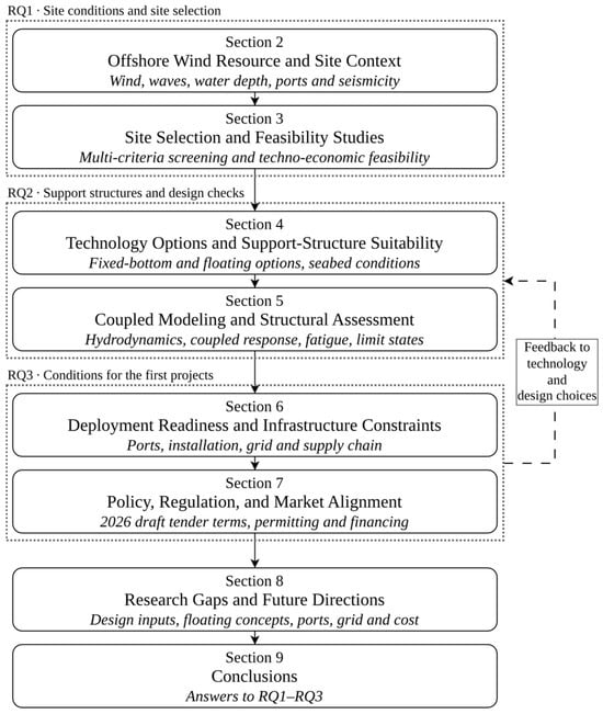
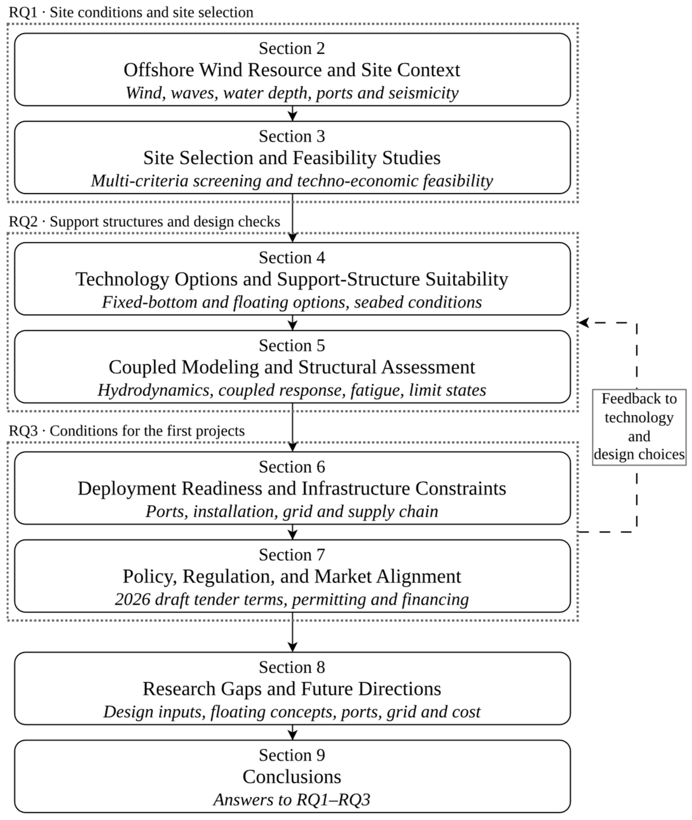
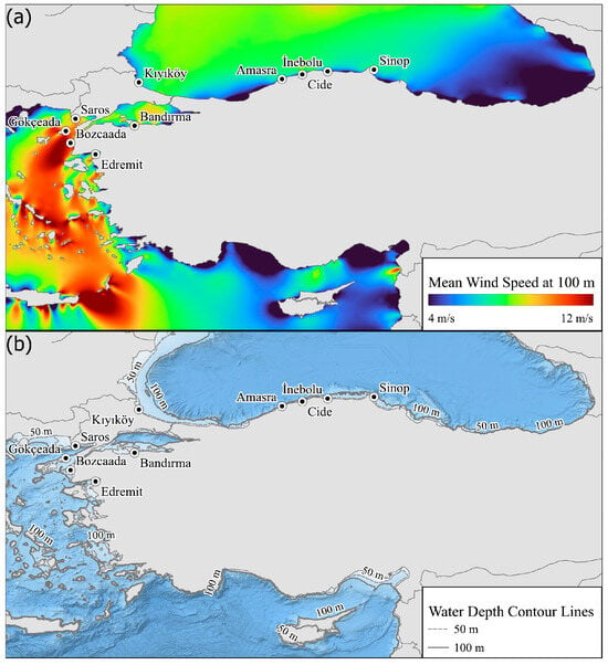
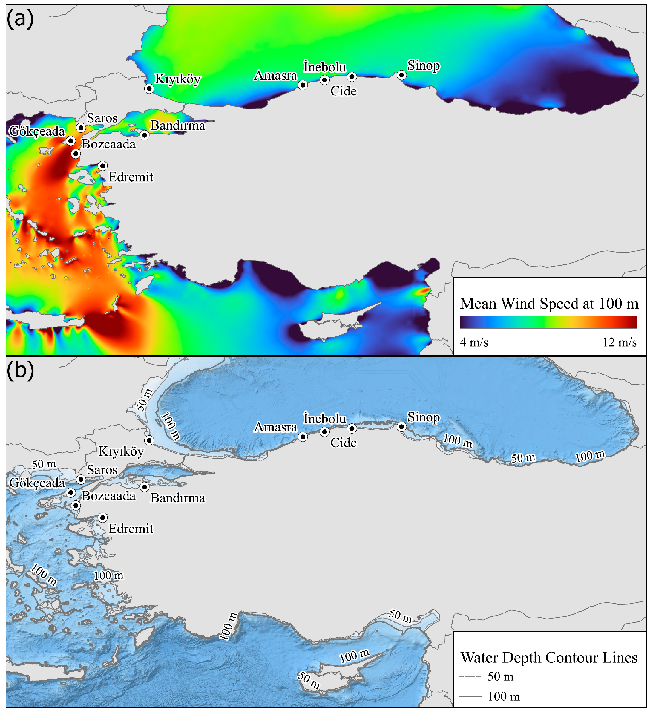
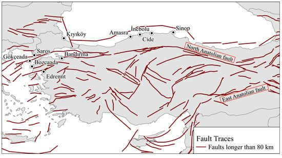
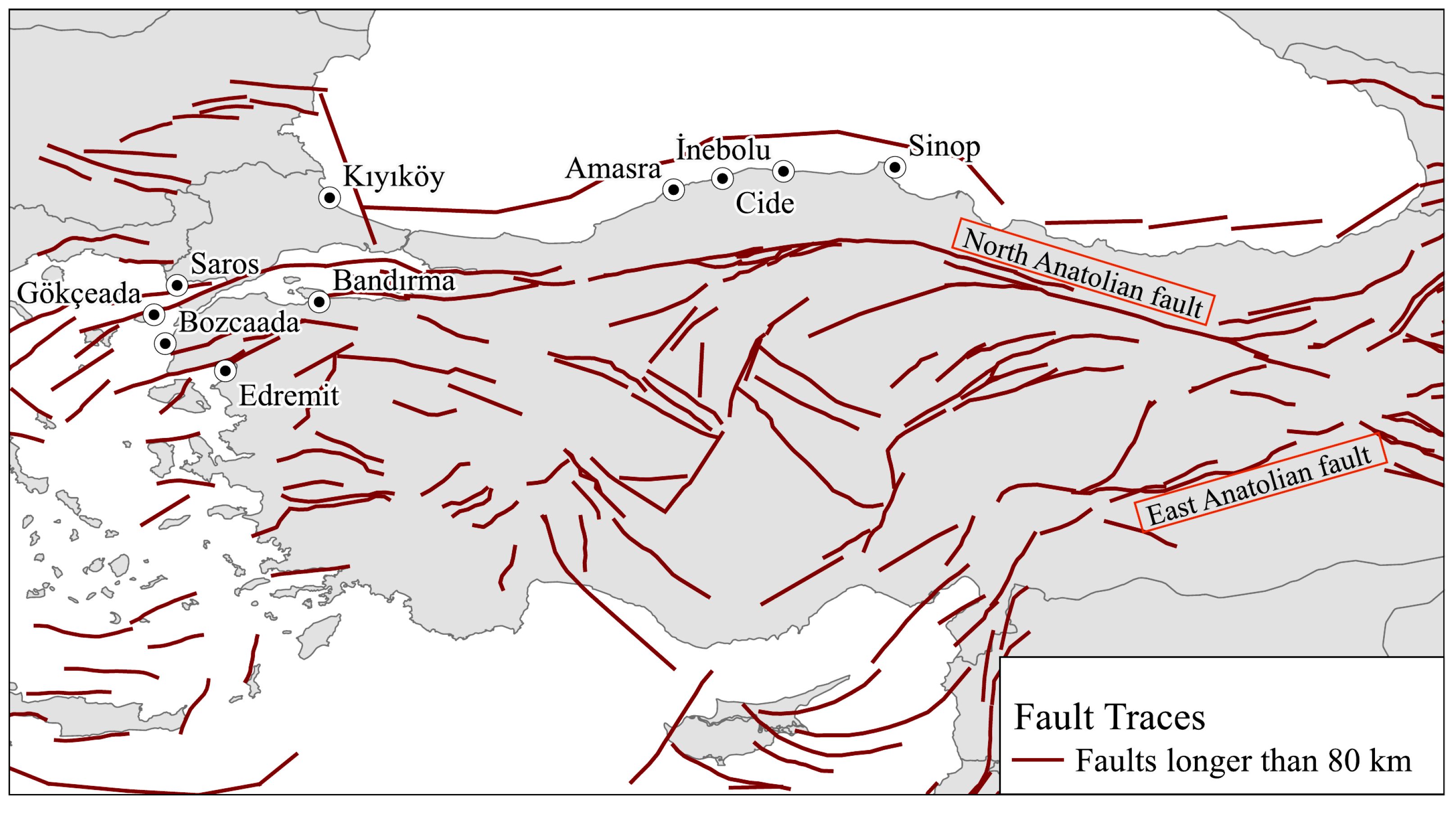
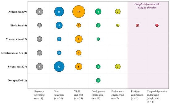
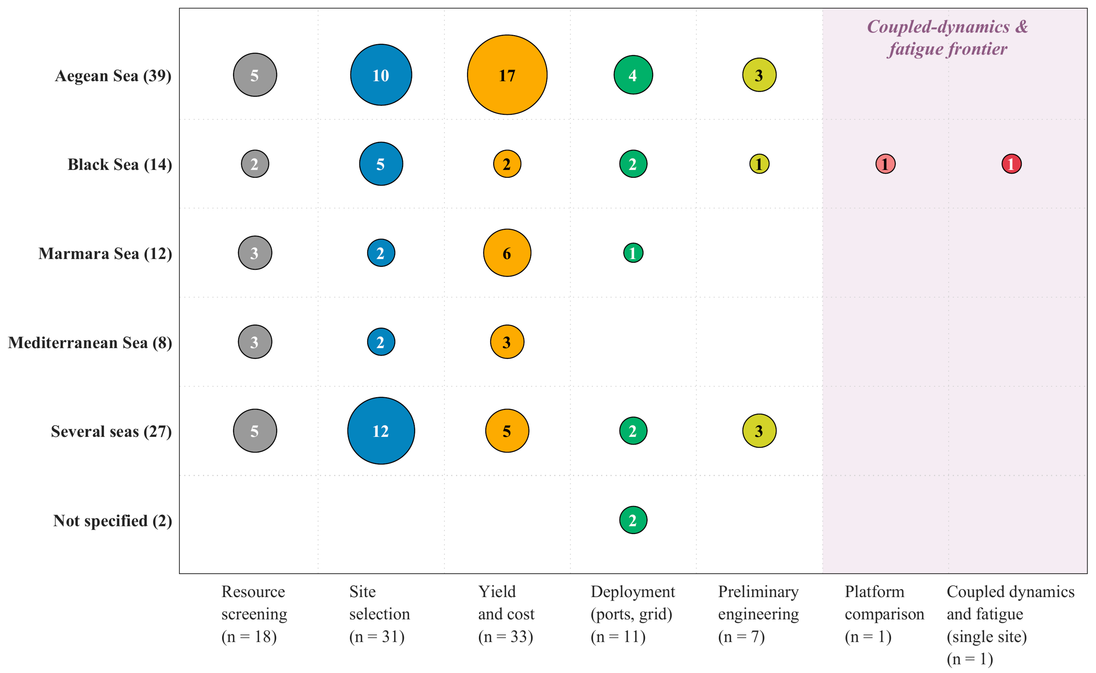
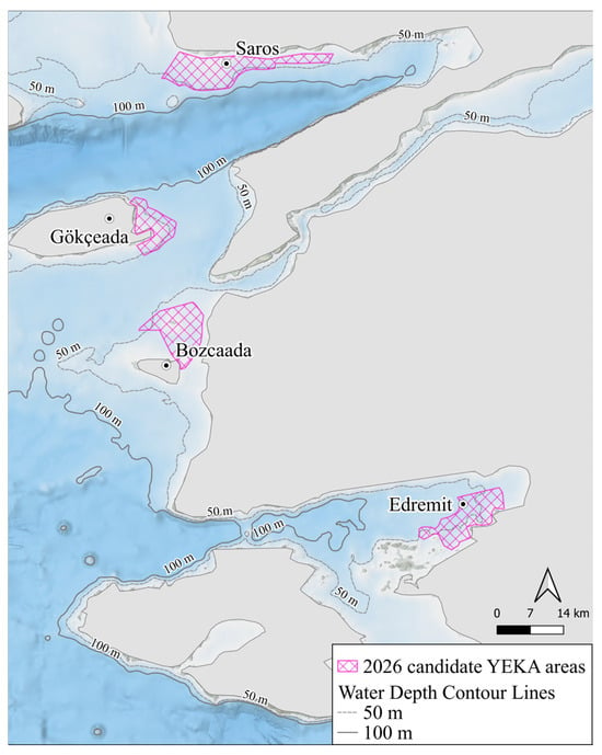
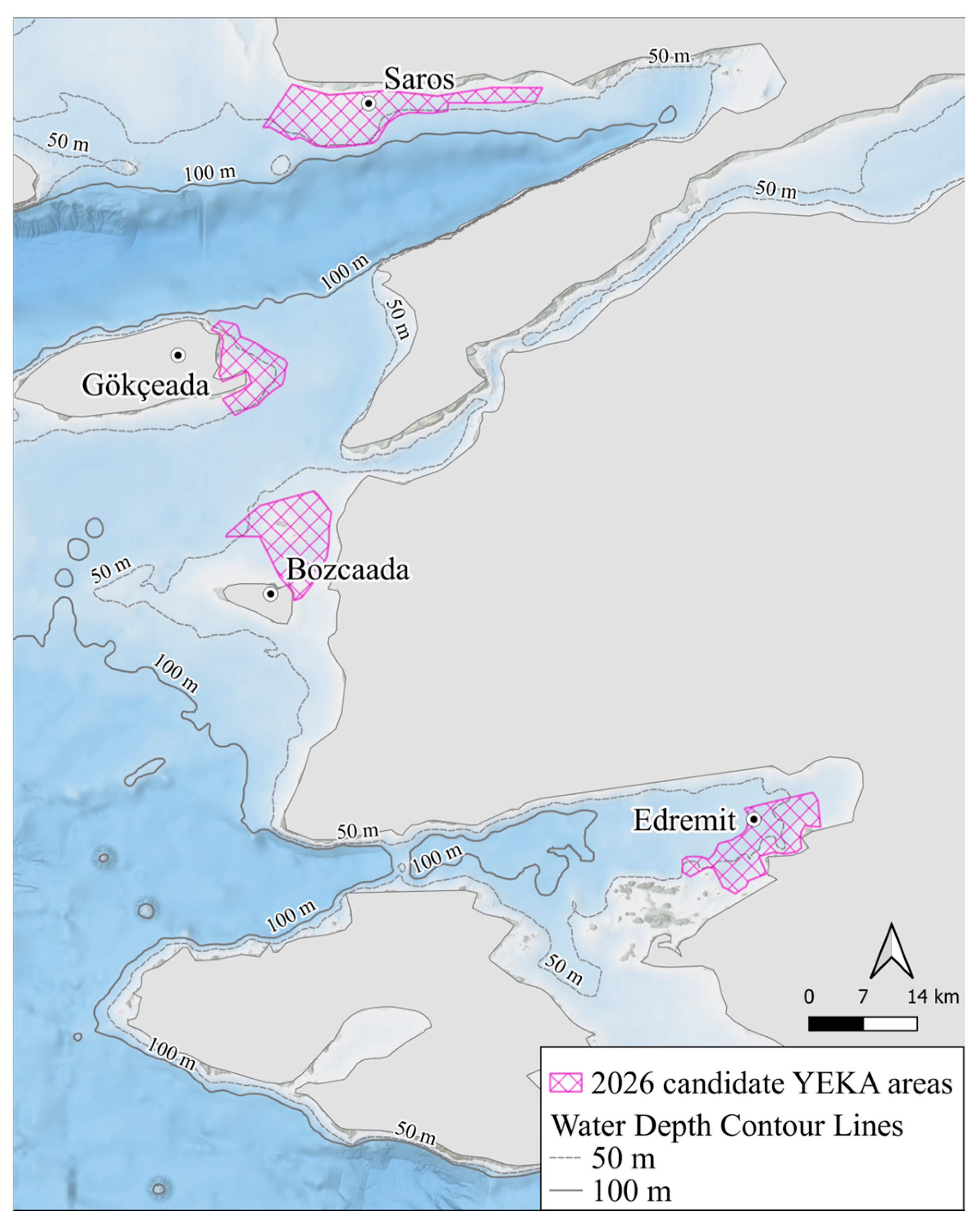

Disclaimer/Publisher’s Note: The statements, opinions and data contained in all publications are solely those of the individual author(s) and contributor(s) and not of MDPI and/or the editor(s). MDPI and/or the editor(s) disclaim responsibility for any injury to people or property resulting from any ideas, methods, instructions or products referred to in the content. |
© 2026 by the authors. Licensee MDPI, Basel, Switzerland. This article is an open access article distributed under the terms and conditions of the Creative Commons Attribution (CC BY) license.