


Abstract
Background: Digital impression technology is widely used in conventional dental fixed restorations and single-unit tooth implant supported fixed restorations, but faces challenges in accurate impressions for multiple implants. The conventional method currently used in clinical practice still requires a large amount of manual operation, long chairside time, and the quality of impression is difficult to guarantee. To overcome these limitations, this study proposed a novel personalized alternative method of impression making for multiple implant-supported fixed restorations based on digital technology and additive manufacturing. Methods: An intraoral scanner was used to obtain 3D data of the impression copings and the surrounding oral soft tissue. A hierarchical structuring was designed using computer-aided design (CAD) software, comprising a novel splinting framework and a corresponding patient-specific custom impression tray. The entire system was fabricated via additive manufacturing. The splinting framework was rigidly connected to the copings using resin, and the tray was guided into position by the splinting framework. The workflow was assessed via an in vitro impression simulation using a four-implant mandibular model and a clinical application in an edentulous patient with three implants. Results: The 3D-printed splinting framework achieved a passive fit in both in vitro and clinical applications. The gap between the splinting framework and copings was effectively filled with resin to establish a rigid connection. The annular step structure accurately guided the custom impression tray to the predetermined vertical position, ensuring uniform impression material thickness. In both the in vitro and the clinical case, the custom tray, splinting framework, and impression copings were removed as a single stable unit without separation or distortion. Conclusions: The proposed CAD-designed, 3D-printed splinting framework combined with a patient-specific custom impression tray demonstrated technical feasibility for multiple implant-supported fixed restorations. It may potentially reduce the face-to-face treatment time and facilitate fast and efficient chairside impression making.
1. Background
The fabrication of accurate fixed restorations for multiple dental implants is critically dependent on the precision of the clinical impression, which must accurately transfer the three-dimensional spatial relationship of the implants to the master cast [1,2]. The conventional open-tray technique with a splinted impression coping is widely considered the gold standard for such cases, as it minimizes distortion caused by polymerization shrinkage of the impression material [3,4]. However, this method is technically sensitive and time-consuming, as it typically necessitates a two-stage impression procedure involving the fabrication of two separate sets of impressions and stone casts. Furthermore, it relies heavily on manual procedures, such as the manual splinting of copings, which can introduce significant errors and compromise patient comfort [5].
The advent of digital dentistry has introduced intraoral scanning (IOS) as a potential alternative to conventional impressions. While IOS has proven to be highly accurate for single-unit restorations, its precision for full-arch or multiple-implant impressions remains a significant challenge [6,7]. The cumulative effect of stitching errors over a large edentulous span can lead to a misfit of the final prosthesis, particularly in cases with non-parallel implants [8,9]. Moreover, the accuracy of intraoral scanning in capturing soft tissue morphology remains suboptimal. Specifically, the dynamic and compressible nature of the oral mucosa often leads to distortions in the digital data, making it particularly challenging to accurately record critical anatomical landmarks such as the mucosal reflection lines. To bridge the gap between conventional and fully digital workflows, hybrid approaches have been proposed. These often involve using digital technology to fabricate patient-specific components, such as custom impression trays or splinting frameworks, via additive manufacturing (3D printing) [10,11].
Recent studies have explored the use of 3D-printed custom trays to standardize the thickness of impression material, which is a known factor influencing accuracy [12]. Furthermore, some digital workflows have incorporated the design and fabrication of splinting frameworks to connect impression copings before the final impression is made [13,14]. For instance, Piedra-Cascón et al. [10] and Li et al. [11] described methods for designing and printing splinted frameworks and custom trays. However, these existing digital workflows still present several limitations. Firstly, some techniques may still require a preliminary conventional impression to fabricate a scan body or a model for the digital design process, which does not fully eliminate the inaccuracies associated with conventional steps. Secondly, the integration between the splinting framework and the custom tray is often not optimized; the tray may not be precisely guided by the framework, potentially leading to uneven pressure on the impression copings during seating. Finally, the design of the custom tray itself may lack features, such as a mesh structure or specific relief areas, that facilitate the escape of excess impression material and prevent voids, which are common issues in conventional tray design.
To address these limitations, this study proposes a novel digital workflow for making impressions for multiple implant-supported fixed restorations. This workflow integrates a hierarchically structured, 3D-printed splinting framework with a corresponding custom impression tray. The term “hierarchical structure” refers to the integration of multiple functional structural levels within the splinting framework, including the coping-retaining cylinders, the annular step structures for vertical positioning, and the connecting splinting framework that provides overall rigidity and stability. The framework is designed not only to rigidly splint the impression copings but also to serve as a precise vertical stop and guide for the custom tray. Compared with the conventional open-tray technique, this integrated design is intended to reduce reliance on manual splinting and facilitates more standardized positioning of the impression copings and tray. Compared with previously reported digital or hybrid workflows, the proposed approach further integrates the splinting framework and custom tray into a coordinated system, allowing the framework to simultaneously provide coping stabilization, vertical control, and tray guidance. This synergistic design is intended to optimize the clinical workflow of the impression procedure by providing a passive fit of the splinted copings, standardizing the impression material thickness, and simplifying the clinical steps. The clinical feasibility of this technique was evaluated through an in vitro simulation and a clinical case report.
2. Methods and Materials
2.1. Digital Data Acquisition
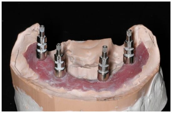
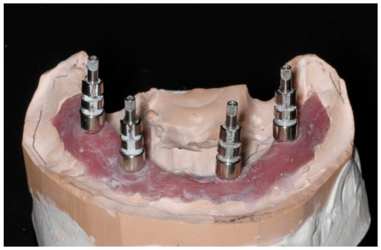
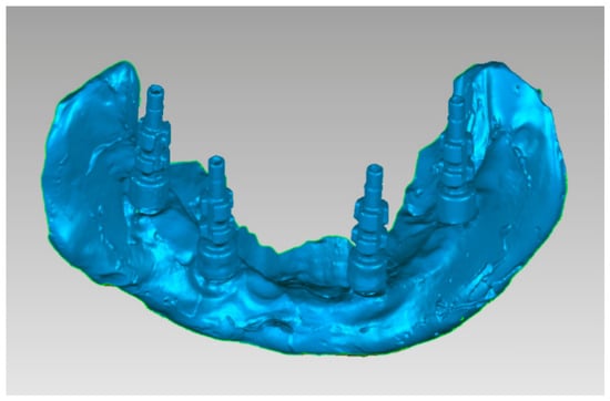
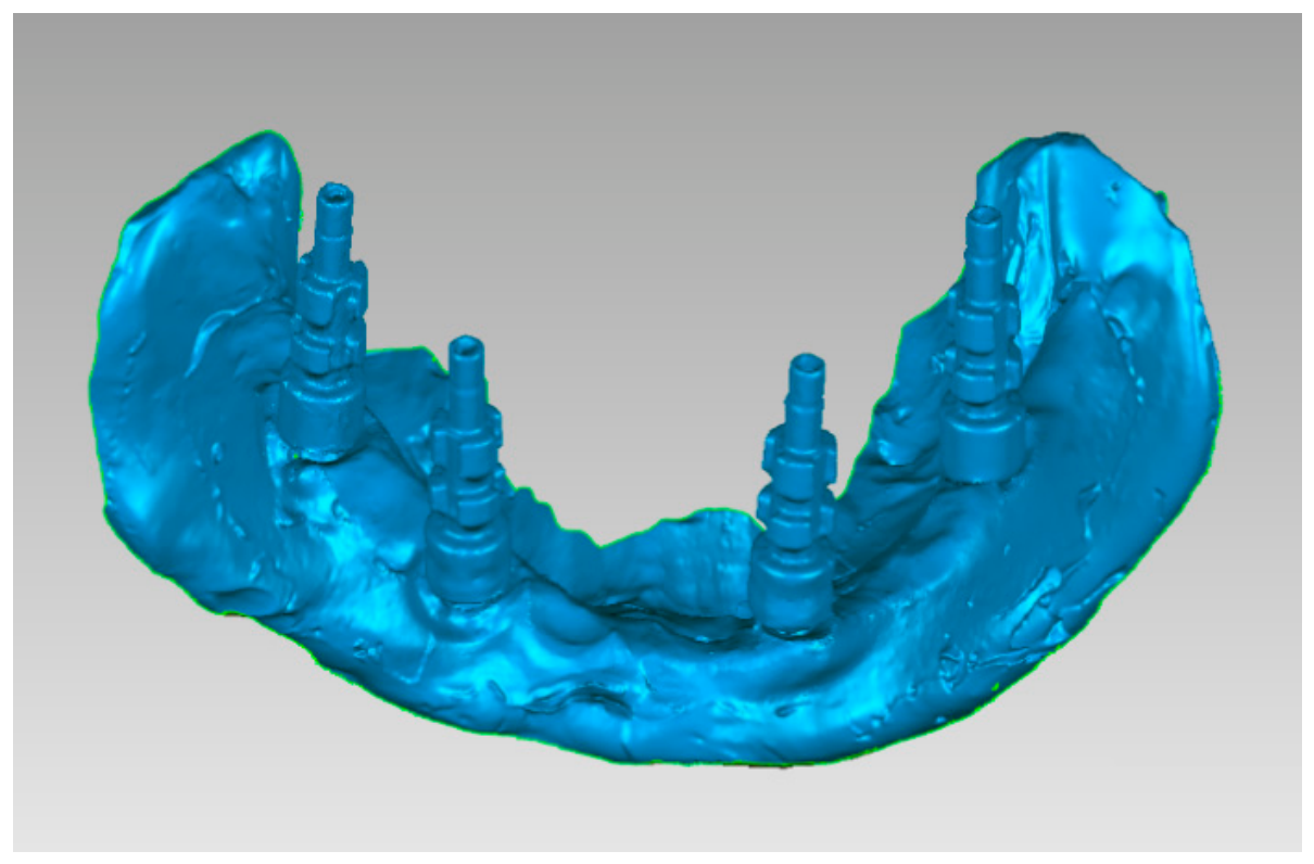
Implant impression copings corresponding to the number of implants were installed onto the implants with screws (Figure 1). An intraoral scanner (CEREC Omnicam, Sirona, Bensheim, Germany) and its corresponding software (CEREC 4.5.2, Sirona, Bensheim, Germany) were used to scan the implant impression copings and the surrounding oral soft tissue (Figure 2). Digital impressions were acquired by scanning the implant scan bodies in a sequential ‘zigzag’ pattern across the arch to minimize cumulative errors. Cross-arch scans were subsequently performed to ensure the accurate spatial registration of the implant positions [15]. The obtained 3D point cloud data were then exported as Standard Tessellation Language (STL) files (denoted as DATA I).
Figure 1.
Mandibular implant model with impression coping installed.
Figure 2.
The three-dimensional digital implanting model.
2.2. Design of the Splinting Framework
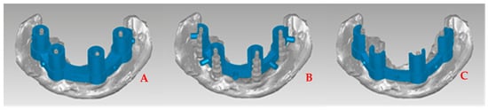
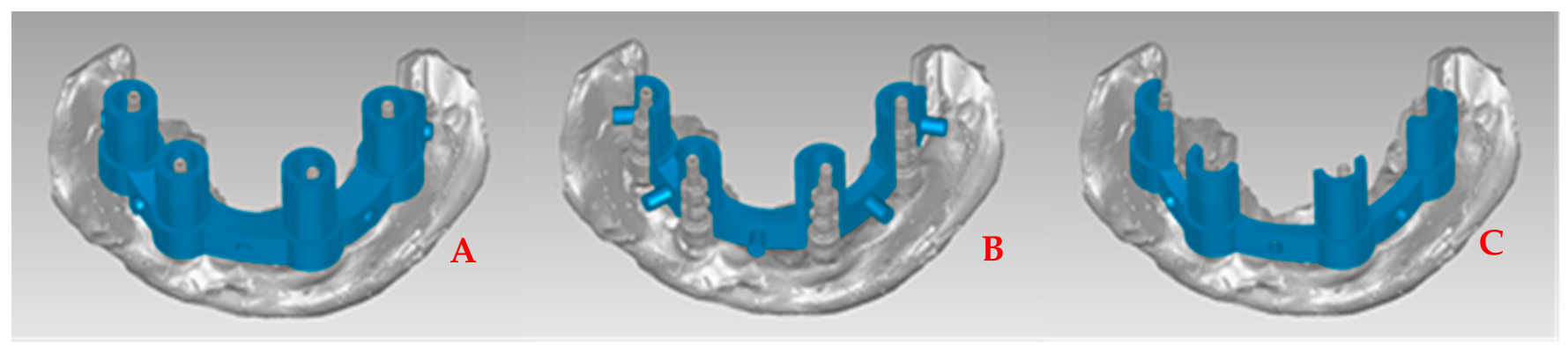
The DATA I file was imported into 3D CAD software (SolidWorks 2016, Dassault Systèmes, Vélizy-Villacoublay, France) to design the splinting framework. Based on the size and shape of the impression copings, cylindrical sleeves were designed with a height matching the coping length and a wall thickness of 1 mm to provide adequate the minimum sufficient mechanical strength for the resin splint. The lower half of the cylinders was thickened by 1 mm relative to the upper half, creating an external annular step to support the impression tray. To facilitate passive seating, the inner diameter was set 1 mm larger than the maximum cross-sectional dimension of the copings. These cylinders were bridged by curved rods (6 mm in width and 4 mm in thickness) located at the vertical center of the cylinder walls [16]. The designed length of each curved rod was adapted to the distance between the impression copings. A 3 mm clearance was reserved between the bottom surfaces of all cylinders and the alveolar crest to accommodate impression material [17]. Finally, the structure was bisected into buccal and lingual sections along the central arc, incorporating a cylindrical bolt and a matching bolt passage at the center of each connecting rod for reassembly. The buccal and lingual components were saved as STL files (Figure 3).
Figure 3.
Three-dimensional designing of the splinting framework for multiple impression copings. (A) The whole splinting framework; (B) the lingual part of the splinting framework; (C) the buccal part of the splinting framework.
2.3. Design of the Custom Impression Tray
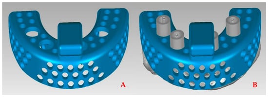
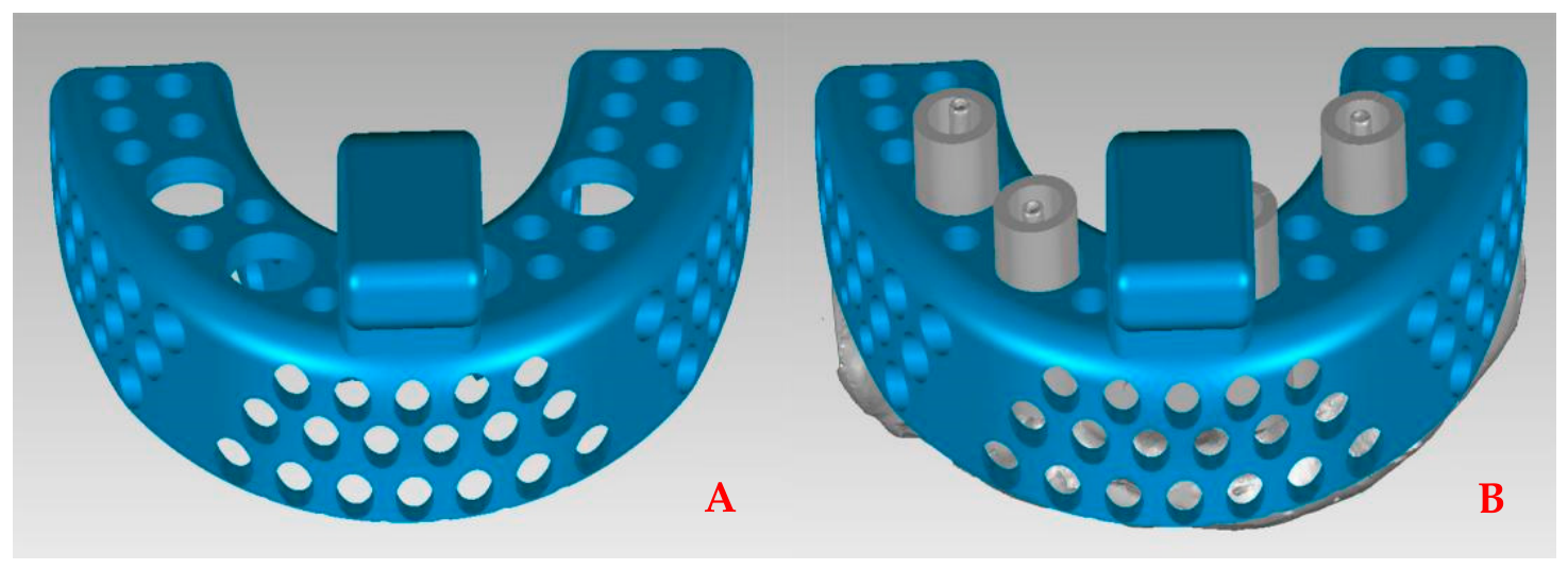
The custom impression tray for the mandibular arch was designed using SolidWorks, following general fabrication standards for removable denture custom trays. The basal surface of the tray was adapted to the contour of the alveolar ridge. The tray width was designed to be 3 mm wider than the ridge, while the peripheral borders were positioned 3 mm away from the mucosal folds [17]. The posterior margin was extended to cover the retromolar pad, and a uniform tray thickness of 3 mm was adopted [17]. Additionally, an anterior handle was designed on the outer surface of the tray to aid in placement and removal. To enable integration with the splinting framework, circular openings corresponding to the number of impression copings were created on the bottom surface of the tray. The diameter of these openings was designed to correspond to the outer diameter of the upper half of the framework cylinders, allowing the tray to seat appropriately onto the annular steps. Finally, the design data were exported in STL format (Figure 4).
Figure 4.
Three-dimensional designing of the custom impression tray. (A) Three-dimensional picture of custom impression tray; (B) three-dimensional picture of custom impression tray placed on cast with splinting framework.
2.4. Fabrication of the Splinting Framework and Custom Tray
The three STL datasets were fabricated using a desktop 3D printer (Objet30 Pro, Stratasys Ltd., Eden Prairie, MN, USA) utilizing PolyJet technology with a layer thickness of 28 μm. The splinting framework (buccal and lingual parts) and the custom impression tray were printed using a clear rigid photopolymer (VeroClear, Stratasys, Ltd., Eden Prairie, MN, USA), with water-soluble support material (Support705™). Post-processing involved removing the support material in an alkaline solution bath, followed by air drying to obtain the final prototypes (Figure 5A).
Figure 5.
The splinting framework and custom impression tray for multiple impression copings. (A) The three-dimensional printed splinting framework and custom impression tray; (B) the splinting framework was placed on cast; (C) the custom impression tray was placed on the cast with splinting framework.
2.5. Impression Making
The clinical feasibility of the workflow was evaluated through both an in vitro simulation and clinical patient application. The procedure was standardized as follows:
First, the splinting framework was seated onto the impression copings, confirming a passive fit. The gap between the internal surface of the cylinders and the impression copings was then filled with flowable resin and cured to rigidly connect the system.
Subsequently, impression material was dispensed into the custom tray. The tray was seated into the patient’s mouth (or on the model), accurately guided by the framework cylinders until it rested on the designed annular steps. Upon complete setting of the impression material, the impression copings were unscrewed from the implants. Finally, the entire assembly—consisting of the custom tray, the splinting framework, and the impression copings—was removed as a single unit.
3. Results
3.1. In Vitro Impression Simulation
A preliminary try-in was performed on the mandibular cast with four implants. The splinting framework achieved a passive fit around the impression copings without interference. A uniform gap was observed between the inner surface of the cylindrical sleeves and the impression copings, which facilitated the injection and containment of the flowable resin. The annular step structure on the framework cylinders successfully functioned as a vertical stop. It guided the custom impression tray into the predetermined position, ensuring the designed uniform thickness of the impression material. This verification confirmed the geometric fit and passive seating of the system (Figure 5).
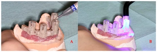
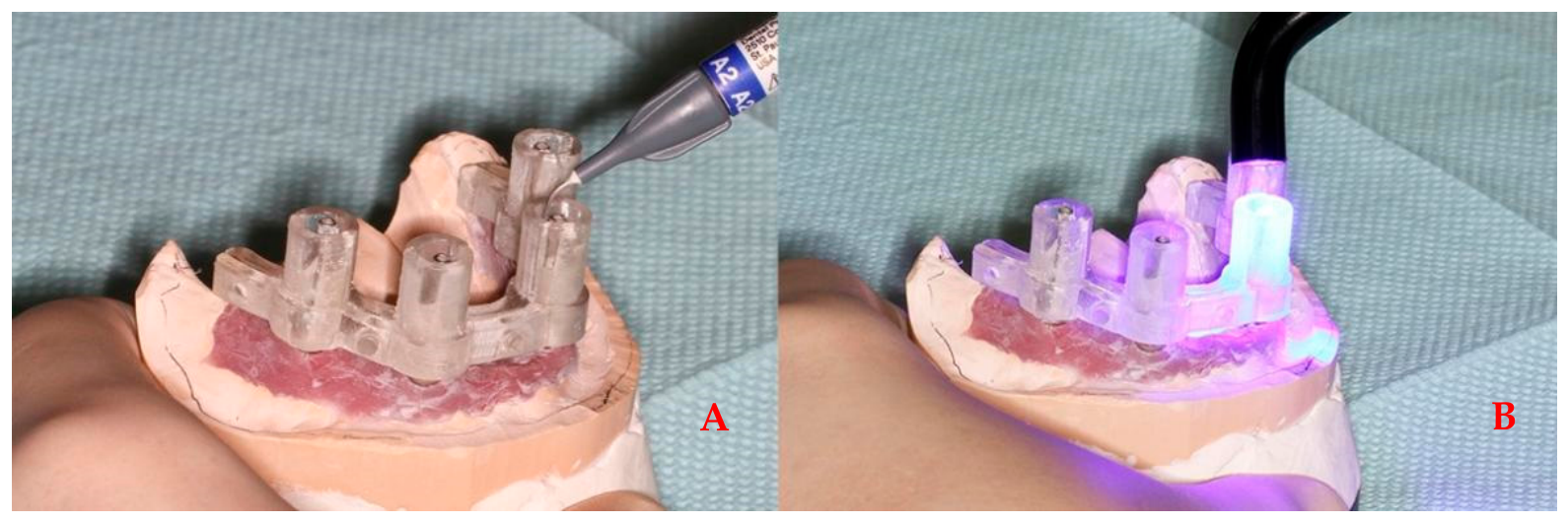
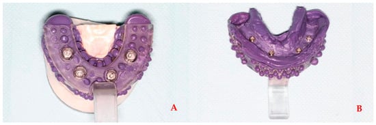
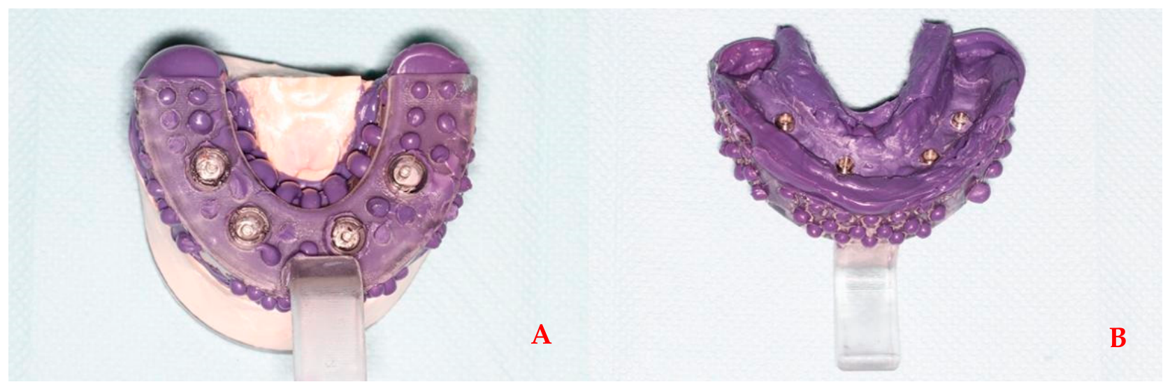
In the simulated impression process, the splinting framework was seated along the impression copings in the mandibular cast. The gap between the inner surface of the framework cylinders and the impression copings was filled with flowable resin. After light curing, the resin rigidly connected the splinting framework to the copings (Figure 6). The custom impression tray containing the impression material was seated along the guidance of the cylinders until it reached the designed step position (Figure 7A). After the material solidified, the impression copings were unscrewed, and the splinting framework, custom tray, and impression copings were removed as a single unit without separation or distortion (Figure 7B).
Figure 6.
Rigid fixation of the splinting framework to the impression copings. (A) Controlled clearance between the inner surface of the framework cylinder and the impression coping before resin application; (B) the gap filled with flowable resin and polymerized to establish a rigid connection.
Figure 7.
Guided seating and integrated removal of the impression assembly in the in vitro simulation. (A) The custom impression tray with impression material was seated along the cylinder. (B) The custom impression tray and the splinting framework were removed as a whole.
3.2. Clinical Application
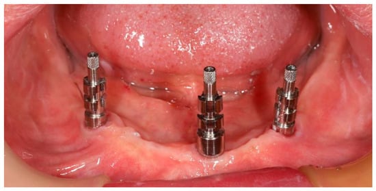
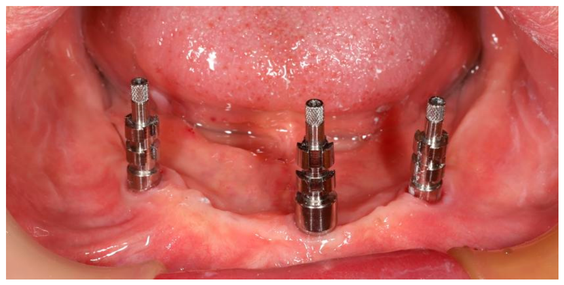
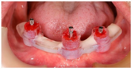
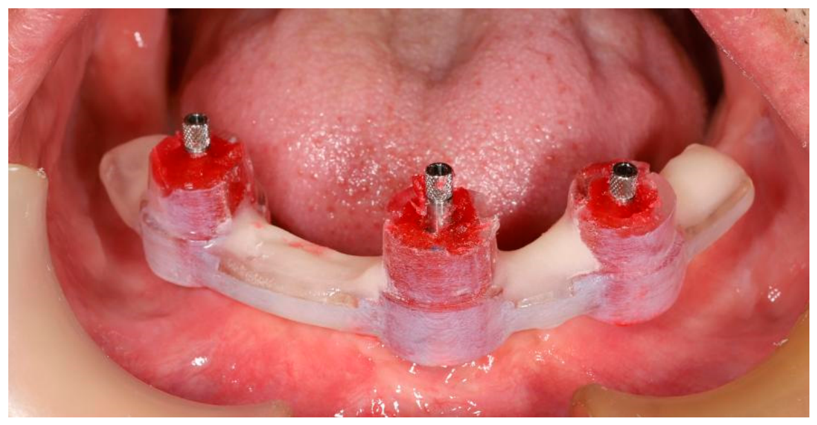
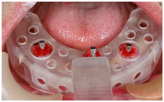
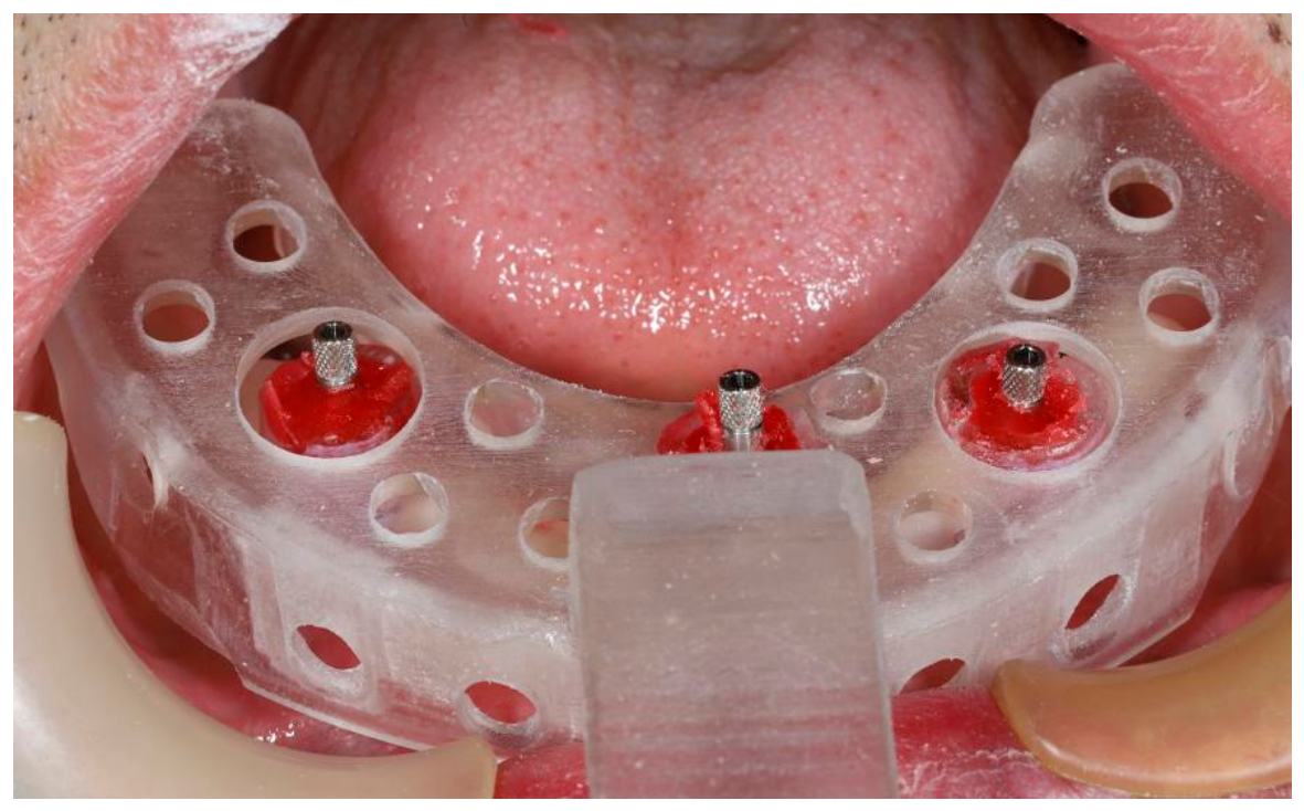
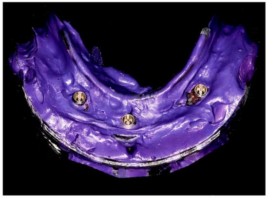
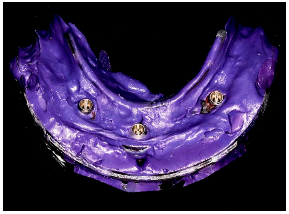
The proposed technique was successfully applied in a clinical case involving an edentulous patient with three mandibular implants (Figure 8). Abutment pick-ups were placed on the implants for taking an abutment-level impression. The 3D-printed splinting framework was successfully seated intraorally on the abutment pick-ups, confirming that the splinting framework could be passively seated in the oral environment. The gap between the inside of the cylinder and the impression coping was filled with flowable resin and self-curing resin to ensure a rigid connection (Figure 9). The custom impression tray was then seated along the guidance of the cylinders. The ring-shaped step structure effectively guided the tray to the predetermined vertical position, maintaining a 3 mm clearance between the bottom surface and the alveolar crest for the impression material (Figure 10). Upon complete setting of the Polyether rubber impression material (3M ESPE, USA), the pick-up copings were unscrewed, and the assembly was removed as a single unit. Visual inspection of the final impression confirmed a smooth surface free of voids or defects, verifying the stable transfer of the implant positions for the subsequent fabrication of the fixed prosthesis (Figure 11).
Figure 8.
Three implants (DENTSPLY SIRONA, ASTRA TX) were placed in the lower jaw for a fixed full arch restoration. The implants were attached with 20° UniAbutment, then abutment pick-up was placed for taking an abutment level impression.
Figure 9.
Clinical seating and rigid fixation of the 3D-printed splinting framework. The splinting framework was passively seated on the abutment pick-up impression copings, and the controlled clearance between the framework cylinders and copings was filled with flowable and self-curing resin to establish a rigid connection.
Figure 10.
Guided positioning of the patient-specific custom impression tray in the clinical case. The tray was seated along the framework cylinders until reaching the annular step, which established the predetermined vertical position and maintained the designed space for impression material.
Figure 11.
Final impression obtained using the proposed workflow. The custom tray, splinting framework, and impression copings were removed as a single integrated unit after setting of the impression material.
4. Discussion
Accurate transfer of the spatial relationship among multiple implants is essential for the fabrication of a well-fitting fixed prosthesis. The conventional open-tray impression technique with splinted impression copings remains a reliable approach for multiple-implant impressions because the copings can be rigidly connected before impression making [18]. However, this technique is highly dependent on manual procedures, including coping splinting and tray positioning, and may require relatively lengthy chairside manipulation. In the present study, the proposed workflow provided a more integrated approach by combining digitally designed splinting, tray positioning, and conventional impression making. The relatively streamlined chairside procedure observed in the present study may therefore be attributed primarily to workflow integration rather than to digital fabrication alone. Once the splinting framework was rigidly connected to the impression copings, the custom tray could be positioned directly along the framework without the need for extensive manual adjustment.
An important advantage of the proposed workflow is that it combines selected advantages of digital and conventional impression techniques rather than attempting to replace the conventional impression procedure with intraoral scanning alone. Digital data acquisition and CAD-based fabrication allow patient-specific components to be designed according to the three-dimensional anatomy and implant positions, while reducing reliance on conventional physical models during the design stage. However, fully digital intraoral scanning remains challenging for extensive multiple-implant cases because scanning accuracy may be affected by saliva, bleeding, limited intraoral visibility, and the accumulation of stitching errors over long edentulous spans. Therefore, the present workflow uses intraoral scanning primarily as the basis for digital design, while the definitive implant-position transfer is still achieved with an elastomeric impression [19]. In this respect, the proposed technique may be regarded as a hybrid workflow that retains the positional stability of a conventional splinted impression while incorporating the customization and preclinical preparation advantages of digital technology.
Previous studies by Piedra-Cascón et al. [10] and Li et al. [11] demonstrated the feasibility of using digital workflows to fabricate splinting frameworks and custom impression trays for multiple implants. The present technique further develops this concept by integrating the splinting framework and custom tray into a coordinated, hierarchically structured system. Here, the hierarchical structure consists of multiple functional levels within the framework: the cylinders retain and stabilize the impression copings, the annular step structures provide vertical positioning and tray support, and the connecting framework provides overall rigidity and maintains the spatial relationship among the copings. The annular step structure is particularly important because it functions as a predetermined vertical stop for the custom tray. Once the tray reaches the annular steps, a defined space for impression material is maintained, thereby helping to reduce variations in impression material thickness and limit positional changes during tray seating. This design differs from workflows in which the splinting framework and custom tray function more independently and may require additional manual adjustment during tray positioning. The mechanical coordination of these components may therefore contribute to the stability and reproducibility observed in the present study.
The passive seating strategy of the splinting framework provides a further engineering basis for maintaining the implant relationship. Because intraoral scanning, virtual design, and additive manufacturing may introduce small dimensional deviations, an excessively tight fit between the printed framework and impression copings could cause interference during seating and potentially alter the intended coping position. In the present design, the inner diameter of the framework cylinders was intentionally made 1 mm larger than the maximum cross-sectional dimension of the impression copings, providing controlled clearance for passive seating. After the framework was positioned, the clearance was filled with resin and polymerized to establish a rigid connection. Thus, positioning and fixation were functionally separated: the clearance allowed passive seating despite minor fabrication deviations, whereas the cured resin stabilized the copings after their intended positions had been established. This error-tolerant design may reduce the transfer of cumulative digital fabrication errors to the impression. Importantly, the feasibility of this strategy was supported by the present in vitro and clinical observations. In both settings, the splinting framework could be passively seated, and the custom tray, splinting framework, and impression copings were subsequently removed as a single stable unit without visible separation or distortion. In the clinical case, the definitive prosthesis showed satisfactory clinical fit during the try-in procedure. Although these observations provide preliminary evidence supporting the ability of the workflow to maintain implant positional relationships, they should not be interpreted as definitive evidence of superior dimensional accuracy because the present study was not designed as a quantitative comparative clinical trial.
From a clinical perspective, successful application of the proposed workflow depends not only on the structural design but also on appropriate clinical execution. Adequate exposure of the impression copings is required to allow unobstructed seating of the splinting framework, while effective moisture control is important for maintaining clear visualization and reliable resin bonding. Stable rigid fixation between the framework and impression copings must be achieved before tray placement, and the tray should be fully seated against the annular steps to establish the intended vertical position. When these conditions are properly controlled, the framework and tray can function as an integrated unit during impression making and removal.
The practical efficiency of the workflow should nevertheless be considered together with its clinical advantages. Unlike a conventional impression procedure, the proposed approach requires preliminary digital scanning, CAD, and 3D printing of patient-specific components. These steps require additional preparation time and require access to digital design and additive-manufacturing equipment. However, most of this preparation can be completed before the clinical appointment and does not require prolonged chairside manipulation. Thus, the potential practical benefit of the proposed technique is not necessarily a reduction in the total time required for the entire workflow, but a reduction in the complexity and manual workload of the clinical impression procedure. This distinction is important when considering the technique as an alternative to conventional multiple-implant impressions.
Limitations and Future Directions
This study presents a proof-of-concept engineering demonstration of digital impressions for multiple implant-supported fixed restorations, highlighting its potential clinical relevance. However, several limitations inherent to the current stage of development must be acknowledged. First, the findings are primarily based on qualitative observations and technical feasibility assessments, rather than rigorous quantitative validation or statistical analysis. Consequently, the results should be interpreted as an initial engineering verification of the proposed methodology, not as definitive clinical evidence. Second, the custom tray was designed with the incorporation of circular openings under the assumption that all placed implants were parallel; therefore, the method described in this study cannot be applied to cases involving posterior tilted implants. Third, the absence of a large-scale, controlled clinical trial means that the generalizability of our observations to broader patient populations remains to be established. The current work serves as a foundational step demonstrating technical viability, but further research involving quantitative data collection, comparative clinical studies, and specific investigations into computer-aided impression technology for angulated posterior implants is necessary to fully validate the efficacy, reliability, and broader applicability of the proposed approach.
5. Conclusions
Based on the integration of intraoral digital scanning, CAD, and additive manufacturing, this study proposed a hierarchical workflow consisting of a splinting framework and a custom tray. The in vitro simulation and clinical application demonstrated the technical and clinical feasibility of this personalized alternative method for making impressions of multiple implant-supported fixed restorations. Further quantitative studies with larger sample sizes are required to validate its objective accuracy and clinical efficiency compared to conventional techniques.
Author Contributions
S.L.: Methodology, Investigation, Data curation, Writing—original draft preparation; D.L.: Investigation, Writing—original draft preparation; Q.Z.: Data curation, Writing—review and editing; F.Y. and L.J.: Methodology, Investigation; G.Y.: Conceptualization, Resources, Writing—review and editing. All authors have read and agreed to the published version of the manuscript.
Funding
This study was supported by the Innovative Clinical Technologies and Therapies Program of Peking University Hospital of Stomatology [Grant number PKUSSNCT-24B12]; National Natural Science Foundation of China [Grant number 82371019, 82301160]; the Beijing Natural Science Foundation [Grant number L232098]; the National Key Research and Development Program of China [Grant number 2020YFB1312800]; the Foundation of State Key Laboratory for Advanced Metals and Materials [Grant number 2023-Z03]; the Peking University Medicine Fund for World’s Leading Discipline or Discipline Cluster Development [Grant number BMU2022XKQ003]; and the Peking University Clinical Scientist Training Program [Grant number BMU2023PYJH019], Clinical Research Foundation of Peking University School and Hospital of Stomatology [Grant number PKUSS-2023CRF209], and Beijing Natural Science Foundation [Grant number 7174364].
Institutional Review Board Statement
The study was conducted in accordance with the Declaration of Helsinki, and approved by the Biomedical Ethics Committee of Peking University School and Hospital of Stomatology in China (protocol code PKUSSIRB-201627041 and date of approval 14 July 2016).
Informed Consent Statement
Informed consent was obtained from all subjects involved in the study. Written informed consent has been obtained from the patient to publish this paper.
Data Availability Statement
The trial protocol, and data supporting the findings of this study are available from the corresponding author upon request.
Conflicts of Interest
The authors declare no conflicts of interest.
References
- Flügge, T.; van der Meer, W.J.; Gonzalez, B.G.; Vach, K.; Wismeijer, D.; Wang, P. The accuracy of different dental impression techniques for implant-supported dental prostheses: A systematic review and meta-analysis. Clin. Oral Implant. Res. 2018, 29, 374–392. [Google Scholar] [CrossRef] [Scilit] [PubMed]
- Kim, J.E.; Kwon, D.H.; Kim, J.H.; Shim, J.S. A digital implant custom tray fabrication method using the design process for simulating the position of the impression copings and 3D printing technology. J. Prosthet. Dent. 2019, 121, 566–570. [Google Scholar] [CrossRef] [Scilit] [PubMed]
- Rutkunas, V.; Ignatovic, J. A technique to splint and verify the accuracy of implant impression copings with light-polymerizing acrylic resin. J. Prosthet. Dent. 2014, 111, 254–256. [Google Scholar] [CrossRef] [Scilit] [PubMed]
- Chochlidakis, K.; Papaspyridakos, P.; Tsigarida, A.; Romeo, D.; Chen, Y.W.; Natto, Z.; Ercoli, C. Digital Versus Conventional Full-Arch Implant Impressions: A Prospective Study on 16 Edentulous Maxillae. J. Prosthodont. 2020, 29, 281–286. [Google Scholar] [CrossRef] [Scilit] [PubMed]
- Millstein, P.; Maya, A.; Segura, C. Determining the accuracy of stock and custom tray impression/casts. J. Oral Rehabil. 1998, 25, 645–648. [Google Scholar] [CrossRef] [Scilit] [PubMed]
- Kanazawa, M.; Iwaki, M.; Arakida, T.; Minakuchi, S. Digital impression and jaw relation record for the fabrication of CAD/CAM custom tray. J. Prosthodont. Res. 2018, 62, 509–513. [Google Scholar] [CrossRef] [Scilit] [PubMed]
- An, X.; Yang, H.W.; Choi, B.H. Digital Workflow for Computer-Guided Implant Surgery in Edentulous Patients with an Intraoral Scanner and Old Complete Denture. J. Prosthodont. 2019, 28, 715–718. [Google Scholar] [CrossRef] [Scilit] [PubMed]
- Alsharbaty, M.H.M.; Alikhasi, M.; Zarrati, S.; Shamshiri, A.R. A Clinical Comparative Study of 3-Dimensional Accuracy between Digital and Conventional Implant Impression Techniques. J. Prosthodont. 2019, 28, e902–e908. [Google Scholar] [CrossRef] [Scilit] [PubMed]
- Lee, J.H. Fabricating a custom tray for an impression of multiple abutment teeth by using an open-source software program. J. Prosthet. Dent. 2021, 125, 576–580. [Google Scholar] [CrossRef] [Scilit] [PubMed]
- Piedra Cascón, W.; Revilla-León, M. Digital workflow for the design and additively manufacture of a splinted framework and custom tray for the impression of multiple implants: A dental technique. J. Prosthet. Dent. 2018, 120, 805–811. [Google Scholar] [CrossRef] [Scilit] [PubMed]
- Li, J.; Chen, Z.; Dong, B.; Wang, H.L.; Yu, H. A digital workflow with computer-assisted implant planning for fabricating an impression splinting framework and custom tray for multiple implants. J. Prosthet. Dent. 2020, 124, 262–269. [Google Scholar] [CrossRef] [Scilit] [PubMed]
- Yang, X.; Liu, Y.; Li, Y.; Zhao, Y.; Di, P. Accuracy and feasibility of 3D-printed custom open trays for impressions of multiple implants: A self-controlled clinical trial. J. Prosthet. Dent. 2022, 128, 396–403. [Google Scholar] [CrossRef] [Scilit] [PubMed]
- Rutkunas, V.; Bilius, V.; Simonaitis, T.; Auskalnis, L.; Jurgilevicius, J.; Akulauskas, M. The effect of different implant impression splinting techniques and time on the dimensional accuracy: An in vitro study. J. Dent. 2022, 126, 104267. [Google Scholar] [CrossRef] [Scilit] [PubMed]
- Palantza, E.; Sykaras, N.; Zoidis, P.; Kourtis, S. In vitro comparison of accuracy between conventional and digital impression using elastomeric materials and two intra-oral scanning devices. J. Esthet. Restor. Dent. 2024, 36, 1179–1198. [Google Scholar] [CrossRef] [Scilit] [PubMed]
- Papaspyridakos, P.; De Souza, A.; Finkelman, M.; Sicilia, E.; Gotsis, S.; Chen, Y.W.; Vazouras, K.; Chochlidakis, K. Digital vs Conventional Full-Arch Implant Impressions: A Retrospective Analysis of 36 Edentulous Jaws. J. Prosthodont. 2023, 32, 325–330. [Google Scholar] [CrossRef] [Scilit] [PubMed]
- Saini, H.S.; Jain, S.; Kumar, S.; Aggarwal, R.; Choudhary, S.; Reddy, N.K. Evaluating the Effect of Different Impression Techniques and Splinting Methods on the Dimensional Accuracy of Multiple Implant Impressions: An in vitro Study. J. Contemp. Dent. Pract. 2018, 19, 1005–1012. [Google Scholar] [CrossRef] [Scilit] [PubMed]
- Sun, Y.; Chen, H.; Li, H.; Deng, K.; Zhao, T.; Wang, Y.; Zhou, Y. Clinical evaluation of final impressions from three-dimensional printed custom trays. Sci. Rep. 2017, 7, 14958. [Google Scholar] [CrossRef] [Scilit] [PubMed]
- Papaspyridakos, P.; Chen, C.J.; Gallucci, G.O.; Doukoudakis, A.; Weber, H.P.; Chronopoulos, V. Accuracy of implant impressions for edentulous jaws: A systematic review. Int. J. Oral Maxillofac. Implant. 2014, 29, 836–845. [Google Scholar] [CrossRef] [Scilit] [PubMed]
- Revilla-León, M.; Meyer, M.J.; Zandinejad, A.; Özcan, M. Additive manufacturing technologies for fabricating custom impression trays: A review. J. Prosthodont. 2019, 28, e870–e877. [Google Scholar]


Disclaimer/Publisher’s Note: The statements, opinions and data contained in all publications are solely those of the individual author(s) and contributor(s) and not of MDPI and/or the editor(s). MDPI and/or the editor(s) disclaim responsibility for any injury to people or property resulting from any ideas, methods, instructions or products referred to in the content. |
© 2026 by the authors. Licensee MDPI, Basel, Switzerland. This article is an open access article distributed under the terms and conditions of the Creative Commons Attribution (CC BY) license.