


Abstract
To satisfy the requirements of voltage support and fault-current limitation for electric-vehicle (EV) charging stations connected to weak distribution networks, an increasing number of charging infrastructures are adopting grid-forming (GFM) converters and vehicle-to-grid (V2G) control strategies. Under AC short-circuit faults and voltage-sag conditions, limiting the fault current injected by the converter is essential to reduce overcurrent risk to power semiconductor devices. For this, an adaptive virtual-impedance-based low-voltage ride-through (LVRT) method is proposed for GFM converters in EV charging stations. First, an overcurrent grading criterion is constructed based on real-time current measurements. In the moderate-overcurrent region, an adaptive virtual reactance is introduced to achieve soft current limiting. In the severe-overcurrent region, hard current limiting is implemented by further increasing the virtual reactance and blocking overcurrent bridge arm. In addition, a virtual-reactance recovery mechanism is designed to ensure smooth post-fault restoration. Based on an RCP + HIL platform, experiments are conducted to validate the proposed fault current-limiting method. Experiment results demonstrate that the proposed method can rapidly suppress fault current, maintain voltage-support capability, and shorten post-fault restoration time.
1. Introduction
In recent years, the rapid growth in electric-vehicle (EV) adoption has accelerated the deployment of high-power charging stations in industrial parks, transportation hubs, and highway service areas [1,2]. Compared with conventional dispersed loads, high-power charging stations are characterized by high power density and diverse operating modes. Their points of connection are often located at the end of feeders or at buses with limited short-circuit capacity, which may aggravate voltage fluctuations, weaken transient voltage support, and complicate protection coordination [3,4]. To address these issues, in the coordinated “charging station–energy storage–vehicle” scenario, upgrading the grid-connected converters in charging stations from grid-following (GFL) control to grid-forming (GFM) control can provide reactive power–voltage support under weak-grid conditions.
However, short-circuit faults or voltage sags in distribution networks may cause a sharp rise in the grid current of GFM converters, posing a serious threat to equipment safety [5]. In low short-circuit ratio (SCR) scenarios, the increased equivalent grid impedance further intensifies the coupling between the voltage-support behavior of GFM converters and the line impedance, leading to more severe change in current during faults [6,7]. Overcurrent conditions not only increase the thermal stress of power semiconductor devices, but may also induce dc-link voltage fluctuations, ac-side voltage distortion, and even control instability. Therefore, achieving fast and adaptive current limiting for GFM converters during faults has become one of the key challenges in both engineering practice and theoretical research.
To cope with overcurrent control and current-limiting requirements in grid-connected converters, a variety of approaches have been reported in the literature. Current limiting based on dq-axis current magnitude saturation and active/reactive power priority reallocation constrains the output current by adjusting the current references; however, under severe faults and low-SCR conditions, voltage-support capability is often compromised [8,9]. Virtual-impedance or virtual-reactance-based methods introduce a fixed virtual impedance into the inner current loop to emulate the current-limiting effect of series reactors [10,11]. Nevertheless, an excessively large virtual impedance can significantly reduce the bandwidth of the inner current loop and deteriorate dynamic damping, while parameter tuning is largely empirical. In addition, voltage- and power-saturation mechanisms have been incorporated into grid-forming virtual synchronous generator (VSG) control to indirectly suppress fault currents by limiting the output voltage and power [12]. However, the impacts of SCR variations and the coupling between inner and outer loops are not sufficiently addressed, and the adaptability under multiple operating conditions remains limited. The strategy in [13], which improved the outer active and reactive control by current limiting, may lead to a long post-fault restoration time, whereas the method in [14] also cause a slower rate of current decrease during the recovery process. Overall, existing methods either require the relative balance between current-limiting capability and grid-support performance, or lack a quantitative analysis of the relationship between virtual-impedance parameters and control stability [15,16,17,18,19], and further improvements are still needed to enhance the robustness of GFM converter under weak-grid and complex fault scenarios.
Compared with existing current-limiting methods for grid-forming (GFM) converters, the proposed adaptive-virtual-reactance-based segmented strategy achieves effective fault-current limiting with fast post-fault recovery and improved robustness under complex fault scenarios.
Therefore, the remainder of this paper is organized as follows:
Section I introduces the topology of the grid-forming converter for high-power EV charging stations and the baseline VSG (GFM) control structure.
Section II presents the control scheme with the embedded virtual reactance loop, and formulates the corresponding control equations/modeling basis for subsequent analysis and design.
Section III proposes an adaptive virtual-reactance-based piecewise current-limiting LVRT strategy, including fault/overcurrent grading, soft limiting in the moderate-overcurrent region, and hard limiting in the deep-overcurrent region (with auxiliary gate blocking logic).
Section IV establishes the EMT simulation model (StarSim-RCP + StarSim-HIL platform) and verifies the effectiveness of the proposed strategy under typical fault scenarios.
2. Topology and Control Scheme of the Grid-Forming Converter
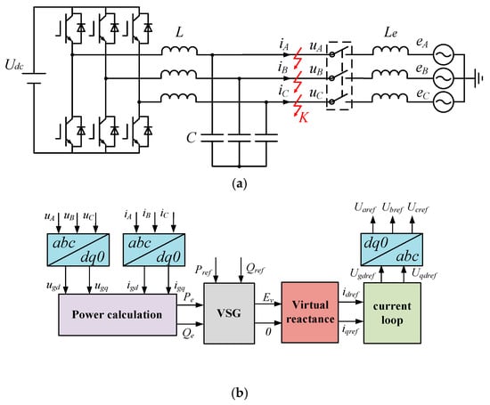
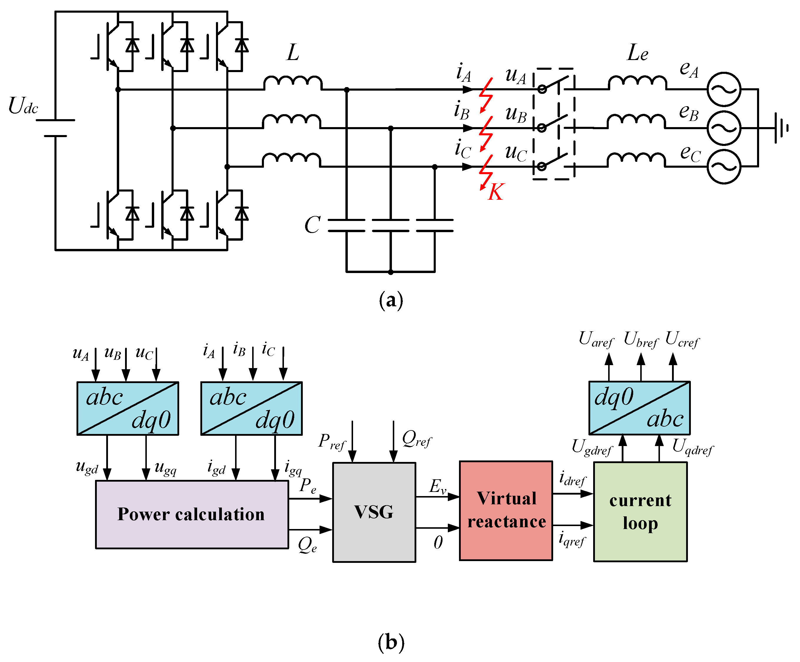
The topology of the grid-forming converter (GFM) grid-connected system is shown in Figure 1. Each bridge leg consists of two switching devices. The converter generates a two-level output voltage, which is connected to the grid through an LC filter. In Figure 1, uA, uB, uC, iA, iB, iC, denote the phase voltages and phase currents at the point of common coupling (PCC), respectively; L and C are the filter inductance and capacitance; eA, eB, eC are the grid phase voltages; Le is the line inductance; and Udc is the dc-side input voltage of the GFM converter. The three-phase PCC voltages uA, uB, uC and currents iA, iB, iC are transformed into the synchronous rotating reference frame to obtain the voltage components ugd, ugq and current components igd, igq, which are then fed into the power calculation module to derive the converter output active power Pe and reactive power Qe Based on the power feedback and the corresponding setpoints, the VSG control loop generates the virtual machine terminal voltage and phase angle, and further provides the current references idref and iqref. The inner current loop performs fast tracking regulation to produce the voltage control commands. Subsequently, a virtual-reactance loop is introduced, where an equivalent reactance voltage drop is superimposed on the voltage reference to enhance damping, improve adaptability to weak grids, and suppress fault-induced inrush currents. Finally, the modified Ugdref and Ugqref are transformed back to generate the three-phase reference voltages Uiref (i represent A phase, B phase, C phase), which are used for PWM modulation to drive the switching devices of the converter. The system parameters are listed in Appendix A.
Figure 1.
The grid-forming converter system: (a) Electrical Topology of the VSG Converter, (b) Control Structure of the VSG.
In Figure 1, abc denotes the three-phase stationary reference frame, and dq0 denotes the synchronous rotating dq0 reference frame.
3. Control Scheme with a Virtual-Reactance Loop
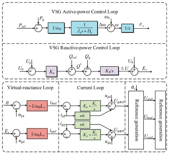
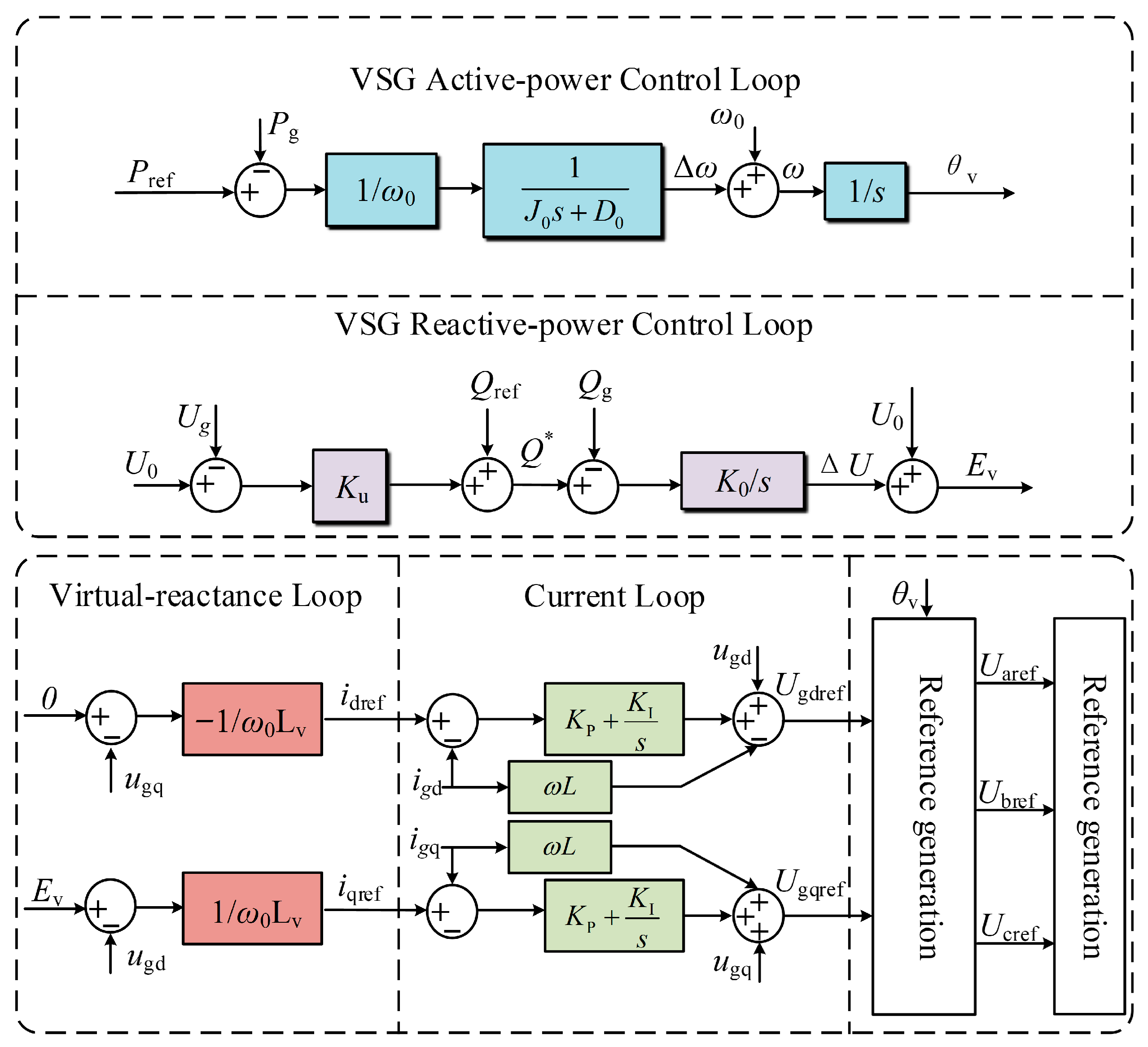
The VSG control consists of an active-power control loop, a reactive-power/voltage control loop, a virtual-reactance loop, and an inner current loop. Specifically, the active-power control loop generates the frequency deviation Δω based on the error between the active-power reference Pref and the measured active power Pg through the VSG dynamic block. The resulting Δω is added to the nominal angular frequency ω0 and then integrated to obtain the virtual voltage angle θv, thereby emulating the P–f characteristic and inertia support of a synchronous machine. The reactive-power control loop takes the deviation between the PCC voltage Ug and its reference as the input. Through the Q–U droop and reactive-power regulation, together with the reactive-power setpoint Qref, the reactive-power command Q* is obtained. By comparing Q* with the measured reactive power Qe, the voltage magnitude adjustment is produced and superimposed on the virtual electromotive force Ev, which realizes the Q–U droop behavior and voltage support. On this basis, the inner current loop employs the errors between the current references idref, iqref provided by the virtual-reactance loop and the measured currents igd, igq to generate the dq voltage references Ugdref, Ugqref via PI regulation, cross-coupling decoupling, and voltage feedforward. The resulting dq-axis voltage references are then transformed back to produce the three-phase modulation signals Uiref (i represent A phase, B phase, C phase), which are applied to the PWM modulator to drive the switching devices and generate the two-level output voltages.
As shown in Figure 2, the active-power control loop of the VSG can be expressed by Equation (1):
Figure 2.
Control scheme of the grid-forming converter.
In the above equation, J0 denotes the virtual inertia of the VSG, and D0 denotes the damping coefficient.
For the VSG with constant ac-voltage control, the active-power control loop can be expressed by Equation (2):
In the above equation, Ku denotes the voltage droop coefficient, and K0 denotes the integral gain.
The virtual-reactance control loop with internal electromotive-force droop can be expressed by Equation (3):
4. Current-Limiting Strategy Based on Adaptive Virtual Reactance
4.1. Fault Detection Criterion
Based on the control framework of the grid-forming converter, an adaptive virtual-reactance-based segmented current-limiting strategy driven by current measurements is proposed. During a fault, the proposed strategy adaptively adjusts the virtual reactance according to the severity of the output current exceeding its limit, thereby enabling coordinated soft current limiting in the moderate overcurrent region and hard current limiting in the severe overcurrent region. After fault clearance, a virtual-reactance recovery mechanism is employed to restore the converter to its steady-state operating point.
To implement the segmented current-limiting control, it is first necessary to establish a current-measurement-driven fault criterion and an overcurrent grading logic. In the synchronous rotating dq reference frame, the magnitude of the converter output current is defined as:
To distinguish different levels of overcurrent severity, the rated current is denoted by In, and the maximum allowable current is set to IM = 2In. A moderate-overcurrent threshold Ith1 = 1.5In is defined between them. Accordingly, the output-current grading logic is given as:
where SI = 0 indicates that the current does not exceed the limit, SI = 1 corresponds to the moderate overcurrent region, and SI = 2 indicates that the converter has entered the severe overcurrent region, in which a strong current-limiting action is required. After fault clearance, a recovery criterion is introduced to restore the virtual reactance to its steady-state base value. Let the current recovery threshold be Irec ≈ 1.05In [10,14]; then, the virtual-reactance recovery criterion is given as:
where Sc = 1 indicates that the post-fault condition has not yet recovered, whereas Sc = 0 indicates that the system has basically returned to a near-rated operating condition, and thus the virtual-reactance recovery process can be initiated.
4.2. Construction of the Current-Limiting Strategy
Under the VSG control scheme, a series virtual reactance is introduced to realize fault current limiting and damping enhancement. Its equivalent expression in the synchronous dq reference frame is given by:
where Xv(t) denotes the virtual resistance and virtual reactance. Under steady-state fault-free operation, the initial value of the virtual reactance is calculated from the rated grid voltage Un and the rated apparent power Sn of the converter according to Equation (8) [20].
(1). When SI = 1, the system operates under a voltage sag with moderate overcurrent. In this case, a drastic increase in the virtual reactance may compromise the closed-loop stability of the inner current loop. Therefore, while keeping the virtual resistance unchanged, the virtual reactance is increased to achieve a soft limitation on the current rising rate and peak value. The current exceedance is defined as:
When ΔI(t) ≤ 0, the current does not exceed the moderate overcurrent threshold and no additional current limiting is required. When ΔI(t) > 0, the increment of the virtual reactance is ΔXAVR(t) determined by the following nonlinear adaptive law:
where kx1 > 0 is the linear gain that determines the sensitivity of the virtual reactance to the current exceedance; kx2 > 0 and γ > 0 regulate the saturation level and variation rate of the exponential term, which smooths the virtual-reactance variation and avoids abrupt disturbances to the inner current loop.
The virtual reactance in the moderate overcurrent region is expressed as:
(2). When SI = 2, the system enters the severe overcurrent region, and the output current has exceeded the maximum allowable value IM. In this case, the virtual-reactance-based soft current limiting is insufficient to constrain the current within a safe range, and an adaptive equivalent virtual-reactance calculation based on the voltage vector is required so that the fault current magnitude can be hard-limited around IM. During the fault, the current-driving force through the virtual reactance is determined by the difference between the converter internal emf and the minimum value of the PCC three-phase voltage, denoted as Usamp. The required magnitude of the equivalent reactance should satisfy:
Since an adaptive virtual-reactance term ΔXAVR(t) has been introduced in the moderate overcurrent region, to ensure continuity between the severe and moderate overcurrent regions at the boundary Im→IM, the saturation value of the soft current-limiting component at the severe-overcurrent boundary is defined as:
Accordingly, the piecewise expression of the virtual reactance in the severe overcurrent region is given as:
In the above equation, ΔXREQ denotes the increment of the virtual reactance in the severe overcurrent region.
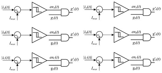
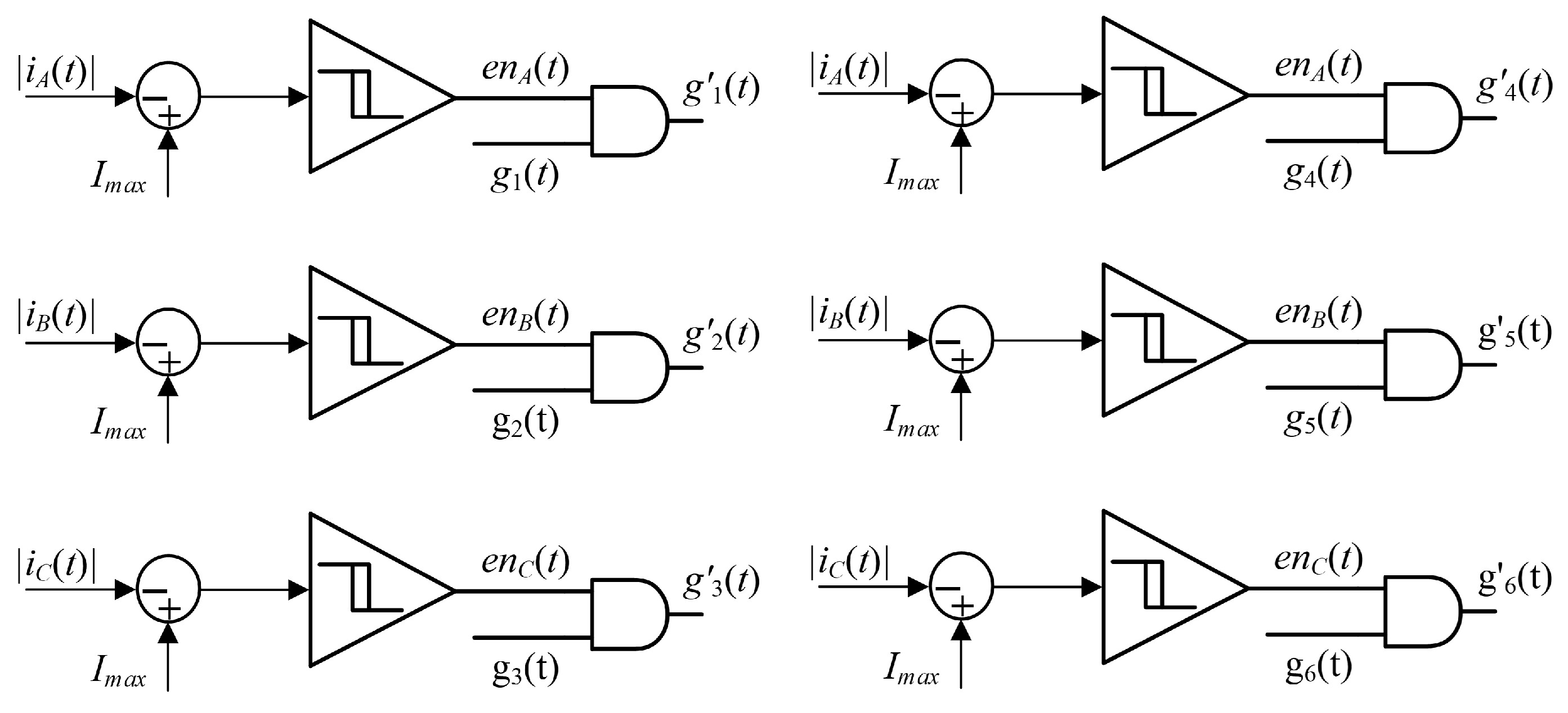
To suppress the instantaneous current spikes caused by control delays and modulation saturation in the severe overcurrent region, in addition to the hard current limiting achieved by calculating the equivalent virtual reactance according to Equations (12)–(14), a blocking logic based on the instantaneous phase-current magnitude is further incorporated into the IGBT gate signals. Specifically, the instantaneous currents of each phase are first compared with the allowable device peak threshold Imax = 1.2IM to produce the corresponding gate-enable signals ena, enb, and enc, as described in Equation (15). The enable signals are then logically ANDed with the original PWM gating pulses gk to obtain the final drive signals gk*, as given in Equation (16). When the rms value of any phase current exceeds Imax, the gating pulses of both the upper and lower switches in the corresponding phase leg are synchronously blocked, thereby coordinating with the virtual-reactance-based current limiting.
In the above equation, H denotes the step function: it takes the value of 1 when the quantity inside the parentheses is greater than or equal to 0, and 0 otherwise.
The blocking logic flowchart based on the instantaneous phase-current magnitude is shown in Figure 3:
Figure 3.
The blocking logic flowchart based on the instantaneous phase-current magnitude.
Overall, by combining the IGBT hardware gate-blocking logic with the adaptive regulation of virtual reactance, the proposed fault current-limiting method can theoretically not only effectively suppress overcurrent under different fault severities, but also further shorten the post-fault current recovery time through adaptive virtual-reactance adjustment according to the specific overcurrent level.
5. Experimental Validation
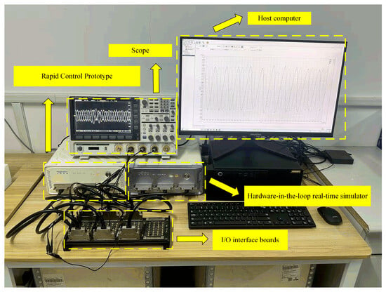
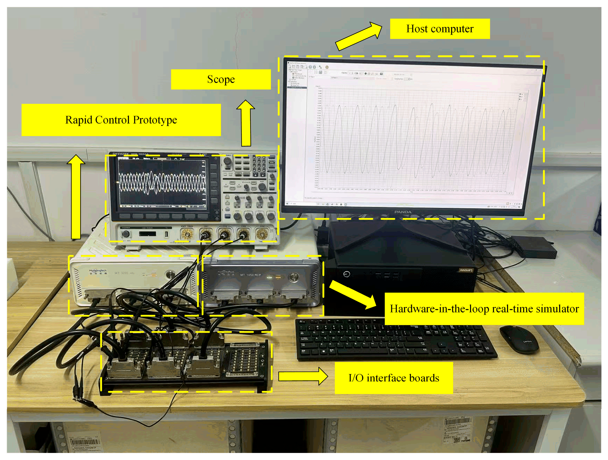
Based on the StarSim-RCP + StarSim-HIL experimental platform, according to Figure 4, an electromagnetic transient (EMT) simulation model of an EV charging converter (GFM) was established and the main parameters are listed in Table 1 to verify the effectiveness of the proposed virtual-reactance-based fault current-limiting method.
Figure 4.
Experimental platform based on StarSim-RCP and StarSim-HIL.
Table 1.
Parameters of the experimental model.
The experimental parameters are listed in Table 1. The converter is set to Pref = 15 kW and Qref = 0, and the rated phase current is IN = 20 A.
- (1)
- Verification of the Current-Limiting Strategy in the Moderate Overcurrent Region
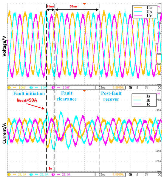
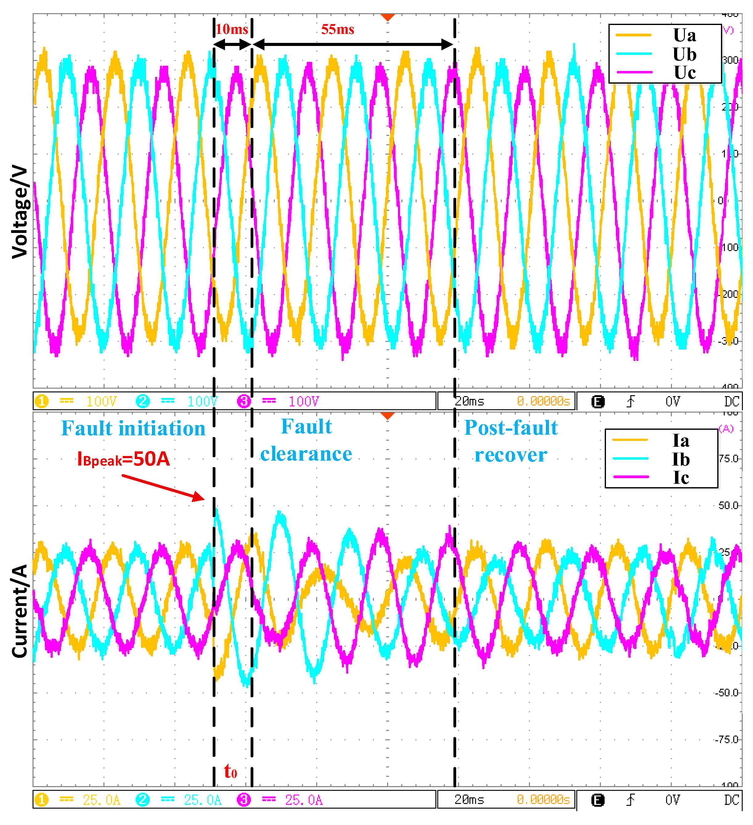
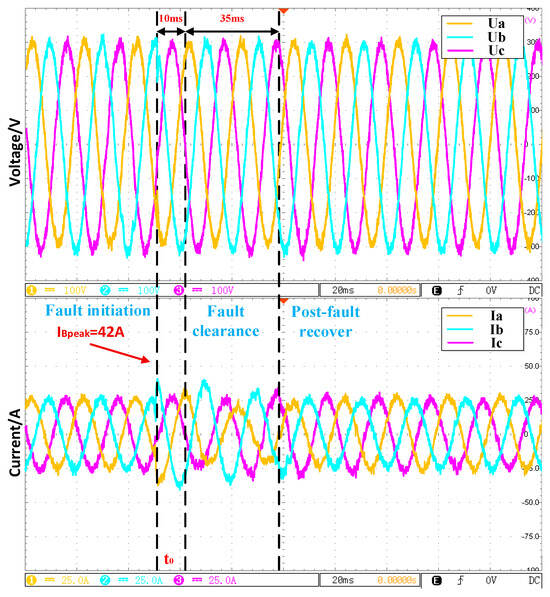
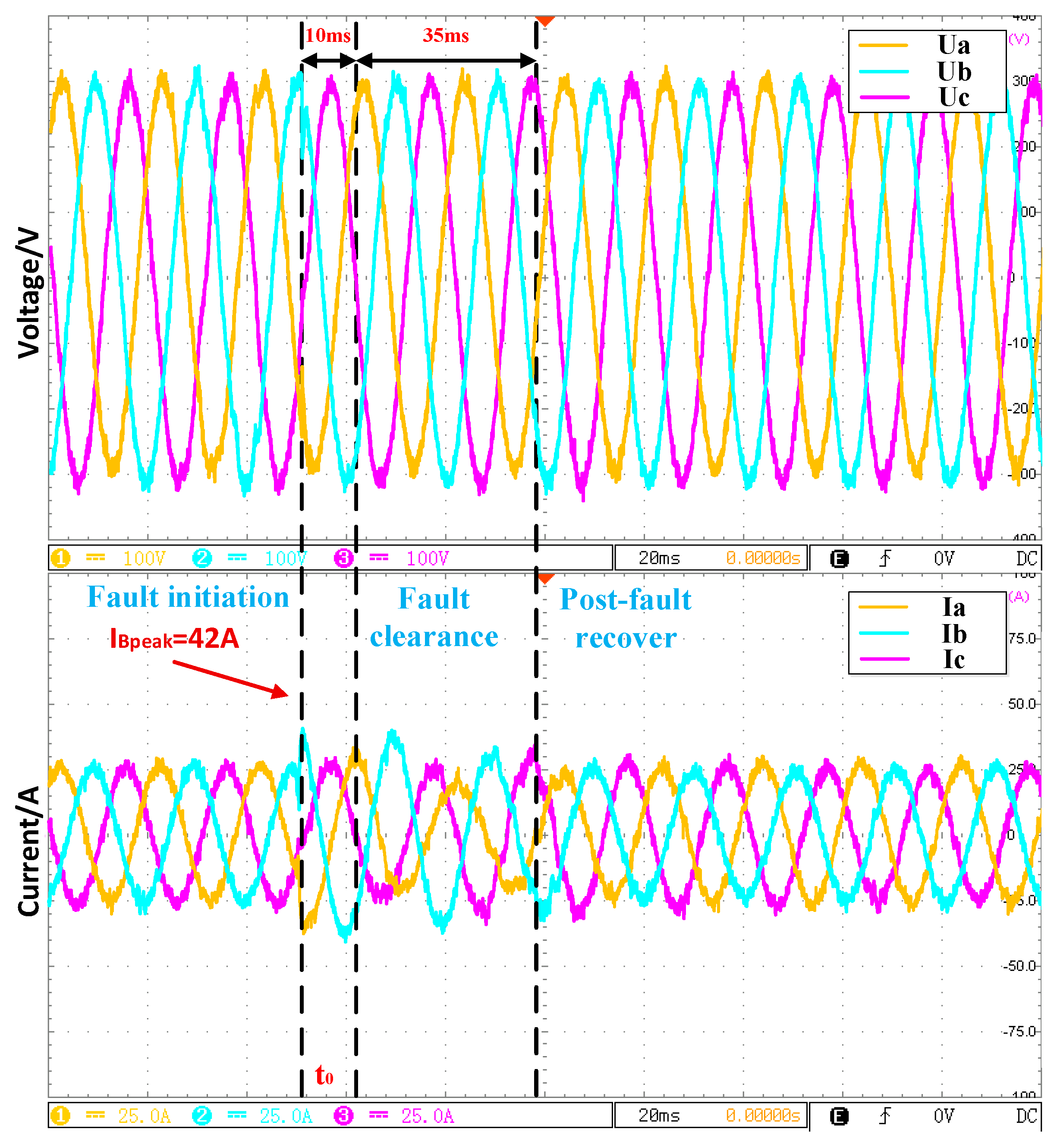
The location of the fault point K is shown in Figure 1. A three-phase grounding fault occurs at t0 with a fault transition resistance of 4 Ω, and it is cleared after 0.01 s. The fault duration is 10 ms. The simulated PCC voltage and current waveforms are shown in Figure 5 and Figure 6, respectively. Without the current-limiting strategy, the peak current of the most severely affected fault phase (phase B) reaches 50 A (blue curve), and the phase current returns to the rated value within 55 ms after fault clearance. With the proposed current-limiting strategy, the phase-current peak is reduced to 42 A, and the rms value is 29 A (below 1.5IN = 30 A); moreover, the phase current recovers to the rated value within 35 ms after fault clearance.
Figure 5.
PCC voltage and current waveforms under moderate overcurrent without current−limiting.
Figure 6.
PCC voltage and current waveforms under moderate overcurrent with current−limiting strategy.
- (2)
- Verification of the Current-Limiting Strategy in the Severe Overcurrent Region
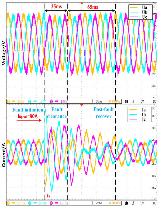
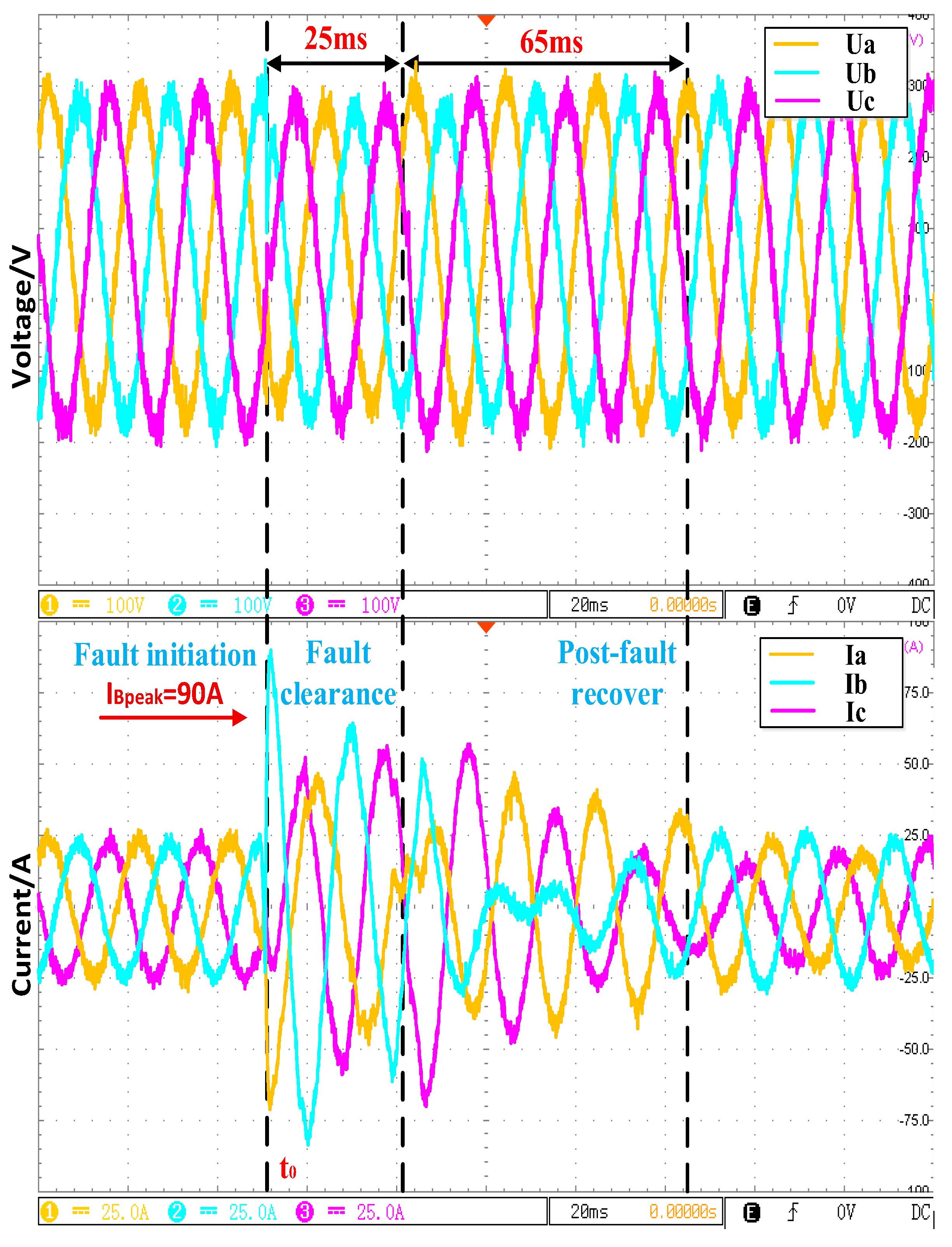
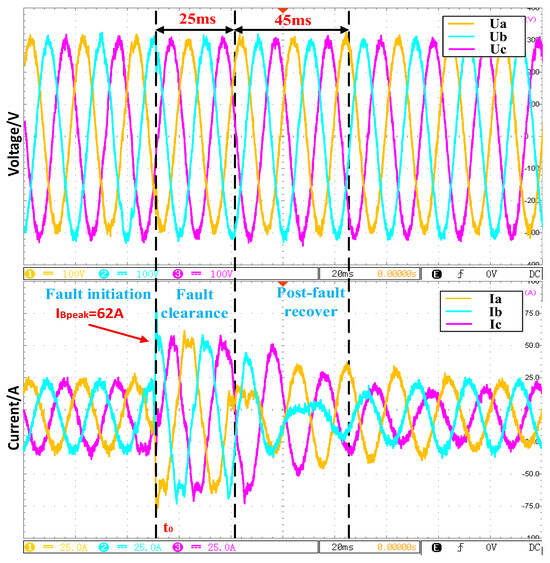
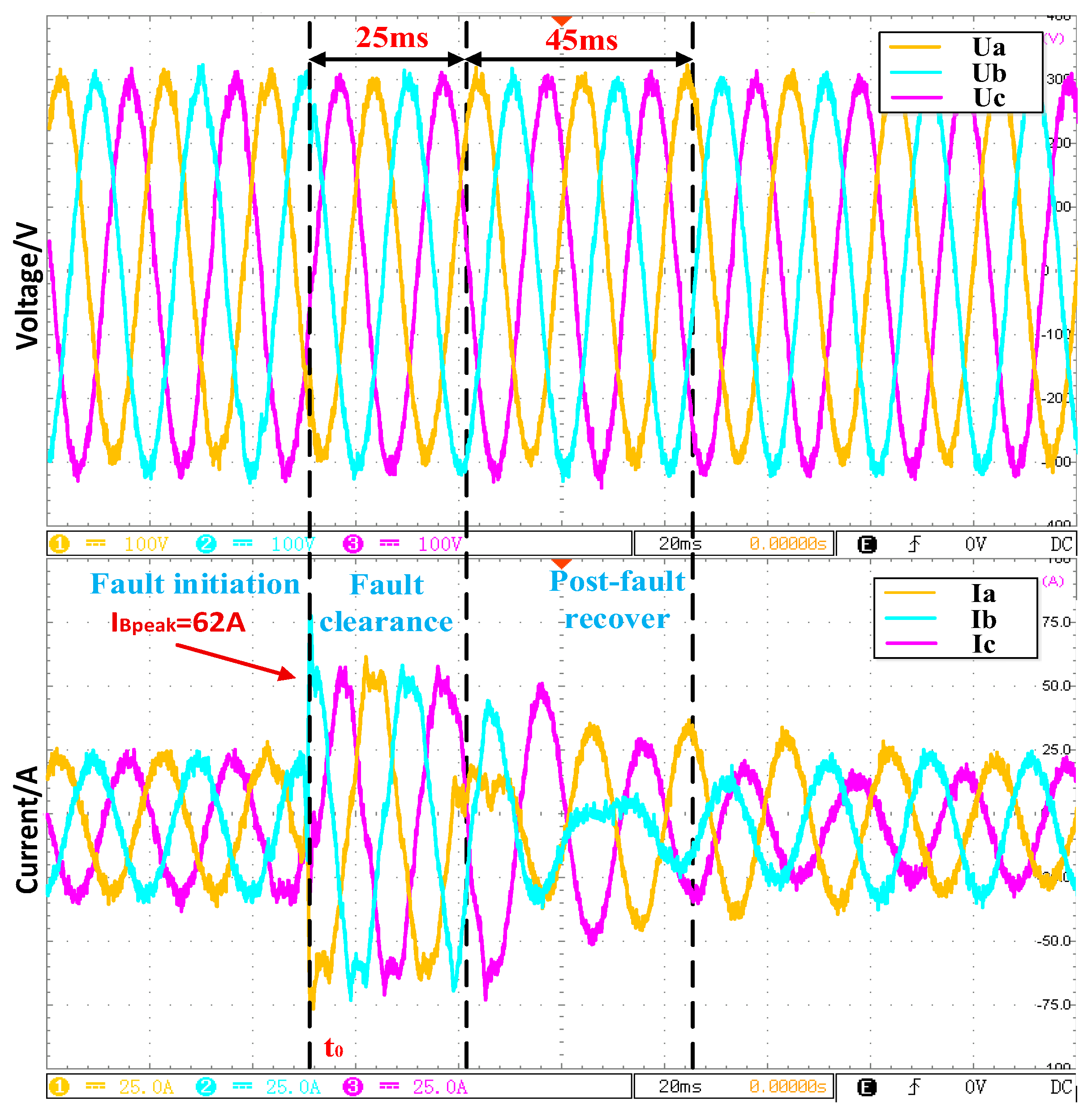
A three-phase grounding fault occurs at t0 with a fault transition resistance of 0.7Ω, and it is cleared after 0.025 s. The fault duration is 25 ms. The simulated PCC voltage and current waveforms are shown in Figure 7 and Figure 8, respectively. Without the current-limiting strategy, the peak current of the most severely affected fault phase (phase B) reaches 90 A (blue curve), and the phase current returns to the rated value within 65 ms after fault clearance. With the proposed current-limiting strategy, the phase-current peak is reduced to 62 A, and the rms value is 43 A, which is below 2.2IN = 44 A. Moreover, the phase current recovers to the rated value within 45 ms after fault clearance.
Figure 7.
PCC voltage and current waveforms under severe overcurrent without current−limiting strategy.
Figure 8.
PCC voltage and current waveforms under severe overcurrent with current−limiting strategy.
6. Conclusions
In this paper, for the moderate overcurrent region, a soft current-limiting action is achieved via adaptive virtual reactance, whereas for the severe overcurrent region, a hard current-limiting action is realized by further increasing the virtual reactance and blocking overcurrent bridge arm. The two current-limiting actions are unified into a piecewise virtual-reactance formulation, which ensures current limiting while shortening the post-fault restoration time. Experimental results demonstrate that, without significantly degrading the voltage-support capability, the proposed method effectively limits the fault-current peak, improves the dynamic performance of the inner current loop, and enhances the LVRT capability and operational reliability of grid-forming converters. In future research, the proposed method will be extended to asymmetric fault conditions, and its performance under very weak grid conditions with extremely low SCR will be further investigated.
Author Contributions
Conceptualization, H.L.; methodology, H.L.; software, H.L.; validation, Z.C.; formal analysis, Z.C.; investigation, H.L.; resources, H.L.; data curation, Z.C.; writing—original draft preparation, Z.C.; writing—review and editing, H.L.; visualization, Z.C.; supervision, H.L.; project administration, H.L.; funding acquisition, H.L. All authors have read and agreed to the published version of the manuscript.
Funding
This research received no external funding.
Data Availability Statement
Data are contained within no external the article.
Conflicts of Interest
The authors declare no conflicts of interest.
Appendix A
Table A1.
Variable definition.
References
- Yang, H.; Li, X.; Ge, J.; Huang, P.; Dong, Q. Planning V2G-capable EV Charging Stations in Urban Power-Transportation Networks. In Proceedings of the 2023 8th Asia Conference on Power and Electrical Engineering (ACPEE), Tianjin, China, 14–16 April 2023; pp. 1263–1267. [Google Scholar]
- Kavitha, D.; Preetha, A.; Nagavi, K. Harmonic Impact Assessment for EV Charging Stations Deployment in the Distribution System. In Proceedings of the 2023 International Conference on Energy, Materials and Communication Engineering (ICEMCE), Madurai, India, 14–15 December 2023; pp. 1–6. [Google Scholar]
- Liu, H.; Wang, Y.; Liu, Y.; Peng, Y.; Li, M.; Lei, W. The LVRT strategy for VSG based on the quantitatively designed virtual impedance. High Volt. Eng. 2022, 48, 245–256. [Google Scholar]
- Li, Z.; Chan, K.W.; Hu, J.; Or, S.W. An Adaptive Fault Ride-Through Scheme for Grid-Forming Inverters under Asymmetrical Grid Faults. IEEE Trans. Ind. Electron. 2021, 69, 12912–12923. [Google Scholar] [CrossRef] [Scilit]
- Zhou, Y.; Yao, W.; Zong, Q. Optimal Configuration of Grid-following/Grid-forming Switchable Units in New Energy Stations Based on Operating Short-circuit Ratio. Power Syst. Technol. 2024, 48, 1091–1104. [Google Scholar]
- Qiang, L.; Cao, Z.; Nie, X. Research on Dynamic Response Mechanism of Voltage Sag Based on Virtual Synchronous Machine. Electr. Eng. Eng. 2025, 21, 155–158. [Google Scholar] [CrossRef]
- Feng, X.; Huang, M.; Zhang, Z. Control Strategy for Improving VSG Frequency Stability in Energy Stroage Power Conversion System. High Volt. Appar. 2025, 61, 34–44. [Google Scholar]
- Qoria, T.; Gruson, F.; Colas, F.; Denis, G. Critical clearing time determination and enhancement of grid-forming converters embedding virtual impedance as current limitation algorithm. IEEE J. Emerg. Sel. Top. Power Electron. 2019, 8, 1050–1061. [Google Scholar] [CrossRef] [Scilit]
- Fan, B.; Liu, T.; Zhao, F.; Wu, H.; Wang, X. A review of current-limiting control of grid-forming inverters under symmetrical disturbances. IEEE Open J. Power Electron. 2022, 3, 955–969. [Google Scholar] [CrossRef] [Scilit]
- Sadeghkhani, I.; Golshan, M.E.H.; Guerrero, J.M.; Mehrizi-Sani, A. A Current Limiting Strategy to Improve Fault Ride-Through of Inverter Interfaced Autonomous Microgrids. IEEE Trans. Smart Grid 2017, 8, 2138–2148. [Google Scholar] [CrossRef] [Scilit]
- Roopashree, D.V.; Venugopal, N. A Low-Voltage Ride-Through strategy using fuzzy based controller for 3phase grid connected PV system. In Proceedings of the 2021 International Conference on Recent Trends on Electronics, Information, Communication & Technology (RTEICT), Bangalore, India, 27–28 August 2021; pp. 34–37. [Google Scholar]
- Anirudh, K.; Bahirat, H.J.; Chatterjee, K. Current-Limiting-Type Fault Ride-Through Control Scheme for Converters in DC Microgrid. IEEE J. Emerg. Sel. Top. Power Electron. 2024, 12, 1523–1534. [Google Scholar] [CrossRef] [Scilit]
- Du, W.; Mohiuddin, S.M. A Two-Stage Current Limiting Control Strategy for Improved Low-Voltage Ride-Through Capability of Direct-Droop-Controlled, Grid-Forming Inverters. In Proceedings of the 2023 IEEE Energy Conversion Congress and Exposition (ECCE), Nashville, TN, USA, 29 October–2 November 2023; pp. 2886–2890. [Google Scholar]
- Wang, F.; Xu, J. Adaptive current limiting strategy based on grid-forming and energy-storage SVG. Power Syst. Prot. Control 2024, 52, 54–64. [Google Scholar]
- Cui, T.; Liang, J.; Liu, S.; Dong, J.; Li, X.; Li, A. Research on PV Low Voltage Ride-Through Control Based on RT-LAB Hardware-in-the-Loop. In Proceedings of the 2022 China International Conference on Electricity Distribution (CICED), Changsha, China, 7–8 September 2022; pp. 1299–1304. [Google Scholar]
- Li, H.; Gao, Z.; Ji, S.; Ma, Y.; Wang, F. An Inrush Current Limit Method for SiC-based Multi-level Grid-connected Converter During Low-Voltage Ride-Through. In Proceedings of the 2021 IEEE Applied Power Electronics Conference and Exposition (APEC), Phoenix, AZ, USA, 14–17 June 2021; pp. 2044–2049. [Google Scholar]
- Qiao, X.; Chen, L.; Tang, J.; Ding, M.; Zhao, Z. Study on an Advanced Low Voltage Ride-Through Control Strategy of Energy Router. In Proceedings of the 2021 IEEE 4th International Conference on Computing, Power and Communication Technologies (GUCON), Kuala Lumpur, Malaysia, 24–26 September 2021; pp. 1–6. [Google Scholar]
- He, J.; Sangwongwanich, A.; Yang, Y.; Quan, Z.; Li, Y.R.; Iannuzzo, F. Discontinuous Modulation for Improved Thermal Balance of Three-Level 1500-V Photovoltaic Inverters under Low-Voltage Ride-Through. In Proceedings of the 2021 IEEE Energy Conversion Congress and Exposition (ECCE), Vancouver, BC, Canada, 10–14 October 2021; pp. 103–108. [Google Scholar]
- Kumar, U.; Choudhary, N.K.; Kundu, P. Relay Coordination in Networked Microgrids with Low Voltage Ride-Through Capabilities of Distributed Generators. In Proceedings of the 2025 IEEE 5th International Conference on Sustainable Energy and Future Electric Transportation (SEFET), Jaipur, India, 9–12 July 2025; pp. 1–6. [Google Scholar]
- Rodriguez, P.; Candela, I.; Citro, C.; Rocabert, J.; Luna, A. Control of grid-connected power converters based on a virtual admittance control loop. In Proceedings of the 2013 15th European Conference on Power Electronics and Applications (EPE), Lille, France, 35 September 2013; pp. 1–10. [Google Scholar]

Disclaimer/Publisher’s Note: The statements, opinions and data contained in all publications are solely those of the individual author(s) and contributor(s) and not of MDPI and/or the editor(s). MDPI and/or the editor(s) disclaim responsibility for any injury to people or property resulting from any ideas, methods, instructions or products referred to in the content. |
© 2026 by the authors. Licensee MDPI, Basel, Switzerland. This article is an open access article distributed under the terms and conditions of the Creative Commons Attribution (CC BY) license.