


Abstract
The article presents the results of research on the justification of the working unit parameters and the structural scheme of the chisel for loosening stubble fields. It was established that, according to the criterion of minimum draft resistance, the optimal installation angles are 20–24 degrees to the bottom of the furrow at a working share width of 40–50 mm. The calculated values of the share installation angles were verified on a laboratory setup, and the results confirmed the theoretical calculations. Based on the quality of loosening of the worked layer and the preservation of stubble, the shank width should be 20–30 mm, the share width 40–50 mm, and the share installation angle 20–24 degrees. The shank should be equipped with a safety mechanism to prevent breaking or bending. The results of research on different leveling device options are presented, and the structural–technological scheme, main parameters, and operating modes of the tool for chiseling compacted stubble fields are substantiated. Dependencies of the treatment quality on the parameters of the loosening working units, the leveling device, and the operating speed of the implement were obtained. Based on the justified parameters, an experimental prototype of the soil chiseling machine was manufactured and field tests were conducted under production conditions on stubble fields.
1. Introduction
The soil surface of the main grain-growing regions of northern Kazakhstan is characterized by great diversity, but in terms of texture, the most widespread soils are heavy loams (50.7%) and medium loams (21.2%). These soils contain 45 to 80% of physical clay and therefore they tend toward self-compaction under the influence of natural factors and human activity. The majority of agricultural soils (more than 80%) contain no more than 2–4% of humus in the arable layer. The flat relief of the area and the significant number of windy days (more than 70% of the year), when wind speed exceeds 5 m/s, contribute to the development of wind erosion of the soil.
These soils poorly absorb atmospheric precipitation, tend toward self-compaction and form a cloddy structure. During the summer period, precipitation quickly infiltrates the thin surface layer without penetrating the soil layer where the majority of plant root systems are located. The surface layer dries out rapidly under the influence of the wind and the sun, which contributes to the occurrence of aerial and soil drought during the initial stage of vegetation. Winter precipitation, after snowmelt, does not infiltrate the arable layer due to its over-compaction and the formation of a cloddy structure; instead, it flows off and accumulates in depressions, forming limans and lakes.
All these factors indicate the necessity of performing mechanical treatments at different depths for stubble and fallow fields. Almost the entire territory of northern Kazakhstan is located in a zone of active wind activity. Therefore, for the treatment of stubble and fallow fields, it is recommended to use implements that allow maximum preservation of stubble and crop residues and create a mulching, wind-resistant field surface.
Similar problems in crop cultivation are occurring in Argentina, China, Iran, and Canada [1,2,3,4,5,6,7]. This is also due to soil compaction and insufficient moisture for plant growth in the root zone, which affects the efficiency of crop cultivation.
Soil chiseling is used for strip treatment of stubble and row-crop fields and is intended to restore the water and air balance in the lower soil layers. Soil chiseling is a strip treatment in which strips with stubble and chopped plant residues remain between adjacent passes of the working units. This alternating sequence of treated strips and stubble with mulch contributes not only to moisture accumulation but also to its preservation until the beginning of sowing [8,9,10,11,12,13,14,15,16]. The effectiveness of soil chiseling has been proven by numerous studies [17,18,19,20,21].
The initial requirements for the soil chiseling operation recommend selecting a working depth within the range of 25–40 cm. The distance between the chisels can vary from 70 to 300 cm depending on the conditions, while the deviation from the specified working depth should not exceed ±1.5 cm (2 cm). The width of the loosened strip should not exceed 50 cm, and the width of the chisel slit should not exceed 5 cm. The ridge height along the edges of the slits at a working depth of 30 cm should not exceed 8 cm, and at a depth of 40 cm it should be no more than 10 cm, with stubble preservation of at least of 80%. These indicators can be achieved when the soil hardness does not exceed 3.5 MPa and the moisture content is 18–26% [22].
Modern chiselers lead to an increase in the loosening zone, the width of the slit, and the displacement of large soil fractions onto untreated strips when they perform soil chiseling on over-compacted soils with a working layer moisture of 8–15% and hardness of 4–6 MPa at speeds above 7 km/h, using a structural–technological scheme consisting of a disk knife, chisel, and packing roller. This operation causes the loss of soil moisture, the incorporation of stubble and chopped plant residues into the soil, and changes in the structure of the surface layer. The increased displacement of soil fractions and incorporation of residues create the necessity for an additional technological operation during the spring period, aimed at breaking up large soil aggregates and filling the slits to restore optimal soil conditions.
Practice shows that soils in the Republic of Kazakhstan are heterogeneous in their physical and mechanical properties. During dry periods, soil hardness on certain sites can reach 10–12 MPa, and in some regions of the republic, bedrock (stony soils) can also occur. These features significantly affect the reliability of the design of the working units of chiselers. When a working unit encounters over-compacted soil or stones, the share or the disk knife bends or detaches in the best case and in the worst case, the shank of the chisel or the disk knife breaks.
The results of research aimed at developing working tools and machines for deep soil cultivation, their effectiveness depends on the soil conditions in which the equipment being developed will be used. Research shows that for different soil conditions the shape, parameters of the working parts and the technological scheme of the machine will have certain differences [23,24,25].
Foreign manufacturers of chiselers, such as “Case”, “Unverferth”, “John Deere”, “Wil-Rich 357” (USA), “Salford” (Canada), and others, have developed chiselers with mechanisms for controlling the load on the working units. The designs of these chiselers use shear bolts, springs and hydraulic load compensators. These technical innovations ensure the preservation of the working units. However, the main disadvantages of machines from overseas are their high initial purchase cost, the significant expenses for spare parts required during operation, and the low quality of work performance on over-compacted soils.
The solution to this problem is the improvement of the parameters of the working units and the structural–technological scheme of the chiselers. The innovation in the development of a tool for slitting compacted and stony soils is that the technological scheme of the tool, the parameters of the tool and the working bodies were justified for the dry and compacted soils of the northern region of Kazakhstan and adapted to them. New dependencies were obtained for the influence of the physical and mechanical properties of soil, parameters of working bodies for slitting and speed of movement on agrotechnical and energy indicators.
The justification of the type, parameters and operating modes of the working units with leveling devices for a tool for chiseling compacted soils, as well as the selection of a safety mechanism, is the aim of this work.
2. Materials and Methods
The stability of the soil chiseling process for over-compacted and stony fields can be ensured at the specified quality of work and minimal possible energy costs when the parameters of the working units are optimized. The parameters of the working units include the width and installation angle of the share, as well as the width and thickness of the shank.
It is known that working units used in soil-tillage implements differ in the variety of working surface shapes. By using the method of transitioning from complex to simple surfaces through their division into a series of infinitesimal flat elements, they can be reduced to elementary working surfaces in the form of a wedge. Existing models of the interaction between a double-edged wedge and the soil, as a rule, assume the homogeneity of the physical and mechanical properties of the treated layer with depth, the independence of the ultimate stresses of soil sample failure from the load application scheme, and the ability of the soil layer to move along the surface of the working unit throughout the entire working depth [9,14,17,18].
The real soil layer has a clearly differentiated horizontal profile structure. This is especially evident under modern conditions, when the transition to minimum and zero tillage technologies for cereal crops has reduced the number of deep mechanical treatments. Considering that in recent years’ significant compaction has occurred in medium and heavy soils below the seed placement depth, and that new working units and implements are being developed to loosen this layer, it became necessary to identify the patterns of interaction between a double-edged wedge and soil differentiated into two layers along the profile. Taking into account the characteristics of the treated layer profile and using the failure patterns of each layer, computational schemes were developed and the regularities of the variation in force characteristics depending on the wedge parameters, the physical and mechanical properties of the soil layers, and the operating speed were obtained.
The methods accepted in agricultural and theoretical mechanics, as well as in the theory of material resistance to failure were used in theoretical studies. The movement of double-edged wedges in a soil layer differentiated into two layers with different physical and mechanical properties, and the forces acting on the wedge at all stages of its movement in the treated layer, taking into account the dynamic component of resistance, were considered. The assumption was made that the displacement of the wedge from its initial position to the final point ensures the failure of the displaced soil layer. The projections of the soil resistance forces during the wedge movement onto the coordinate axes were taken as draft resistance along the horizontal axis and penetrating forces along the vertical axis. The draft resistance of the working unit is the sum of the draft resistance of the share, as a double-edged wedge, and the draft resistance of the shank.
The draft resistance and the quality of the technological process served as the evaluation criteria for the working unit parameters in the experimental studies.
The available literature sources and the technical characteristics of existing soil chiseling implements were studied to collect information on leveling devices [22,26,27,28].
The obtained scientific and technical information on leveling devices was processed using standard methods of comparison, analysis, and synthesis.
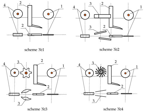
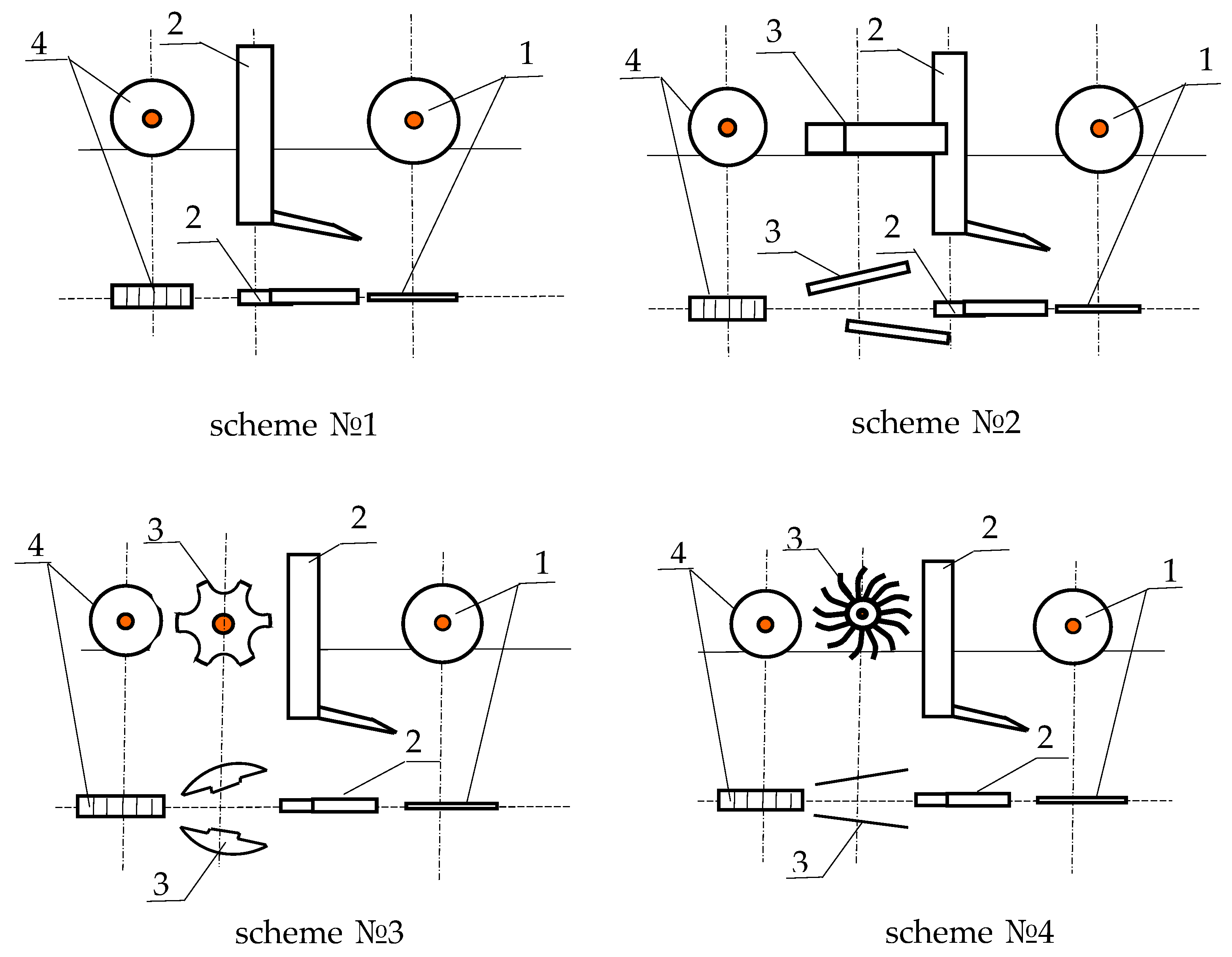
Several design and technological schemes of the soil chiseler were examined when justifying its structural–technological configuration, and these schemes are shown in Figure 1. The structural–technological schemes assume the sequential arrangement on the implement frame of the following working units: a cutting disk (1), followed by the installation of a chisel (2), behind which the soil turners (3) (plates, BDT disks, and BIG needle working units) are installed to fill the slit with soil fractions, and a packing roller (4) is intended to fill the slit with soil, crush large soil fractions, and level the treated field surface.
Figure 1.
Structural–technological schemes: 1—cutting disk; 2—chisel; 3—soil turners; 4—packing roller.
Structural–technological scheme №. 1 includes a cutting disk (1), a chisel (2), and a locally acting rod packing roller (4). Scheme №. 2 includes a cutting disk (1), a chisel (2), and soil turners (3) in the form of two plates arranged at an angle of 25° to the direction of movement, and a locally acting rod packing roller (4). Scheme №. 3 includes a cutting disk (1), a chisel (2), and soil turners (3) in the form of two BDT disks arranged at an angle of 25° to the direction of movement, and a locally acting rod packing roller (4). Scheme №. 4 includes a cutting disk (1), a chisel (2), and soil turners (3) in the form of two BIG needle working units arranged at an angle of 25° to the direction of movement, and a locally acting rod packing roller (4).
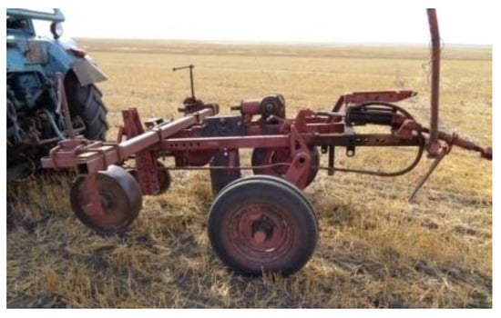
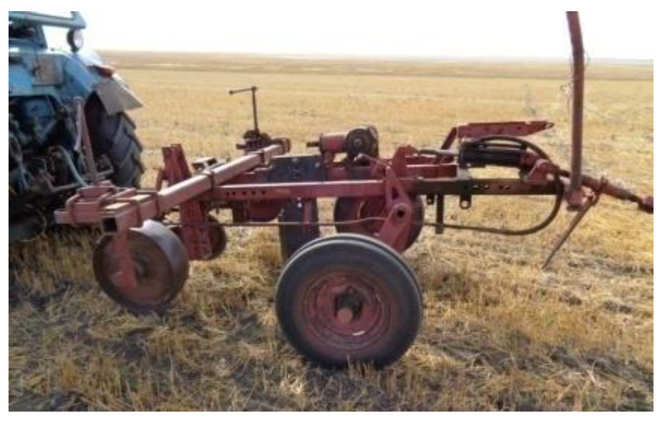
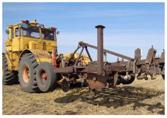
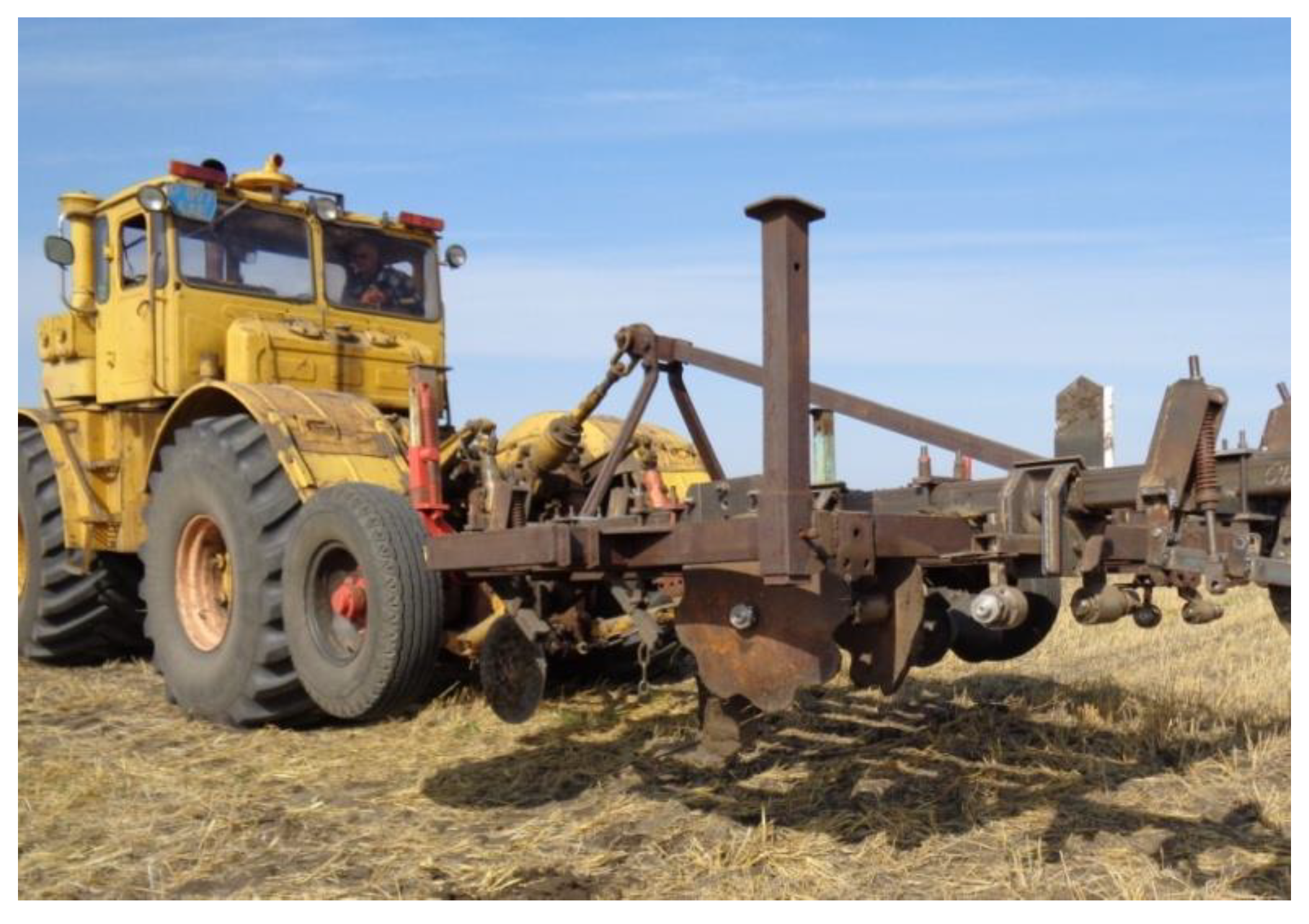
Two laboratory-field units (LFU) were manufactured for conducting field studies based on the analysis of designs. One LFU justified the parameters of the working unit for soil chiseling (Figure 2), and the other LFU justified the structural–technological scheme of the implement (Figure 3).
Figure 2.
Laboratory-field unit for justifying the parameters of the working unit.
Figure 3.
Laboratory-field unit for justifying the structural–technological scheme of the implement.
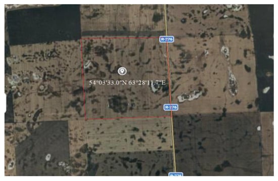
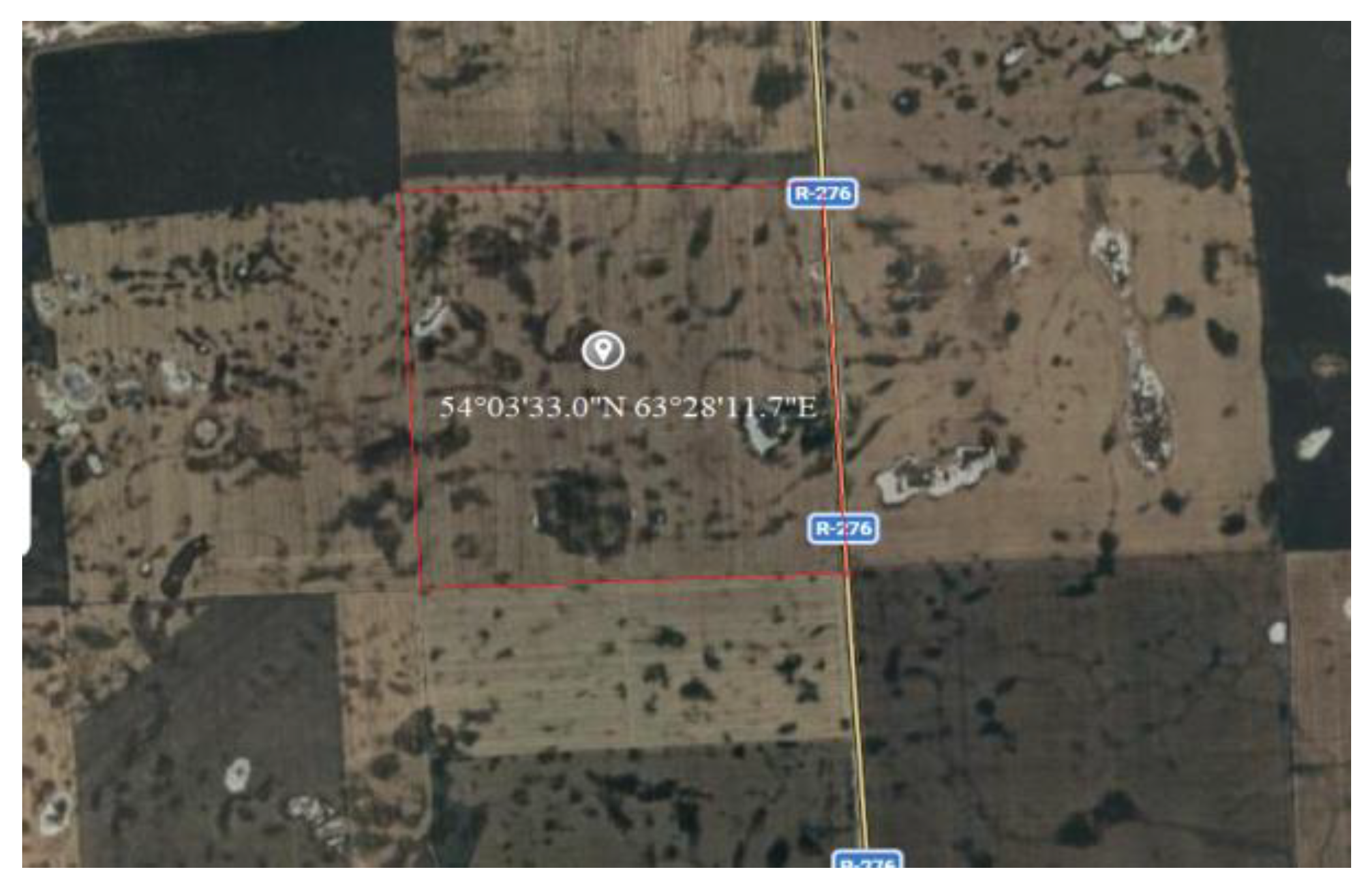
The tests were conducted during autumn cultivation of stubble fields at Zhanakhay LLC in the Fyodorovsky District of Kostanay Oblast, Kazakhstan. A map showing the location is shown in Figure 4. The exact coordinates are 54°03′33.0″ N latitude and 63°28′11.7″ E longitude.
Figure 4.
Map showing the location of the tests.
Working units and variants of leveling devices were manufactured, and laboratory–field tests were conducted, which refined the parameters of the working units and justified the structural–technological scheme of the implement for chiseling compacted soils.
The values of moisture, density and hardness of the treated soil layer were determined to characterize the soil layer during the experimental studies. The determination methodology followed the requirements of GOST 20915 [29].
The agrotechnical evaluation of the variants of working units and the structural–technological scheme of the machine was carried out in accordance with the requirements of ST RK 1560 [30] and GOST 33736 [31].
Two variants of chisel shanks with thicknesses of 20 mm and 30 mm were manufactured for conducting the studies. The shank design provides the possibility to change the cutting angle (the installation of the share relative to the horizontal surface) within the range of 10° to 40° with a step of 10°. The studies were conducted as follows: a 40 mm wide share was installed on the 20 mm thick shank at a cutting angle of 10°. Then, the working unit with these characteristics was pulled through the soil at a depth of 30 cm, at speeds from 5.4 to 10.8 km/h with a step of 1.8 km/h. A disk knife was installed in front of the shank. After a series of experiments, the next cutting angle was set, and the experiments were repeated. After completing the studies for all the angles and schemes provided by the experimental plan, a share of the next width was installed on the shank, and the experiments continued. Upon completion of the series of experiments with the 20 mm shank, a 30 mm thick shank was installed, and the experiments were repeated. During the field experiments, the angles of soil layer shearing were determined and samples were collected for subsequent determination of the friction coefficients of soil layers against metal and soil against soil.
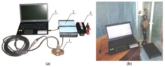
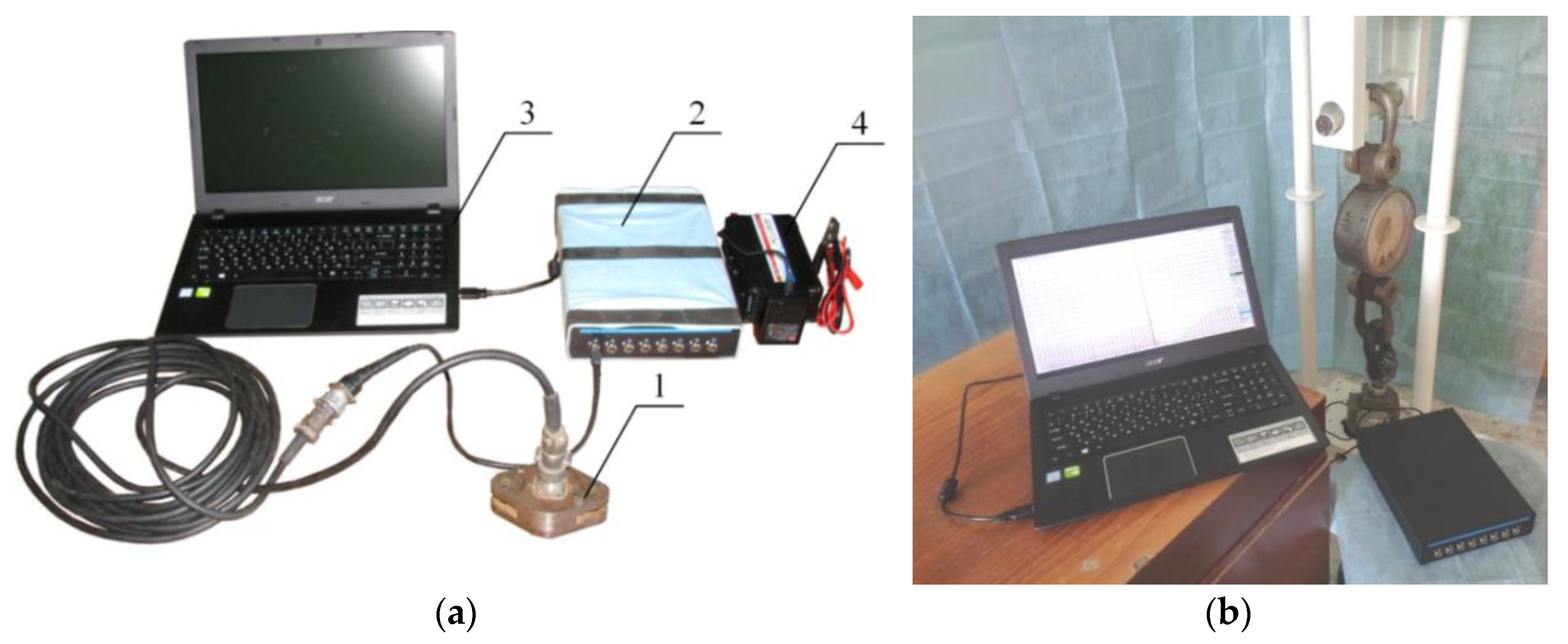
The draft force was measured using strain-gauge equipment, which included a strain-gauge link with a measurement range up to 3t, a ZET017-T8 strain-gauge station (manufacturer ZETLAB, Moscow, Russia), a portable Acer Aspire E 15 personal computer (manufacturer Acer, Chongqing, China), and a 12–220 V voltage converter Robiton R300 (manufacturer Robiton, Moscow, Russia), as shown in Figure 5.
Figure 5.
General view of strain-gauge equipment: (a)—strain-gauge equipment; (b)—calibration stand for strain-gauge links; 1—strain-gauge link; 2—strain-gauge station; 3—portable PC; 4—12–220 V voltage converter.
The strain-gauge equipment was calibrated on a special stand before conducting the tests. The calibration used the stepwise loading method from 0 to 30 kN and back with a step of 2 kN through a general-purpose spring-type tension dynamometer DPU-50 of the second accuracy class.
The system recorded the load values on the dynamometer and the corresponding readings of the strain-gauge link, processed by the ZET017-T8 strain-gauge station and displayed on the screen of the portable PC during the calibration tests. The test repetition was fourfold. The calibration tests showed that the measurement error remained within 0.39–1.96% at all stages of load variation. This method proved reliable during previous studies [32,33].
The method determined the motion speed and draft force in accordance with the requirements of GOST R 52777 [34].
The obtained test data were processed using the method of mathematical statistics [35,36,37]. During the processing, the system calculated the statistical characteristics of the sample for quantitative variability of the trait, determining the mean value, standard deviation and coefficient of variation. The system performed approximation of dependencies and determined the trend line. The system constructed graphical dependencies and carried out calculations using the Excel software.
3. Findings
3.1. Theoretical Determination of the Chisel Draft Force Based on the Shank Thickness, Share Width and Share Angle
Existing models of the interaction of two- and three-edged wedges with soil generally assume the homogeneity of the physical and mechanical properties of the tilled layer along its depth, the independence of the ultimate stresses of soil sample failure from the load application scheme and the ability of the soil layer to move along the surface of the working tool throughout the entire depth of tillage [38,39,40,41,42].
The real compacted soil layer has a profile structure clearly differentiated along the horizons. The medium and heavy soils have experienced significant compaction of the soil layer located below the seed placement depth in recent years, and new working tools and implements have been developed to loosen this layer. This situation created a need to identify the patterns of interaction of the two-edged wedge with soil differentiated into two layers along the profile.
The stability of performing the soil chiseling process on stubble fields at a given work quality and minimal energy expenditure can be ensured with optimal parameters of the working tools. The parameters of the working tools include the shank thickness of the chisel, the width of the share, and the share angle.
The draft force of the chisel (PT) depends on the inclination angle and the shank thickness of the chisel, as well as on the width and the angle of the share. It consists of the draft force of the chisel shank and the draft force of the share.
where —traction resistance of the slitter, N;
—chisel shank resistance, N;
—share resistance, N.
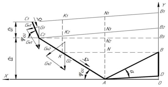
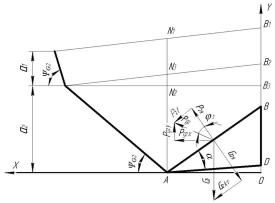
The main component of the draft force of the share is the soil resistance to deformation. Therefore, we consider the interaction of the two-edged wedge with the tilled layer, which has two distinct soil horizons. We assume that the two-edged wedge has a sharp cutting edge with a blade thickness of less than one millimeter and no back bevel, and that the movement of the wedge from the initial to the final position is sufficient to break the tilled layer along the line AC2C1 (Figure 6).
Figure 6.
The scheme of the decomposition of forces acting on the wedge due to the weight of the soil layer.
From the soil side, a support force acts on the wedge, the magnitude of which is determined by the potential soil shear resistance forces and the inertial force of the soil layer.
A support force from the soil acts on the wedge, and its magnitude is determined by the potential soil shear resistance forces and by the inertial force of the soil layer :
where —soil pressure force on a wedge, N;
—potential shear strength of soil, N;
—force of inertia of the formation, N.
The potential shear force is equal in magnitude to the force required to displace the soil element AC2C1K and to deform it with its working face AB. The shear of the second layer occurs along the surface AC2, which is inclined to the bottom of the furrow at an angle ψG2, as determined by Formula (3):
where —inclination angle of the shear plane of the second layer, degree;
—friction angle of the second layer against the metal, degree;
—soil-on-soil friction angle, degree.
The shear of the first (surface) layer occurs along the surface C2C1, which is inclined to the bottom of the furrow at an angle (Figure 6), the magnitude of which is determined by Formula (4):
where —inclination angle of the shear plane of the first layer, degree;
—friction angle of the first layer against the metal, degree;
—first layer soil-on-soil friction angle, degree.
Since the surface layer does not have contact with the working surface of the wedge, the angle φ1 is equal to zero.
The soil of the second layer exerts a shear resistance that generates a normal force on the working surface of the wedge AB. During the movement of the second layer along the plane AB, a friction force arises from the normal force , which is equal to:
where —friction force on the surface of the wedge AB, N;
—force of normal pressure on the surface of the wedge AB, N.
The soil of the first layer exerts a shear resistance that generates a normal force on the working surface of the wedge AB. Since the surface layer does not have contact with the working face AB during ashear, the additional friction force from the normal force is equal to:
where —friction force from normal force , N;
—the force of normal pressure of the first layer on the working surface of the wedge AB, N.
The resultant force P12 from the action of the normal forces and , and the frictional forces and caused by these normal forces, is equal to:
where —resultant of forces from the action of normal forces and frictional forces, N.
The normal stress in the shear plane AC2C1 is generated by the force P12 and by the normal component of the weight of the soil layer G2 on the shear plane AC2, and is determined by the expression:
where —gravity force of the formation on the shear plane AC2, N;
, —density of the first and second soil layers, g/sm3;
, —working depth of the first and second layer, sm.
The weight of the soil layer G1 acts on the shear plane C2C1 and can be determined by the equation:
where —gravity force of the formation on the shear plane C2C1, N;
b—wedge width, sm;
q—gravitational acceleration, m/s2.
Shear resistance forces S2 and S1 act on the rupture surfaces AC2 and C2C1, respectively, and these forces are equal to:
where —soil shear resistance force on a plane C2C1, N;
—soil shear resistance force on a plane AC2, N;
,—area of the shear surface of the second and first layers;
—shear stresses acting on the second and first soil layers.
The shear stresses are determined by the cohesion forces and the normal stress on the failure plane according to Coulomb’s law.
The normal stresses on the shear plane AC2 (σ2) are generated by the projections of the forces P2 and G2, and on the plane C2C1 by the projections of the forces P2 and G1.
The following equality is satisfied on both shear planes:
where , —projection of the force P2 on the corresponding shear plane.
We substitute the values of the components of this equation and project the forces and onto the x-axis, and we obtain:
where —adhesion force in the shear plane, N.
- -
- For the second layer
—projection of the destruction force of the first layer onto the X-axis, N.
- -
- For the first layer
The projection of the support force from the dynamic pressure of the soil layer on the x-axis is equal to:
where —projection of the dynamic pressure force of the soil layer onto the X-axis, N;
—wedge speed, km/h.
The projections of the support force from the soil on the wedge are equal to:
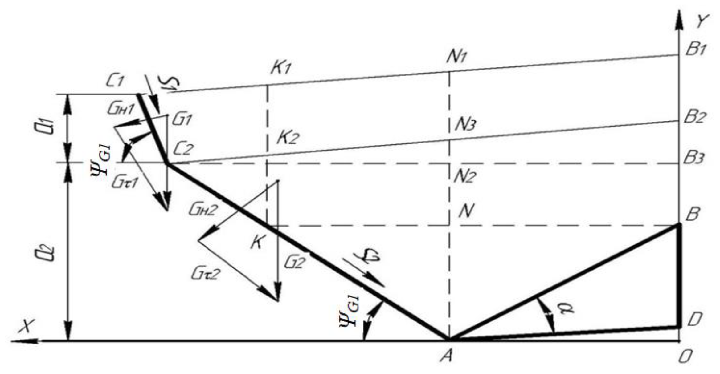
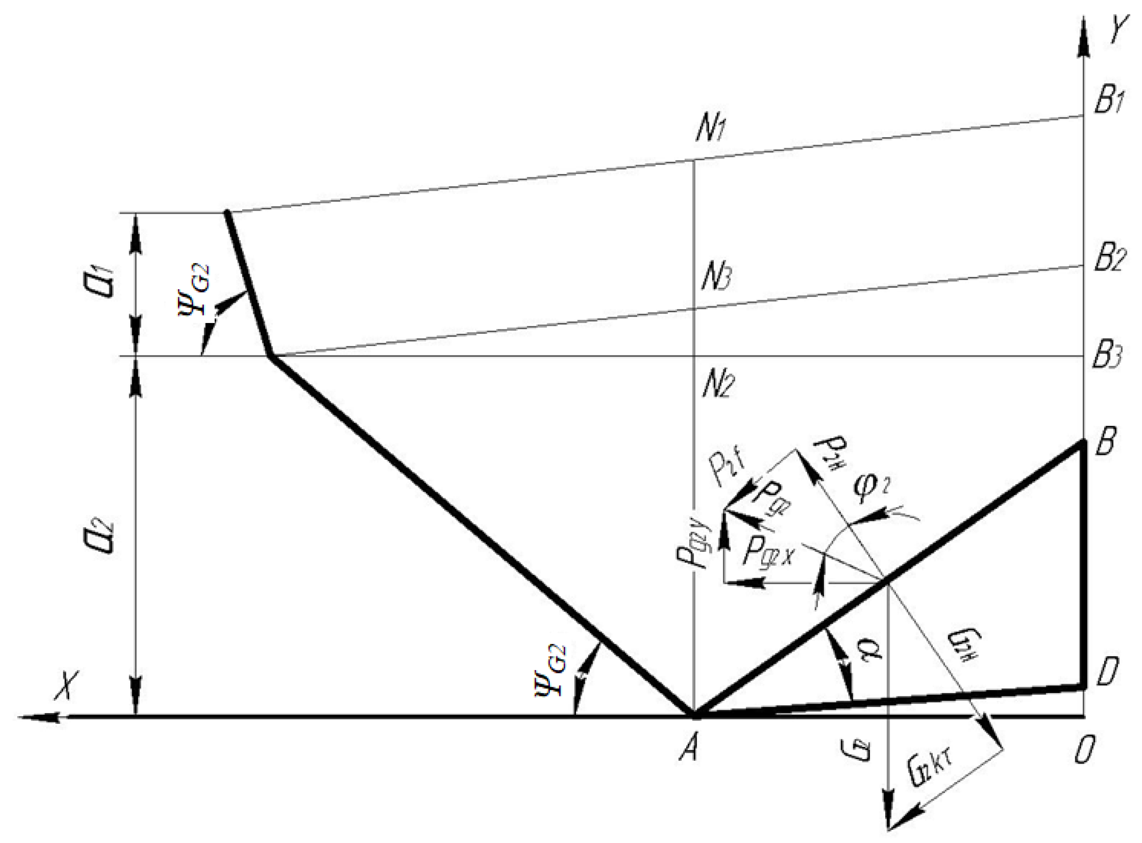
When the soil moves along the wedge surface ABD, its weight generates a normal reaction force on the working surface AB and a friction force . We decompose the weight of the soil layer G2 into a normal component G2H and a tangential component G2τ relative to the wedge surface AB (Figure 7).
Figure 7.
Force diagram acting on a two-edged wedge due to the weight of the soil layer.
Since the working surface AB of the wedge is in contact with the second layer, the components of the soil weight are equal to:
where —normal gravity force of the formation on the surface of the wedge AB, N;
—tangential force of gravity of the formation on the surface of the wedge AB, N.
The force G2H generates a normal reaction on the wedge surface, , while the force G2τ resists the movement of the soil layer along the plane AB.
When the soil layer moves along the working surface of the wedge, the normal force P2K generates a friction force equal to:
where —friction force of the second layer soil on the wedge, N;
—normal reaction acting on the wedge, N.
The resultant force of and the reaction of the wedge working surface due to the weight of the soil layer is equal to:
The weight force of the soil layer on the working surface of the wedge ABD:
where —gravity force of the formation on the working surface of the wedge, N;
—length of the wedge working surface.
We substitute the values of GK into the Expression (21) and project the force Pq2 onto the x-axis, obtaining:
The total resistance of the double-edged wedge (share) consists of the soil shear resistance forces, the weight of the soil layer and the dynamic pressure of the layer. The projections of these forces on the horizontal axis create the drawbar resistance of the wedge and are determined by Formulas (14)–(16) and (22).
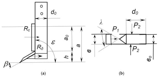
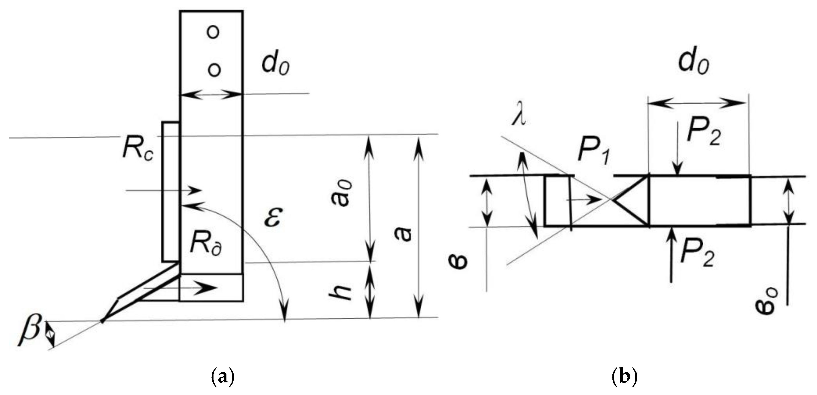
Studies established the influence of the structural parameters of the chisel shank and soil properties on the draft resistance [43,44,45,46], which can be determined by the Expression (23):
where —working depth of the chisel shank, m; B0 is the thickness of the chisel shank, m;
—angle of the shank relative to the furrow bottom, degrees;
—specific soil pressure on the front faces of the shank, N/m2;
—specific soil pressure on the side faces of the shank, N/m2;
—shank width, m;
λ—shank (knife) tip angle, degrees;
f—soil-to-steel friction coefficient.
The design scheme is shown in Figure 8, and the results of the calculations using Equation (23) showed the traction resistance of the chisel shank to be 4.2 kN at a thickness of 20 mm and 4.9 kN at a thickness of 30 mm.
Figure 8.
Chisel calculation scheme; (a) side view; (b) top view.
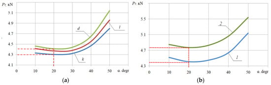
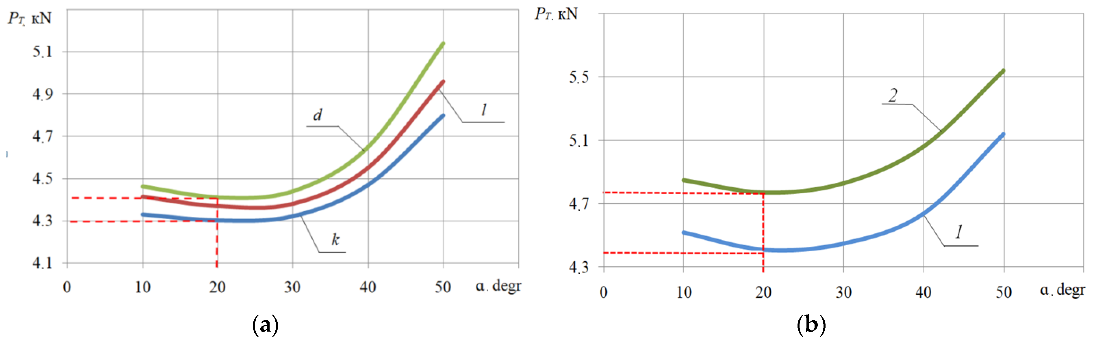
Thus, the obtained equations relate the parameters of the chisel working element to the physical and mechanical properties of soil layers and its movement speed. Using the presented equations, which describe the traction resistance of the chisel working element, calculations were carried out for the typical physical and mechanical properties of soils in the northern region of the Republic of Kazakhstan (Figure 9a,b).
Figure 9.
The influence of shank thickness, chisel width and chisel angle relative to the furrow bottom on the traction resistance of the chisel: (a) the influence of chisel angle on traction resistance at 20 mm shank thickness; (b) the influence of shank thickness with a chisel width of 50 mm. 1—a shank thickness of 20 mm; 2—a shank thickness of 30 mm; chisel width: k—40 mm; l—50 mm; d—60 mm.
It was established that the traction resistance of the working element decreases and reaches a minimum value at angles of 20–22 degrees if the angle of the chisel shank relative to the bottom of the furrow increases. A further increase in the angle contributes to a rise in traction resistance. This pattern is observed for both studied shank variants. The traction resistance of the shank with a thickness of 20 mm is lower than that of the shank with a thickness of 30 mm at all values of the chisel angle.
3.2. Experimental Studies on Refining the Parameters of the Working Element for Chiseling (Chisel) and Justifying the Design and Technological Scheme
Studies were previously conducted to substantiate the design and operational parameters of the slot cutter, as well as the safety device for the cutter shank [47,48].
Experimental studies on refining the parameters of the working element for chiseling (chisel) and justifying the design and technological scheme were carried out in the fields of “Kostanay Research Institute of Agriculture” LLP.
The conditions for conducting experimental studies in the soil layer of 0–30 cm had the following average values: soil hardness is 5.5 MPa, moisture content is 13.3% and bulk density is 1.32 g/cm3. The field background consisted of cereal stubble.
The studies were conducted to determine the influence of the physical and mechanical properties of the soil and the parameters of the working element on the traction resistance when justifying the parameters of the chisel. The obtained experimental data were compared with the results of theoretical studies.
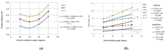
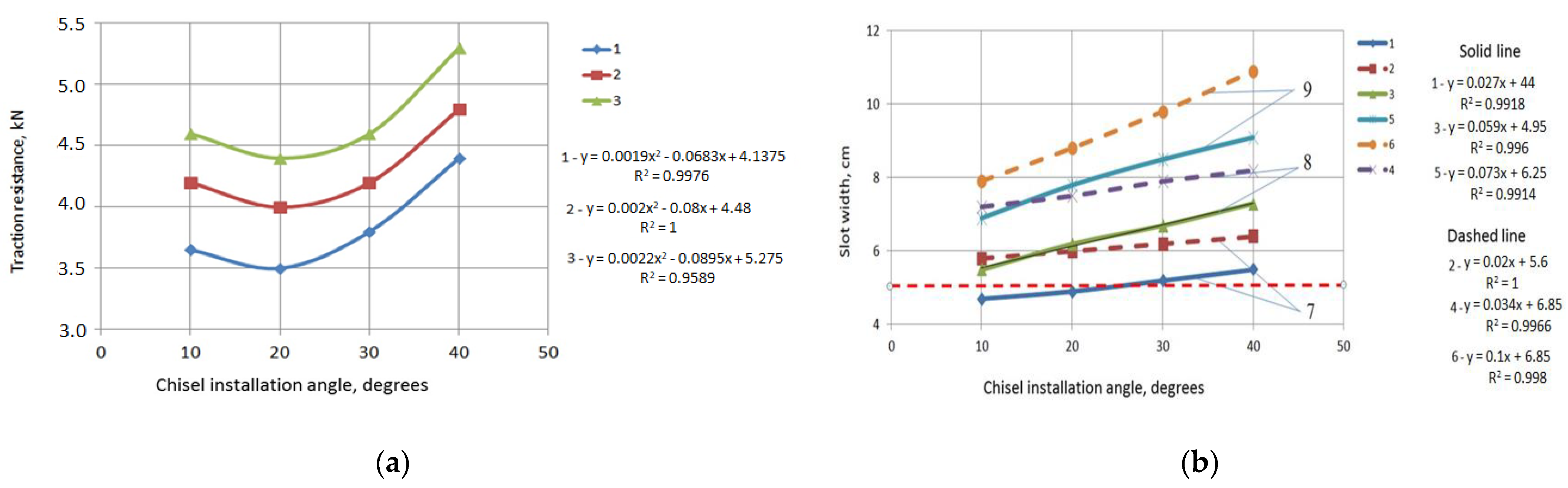
The results of the studies (Figure 10a,b) showed that an increase in the chisel angle from 10 to 20 degrees contributes to a decrease in traction resistance by 0.25–0.30 kN at a movement speed of 8.2 km/h, while a further increase in the angle from 20 to 40 degrees leads to an increase in traction resistance by 1.0–1.1 kN.
Figure 10.
The influence of shank thickness, chisel angle and chisel width on the traction resistance of the chisel: (a) a shank thickness of 20 mm; (b) a shank thickness of 30 mm; chisel width:1—40 mm; 2—50 mm; 3—60 mm.
An increase in the chisel width to 50 mm and then to 60 mm contributes to an increase in traction resistance by 0.3–0.4 kN, while the nature of the traction resistance dependencies does not change. The minimum traction resistance is provided by a chisel with a width of 40 mm, and the maximum by one with a width of 60 mm.
An increase in shank thickness from 20 to 30 mm contributes to a rise in traction resistance by 13–15%. The minimum traction resistance is provided by a chisel with a shank thickness of 20 mm, a chisel width of 40 mm and a chisel angle of 20 degrees.
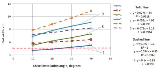
Chiseling of stubble fields consists of loosened strips with unworked interrows, with a slit formed in the center of the strip. The slit width is one of the most significant indicators, as it affects the intensity of soil moisture evaporation and the amount of stubble preserved. According to the recommended requirements for the chiseling operation, the slit width should not exceed 5 cm, the width of the loosened strip should not exceed 50 cm, stubble preservation should be at least 80% and the field surface roughness should not exceed 8 cm [49].
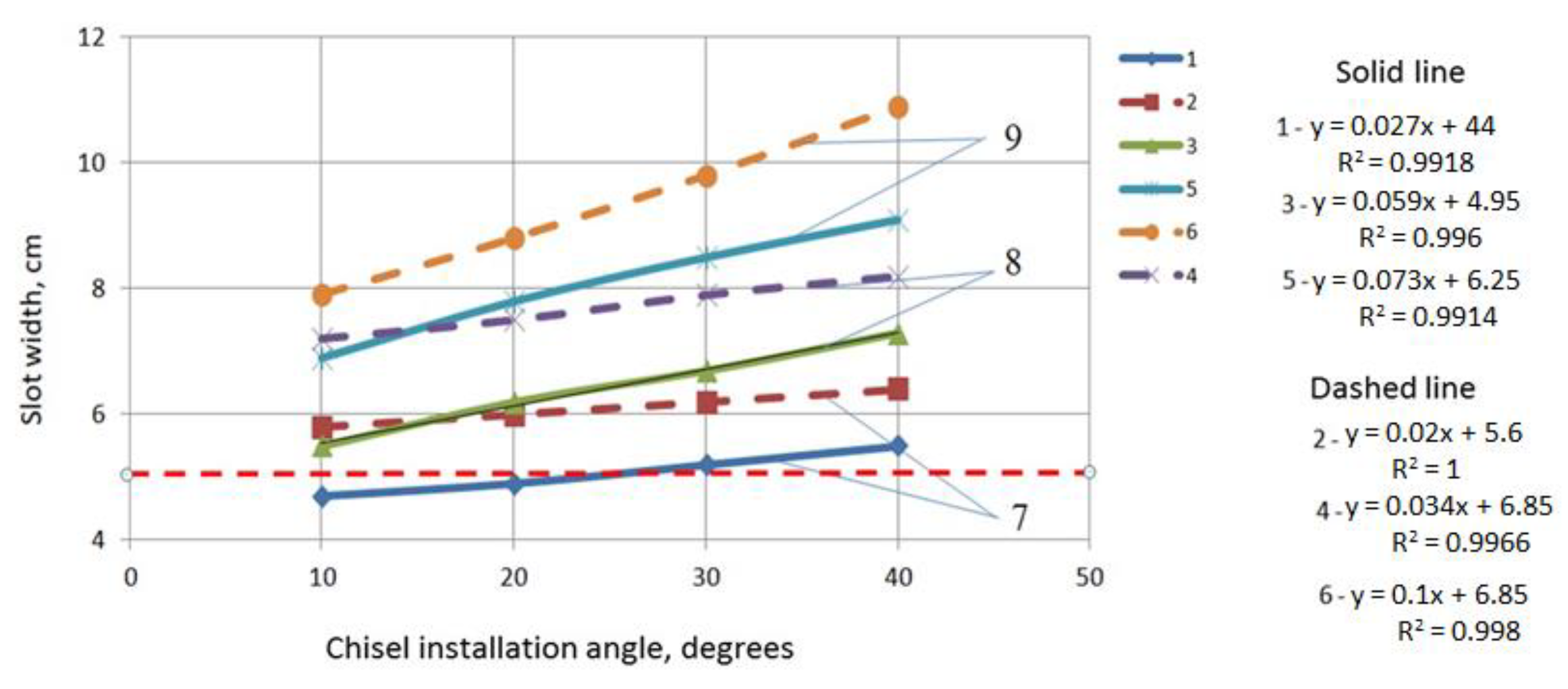
It was established that an increase in the chiseling angle from 10 to 40 degrees increases the slit width (Figure 11), which leads to a wider slit. An increase in shank thickness from 20 to 30 mm also increases the slit width.
Figure 11.
Effect of shank thickness, chisel angle, and chisel width on slit width; shank thickness (solid line)—20 mm; shank thickness (dashed line)—30 mm; chisel width: 7—40 mm; 8—50 mm; 9—60 mm.
The chisel with a chisel width of 40 mm and a shank thickness of 20 mm provides the required indicator at a movement speed of 8.2 km/h and chisel angles of 10 and 20 degrees. Chisels with 50 and 60 mm widths form a slit wider than the normative requirements in all experimental variants. The recommended slit width is provided by a chisel with a shank thickness of 20 mm, a chisel width of 40 mm and angles of 10 and 20 degrees. At the same time, the chisel with a 20-degree angle has lower traction resistance.
Thus, according to the indicators of traction resistance and slit width, the working element should have the following optimal parameters: shank thickness of 20 mm, chisel width of 40 mm, and chisel installation angle of 20 degrees (chiseling angle).
The travel speed of the machine ranged from 6.0 to 10.8 km/h when determining the influence of travel speed and design–technological schemes on the width of the loosened strip, deviation from the set working depth, stubble preservation, ridge height and traction resistance.
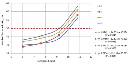
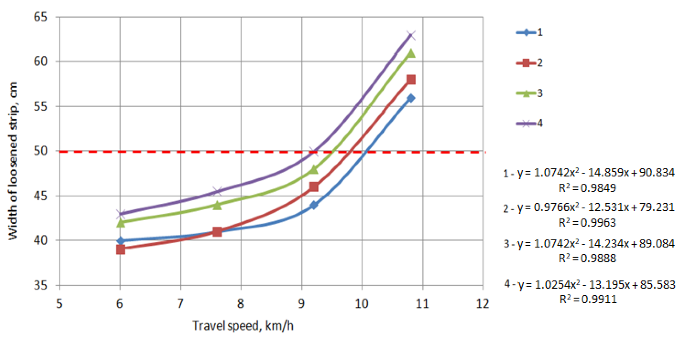
Determining the influence of travel speed and design–technological schemes on the width of the loosened strip showed that at travel speeds of 6.0–9.1 km/h, all studied schemes loosened a strip up to 50 cm wide, which corresponds to agronomic requirements (Figure 12).
Figure 12.
Effect of travel speed and design–technological schemes on the width of the loosened strip; 1 is scheme №1; 2 is scheme №2; 3 is scheme №3; 4 is scheme № 4.
An increase in travel speed to 10.8 km/h increases the width of the loosened strip to 52–57 cm. At this speed mode, none of the design–technological schemes provide the required parameters of the loosened strip.
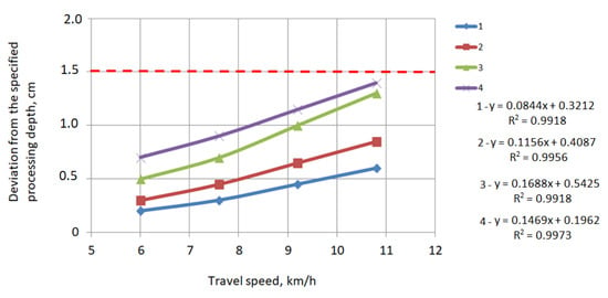
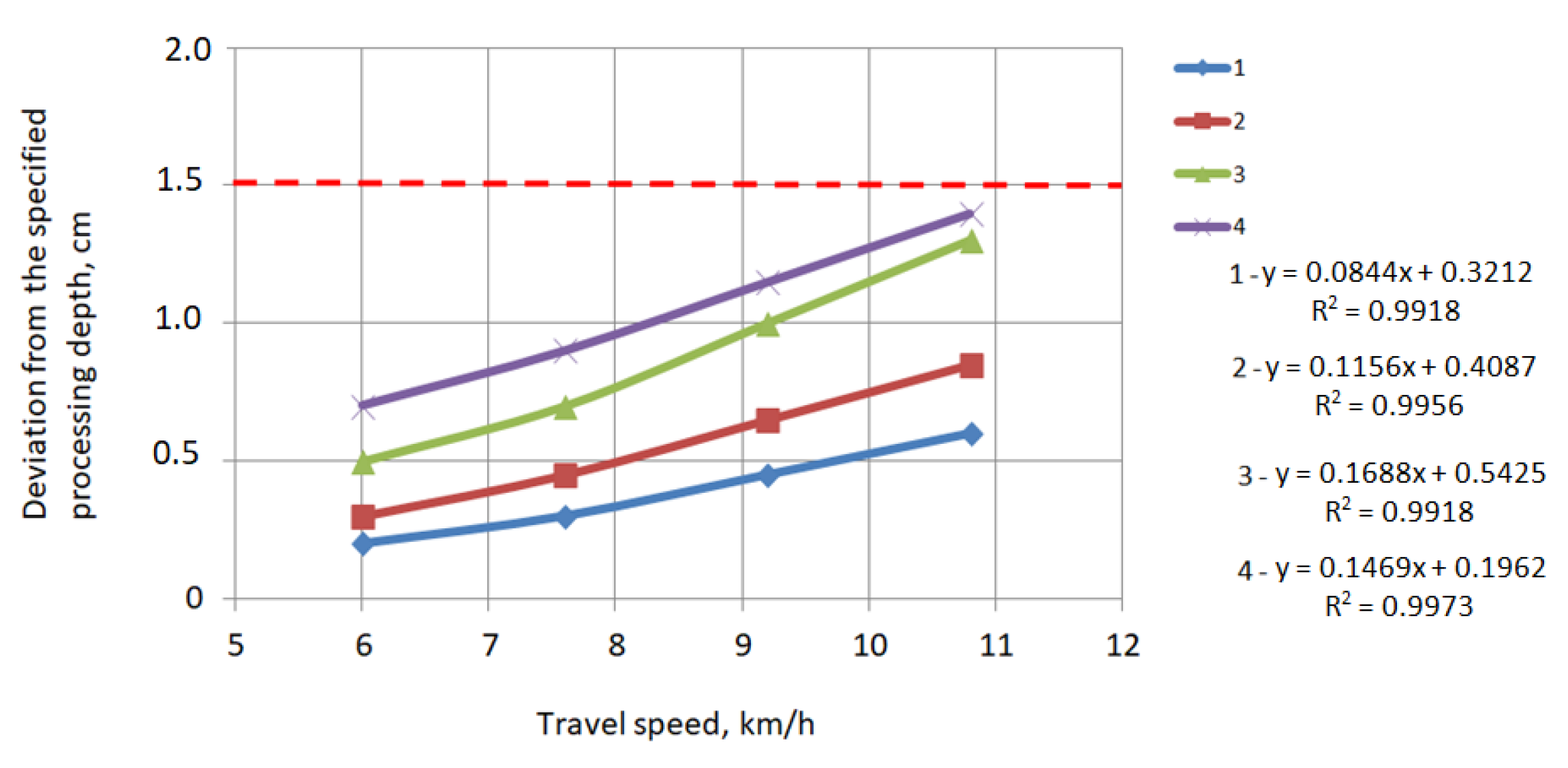
When determining the influence of travel speed and design–technological schemes on deviation from the set working depth, it was established that all studied schemes stably perform the technological process at a travel speed of 6.0–10.8 km/h. According to Figure 13, the root-mean-square deviation does not exceed 1.5 cm, which meets the agronomic requirements.
Figure 13.
Influence of travel speed on working-depth deviation; 1 is scheme №1; 2 is scheme №2; 3 is scheme №3; 4 is scheme №4.
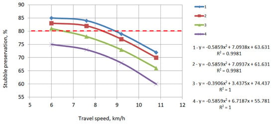
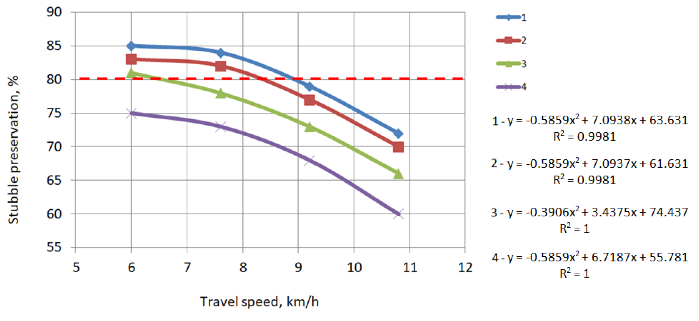
The evaluation of the influence of travel speed and design–technological schemes on stubble preservation showed that schemes No. 1, No. 2 and No. 3 provide the required stubble preservation indicator (no less than 80%) on the field surface at a travel speed of 6.0 km/h (Figure 14). At a travel speed of 7.6 km/h, the required stubble preservation indicator on the field surface (82–84%) is provided by schemes No. 1 and No. 2.
Figure 14.
Influence of travel speed on stubble preservation; 1 is scheme №1; 2 is scheme №2; 3 is scheme №4; 4 is scheme №3.
The stubble content on the field surface for schemes No. 1, No. 2, and No. 3 becomes less than 80% with an increase in the travel speed of the machine to 9.1–10.8 km/h. Scheme No. 4 does not provide the required stubble preservation indicator on the field surface at all speed modes (Figure 14).
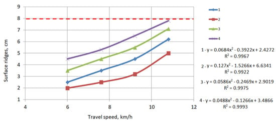
An increase in travel speed increases the ridge height when determining the influence of travel speed and design–technological schemes on ridge height (Figure 15).
Figure 15.
Influence of travel speed on ridge height; 1 is scheme №1; 2 is scheme №2; 3 is scheme №3; 4 is scheme №4.
According to Figure 15, at a travel speed of 6.0–10.8 km/h, all studied schemes form ridges with a height of no more than 8 cm, which corresponds to the agronomic requirements for performing the “soil chiseling” operation. The normative indicator is no more than 8 cm. At a travel speed of 6.0 km/h, all considered schemes form ridges on the surface with a height of 2.0–4.5 cm. An increase in travel speed to 10.8 km/h increases the ridge height, which ranges from 5.0 to 7.8 cm.
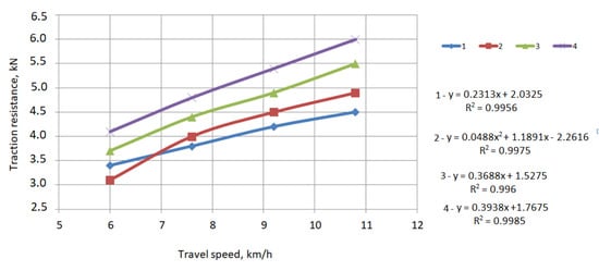
Schemes No. 1, 2, 3 and 4 were considered when determining the influence of design–technological schemes on traction resistance. The studies showed that an increase in travel speed increases the traction resistance (Figure 16). The design–technological schemes do not have a significant effect on traction resistance and the difference between the minimum and maximum traction resistance is 1.0–1.5 kN, as can be seen from the graph. The traction resistance values refer to a single row, while the implement design, depending on the working width, can have from five to eight rows, with a distance of 80 cm between adjacent rows. In this case, the traction resistance for an eight-row implement will range from 8.0 to 12.0 kN, which represents a significant load on the power unit.
Figure 16.
Influence of travel speed on the traction resistance of design–technological schemes; 1—scheme №1; 2—scheme №2; 3—scheme №4; 4—scheme №3.
Thus, the results of the studies on determining traction resistance showed that schemes No. 1 and No. 2 are the most promising for use in the design of the developed implement.
An experimental prototype of the chisel implement for working on compacted and stony fields was manufactured according to the justified parameters, and its tests were carried out under operational conditions.
The choice of the shape of the working element for deep loosening of the soil and the justification of its parameters affects the quality of the technological process and traction resistance; such conclusions are consistent with the results of research [23,26,50,51].
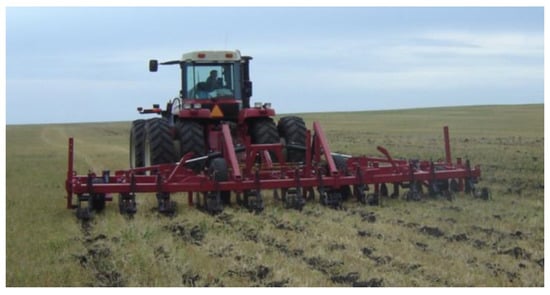
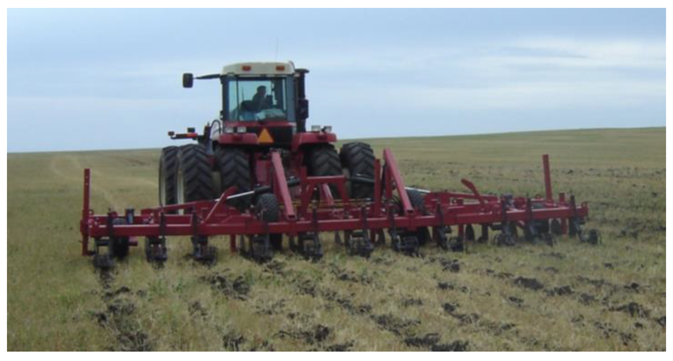
An experimental prototype of a slater for processing compacted and rocky backgrounds was manufactured using justified parameters and tested under production conditions. A “Buhler 2375” tractor was used as the power unit. The type of implement in operation is shown in Figure 17.
Figure 17.
The unit, consisting of a “Buhler 2375” tractor and an experimental chisel implement for working on compacted and stony fields. View in operation.
The conditions for conducting tests under operational conditions were as follows: The field background consisted of cereal stubble. The state of the treated soil layer during the studies was characterized by average indicators typical for soils of northern Kazakhstan in the autumn period. Soil hardness is 4.8 MPa, moisture content is 16.3% and bulk density is 1.39 g/cm3. These were the average values at a working depth of 0–30 cm.
The adjustment and regulation of the travel depth of the disk working elements and chisels, the force of the roller on the soil fractions and the position of the implement frame relative to the field surface were carried out before conducting tests under operational conditions for the experimental prototype.
Tests under operational conditions were conducted at travel speeds of 7.2, 8.6 and 10.0 km/h. The working depth of the chisel was 28.5–29.7 cm, and that of the disk working elements was 8.8–9.5 cm. The results of the evaluation of agronomic indicators are presented in Table 1. An increase in travel speed from 7.2 to 10.0 km/h increases the unevenness of the working depth from 1.2 to 1.4 cm. The obtained data do not exceed the requirements of the normative documentation (ND).
Table 1.
Agronomic indicators of the experimental chisel implement for working on compacted and stony fields.
An increase in travel speed increases indicators such as slit width (from 4.3 to 6.8 cm), width of the loosened strip (from 41 to 67 cm) and field surface roughness (from 4.2 to 8.8 cm), while the stubble content on the field surface decreases (from 78% to 62%). No clogging of the working elements occurred during the operation.
The analysis of the obtained values of functional indicators allows concluding that the experimental chisel implement performs the technological process with a quality corresponding to the agronomic requirements (ND) at travel speeds of 7.2 and 8.6 km/h. An increase in travel speed to 10 km/h increases the values of indicators such as the width of the loosened strip to 67 cm, slit width to 6.8 cm and field surface roughness to 8.8 cm. The values of these indicators exceed the normative requirements (ND). The stubble preservation indicator (no less than 80%) is not ensured at all speed modes.
The energy assessment of the experimental prototype was conducted simultaneously with the determination of agronomic indicators. The results of the energy assessment of the unit are presented in Table 2.
Table 2.
Energy assessment indicators of the experimental towed chisel implement for working on compacted and stony fields in a unit with a “Buhler 2375” tractor.
The productivity of the unit, at a working width of 7.2 m and a travel speed of 8.6 km/h, was 6.2 ha per hour of main time, and the traction resistance was 53.4 kN. The hourly fuel consumption was 48.7 kg. The power consumed by the unit was 127.6 kW, while the specific energy consumption for the unit with the “Buhler 2375” tractor was 74.1 MJ/ha.
The allowable load on the power unit according to traction and coupling indicators is ensured at travel speeds of 8.6 and 10.0 km/h under the given test conditions, as the analysis of the obtained results shows. The created chisel implement for working on compacted and stony fields provides the required quality of treatment at a travel speed of 8.6 km/h.
4. Discussion
An analysis of the results of similar studies conducted previously shows that the width of the share, the shape of the slit cutter, its optimal parameters such as height, width and the method of attachment to the frame differ significantly in all the working bodies being developed. It should be noted that the closest value for all the developed slit-cutting deep rippers has a chisel crushing angle, which is within 20–30 degrees [22,52].
The traction force of the slitter and the tool as a whole depends on the type (shape) and parameters of the working element, the tool’s working width, and the speed of movement. The traction force trend is such that with increasing chisel width, the thickness and width of the slitter’s shank, and the speed of movement, the traction resistance increases [14,25,53]. The type and parameters of the working element also have a significant impact on agrotechnical indicators such as disturbance of the soil cover, preservation of stubble, width and depth of the loosened strip [54,55], which is confirmed by the results of our research.
Currently, there is no consensus regarding the shape and parameters of the soil-working tool or the structural and technological scheme for soil tillage. John Deere manufactures the “Till-Ripper” with rigid shanks, while Unverferth produces the “Zone-Builder” with C-shaped shanks; both manufacturers maintain that their respective equipment offers maximum efficiency. Research results indicate that a straight slot-cutting tine has a draft resistance of 6.78 kN, a C-shaped tine has 4.58 kN, and a tine set at a specific angle to the furrow bottom has a draft resistance of 7.39 kN. Furthermore, the volume of soil structure disruption during operation is 0.0325 m3 for the straight tine, 0.312 m3 for the C-shaped tine, and 0.561 m3 for the tine set at a specific angle to the furrow bottom [23,26]. Apart from soil degradation, no other parameters characterizing agrotechnical indicators were determined in these studies. Our research has established that using a straight slot-cutter shank with a thickness of 20 mm and a 40 mm wide chisel—set at a 20-degree angle to the furrow bottom—results in a draft resistance of 3.51 kN (Figure 10a). At the same time, the agrotechnical performance indicators meet the requirements of regulatory documentation. Using the developed tool for slitting compacted and rocky soils will improve tillage quality, which will promote the active accumulation and retention of soil moisture. Experience shows that this approach to agricultural technology contributes to increased crop yields.
5. Conclusions
- 1.
- A calculation scheme of the interaction between the chisel implement working element and a soil layer with two clearly defined layers having different physical and mechanical properties was developed. Mathematical modeling was carried out and the optimal chisel installation angles for different shank widths were determined. It was established that the minimum traction resistance of the working element is achieved at chisel installation angles of 10–22 degrees.
An increase in the chisel installation angle relative to the furrow bottom from 10 to 20 degrees decreases the traction resistance, while a further increase in the angle from 20 to 40 degrees increases the traction resistance. An increase in the shank thickness of the chisel implement leads to an increase in its traction resistance.
- 2.
- The results of the conducted laboratory and field studies showed that an increase in the chiseling angle from 10 to 40 degrees and an increase in shank thickness increase the slit width. It has been established that the slot cutter—featuring a 40 mm chisel width, 20 mm shank thickness, and chisel installation angles of 10 and 20 degrees—achieves the required slot length. Chisels with widths of 50 and 60 mm form a slit exceeding the normative requirements in all experimental variants.
- 3.
- It was established that a shank with a thickness of 20 mm, a chisel width of 40 mm and a chiseling angle of 20 degrees has the minimum traction resistance. A shank with a thickness of 30 mm creates a traction resistance 15% higher than a shank with a thickness of 20 mm.
- 4.
- It has been determined that the design and technical configuration of the slotter must include a horizontally positioned cutting disk, a slot cutter equipped with a safety mechanism, and a localized-action rod-type packing roller. The slot cutter shank must have a thickness of 20 mm, the chisel a thickness of 40 mm, and the shattering angle must be 20 degrees. At an operating speed of 8.6 km/h, a slotter with these specifications ensures compliance with agrotechnical requirements regarding deviation from the target working depth and ridge height, as well as slot width, loosened strip width, and stubble preservation.
- 5.
- The production tests showed that the created chisel implement for working on compacted and stony fields provides the required quality during the performance of the technological process.
- 6.
- Research results have demonstrated that the developed slot cutter—designed for operation on over-compacted and stony soils—is a promising piece of equipment for energy- and moisture-conserving tillage technologies; it is recommended for inclusion in the future machinery system currently being developed for agricultural production in the Republic of Kazakhstan.
Author Contributions
All authors contributed equally to the conception, execution, data collection, data analysis, and writing of the manuscript, and critically revised the manuscript and approved the final version. All authors have read and agreed to the published version of the manuscript.
Funding
This study was funded by the Ministry of Agriculture of the Republic of Kazakhstan (Project No. BR24892784). Development of a machine system, fuel requirements, and fuel consumption standards for mechanized operations, as well as a sugar beet seeding machine.
Institutional Review Board Statement
Not applicable.
Informed Consent Statement
Not applicable.
Data Availability Statement
All data used in this study are publicly accessible at the following link: https://zenodo.org/uploads/20621233 (accessed on 10 July 2026).
Conflicts of Interest
Authors Alexey Derepaskin, Yurij Polichshuk, Yurij Binyukov, Artem Komarov, Anton Kuvaev and Nikolay Laptev was employed by Kostanay branch of Scientific Production Center of Agricultural Engineering, LLP. All authors declare that the research was conducted in the absence of any commercial or financial relationships that could be construed as a potential conflict of interest.
References
- Peralta, G.; Alvarez, C.R.; Taboada, M. Soil compaction alleviation by deep non-inversion tillage and crop yield responses in no tilled soils of the Pampas region of Argentina. A meta-analysis. Soil Tillage Res. 2021, 211, 105022. [Google Scholar] [CrossRef] [Scilit]
- Avila, R.; Schoenau, J.; King, T.; Si, B.; Grevers, M. Effects of subsoiling tillage on structure, permeability, and crop yields on compacted Solonetzic and Chernozemic dryland soils in Western Canada. Can. Biosyst. Eng./Genie Biosyst. Au Can. 2020, 62, 1.1–1.9. [Google Scholar] [CrossRef] [Scilit]
- Sharifnasab, H.; Soltani, E.; Karami, H.; Grądecka-Jakubowska, K.; Gancarz, M. Meta-analysis of tillage methods and their influence on wheat productivity. Int. Agrophys. 2024, 38, 345–351. [Google Scholar] [CrossRef] [Scilit] [PubMed]
- Li, L.; Guan, J.; Chen, S.; Zhang, X. Intermittent Deep Tillage on Improving Soil Physical Properties and Crop Performance in an Intensive Cropping System. Agronomy 2022, 12, 688. [Google Scholar] [CrossRef] [Scilit]
- Zhu, X.; Peng, W.; Xie, Q.; Ran, E. Effects of Soil Compaction Stress Combined with Drought on Soil Pore Structure, Root System Development, and Maize Growth in Early Stage. Plants 2024, 13, 3185. [Google Scholar] [CrossRef] [Scilit] [PubMed]
- Ma, Y.; Zhu, Y.; Li, J.; Li, Z.; Zhao, D.; Qu, Z.; Zhou, X.; Zhao, W.; Wei, X.; Sun, J.; et al. Addressing Black Soil Compaction: An Integrated Analysis of the Mechanisms, Efficacy, and Future Directions of Conservation Tillage. Agronomy 2026, 16, 274. [Google Scholar] [CrossRef] [Scilit]
- Xiao, H.; Bian, Z.; Xu, J.; Li, S.; Xiao, M.; Guo, M.; Bu, X.; Rafiq, M.; Cheng, C. Adaptation of northern grasses for combating desertification around Poyang Lake, China. Turk. J. Agric. For. 2025, 49, 912–922. [Google Scholar] [CrossRef] [Scilit]
- Akshalov, K.; Kuzhinov, M. Principles of Land Use in Kazakhstan at the Present Stage: Status, Prospects. In Nature Conservation and Regional Development: Harmony and Conflicts (Year of Ecology in Russia). International Scientific-Practical Conference, Russia; Springer: Berlin/Heidelberg, Germany, 2017; pp. 100–104. [Google Scholar]
- Schneider, F.; Don, A.; Hennings, I.; Schmittmann, O.; Seidel, S. The effect of deep tillage on crop yield-What do we really know? Soil Tillage Res. 2017, 174, 193–204. [Google Scholar] [CrossRef] [Scilit]
- Kuvaev, A. Primary Tillage of Stubble Fields in Northern Grain-Producing Regions of Kazakhstan and Modern Implements for Its Performance. 3I Intell. Idea Innov. 2018, 2, 57–64. [Google Scholar]
- Ordonez-Morales, K.; Cadena-Zapata, M.; Zermeno-Gonzalez, A.; Campos-Magana, S. Effect of Tillage Systems on Physical Properties of a Clay Loam Soil under Oats. Agriculture 2019, 9, 62. [Google Scholar] [CrossRef] [Scilit]
- Hargreaves, P.; Baker, K.; Graceson, A.; Bonnett, S.; Ball, B.; Cloy, J. Soil compaction effects on grassland silage yields and soil structure under different levels of compaction over three years. Eur. J. Agron. 2019, 109, 125916. [Google Scholar] [CrossRef] [Scilit]
- Komarov, A. Modern Implements for Soil Chiseling. In Scientific and Technical Support of Agro-Industrial Complex in the Implementation of the State Program for Agricultural Development until 2020: Proceedings of the International Scientific-Practical Conference, Kurgan, Russia; IOP publishing: Bristol, UK, 2019; pp. 272–276. [Google Scholar]
- Wang, Y.; Osman, A.N.; Zhang, D.; Yang, L.; Cui, T.; Zhong, X. Optimized design and field experiment of a staggered vibrating subsoiler for conservation tillage. Int. J. Agric. Biol. Eng. 2019, 12, 59–65. [Google Scholar] [CrossRef] [Scilit]
- Nebo, G.; Manyevere, A.; Araya, T.; Tol, J. Short-Term Impact of Conservation Agriculture on Soil Strength and Saturated Hydraulic Conductivity in the South African Semiarid Areas. Agriculture 2020, 10, 414. [Google Scholar] [CrossRef] [Scilit]
- Greyling, M.; Van Rooy, J. Hydrogeological Properties of Gypseous soils in South Africa. South Afr. J. Geol. 2019, 122, 389–396. [Google Scholar] [CrossRef] [Scilit]
- Karipov, R.K.; Zhumagulov, I.I.; Didenko, S.V. Resource-Saving Technologies in the Dry-Steppe Zone of Northern Kazakhstan. Sci. World 2015, 3, 120–122. [Google Scholar]
- Astafyev, V.L. Techniques for Moisture Accumulation and Preservation in Water-Saving Technologies and Equipment for Their Implementation. In Proceedings of the Scientific Support for the Implementation of State Programs of Agro-Industrial Complex and Rural Areas: Proceedings of the International Scientific-Practical Conference, Kurgan, Russia, 27 March 2017; pp. 38–45. [Google Scholar]
- Rathinavel, S. Effects of Subsoiler on Farm Fields—A Review. Int. J. Curr. Microbiol. Appl. Sci. 2020, 9, 554–560. [Google Scholar] [CrossRef] [Scilit]
- Zeng, Z.W.; Ma, X.; Chen, Y.; Qi, L. Modelling residue incorporation of selected chisel ploughing tools using the discrete element method (DEM). Soil Tillage Res. 2020, 197, 104505. [Google Scholar] [CrossRef] [Scilit]
- Becker, R.K.; Barbosa, E.; Giarola, N.F.B.; Kochinski, E.G.; Povh, F.P.; Paula, A.L.d.; Cherubin, M.R. Mechanical Intervention in Compacted No-Till Soil in Southern Brazil: Soil Physical Quality and Maize Yield. Agronomy 2022, 12, 2281. [Google Scholar] [CrossRef] [Scilit]
- Lou, S.; He, J.; Lu, C.; Liu, P.; Li, H.; Zhang, Z. A Tillage Depth Monitoring and Control System for the Independent Adjustment of Each Subsoiling Shovel. Actuators 2021, 10, 250. [Google Scholar] [CrossRef] [Scilit]
- Martinez-Reyes, E.; Morales-Morales, C.; Ramos-Cantu, L.; Castro-Bello, M.; Gonzalez-Lorence, A. Subsoiler Tool with Bio-Inspired Attack Edge for Reducing Draft Force during Soil Tillage. AgriEngineering 2024, 6, 2678–2693. [Google Scholar] [CrossRef] [Scilit]
- Song, W.; Ren, L.; Wang, J.; Ma, Y.; Guo, Y.; Han, M.; Zhao, H. Methods for Constructing Soil Dynamic Models Under Intelligent Cultivation: Dynamic Interaction Mechanisms Between Farming Tools with Complex Structures and Soil. Agriculture 2025, 15, 1355. [Google Scholar] [CrossRef] [Scilit]
- Wang, Y.M.; Lu, C.J.; Fan, J.J.; Zhang, X.; Chen, K.; Chen, J.; Li, X. Evaluating the effects of subsoiler type and spacing on tillage resistance and soil conservation with DEM simulation and field experiment. Int. J. Agric. Biol. Eng. 2025, 18, 115–123. [Google Scholar] [CrossRef] [Scilit]
- Odey, S.O.; Manuwa, S.I. Subsoiler Development Trend in the Alleviation of Soil Compaction for Sustainable Agricultural Production. Int. J. Eng. Invent. 2018, 7, 29–38. [Google Scholar]
- Kondratiuk, A.; Šarauskis, E.; Sheludchenko, B.; Kukharets, S.; Jasinskas, A.; Zabrodskyi, P.; Shubenko, V. Substantiation of the Use of a Flexible Chain-Type Subsoiler for Improving the Agrotechnological Properties of Soil. Sustainability 2024, 16, 5355. [Google Scholar] [CrossRef] [Scilit]
- Xu, X.; Jing, P.; Yao, Q.; Chen, W.; Meng, H.; Li, X.; Qi, J.; Peng, H. Parameter Optimization and Test for the Pulse-Type Gas Explosion Subsoiler. Agriculture 2024, 14, 1417. [Google Scholar] [CrossRef] [Scilit]
- GOST 20915-2011; Testing of Agricultural Tractors and Machines. Procedure for Determination of Test Conditions. Standartinform: Moscow, Russia, 2013; 27p. Available online: https://files.stroyinf.ru/Data2/1/4293788/4293788522.pdf (accessed on 5 June 2026).
- ST RK1560-2006; Testing of Agricultural Machinery. Machines and Implements for Deep Soil Tillage. Methods for Evaluating Functional Indicators. Committee for Technical Regulation and Metrology of the Ministry: Astana, Kazakhstan, 2006.
- GOST 33736-2016; Agricultural Machinery. Machines for Deep Soil Tillage. Test Methods. FGUP Standartinform: Moscow, Russia, 2017; p. 39. Available online: https://files.stroyinf.ru/Data/641/64138.pdf (accessed on 5 June 2026).
- Derepaskin, A.I.; Polichshuk, Y.V.; Shayakhmetov, A.B.; Bedych, T.V.; Kuvaev, A.N.; Tokarev, I.V. Influence of Parallel Driving Systems and Differentiated Fertilizer Application on the Efficiency of Using Machine and Tractor Units in the Southern Chernozem of North Kazakhstan. Acta Univ. Agric. Silvic. Mendel. Brun. 2023, 71, 43–51. [Google Scholar] [CrossRef] [Scilit]
- Kuvaev, A.N.; Derepaskin, A.I.; Tokarev, I.V.; Polichshuk, Y.V.; Binyukov, Y.V.; Kukhar, V.S.; Semibalamut, A.V. Optimizing Cultivator-Fertilizer Performance with Tractor-Mounted Configuration in Northern Kazakhstan. Int. J. Agric. Biosci. 2025, 14, 674–682. [Google Scholar] [CrossRef] [Scilit] [PubMed]
- GOST R 52777-2007; Agricultural Machinery. Methods of Energy Assessment. FGUP Standartinform: Moscow, Russia, 2007; p. 7. Available online: https://meganorm.ru/Data2/1/4293835/4293835734.pdf (accessed on 5 June 2026).
- Vedenyapin, G.V. General Methodology of Experimental Research and Processing of Experimental Data; Kolos: Moscow, Russia, 1967; 159p. [Google Scholar]
- Dospekhov, B.A. Field Experiment Methodology; Agropromizdat: Moscow, Russia, 1985; 351p. [Google Scholar]
- Blokhin, V.G.; Gludkin, O.P.; Gurov, A.I.; Khanin, M.A. Modern Experiment: Preparation, Conduct, Analysis of Results; RadioiSvyaz: Moscow, Russia, 1997; 232p. [Google Scholar]
- Goryachkin, V.P. Agricultural Mechanics (General Theory of Machines). Collected Works in 3 Volumes; Kolos: Moscow, Russia, 1965; Volume 1, 720p. [Google Scholar]
- Vinogradov, V.I. Interaction of Moldboard Plow Working Elements with Soil and Methods of Reducing Plowing Energy Consumption. Ph.D. Thesis, Saratov Agricultural Institute, Saratov, Russia, 1967; 74p. [Google Scholar]
- Gukov, Y.S. Mechanical and Technological Justification of Energy-Saving Mechanization Means for Soil Tillage in Ukraine. Ph.D. Thesis, UkrNIIMESKH, Glevakha, Ukraine, 1998; 33p. [Google Scholar]
- Kapov, S.I. Mechanical and Technological Foundations for the Development of Energy-Saving Soil-Tillage Machines. Ph.D. Thesis, ChGAU, Chelyabinsk, Russia, 1999; 36p. [Google Scholar]
- Burchenko, P.N. Mechanical and Technological Foundations of Next-Generation Soil-Tillage Machines: Monograph; VIM: Moscow, Russia, 2002; 212p. [Google Scholar]
- Kostritsin, A.K. Justification of the Type and Parameters of Working Elements for Plows and Non-Moldboard Rippers for Furrow Bottom Chiseling. Proc. VIM 1981, 90, 91–108. [Google Scholar]
- Rakhimov, R.S.; Gayupov, K.E.; Shemetov, N.A. Influence of Design Parameters of the Chisel on the Traction Resistance of the Flat-Chisel. Proc. ChIMESKh 1979, 149, 36–40. [Google Scholar]
- Sineokov, G.N. Theory and calculation of soil-cultivating machines; Mechanical engineering: Moscow, Russia, 1977; 328p, Available online: https://rusneb.ru/catalog/000200_000018_rc_2271917 (accessed on 15 July 2026).
- Osadchiy, A.P. Mechanics of Shearing and Fracture of Soil Layer by a Wedge. Ph.D. Thesis, Ministry of Agriculture, Volgograd, Russia, 1970; 33p. [Google Scholar]
- Polishchuk, Y.V.; Derepaskin, A.I.; Laptev, N.V.; Komarov, A.P. Justification of rational design parameters for a slotting implement for autumn tillage of stubble fields, designed for tractors of traction class 8. Tract. Agric. Mach. 2020, 87, 49–55. [Google Scholar] [CrossRef] [Scilit]
- Polishchuk, Y.V.; Derepaskin, A.I.; Laptev, N.V.; Komarov, A.P. Justification of the Parameters of the Slot Cutter Safety Device. 3i Intell. Idea Innov. 2026, 1, 180–192. [Google Scholar] [CrossRef] [Scilit]
- Aniskin, V.I.; Artyushin, A.A. Initial Requirements for Basic Machine Technological Operations in Crop Production; Ministry of Agriculture of the Russian Federation: Moscow, Russia, 2005; 270p.
- Sun, J.; Wang, Y.; Ma, Y.; Tong, Y.; Zhang, Z. DEM simulation of bionic subsoilers (tillage depth > 40 cm) with drag reduction and lower soil disturbance characteristics. Adv. Eng. Softw. 2018, 119, 30–37. [Google Scholar] [CrossRef] [Scilit]
- Lou, S.; He, J.; Li, H.; Wang, Q.; Lu, C.; Liu, W.; Liu, P.; Zhang, Z.; Li, H. Current Knowledge and Future Directions for Improving Subsoiling Quality and Reducing Energy Consumption in Conservation Fields. Agriculture 2021, 11, 575. [Google Scholar] [CrossRef] [Scilit]
- Xu, S.; Tao, G.; Yi, S.; Wang, S.; San, Y. Design and testing of a winged subsoiler shovel for strip minimum-tillage deep loosening fertiliser machine. INMATEH-Agric. Eng. 2025, 75, 910–922. [Google Scholar] [CrossRef] [Scilit]
- Al-Jarrah, M.A.A.-M.; Dahham, G.A.; Hamood, H.A. Draft force and efficiency of soil loosening for different designs of subsoiler plow shanks. Mesop. J. Agric. 2025, 53, 1–15. [Google Scholar] [CrossRef] [Scilit]
- Igamberdiyev, A.; Farmonov, E.; Alikulov, S.; Usmanova, G.; Sharipov, Z. Justification of parameters of working body of deep loosener. E3S Web Conf. 2023, 365, 04014. [Google Scholar] [CrossRef] [Scilit]
- Sedara, A.M.; Abdeldayem, M.A.; de Freitas, F.P.G.; Mehari, T.Z. Optimization of subsoiler design using similitude-based DEMsimulation and soil bin testing on cohesive-frictional artificial soil. J. Terramechanics 2025, 117, 101026. [Google Scholar] [CrossRef] [Scilit]

Disclaimer/Publisher’s Note: The statements, opinions and data contained in all publications are solely those of the individual author(s) and contributor(s) and not of MDPI and/or the editor(s). MDPI and/or the editor(s) disclaim responsibility for any injury to people or property resulting from any ideas, methods, instructions or products referred to in the content. |
© 2026 by the authors. Licensee MDPI, Basel, Switzerland. This article is an open access article distributed under the terms and conditions of the Creative Commons Attribution (CC BY) license.