


Abstract
To address persistent problems such as clogging, high digging resistance, incomplete soil removal, and severe pod loss during the operation of shovel-chain peanut harvesters, a hybrid excavation approach was developed based on an in-depth analysis of the mechanical interaction between the peanut plant–soil complex (hereafter referred to as the “complex”) and the harvesting mechanism. The proposed approach integrates vertical and horizontal excavation directions to enhance soil fragmentation and reduce operational resistance. A progressive soil disintegration process was introduced, in which the complex undergoes lateral and longitudinal compression-bending deformation during movement. A driven soil–plant separation scheme was implemented through coordinated operation of upper conveying and lower combing–lifting mechanisms, promoting efficient and continuous material flow. A resistance-reducing digging device consisting of opposing round plow blades and horizontally sliding digging shovels was designed to minimize excavation resistance and soil adhesion. Meanwhile, an anti-clogging separation mechanism, integrating squeezing and feeding rollers and harrow-chain, was developed to improve soil removal and pod separation. Key structural and operational parameters—such as the chain-to-machine speed ratio, tooth-to-chain rotation speed ratio, harrow-tooth spacing ratio, and pushing-tooth transmission ratio—were optimized through theoretical analysis and prototyping. The final design also refined the number of pushing-tooth rows, squeezing and feeding roller geometry, conveying-tooth radius, and the configuration and distribution of rake and stick-tooth shafts. Field experiments were conducted using the developed prototype under sandy loam conditions (11–15% moisture content) with Yu Hua 22 peanut plants (35–40 cm height, 70 cm ridge spacing, 30 cm narrow-row spacing) at a working speed of 1.5–1.6 km·h−1. Results demonstrated that the prototype achieved average ground pod loss, buried pod, and soil carryover rates of 1.13%, 0.95%, and 7.87%, respectively. The entire operation proceeded smoothly without clogging, and continuous conveying of peanut plants was maintained. These findings confirm that the proposed combined excavation and separation system meets and in some respects exceeds the performance requirements for efficient peanut harvesting under typical field conditions.
1. Introduction
Peanuts are one of China’s most important oilseed and cash crops [1], with an annual cultivation area of about 4.69 million hectares, accounting for approximately 15.4% of the world’s total peanut-growing area. The country’s total production exceeds 17.9 million tons, representing 33.9% of global output, placing China first worldwide. In recent years, the mechanization level of peanut harvesting in China has developed rapidly. By 2016, the national average mechanized harvesting rate had reached 33.91%, while in major production regions such as Northeast China and the Huang–Huai–Hai Plain, the rate exceeded 80%, making a substantial contribution to the sustainable development of peanut production [2]. Currently, segmented harvesting remains the predominant practice in China’s peanut production. Among small- and medium-sized harvesters currently in use, the two main structural types are clamp-type and shovel-chain-type. The clamp-type harvester features advantages such as low operating resistance and orderly lateral plant placement after lifting. However, it is suitable only for ridge-planted peanuts and shows poor adaptability to variations in ridge spacing, row spacing, soil conditions, and plant morphology, often leading to missed harvests and excessive soil carryover. In contrast, shovel-chain-type harvesters exhibit better adaptability to flat planting, different ridge–row configurations, and varied soil and plant conditions, and they have therefore gained widespread adoption in recent years [1,2,3]. Nevertheless, as noted by researcher Hu Zhichao (2022), severe clogging, high operational resistance, and excessive pod loss remain three major challenges in the mechanized harvesting of peanuts in China that urgently require further resolution [4].
Mechanized harvesting is a core technology for boosting production efficiency and increasing growers’ income, and the United States has a long-standing research foundation in peanut harvesting machinery that dates back to the early 19th century. Building on this early research, the U.S. pioneered the two-stage mechanized harvesting method for peanuts as early as the 1960s, and to this day, it remains a global leader in producing the most advanced peanut harvesting machinery [5,6]. Companies such as KMC, AMADAS, and COLOMBO have developed peanut diggers based on chain-rake structures, which effectively fulfill the agronomic requirements of peanut cultivation. These harvesters perform particularly well under conditions of loose soil created by corn–peanut–cotton rotation systems and straw incorporation, where loose soil allows the peanut–soil complex to be easily separated with minimal operational resistance. Furthermore, prostrate and semi-prostrate peanut varieties, characterized by multiple branches, low centers of gravity, extensive horizontal pod distribution, and strong plant cohesion, maintain structural continuity during digging, separating, and conveying, thereby reducing the likelihood of clogging and incomplete soil removal. In addition, standardized planting patterns with consistent row spacing and plant spacing, coupled with suitable soil moisture at harvest, facilitate mechanized operations and reduce pod loss caused by soil adhesion or excessive plant density [7,8]. However, most peanut varieties grown in China are erect plants, which are taller, have fewer branches, and show weaker inter-plant adhesion. Combined with the country’s diverse soil textures and varying degrees of compaction, these factors limit the adaptability of imported American harvesters to local conditions, resulting in inadequate excavation and separation performance [9].
To address the limitations of shovel-chain peanut harvesters, Chinese agricultural engineers have conducted extensive studies, including mathematical modeling and analysis of digging resistance [10,11], development of oscillating-type peanut harvesters [12], design of digging and soil-removal mechanisms for combined harvesters [13], and proposal of streamlined and power-disc digging systems [14]. Other innovations include the development of dual-stage elevator-chain harvesters [15,16,17], comparative analyses between shovel-chain and shovel-roller mechanisms [18,19,20,21,22,23,24,25,26], and multi-row harvester component simulations [27]. Despite these advances, systematic investigations focusing on the key issues of clogging, excessive operational resistance, and high soil retention during operation remain limited. Similar operational problems have also been observed in related agricultural machinery such as chain-type potato diggers and field stone collectors, where clogging and high resistance continue to constrain [28,29,30]. Therefore, the present study aims to investigate the mechanical principles of peanut excavation, soil fragmentation, and plant–soil separation, and to design and experimentally evaluate a resistance-reducing and anti-clogging digging–separation device for chain-rake-type peanut harvesters.
2. Analysis of Problems in Existing Excavation and Separation Devices
2.1. Structural Characteristics and Current Improvements of Excavation and Separation Devices
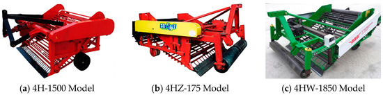
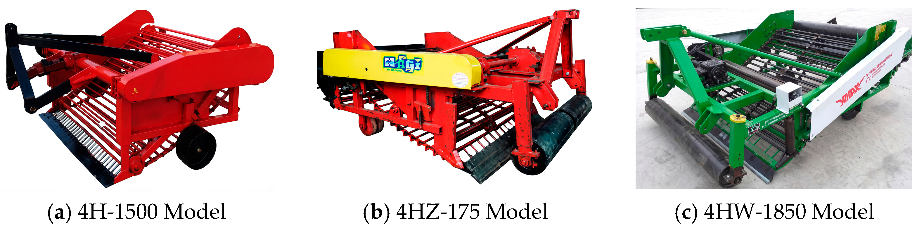
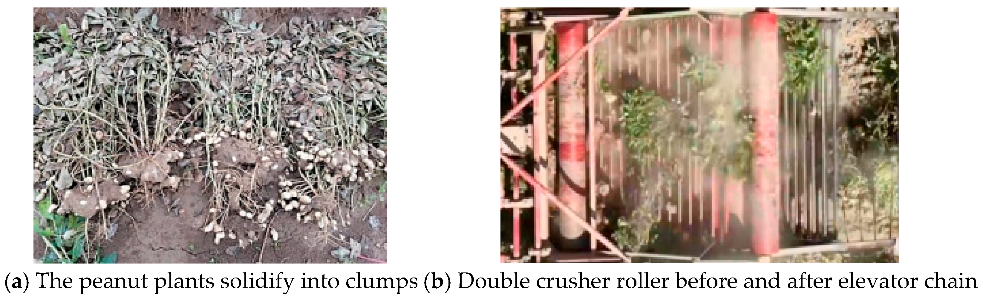
At present, China has developed a wide range of shovel-chain peanut harvesters; however, most models can harvest only two rows simultaneously. Their basic structures and operating principles are generally identical or similar, consisting mainly of a transversely integrated digging shovel, a bar-type conveyor chain (commonly known as the bar chain), a soil-shaking mechanism, a spreading device, a frame, and a transmission system (Figure 1a). The soil-shaking zone is located between the digging shovel and the conveyor chain, where preliminary soil separation occurs. In recent years, continuous improvements have been made to the digging and separation mechanisms of such harvesters [31]. For example, a trailing plant-pressing plate and a depth-limiting roller have been installed in front of the digging shovel to address issues such as excessive digging depth, high operational resistance, uncontrolled free-fall of upright plants after excavation, and disordered plant distribution that impairs soil separation and conveyance efficiency. Additionally, vertically oriented active anti-clogging rollers have been mounted in front of the digging shovel column (Figure 1b,c) to reduce blockages caused by plant and soil accumulation, thereby ensuring smoother material flow and lower resistance. Furthermore, active soil-crushing rollers have been integrated at the front, rear, or both ends of the lifting chain (Figure 1c) to perform secondary soil disintegration and enhance the final separation of soil adhered to the plants. Some advanced models also incorporate dual-stage conveyor chains and multi-step soil-removal mechanisms to further improve separation efficiency. Despite these structural optimizations, persistent issues such as clogging, excessive resistance, and soil adhesion on harvested plants remain unresolved, continuing to restrict the overall operational performance of shovel-chain peanut harvesters under field conditions.
Figure 1.
Typical rod and chain peanut diggers.
2.2. Operational Clogging and Its Causes
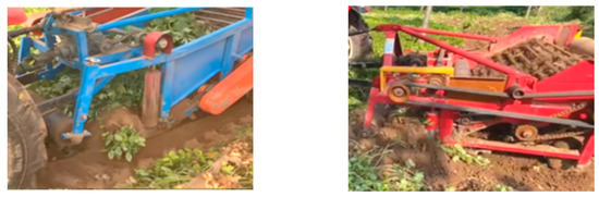
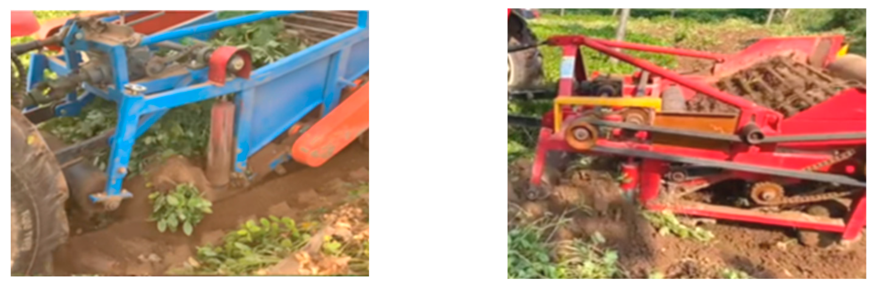
Operational blockage refers to the accumulation of undispersed peanut–soil complex (hereafter referred to as peanut–soil clods) between the digging shovel and the lifting chain during harvesting. This phenomenon occurs when the excavated peanut–soil complex is not effectively fragmented, separated, or conveyed in a timely manner, resulting in congestion within the soil-separation zone (Figure 2). As the blockage develops, the peanut–soil clods gradually expand laterally to cover the entire width of the digging shovel and continue to accumulate. This not only hinders the separation of peanuts from soil—causing increased pod loss and interruptions to continuous conveying—but also generates substantial blockage resistance. The resulting resistance progressively deepens the digging layer, making it more difficult to maintain stable excavation control during operation.
Figure 2.
Typical congestion of shovel-chain peanut digger.
In-depth research reveals that the clogging mechanism of existing shovel-chain peanut harvesters stems from the inability to effectively disintegrate, separate, and remove peanut–soil clods within the soil separation zone. Key contributing factors include the following: First, the limited soil fragmentation capacity of the rotating conveyor chain impedes timely separation of peanut plants from soil. Second, the rotating conveyor chain exhibits insufficient gripping and adhesion force, preventing timely removal of peanut–soil clods and even entire plants from the soil-separation zone. Third, a low speed ratio between the conveyor chain and the harvester’s forward motion results in the gradual accumulation of material, ultimately leading to blockage formation. Fourth, the poor cohesion and continuity between upright peanut plants (including above-ground stalks and below-ground pods) impede the continuous removal of peanut plants from the soil-separation zone.
2.3. The Resistance of the Job Is Heavy and the Causes
Apart from the rolling resistance generated by the harvester’s depth-limiting wheels, the main operational resistance during peanut harvesting consists primarily of digging resistance and clogging resistance. The digging resistance is primarily influenced by factors such as the digging method, shovel geometry, digging width, and soil condition. Conventional shovel-chain peanut harvesters typically employ an integrated transverse digging shovel, which poses several critical challenges. First, the absence of vertical rotary round plow blades causes tearing and lateral disturbance of the soil on both sides of the peanut–soil clods. This not only increases digging resistance but also promotes soil accumulation around the shovel columns, further aggravating resistance. Second, the lack of sliding–cutting motion in the transverse digging process results in elevated cutting resistance and energy consumption. Third, the entire soil layer—including both peanut-bearing topsoil and non-productive subsoil—is excavated indiscriminately during operation, regardless of planting pattern (narrow-row or wide-row flat cultivation), which further increases digging resistance. The clogging resistance, on the other hand, arises from the frictional drag caused by accumulated soil, plant residues, and unseparated peanut–soil clods within the working zone. Its magnitude primarily depends on the degree of blockage, and it escalates sharply as clogging intensifies. In addition, clogging increases the vertical load acting on both the digging shovel and the entire harvester, forcing the blade to penetrate deeper into the soil and, in extreme cases, hindering stable harvesting performance.
2.4. Soil Carryover and Pod Loss: Causes and Mechanisms
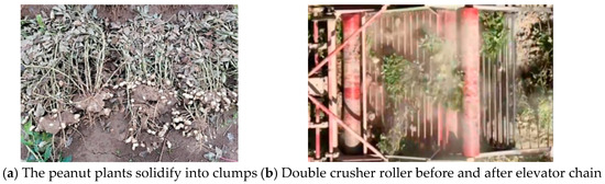
Compared with the clamping-type peanut harvester, which relies on a combined digging–pulling excavation and separation mechanism, conventional shovel-chain peanut harvesters operate based on full-width excavation. Since soil fragmentation rarely occurs during the digging stage, the excavated peanut–soil composite is subsequently crushed and separated by the rotating rod-type conveyor chain. It is therefore evident that the efficiency of soil fragmentation and separation largely depends on the gripping and adhesion forces between the rod-type conveyor chain and the peanut–soil composite. Excessive slippage between the chain and the composite not only reduces soil fragmentation efficiency but also induces a “pod-stripping” phenomenon, in which relative movement between the chain and the peanut plants causes pod detachment and loss. Consequently, operational blockages and soil-covered plants are frequently accompanied by peanut loss. Due to the cohesive interactions among peanut pods, peduncles, and root systems, the excavated peanut–soil complex form high-strength clods that are considerably harder to break apart than ordinary soil (Figure 3a). If these clods are not promptly fragmented within the soil-separation zone, they are unlikely to be further disintegrated by the vibration-based soil-removal mechanism or the active soil-crushing rollers during transport by the lifting chain (Figure 3b). Moreover, these unbroken clods often encapsulate peanut pods, resulting in additional yield loss.
Figure 3.
Soil clods carried by peanut plants after harvest. (Images are original by the authors).
3. Principles and Overall Structure of Resistance-Reducing and Anti-Clogging Excavation–Separation System
3.1. Principles of Excavation and Separation
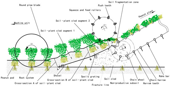
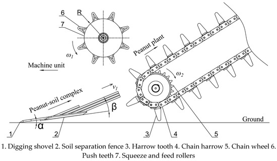
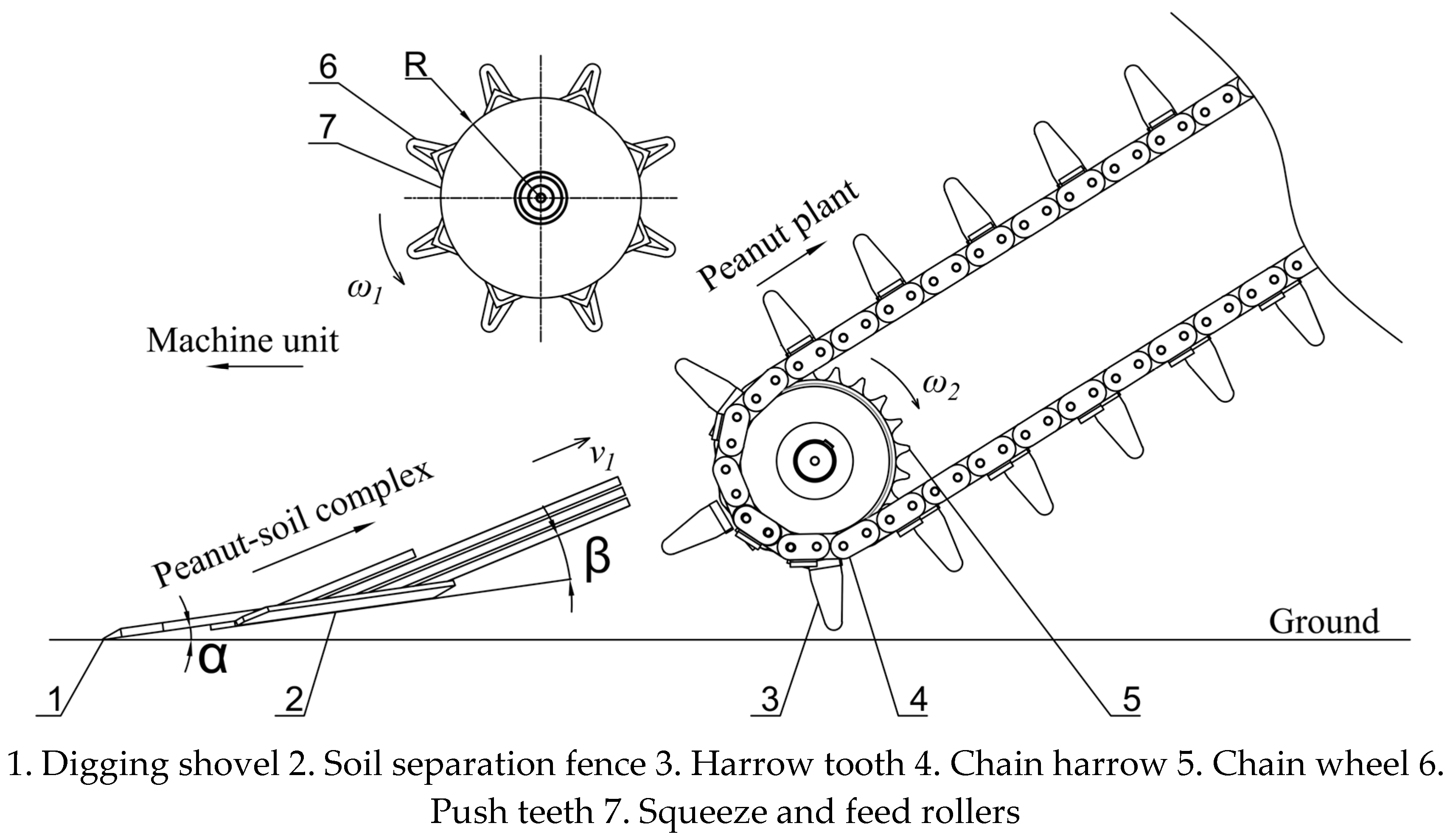
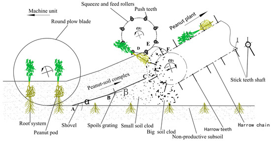
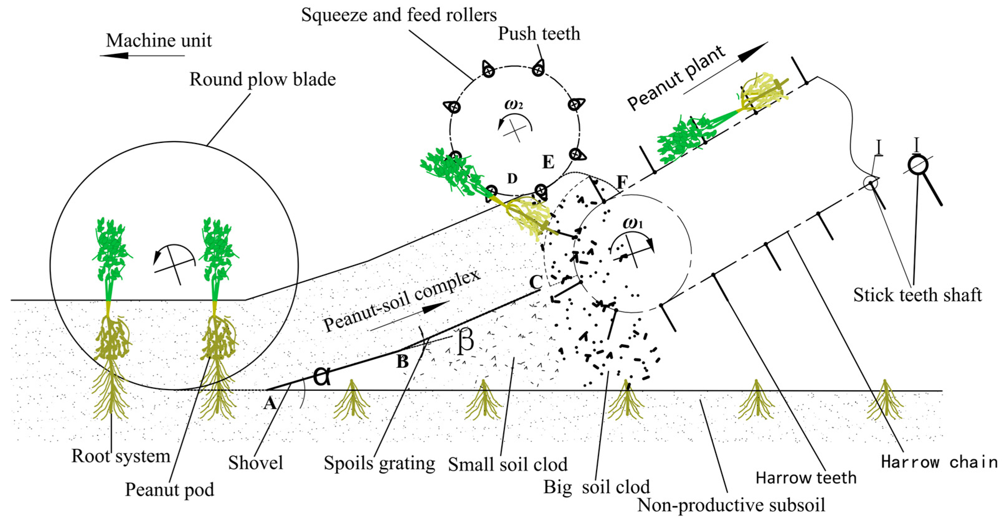
Based on the analysis of the structural characteristics of existing excavation and separation devices, as well as the identified issues of operational clogging, excessive resistance, high soil carryover, and pod loss, this study introduces a resistance-reducing and anti-clogging excavation–separation principle. The proposed principle focuses on achieving progressive soil fragmentation and separation through the coordinated integration of longitudinal and transverse small-section excavation, multi-stage soil disintegration techniques, and a push-and-comb separation mechanism (Figure 4).
Figure 4.
Chain harrow peanut excavation separation principle. (Images are original by the authors).
3.1.1. Principle of Combined Longitudinal–Horizontal Small-Section Excavation
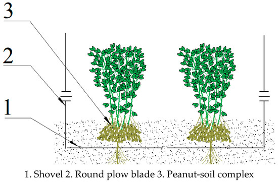
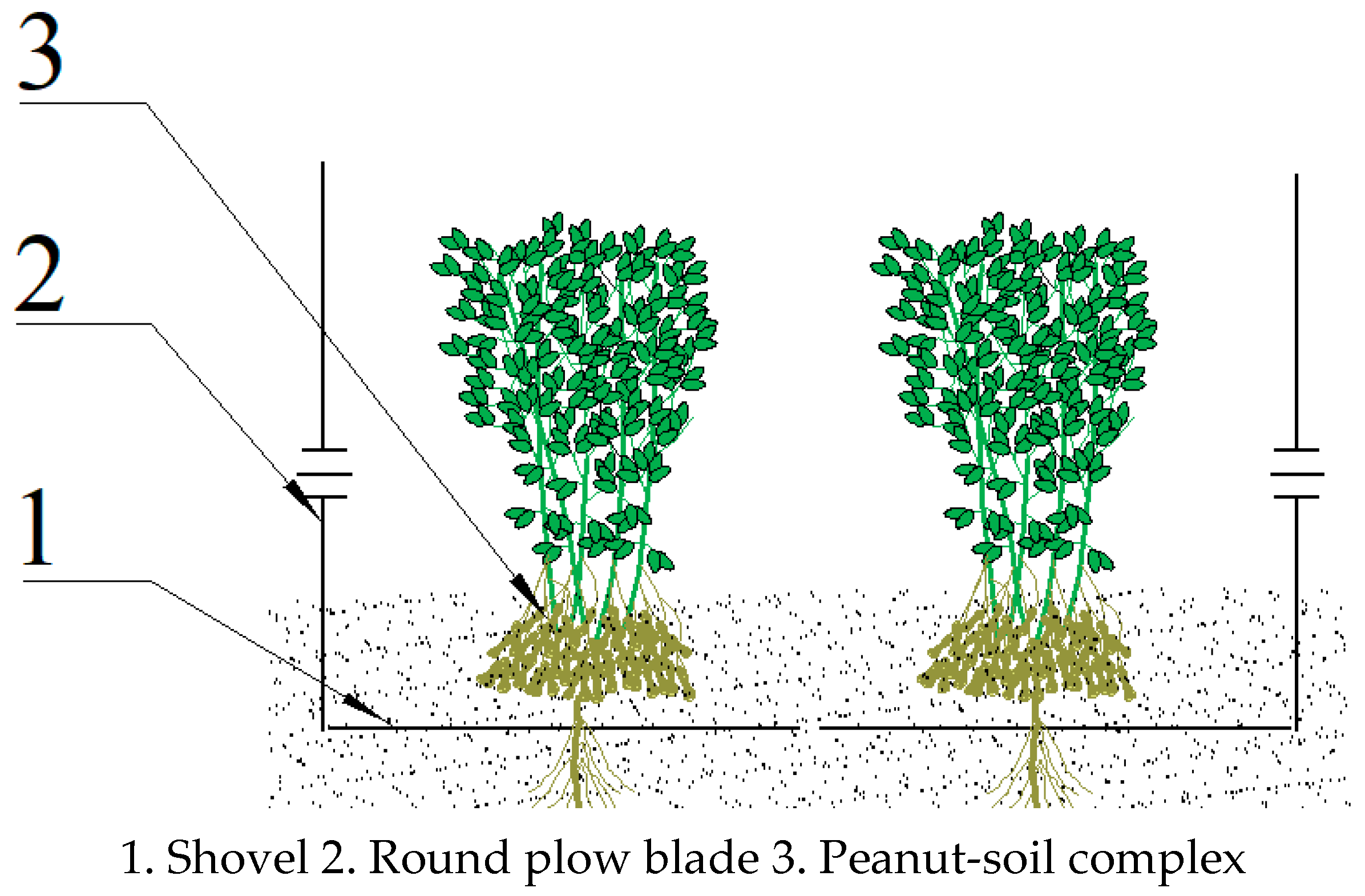
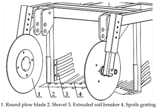
To address the limitations of the conventional integrated transverse horizontal digging shovel, this study adopts a paired configuration comprising inclined digging shovels (1 in Figure 5) and round plow blades (2 in Figure 5). The round plow blades are engineered to sever the soil on both sides of the peanut rows and cross-ridge lateral branches, while the inclined digging shovels cut through the soil beneath the pods and along the main peanut roots. This coordinated cutting action ultimately forms peanut–soil clods (3 in Figure 5) with minimal and uniform cross-sections, which not only reduces excavation resistance but also decreases the mass of peanut–soil clods entering the soil-crushing and separation zone, thereby lowering the separation load. Consequently, a combined longitudinal–horizontal small-section excavation is achieved.
Figure 5.
Schematic diagram of the round plow blade and digging shovel. (Images are original by the authors).
3.1.2. Principle of Multi-Stage Progressive Soil Fragmentation
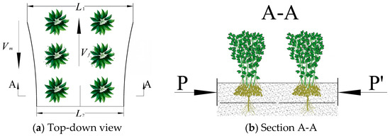
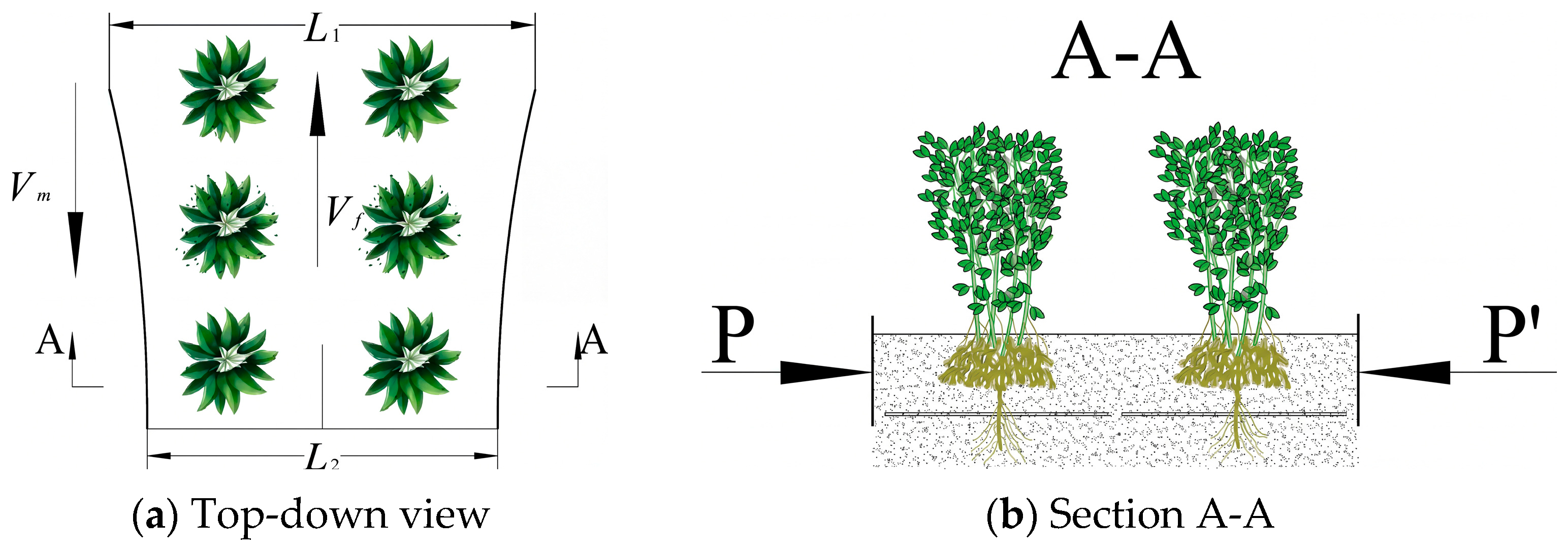
As illustrated in Figure 6a, denotes the forward speed of the machine unit, while represents the speed of the peanut–soil clods. In the A-A section, refers to the digging width and denotes the spacing between the rear ends of the soil-crushing plates. Figure 6b presents a cross-sectional view of the A-A section in Figure 6a, where P indicates the squeezing force exerted by the grid bar on one side of the peanut–soil complex, and P′ represents the squeezing force applied by the grid bar on the other side of the peanut–soil complex. Effective fragmentation of peanut–soil clods is a prerequisite for subsequent separation, conveying, and soil removal, and it is also critical for alleviating operational clogging, particularly under compacted soil conditions. Conventional separation methods that rely solely on the crushing zone are often inadequate for achieving complete disintegration. To address this limitation, this study introduces a multi-stage soil fragmentation approach (Figure 6). In the first stage, a pair of curved compression plates with adjustable spacing are mounted above the digging bucket. These plates guide the peanut–soil clods rearward while applying progressively increasing lateral compression, thereby achieving preliminary crushing and deformation of the clods. In the second stage, an upward-curved soil-separation grid is positioned at the rear of the digging shovel. As the peanut–soil clods pass through section B, they undergo upward bending and cracking (Figure 4), allowing partially loosened soil to fall through the grid gaps, thus completing the second stage of fragmentation. In the third stage, as the clods approach the outlet of the soil-separation grid, a counterclockwise-rotating squeezing and feed roller exerts an upward pressure and axial conveying force (Figure 4). This coordinated action further disintegrates the remaining clods during their rearward and upward movement, thereby completing the final stage of multi-step soil fragmentation.
Figure 6.
Schematic diagram of earth crushing operation of extruded earth crushing board. (Images are original by the authors).
3.1.3. Principle of Combined Conveying–Combing Separation
After excavation and stepwise soil–peanut clod processing, the peanut–soil clods enter the soil–clod separation zone under the combined action of the squeezing and feed roller and the reaction force from the undisturbed soil. Here, they undergo squeezing and feeding by the roller above, while the underside undergoes a combined action of combing, shearing, and stretching from the chain rake tines and rake bars. This process breaks down the peanut–soil clods, separates the plants from the soil, and propels them backward and upward for conveyance. Compared with conventional single-rod or tooth-bar lifting chains, the proposed combined conveying–combing soil-separation mechanism achieves balanced force transmission, bidirectional (upward and downward) operation, and slip-free soil fragmentation, separation, and transport. Consequently, this configuration not only prevents operational clogging but also reduces peanut loss caused by slippage between the lifting chain and peanut–soil clods.
3.2. Overall Structural Configuration
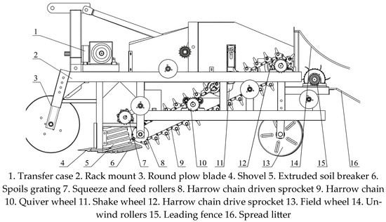
The overall structure of the shovel-chain peanut harvester is illustrated in Figure 7. The machine comprises a digging assembly, a separation assembly, a soil-removal and plant-laying device, a frame, a transmission box, and ground wheels. The digging assembly incorporates a pair of round plow blade, an inclined symmetrical digging shovel, an extrusion-type soil breaker, and a spoil grating. The separation assembly consists of a squeezing and feed roller combined with a rake-chain lifting conveyor. The soil-removal and plant-laying unit integrates a quiver wheel, shake wheel, unwinding rollers, leading fence, and spread litter. The structural configurations and operating principles of the digging and separation assemblies are shown in Figure 8 and Figure 9, respectively.
Figure 7.
Structure diagram of peanut digger with chain harrow. (Images are original by the authors).
Figure 8.
Schematic of structure of digger device. (Images are original by the authors).
Figure 9.
Schematic diagram of separating device with delivery cooperate with sparse selection. (Images are original by the authors).
Working Principle of the Digging and Separating Device: The pair of round plow blades first performs longitudinal soil cutting, slicing through the soil and cross-ridge lateral branches on both sides of the peanut rows. Subsequently, the inclined digging shovels perform horizontal soil cutting, severing the soil and main roots beneath the peanut pods and thereby excavating an integrated peanut–soil clod. An extruded soil breaker, mounted above the digging shovel, guides the excavated clod rearward while applying horizontal compressive crushing to disintegrate the soil. At the rear of the digging shovel, a soil-separation grid is installed at a soil-crushing angle, forcing the peanut–soil clod to bend upward as it moves backward, thereby enhancing soil fragmentation efficiency. When the excavated clods enter the soil-crushing and separation zone—composed of the spoil grating, squeezing and feed roller, and harrow chain—they undergo combined deformation through squeezing, conveying, and combing actions. The counterclockwise rotation of the squeezing and feed roller operates synergistically with the clockwise rotation of the harrow chain, ensuring progressive soil crushing and plant–soil separation. Finally, the separated peanut plants are conveyed diagonally backward by the harrow chain for further soil removal and laying.
4. Design of Key Components
4.1. Design of Excavation Components
4.1.1. Design of Round Plow Blade and Digging Shovel
Based on the peanut planting parameters—including row spacing (narrow-row spacing under flat cultivation), plant height, and pod-bearing range—the maximum row spacing (Z1) was defined as 300 mm, with a horizontal pod distribution diameter (Ø) of 150 mm and a safety clearance (S) of 75 mm between the round plow blade and the peanut pods. Accordingly, the spacing (L) between the two round plow blades was determined using the relationship L ≥ Z1 + Ø + 2S, yielding a minimum spacing of 600 mm. Each round plow blade, with a diameter (D) of 460 mm, was designed with depth-limiting and floating mechanisms to ensure stable digging performance [20,21].
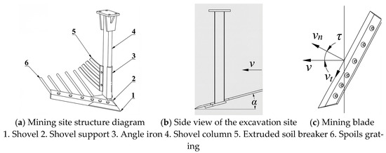
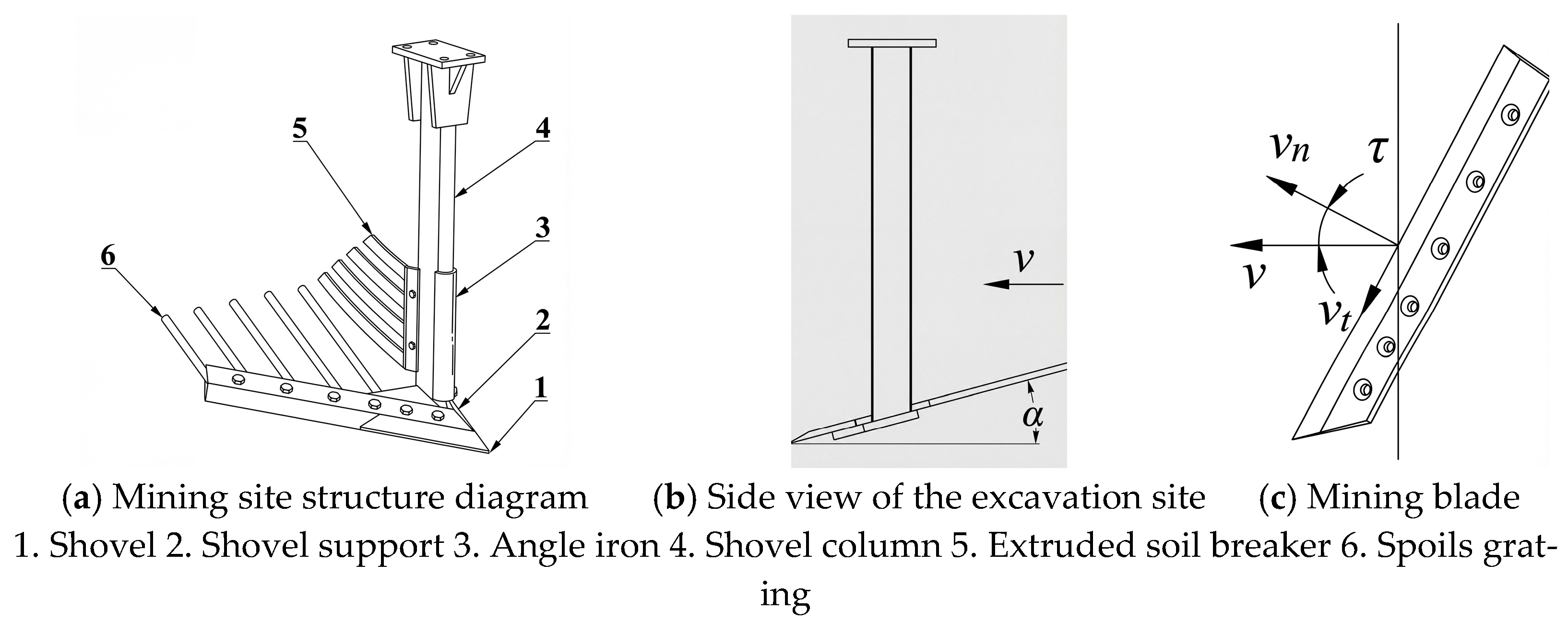
A counter-inclined digging shovel was adopted in the design. Based on relevant design parameters reported in previous studies [20,21,22,23,24,25,26], the slip angle (τ) was set to 35°, the penetration angle (α) to 15°, and the shovel width to 120 mm. According to the required digging width (Figure 10), the length of each digging shovel was determined to be 366 mm. Figure 10a depicts the overall structure of the excavation zone, including 1. shovel, 2. shovel support, 3. angle iron, 4. shovel column, 5. extruded soil breaker, and 6. spoil grating. Figure 10b presents a test diagram of the excavation zone, illustrating the angle of the penetration angle (α) relative to the machine’s forward direction (). Figure 10c shows the cutting edge of the digging blade, annotated with the cutting speed and slip angle (τ).
Figure 10.
Schematic diagram of the combined structure of the excavating shovel. (Images are original by the authors).
4.1.2. Design of Soil-Crushing Plates
Paired curved grille plates and extruded soil breakers are mounted on both sides of the shovel column. The spacing between the grille plates gradually decreases from front to rear, creating a progressive compressive effect on the peanut–soil clods as they are pushed backward, which induces fracture and disintegration under compression (Figure 6). The compression–contraction ratio (i) is defined as
where L1 is the digging width (mm) and L2 is the spacing between the rear ends of the soil-crushing plates (mm).
The determination of the compression ratio must take into account the soil conditions encountered during peanut harvesting. An excessively high compression ratio increases the resistance to peanut–soil clod movement, resulting in potential blockages, whereas an overly low ratio fails to provide sufficient soil-crushing effectiveness. Based on preliminary experimental results and previous research findings [20,21], the feed width (L1) was defined as 600 mm, and the discharge width (L2) was set to 560 mm, yielding a calculated compression ratio (i) of 6.7%.
4.1.3. Design of Soil-Crushing and Separation Grid
As illustrated in Figure 10, the spoil gratings are evenly arranged along the rear section of the digging shovel and inclined upward at an angle β (the soil-crushing angle). This configuration directs the peanut–soil clods rearward while simultaneously performing preliminary soil-crushing and separation functions. Based on the peanut fruiting depth and the thickness of the peanut–soil clods, the spoil grating spacing was defined as 50 mm. At the rear end, a clearance gap of 30 mm was maintained between the spoil grating and the rotating section of the chain harrow, while ensuring adequate ground clearance. This arrangement allows the harrow chain to smoothly engage the peanut–soil clods for secondary fragmentation and separation, keeping the harrow tooth as close as possible to the hard soil layer during rotation without scraping it. Accordingly, the end of the spoil grating was positioned 20 mm closer to the harrow tooth rotation center, resulting in a distance of 137 mm (r + hb + 20 mm) from the rotation center. The clearance above the hard soil layer should therefore equal the harrow tooth rotation radius (r + hb).
Due to the inclined configuration of the digging shovel, the horizontal distance between the front tip and rear edge differs considerably and significantly relative to the chain rake. For the k-th bar, the soil fragmentation angle and bar length are expressed as
In the equation, denotes the horizontal projection distance between the front tip and rear ends of the grid bar along the conveying direction, measured in mm, while represents the height difference between the front tip and rear endpoints of the grid bar, also measured in mm. As decreases from the outer to the inner side, gradually increases while correspondingly decreases. Calculation results indicate that the innermost grid bar has a length of 200 mm with a soil crushing angle of 26°; the outermost grid bar has a length of 410 mm with a soil crushing angle of 11°.
4.2. Design of Harrow Chain
4.2.1. Relative Velocity of Peanut–Soil Clods
The harrow chain serves as a critical component of the soil-crushing, separating, and conveying mechanism in chain-type peanut harvesters. As illustrated in Figure 11, during soil fragmentation and separation, the harrow tooth performs a compound motion relative to the moving peanut–soil clods, tracing an epicycloidal trajectory. To clarify this motion, it is necessary to determine the relative velocity of the peanut–soil clods with respect to the harvester. During continuous harvesting, as the peanut–soil clods move backward and upward along the spoil grating, they ascend vertically to a certain height while exhibiting negligible horizontal displacement. According to the displacement–velocity synthesis theorem, the horizontal component of the relative velocity (Vf) between the peanut–soil clods and the forward velocity (Vm) of the harvester is equal in magnitude but opposite in direction, that is,
Figure 11.
Working principle of separate unit. (Images are original by the authors).
In the equation, Vf represents the relative velocity between the peanut plant and the round plow blade (m·s−1); Vₘ denotes the forward velocity of the harvester unit (m·s−1); α is the penetration angle into the soil (°); and β is the soil fragmentation angle (°).
It is evident that the relative velocity (Vf) between the peanut–soil clod and the machine unit is greater than the forward velocity (Vm) of the harvester. This indicates that the peanut–soil clod undergoes acceleration as it moves along the spoil grating.
As illustrated in Figure 11, A, B, C, D, E, and F represent their sequential positions: Section AB corresponds to peanut plants being excavated by round plow blades and digging shovels to form intact peanut–soil clods, which enter the first stage of soil fragmentation as the machine advances; Section BC denotes the clods moving into the rear soil-crushing and separation grid to initiate the second stage of fragmentation; Point DE is the contact area where the clods interact with the squeeze and feed rollers; Section CF indicates the clods starting the third stage of fragmentation under the counterclockwise pushing of the squeeze and feed rollers and the action of the harrow chain, while being conveyed backward.
4.2.2. Determination of Harrow Chain Speed Ratio
During the soil fragmentation and separation process in peanut harvesting, both the harrow tooth and the rake bars of the harrow chain contribute to soil disintegration and separation. Therefore, for the chain rake to effectively crush, separate, and convey the peanut–soil clods backward, the following condition must be satisfied: the linear velocity of the chain rake (Vl) must be greater than or equal to the relative velocity (Vf) of the peanut–soil clods, that is,
By combining Equations (4) and (5), the ratio of the harrow chain speed (Vl) to the unit forward speed (Vm)—defined as the harrow chain speed ratio (λs)—can be obtained.
The harrow chain speed ratio (λs) is a critical design parameter in peanut harvesters, as it is directly related to the penetration angle (α) of the digging shovel and the soil-crushing angle (β) of the spoil grating. When the harrow chain speed ratio is too low, the harrow chain operates at an insufficient speed, leading to material congestion and clogging. Conversely, when the ratio is too high, the harrow tooth speed becomes excessively fast, resulting in pod loss due to excessive separation forces and broken plant stems during conveying. Therefore, the optimal harrow chain speed ratio (λs) is typically determined according to the following relationship:
4.2.3. Determination of Harrow Tooth Rotational Speed Ratio
As illustrated in Figure 11, when the harrow chain operates along the straight section, both the harrow tooth and the rake bar move at a constant linear velocity (Vl). However, during the C–F curved section, the circumferential velocity (Vc) at the tip of the harrow tooth exceeds the linear velocity (Vl) of the rake bar (i.e., the harrow chain speed). The ratio between these two velocities, defined as the rotational speed ratio of the harrow tooth (λc), can be expressed as
The harrow tooth rotational ratio (λc) is determined by the pitch circle radius of chain wheel (r) and the harrow tooth height (hb), serving as a key design parameter for optimizing both the harrow tooth geometry and the chain wheel rotation radius. A higher rotational ratio (λc) corresponds to a taller harrow tooth, which in turn results in higher separation velocity and greater relative interaction force during operation. When λc remains constant, an increase in chain wheel rotation radius (r) leads to a proportional increase in harrow tooth height (hb), thereby enlarging the overall harrow chain structure and requiring a greater lifting height for the peanut–soil ridges.
4.2.4. Determination of Rake-Tooth Separation Speed Ratio
According to previous research [16], the condition for the harrow tooth to effectively fragment and separate the peanut–soil clods is expressed as follows: when the velocity directions of both are the same, the ratio (λf) between the circumferential velocity (Vc) at the tip of the harrow tooth and the relative velocity (Vf) of the peanut–soil clod—defined as the separation speed ratio—is given by
By combining Equations (4), (5), (8), and (9), the following relationship can be derived:
The harrow tooth separation speed ratio (λf) is a key parameter governing the coordination between peanut separation and conveying speeds. A higher separation speed ratio increases the relative motion between the harrow tooth and the peanut–soil clods, thereby improving soil fragmentation and separation efficiency. However, if the relative velocity becomes excessively high, it may cause peanut pod stems to break, ultimately resulting in yield losses.
It can be observed that when the harrow chain speed (Vl) equals the relative velocity (Vf) between the peanut–soil ridge and the harvester, the harrow tooth separation ratio (λf) becomes equal to the harrow tooth rotational ratio (λc). The height of the harrow tooth (hb) is determined by the pitch circle radius (r) of the chain wheel and the separation ratio (λf). When the separation ratio (λf) is determined to 1.8, the relationship between the harrow tooth height (hb) and the pitch circle radius (r) of the Harrow chain wheel is expressed as follows:
4.2.5. Structural Design of the Chain Rake
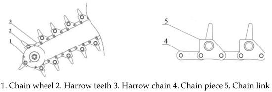
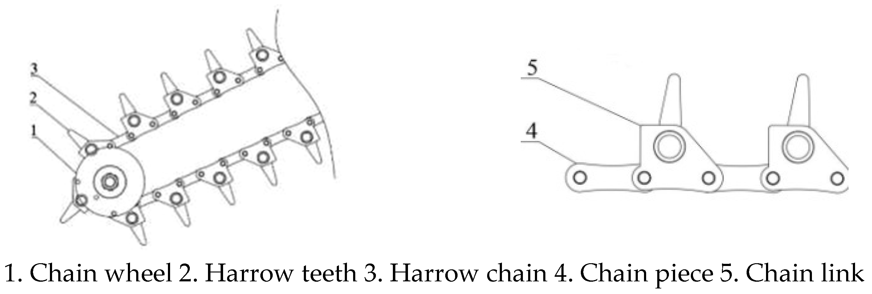
As illustrated in Figure 12, the harrow chain (also referred to as the rake conveyor chain) is an inclined ring-chain mechanism that, together with the squeezing and feeding rollers and the spoil grating, constitutes the soil-separation assembly. This mechanism integrates both soil-separation and plant-conveying functions and is primarily composed of harrow tooth, rake bar, specialized sleeve roller chains, and chain wheel (Figure 12). The harrow teeth are evenly distributed along the rake bars, with the teeth on adjacent bars arranged in a staggered configuration. Both ends of each rake bar are fixed to the chain link of the specialized chain, and the entire harrow-chain engages with chain wheel at both ends for power transmission. The key design parameters of the harrow-chain include the type of harrow-chain, the pitch circle radius (r) of the driven harrow chain, the spacing (S) and length (L) between rake bars, the height of harrow tooth (hb), and the tooth spacing (Sc).
Figure 12.
Structure diagram of separation chain and gear bar. (Images are original by the authors).
- (1)
- Selection of Harrow Chain and Design Determination of Rake Bar Spacing
When selecting the harrow-chain and determining the spacing between rake bars, both the chain pitch and the height of the peanut plants must be considered. Since each rake bar is fixed at both ends to the chain link of a specially designed chain, the rake bar spacing (L) is twice the chain pitch. To ensure efficient soil removal through a combination of conveying and vibration, the rake bar spacing should generally be less than one-fifth of the peanut plant height. Accordingly, a 28A sleeve roller chain with a pitch (P) of 44.5 mm was selected, resulting in a rake bar spacing (S) of 89 mm.
- (2)
- Design Determination of Chain Wheel Pitch Circle Radius and Harrow Tooth Height
Since the harrow chain is driven by the upper drive chain wheel, the chain wheel located at the peanut–soil separation end serves as the driven chain wheel. To simplify the mechanism, a trough-shaped metal wheel was adopted to replace the driven chain wheel, enabling flexible adjustment of both the rotation radius and the harrow tooth height (hb). To minimize the distance between the harrow teeth and the hard soil layer, reduce the penetration angle (α), and decrease excavation resistance. The pitch circle radius (r) of the trough-shaped metal driven chain wheel was determined to be 65 mm. According to Equation (11), the calculated harrow tooth height (hb) is 52 mm.
- (3)
- Design of Rake Bar Length and Harrow Teeth
Considering the widely adopted double-row wide-ridge and wide–narrow-row planting patterns in China’s major peanut-producing regions—where the narrow row spacing is typically 300 mm or less—the rake bar length (L) was determined to be 580 mm. This design was established by considering the peanut plant spacing and the fruiting range, as well as the spacing and contraction characteristics of the round plow blade and extruded soil breaker.
According to previous studies [17,18,19,20,21], to achieve an optimal balance between the harrow tooth soil fragmentation and separation performance and the smooth descent of plants after conveying, the harrow teeth were designed in a narrow triangular shape with a forward inclination angle of approximately 10° and a tooth spacing of 60 mm.
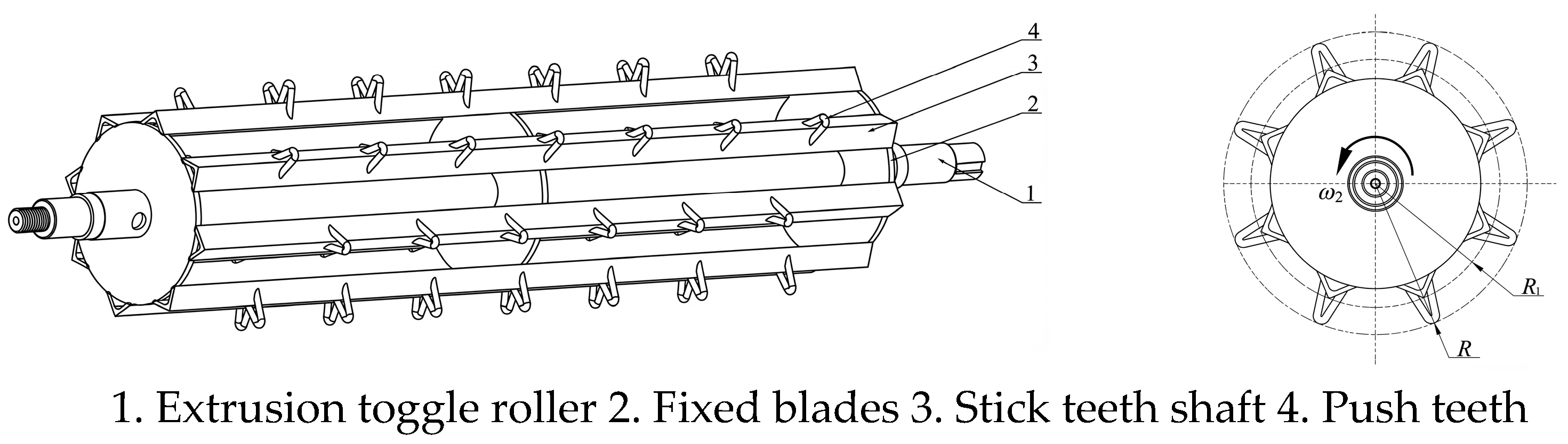
4.3. Design of the Squeeze-Feeding Roller
4.3.1. Structural Form of the Squeeze-Feeding Roller
As illustrated in Figure 13, the squeezing and feed roller is a driven rotating component with a cage-type structure. It is mainly composed of a roller shaft, fixed discs, stick tooth shafts, pulling teeth, and a drive chain wheel. During operation, the roller rotates over the excavated peanut–soil clods, causing the peanut plants to sequentially tilt forward while simultaneously applying squeezing and pulling forces to the clods. To adapt to variations in peanut plant height and soil clod thickness, while also minimizing rolling resistance, preventing plant entanglement, and ensuring adequate pressure and traction, the roller drum diameter is designed to be slightly larger, whereas the tooth height is moderately lower. The extrusion toggle roller is connected to the frame through an elastic floating mechanism, allowing limited movement and self-adjustment. The stick-tooth shaft is fabricated from 30 × 30 mm angle steel and bolted to a fixed plate. Bow-shaped teeth are adopted with an axial spacing of 60 mm, and the teeth in adjacent rows are arranged in a staggered pattern to enhance soil fragmentation and prevent clogging.
Figure 13.
Schematic of squeeze and feed rollers. (Images are original by the authors).
4.3.2. Determination of Transmission Speed Ratio
According to previous studies [16], during the peanut–soil separation process, the harrow teeth undergo both relative translational motion and rotational motion around the shaft axis. The combined trajectory of these motions forms a cycloidal curve, the shape of which is determined by the ratio (λjx) between the linear velocity at the tip of the harrow tooth and the relative velocity of the peanut–soil clods—referred to as the relative harrow tooth speed ratio. For effective squeezing and conveying, when the harrow teeth approach the peanut–soil clods, they must exert a backward-directed force, implying that the epicycloidal path of motion must include a closed loop. The relationship between λjx, the harrow tooth rotational radius (R), the angular velocity (ωj), and the relative velocity (Vf) of the peanut–soil clods is given as follows:
When λjx > 1, the tip of the push teeth exhibits a looping (epicycloidal) motion relative to the moving peanut–soil clods. Under this condition, the velocity at the lowest point of the push teeth tip remains greater than zero and is oriented in the same direction as the relative motion of the peanut–soil clods, thereby generating a backward-propelling effect that assists in moving the clods rearward.
By combining Equations (4) and (12), the ratio (λj) between the tip speed of push teeth and the forward speed (Vm) of the machine unit—defined as the indexing speed ratio—can be expressed as follows:
The transmission ratio (λj) serves as a critical design parameter in the power transmission system of peanut–soil separation equipment.
4.3.3. Determination of Feed Pitch and Number of Feeding-Tooth Rows
The harrow-tooth pitch [16] (Sj) refers to the distance between adjacent harrow teeth that interact with the peanut–soil clods, representing the number of harrow-tooth engagements acting on the clod per unit time or per unit conveying length.
In the equation, Sj represents the feeding pitch (mm); N denotes the number of feeding-tooth rows; and T0 is the time required for one full revolution of the squeeze and feed rollers (s).
By combining Equations (12) and (14),
Equation (15) indicates that the feeding pitch is directly proportional to the tooth rotation radius and inversely proportional to both the number of tooth rows and the feeding speed ratio. A smaller feeding pitch increases the frequency of squeezing and feeding actions applied by the teeth to the peanut–soil clods, thereby enhancing the soil-separation and crushing effects. However, an excessively small feeding pitch also raises the risk of damaging the exposed peanut pod stalks, potentially leading to fruit loss.
Based on peanut plant spacing and height, the feeding-tooth pitch (Sj) was determined to be 100 mm to ensure that each peanut plant undergoes at least one complete compression–removal cycle. Considering the rolling conditions of the squeezing–transfer roller operating over the peanut–soil ridges, the following design parameters were adopted: tooth rotation radius (R) = 140 mm, transfer speed ratio (λj) = 1.3, digging shovel penetration angle (α) = 15°, and average soil-crushing angle (β) = 13°. Under these conditions, the calculated number of tooth rows is 7.66, which was rounded to eight rows for practical implementation.
5. Field Tests of the Excavation–Separation Device
5.1. Experimental Methods
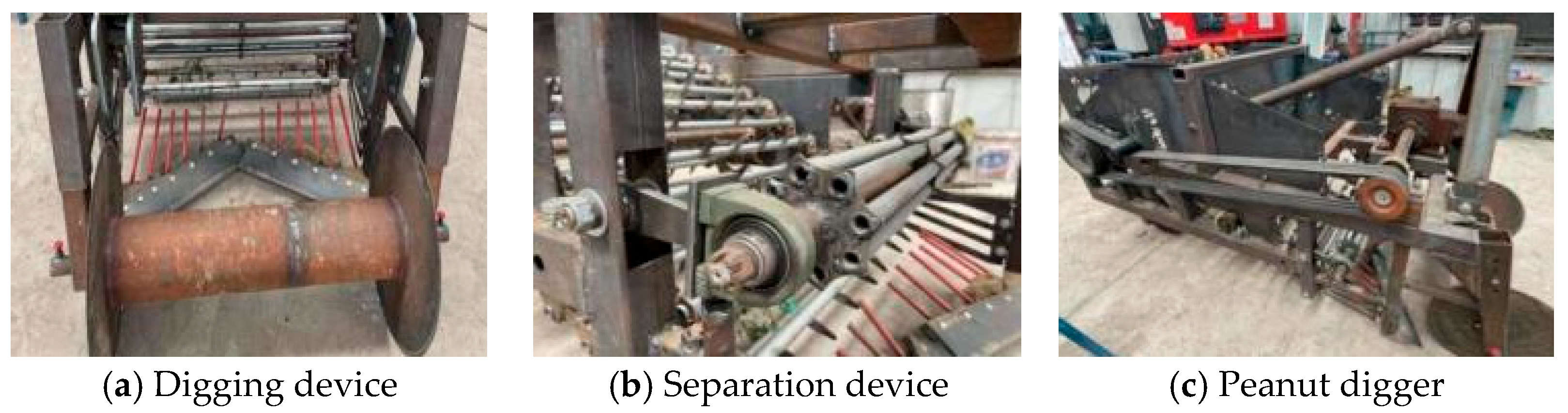
The excavation and separation device, along with the complete prototype, is shown in Figure 14. To evaluate the field performance of the prototype, a Dongfanghong SK404 wheeled tractor was employed to tow the test unit. The testing instruments and equipment included a VICTOR-DM6235P handheld tachometer, a soil moisture meter, an electronic balance, a stopwatch, and a measuring tape.
Figure 14.
Chain harrow peanut digger excavating separation device. (Images are original by the authors).
The field experiment was conducted at the Postgraduate Research Base of Shuangfeng Machinery Manufacturing Co., Ltd., Jilin Agricultural University (Figure 15). The peanut variety used was Yu Hua 22, planted with a ridge spacing of 70 cm, a narrow row spacing of 30 cm, and a plant spacing of 10 cm. The average plant height ranged from 35 to 40 cm, and the peanuts were at the harvest maturity stage without significant signs of senescence. The experimental field was relatively flat, consisting of loose sandy loam soil with a moisture content of 11–15%. In accordance with the Agricultural Industry Standard of the People’s Republic of China—“Quality Requirements for Peanut Harvester Operation” (NY/T 502-2016) [32,33], three subplots were randomly selected within the test area, each measuring 20 m in length. Within each subplot, three sample plots of 2 m length were randomly selected along the longitudinal direction. During operation, the machine speed was maintained at 1.5~1.6 m/s. The following performance indices were measured: ground fruit drop rate (D), buried fruit rate (M), and soil-carrying rate (T). Additionally, observations were made regarding operational blockages and the continuity of plant conveying during the harvesting process.
Figure 15.
Peanut digger test in the field. (Images are original by the authors).
5.2. Experimental Results
The calculation methods for determining the ground fruit drop rate, buried fruit rate, and soil-carrying rate are shown below:
In the equation, D represents the ground fruit drop rate of the peanut harvester, M denotes the buried fruit rate, and T indicates the soil-carrying rate, all expressed as percentages. m1 is the mass of peanut pods scattered on the ground surface within the subplot; m2 is the mass of peanut pods buried in the soil within the subplot; m3 represents the mass of peanut pods remaining on the harvested plants within the subplot; m4 denotes the mass of soil adhering to the peanut plants after harvesting; and m5 represents the total mass of the peanut plants (g).
The average ground fruit drop rate, burial rate, and soil-carrying rate were determined to be 1.13%, 0.95%, and 7.87%, respectively. This soil-carrying rate is lower than the soil content rate range of 8.42% to 23.83% for swing-type peanut harvesters under similar field conditions [34], which reflects the improved soil disintegration effect of the designed multi-stage crushing system and reduces the risk of clogging caused by unbroken soil clods. Throughout the field trials, no operational blockages were observed, and the peanut plants exiting the separation device were smoothly and continuously conveyed by the harrow chain (Table 1).
Table 1.
Results of experiment in the field.
5.3. Analysis of Experimental Results
Field tests showed the prototype operated with low digging resistance. Under the specific conditions (sandy loam, 11–15% moisture content, Yu Hua 22 peanuts), no operational clogging occurred during excavation, separation, or conveyance, with continuous and smooth plant transport by the harrow chain.
As presented in Table 1, the prototype achieved an average ground fruit drop rate of 1.13%, burial rate of 0.95%, and soil-carrying rate of 7.87%, with standard deviations of 0.15%, 0.08%, and 0.89%, respectively, as well as corresponding variances (SD2) of 0.0225, 0.0064, and 0.7921, indicating good data stability. This verifies the effective soil disintegration performance of the designed multi-stage crushing system.
The synergistic design of the combined longitudinal–horizontal small-section excavation device and anti-clogging separation mechanism effectively reduced digging resistance and material accumulation, addressing key issues of traditional harvesters while realizing coordinated optimization of low pod loss and low soil carryover. It should be noted that the anti-clogging performance under other operating conditions requires further validation.
6. Conclusions
- (1)
- To address persistent clogging, high excavation resistance and excessive soil carryover in conventional shovel-chain peanut harvesters, a resistance-reducing and clog-preventing excavation–separation concept was proposed by coupling hybrid longitudinal–horizontal small-section excavation with multi-stage progressive soil fragmentation (compression, bending cracking and secondary fragmentation). In the excavation unit, the optimized key parameters were as follows: round plow blade spacing L = 600 mm and blade diameter D = 460 mm; digging shovel slip angle τ = 35°, penetration angle α = 15°, shovel width 120 mm and shovel length 366 mm; spoil -grating spacing 50 mm and a clearance gap of 30 mm between the spoil grating and the harrow-chain rotation zone.
- (2)
- Compared with commonly used shovel-chain equipment that relies on an integrated transverse digging shovel and a bar-type lifting chain, the proposed separation unit replaces single-bar lifting with a squeeze-feeding roller and a slip-free ring harrow chain, enabling forced feeding and non-slip separation to alleviate clogging and enhance soil removal. The optimized numerical parameters include the following: compression ratio i = 6.7% (feed width L1 = 600 mm, discharge width L2 = 560 mm); harrow-chain separation speed ratio λf = 1.8 with driven wheel pitch radius r = 65 mm and harrow tooth height hb = 52 mm; chain pitch P = 44.5 mm (rake-bar spacing S = 89 mm), rake-bar length 580 mm, harrow-tooth spacing 60 mm and forward inclination angle about 10°; squeeze-feeding roller tooth rotation radius R = 140 mm, transfer speed ratio λj = 1.3, feeding pitch Sj = 100 mm and tooth rows N = 8.
- (3)
- Based on motion and morphological analysis of peanut–soil clods and kinematic–mechanical analysis of key components, the coupling relationship between the clod relative velocity and the machine forward speed was established, providing a quantitative basis for parameter matching and stable coordination between excavation, fragmentation and separation.
- (4)
- Field tests under sandy loam conditions (soil moisture content 11–15% and forward speed 1.5–1.6 km h−1) showed an average ground fruit drop rate of 1.13%, buried fruit rate of 0.95% and soil-carrying rate of 7.87%. No operational clogging occurred and plants were conveyed smoothly, demonstrating that the optimized prototype meets the agronomic and performance requirements for efficient peanut harvesting.
Author Contributions
Conceptualization, J.Y., D.L., W.Y. and Y.C.; Data curation, J.Y., W.Y., L.G. and H.L. (Hongtao Liu); Formal analysis, W.Y., H.L. (Hongtao Liu) and D.H.; Funding acquisition, L.G. and D.H.; Investigation, J.Y.; Methodology, J.Y. and D.L.; Project administration, W.Y., L.G., H.L. (Hui Liu), Z.S., J.F., Y.C. and D.H.; Resources, J.Y., D.L. and Z.S.; Software, J.Y., D.L. and Z.S.; Supervision, J.Y., J.F. and H.L.; Validation, Z.S., J.F., H.L. (Hui Liu), Y.C. and D.H.; Visualization, J.Y., J.F. and H.L. (Hongtao Liu); Writing—original draft, J.Y. and D.L.; Writing—review and editing, J.Y. and D.L. All authors have read and agreed to the published version of the manuscript.
Funding
This research was funded by the “Natural Science Foundation of Jilin Province” (20230101219JC) and “National Key Research and Development Program of China” (grant number 2023YFD1500404).
Institutional Review Board Statement
Not applicable.
Informed Consent Statement
Not applicable.
Data Availability Statement
The original contributions presented in this study are included in the article. Further inquiries can be directed to the corresponding author.
Conflicts of Interest
The authors declare no conflicts of interest.
References
- Liao, B. Analysis of Current Situation and Development Potential of Peanut Production in China. Chin. J. Oil Crop Sci. 2020, 42, 161–166. [Google Scholar] [CrossRef]
- Zhang, C.; Kang, J.; Zhang, N.; Li, W.; Tiu, S. Research Status and Development Analysis of Key Technologies for Peanut Planting Mechanization. Agric. Equip. Veh. Eng. 2019, 57, 27–34. [Google Scholar]
- Shen, H.; Luo, W.; Wu, F.; Gu, F.; Yang, H.; Hu, Z. Research Progress on Mechanized Harvesting Equipment and Technology for Peanuts. Trans. Chin. Soc. Agric. Mach. 2024, 55, 21–38. [Google Scholar] [CrossRef]
- Yan, X. Developing peanut mechanization must take the road of independent innovation. China Agric. Mach. Superv. 2022, 44–46. [Google Scholar]
- Sun, Y.; Shang, S.; Wang, D.; Yang, R.; Wang, Y.; Wang, B. Current situation and technical characteristics of peanut harvesting machinery in the United States. J. Agric. Mech. Res. 2014, 36, 7–11. [Google Scholar] [CrossRef]
- Wang, Q.; Yu, Z.; Zhang, Y.; Li, J.; Peng, B.; Wang, B.; Hu, Z. Experimental Study of a 4HLB-4 Half-Feed Four-Row Peanut Combine Harvester. Agronomy 2022, 12, 3094. [Google Scholar] [CrossRef] [Scilit]
- Mooney, B. Peanut Digger and Shaker. U.S. Patent 2384763, 11 September 1945. [Google Scholar]
- Zerbato, C.; Silva, V.F.A.; Torres, L.S.; Silva, R.P.; Furlani, C.E.A. Peanut mechanized digging regarding to plant population and soil water level. Rev. Bras. De Eng. Agric. E Ambient. 2014, 18, 459–465. [Google Scholar] [CrossRef] [Scilit]
- Wang, L.; Wei, J.; Li, Y.; Wang, Q.; Han, P.; Guan, Q.; Liu, Z. Development of peanut’s whole course mechanization in our country and the application in Xinjiang. Chinese Agric. Sci. Bull. 2014, 30, 161–168. [Google Scholar] [CrossRef]
- Le, L. Scientific research must be politically directed. Chin. Agric. Sci. 1960, 52–54. [Google Scholar]
- Chen, S.; Li, Y.; Sun, X. Dynamic Performance Analysis and Experiment on Peanut Digging Shovel. Trans. Chin. Soc. Agric. Mach. 2005, 65–69. [Google Scholar] [CrossRef]
- Shang, S. Study on Design Principle and Testing for Swing Type Peanut Harvesting Installation. Ph.D. Thesis, Shenyang Agricultural University, Shenyang, China, 2005. [Google Scholar]
- Wang, D. Study on Key Mechanism of Peanut Combine Harvester. Ph.D. Thesis, Shenyang Agricultural University, Shenyang, China, 2013. [Google Scholar]
- Yang, R.; Xu, Y.; Liang, J.; Shang, S.; Sun, T.; Li, G. Tests and analyses of mechanical properties of peanut root, stem and nut node in mechanical harvest. Trans. Chin. Soc. Agric. Eng. 2009, 25, 127–132. [Google Scholar] [CrossRef]
- Hu, Z.; Peng, B.; Yin, W.; Wang, H.; Ji, F.; Xie, H. Desing and experiment on multifunctional root-tuber crops combine. Trans. Chin. Soc. Agric. Mach. 2008, 39, 58–61. [Google Scholar]
- Hu, Z.; Peng, B.; Xie, H.; Tian, L.; Wang, H.; Wu, F. Design and experiment of chain peanut harvester. J. Agric. Mach. 2008, 220–222. [Google Scholar]
- Hu, Z.; Chen, Y.; Wang, H.; Zhang, H.; Xie, H.; Tian, L. Design and experimental research on vibrating type peanut harvester. Trans. Chin. Soc. Agric. Eng. 2008, 24, 114–117. [Google Scholar] [CrossRef]
- Gao, L.; Liang, G.; Cai, Y.; Feng, W.; Yang, Y.; Liu, J.; Yang, J. Design and experiment on pickup device of bunch peanut with shovel teeth and double-cylinders. Trans. Chin. Soc. Agric. Eng. 2024, 40, 13–22. [Google Scholar] [CrossRef]
- Gao, L.; Wang, D.; Dong, H.; Kong, P.; Li, H.; Liu, Z. Design and Test of Turnover Laying Device of Peanut Harvester. J. Shenyang Agric. Univ. 2016, 47, 57–63. [Google Scholar]
- Wang, D. Experimental Study on the Overturn and Laying Device of Shovel Chain Type Peanut Harvester. Master’s Thesis, Shenyang Agricultural University, Shenyang, China, 2016. [Google Scholar]
- Kong, P. Experiment on Small Scale Shove-roller Type Peanut Harvester. Master’s Thesis, Shenyang Agricultural University, Shenyang, China, 2016. [Google Scholar]
- Zhou, Q. Design of Shovel-Chain Type Low-Laying Peanut Harvester and Performance Test of Conveying and Laying. Master’s Thesis, Jilin Agricultural University, Changchun, China, 2022. [Google Scholar] [CrossRef]
- Cai, Y. Design and Test on Key Components of Shovel Chain Peanut Digger. Master’s Thesis, Jilin Agricultural University, Changchun, China, 2024. [Google Scholar] [CrossRef]
- Gao, L.; Cai, Y.; Zhou, Q.; Liu, J.; Liang, G.; Ren, X.; Yuan, J.; Feng, W.; Yang, Y.; Yang, P.; et al. A Shovel Chain Peanut Harvester. China Patent CN115769725A, 12 April 2024. [Google Scholar]
- Gao, L.; Liang, G.; Zhou, Q.; Yang, Y.; Feng, W.; Yuan, J.; Cai, Y.; Liu, J.; Wang, J.; Wang, G.; et al. A Fixed-Moving Tooth Combined Step-by-Step Peanut Picking Device. China Patent CN114557185A, 9 April 2024. [Google Scholar]
- Gao, L.; Zhou, Q.; Liang, G.; Yang, Y.; Feng, W.; Yuan, J.; Cai, Y.; Liu, J.; Xu, S.; Zhao, Q.; et al. A Clamping Peanut Harvester. China Patent CN114342637A, 31 October 2023. [Google Scholar]
- Li, H.; Shang, S.; Wang, D.; He, X.; Yue, D.; Guo, P.; Xu, N.; Xia, C. Design and Simulation Analysis of Digging Shovel for Six-row Monopoly Crop (Flat Crop) Peanut Harvester. J. Agric. Mech. Res. 2023, 45, 107–112. [Google Scholar]
- Zhao, Z.; Gao, Q.; Lv, J. Development status of potato soil separation device for potato harvester. China Potato 2024, 38, 236–244. [Google Scholar] [CrossRef]
- Zhang, Q. Design and Research of Potato Soil Separation Device for Potato Harvester. Master’s Thesis, Yunnan Agricultural University, Kunming, China, 2023. [Google Scholar] [CrossRef]
- Niu, C.; Xing, Y.; Yan, C.; Tan, H.; Ma, S.; Xu, L. Shovel type farmland stone Simulation and Experiment of Pick-up Collector. J. China Agric. Univ. 2022, 27, 221–233. [Google Scholar]
- Yang, R.; Shang, S. Design and test of multifunctional curved-surface shovel in digging harvest. Trans. Chin. Soc. Agric. Eng. 2012, 28, 47–52. [Google Scholar] [CrossRef]
- NY/T 502-2016; Ministry of Agriculture of the People’s Republic of China. Peanut Harvesting Machinery Operation Quality. China Standard Press: Beijing, China, 2016.
- NY/T 2204-2012; Ministry of Agriculture of the People’s Republic of China. Peanut Harvest Machinery Quality Evaluation Technical Specification. The Communist Party of China Agricultural Press: Beijing, China, 2013.
- Wang, F.; Liu, X.; Liang, J.; Shang, S.; Wang, Z. Experimental Study on the Performance of Swing Type Peanut Harvester. J. Agric. Mech. Res. 2009, 31, 164–168. [Google Scholar] [CrossRef]

Disclaimer/Publisher’s Note: The statements, opinions and data contained in all publications are solely those of the individual author(s) and contributor(s) and not of MDPI and/or the editor(s). MDPI and/or the editor(s) disclaim responsibility for any injury to people or property resulting from any ideas, methods, instructions or products referred to in the content. |
© 2026 by the authors. Licensee MDPI, Basel, Switzerland. This article is an open access article distributed under the terms and conditions of the Creative Commons Attribution (CC BY) license.