


Abstract
Digital reconstruction and augmented reality are increasingly used in industrial heritage, but relatively few studies document the complete and reproducible process from historical data acquisition to the final AR-ready model for public exhibition. This study proposes a transferable workflow for the digital reconstruction and dissemination of historically significant machinery in publicly accessible virtual museums. The methodology was applied to the reconstruction of the steam engines developed by Thomas Newcomen in 1712, together with the improvements subsequently patented by James Watt in 1769. Historical drawings, patents, technical descriptions and dimensional references were analysed to reconstruct the machines as hierarchically organised CAD assemblies. Reconstruction decisions were documented through a traceability matrix distinguishing documented, inferred, reconstructed and simplified elements. The resulting models were validated by checking dimensional consistency, component positioning, mechanical interfaces and functional coherence with the historical sources, while their kinematic behaviour was additionally verified using a motion study. The validated assemblies were subsequently converted and prepared for web-based augmented-reality visualisation. The proposed workflow constitutes a replicable methodology to the reconstruction and interpretation of other historical machines, particularly when surviving physical evidence and technical documentation are incomplete or dispersed. Given the incomplete nature of the surviving historical evidence, the resulting models should be interpreted as technically coherent and traceable reconstructions rather than exact reproductions of the original machines.
1. Introduction
The introduction of the steam engine into the mining sector represented a decisive turning point in the history of technology and industrialisation. By the late XVII and early XVIII centuries, extractive activities were constrained by major technical limitations, particularly those associated with draining the water that accumulated inside mines [1]. Before steam power was adopted as a driving force, this task was performed using drainage galleries, manual extraction systems, animal-powered mechanisms, waterwheels and various hydraulic pumping devices [2]. Although these solutions allowed relatively shallow deposits to be exploited, their capacity proved insufficient to remove large volumes of water as mining operations reached greater depths [3]. The introduction of steam-powered pumping machinery progressively overcame this limitation, facilitating access to mineral resources that had previously been inaccessible [4].
The steam engine cannot be regarded as the isolated achievement of a single inventor, but rather as the outcome of a prolonged process of technological accumulation in which scientific knowledge, construction advances and empirical improvements converged over several centuries [5]. From early devices based on steam expansion, such as the aeolipile attributed to Hero of Alexandria, to the contributions of Jerónimo de Ayanz, Denis Papin, and Thomas Savery, different inventors helped establish the physical principles and technical solutions that subsequently enabled its industrial development [6]. However, regarding its effective application in mining, the contributions of Thomas Newcomen and James Watt are particularly significant [7,8].
Aware of the practical limitations of earlier systems, Newcomen combined the principles of steam condensation and atmospheric pressure with a beam mechanism connected to pumps located within mine shafts [9]. In 1712, he constructed one of the first atmospheric engines capable of operating with sufficient reliability in mine-drainage applications [10]. In this design, steam introduced into the cylinder was condensed by injecting water, thereby creating a partial vacuum. Atmospheric pressure then acted on the piston, producing the reciprocating movement of the beam that drove the pump rods. The adaptation of this system to the materials, technical knowledge and manufacturing processes available at the time was fundamental to its widespread adoption and transformed the Newcomen engine into a practical solution for draining deep mines [11]. Newcomen did not obtain a separate patent for his atmospheric engine because Savery’s broad patent of 1698, extended by the English Parliament until 1733, was still in force. Consequently, the first Newcomen engines were constructed and operated under Savery’s patent rights [12].
Although the Newcomen engine effectively addressed the pumping problem, it consumed large amounts of fuel because the cylinder was repeatedly heated and cooled during each operating cycle. A decisive step toward overcoming this limitation occurred in 1763, when James Watt was asked to repair a working model of a Newcomen engine owned by the University of Glasgow. At that time, Watt had also attended the lectures of Joseph Black, whose studies on latent heat and calorimetry profoundly influenced his understanding of heat transfer. While attempting to restore the model to operation, Watt recognized that much of the engine’s inefficiency resulted from the repeated heating and cooling of the cylinder [13]. From 1765 onwards, James Watt developed a series of modifications aimed at reducing these thermal losses. The most significant was the introduction of a separate condenser, patented in 1769, which allowed the main cylinder to remain hot while condensation took place in a separate and continuously cooled chamber [14]. This solution substantially reduced steam and fuel consumption. Watt subsequently introduced further improvements, including thermal insulation of the cylinder, double-acting operation, expansive use of steam, mechanisms for converting reciprocating motion into continuous rotary motion and speed-regulation systems. Taken together, these innovations extended the applications of the steam engine beyond mine pumping and transformed it into a source of power suitable for factories, workshops and transport systems [15].
The Newcomen and Watt engines therefore constitute essential examples of industrial and mining heritage. Their significance lies not only in their age or status as technological artefacts but also in the knowledge they embody regarding materials, manufacturing processes, construction solutions, transmission mechanisms and the forms of productive organisation characteristic of the First Industrial Revolution [16]. They also illustrate how technical innovation often emerges through the gradual modification and optimisation of existing systems rather than through a complete break with previously established principles [17].
Nevertheless, the preservation and dissemination of this heritage involve considerable difficulties. Many of these machines have disappeared, survive only partially or have undergone modifications that differ from their original configurations. The remaining examples are scarce and, because of their dimensions, state of preservation, or safety requirements, cannot always be operated or internally examined by visitors [18]. Furthermore, the information needed to understand them is often dispersed across historical drawings, engravings, patents, technical descriptions, photographs, physical models and subsequent studies [19]. This fragmentation of the available evidence complicates both the reconstruction of their original configurations and the comprehensive interpretation of their components and operating cycles.
Within this context, three-dimensional documentation and modelling techniques offer new opportunities for the research, preservation and interpretation of industrial heritage [20]. Digital models make it possible to integrate information from heterogeneous sources, represent missing or inaccessible components and analyse the geometric and kinematic relationships between the different parts of a machine. They also enable the generation of sectional views, exploded assemblies, animations and operating sequences that would be difficult to obtain through the direct observation of a physical artefact [21]. Digital reconstruction can therefore become a research instrument for examining the machine itself, rather than merely a visual representation intended for exhibition [22].
However, a heritage-related digital reconstruction should not be assessed solely on the basis of its graphic realism. Its scientific validity also depends on the identification and evaluation of the sources used, the traceability of the decisions made during the modelling process and the distinction between documented, inferred and simplified elements [23]. The London Charter establishes that the sources used in computer-based heritage visualisation should be systematically identified and evaluated and the resulting documentation should allow the methods and outcomes to be understood and assessed [24]. These principles also emphasise the need to consider the sustainability, accessibility and future reuse of digital resources.
Augmented reality and virtual reality further expand the potential uses of these models [25]. Whereas virtual reality places the user within a completely digital environment, augmented reality superimposes digital models and information onto the physical world [26]. Both technologies are increasingly used in museums and heritage sites to reconstruct lost assets, contextualise objects, present supplementary information and allow elements that cannot be directly manipulated to be explored. Recent literature identifies three-dimensional reconstruction, virtual museums, education, user experience and heritage interpretation among the principal fields in which augmented reality is applied to cultural heritage [27]. These environments are particularly useful in the context of industrial heritage because of the complexity of the machinery and processes represented. Interactive visualisation allows the internal mechanisms to be examined, individual components to be isolated, the scale of representation to be modified and operating cycles to be displayed sequentially [28]. It can also reduce the need to manipulate fragile original artefacts and complement physical exhibitions with content that facilitates the interpretation of their mechanical architecture [29].
Despite these advances, many digital reconstructions of historical machinery continue to be developed as individual case studies. The principal outcome is often a three-dimensional model or a specific visualisation application, while the procedure followed to transform incomplete historical documentation into a functional digital assembly is not described in sufficient detail to permit its reproduction or adaptation to other heritage assets [30]. Similarly, source evaluation, geometric reconstruction, kinematic and functional analysis and the subsequent adaptation of models to interactive environments are not always integrated within a single methodological workflow [31]. Recent research on the digitisation of historical machinery has therefore highlighted the need to extend individual experiences through systematic procedures capable of supporting the creation of standardised repositories and virtual museums of industrial heritage [32].
To address this research gap, the present study develops a traceable and reproducible methodology for the digital reconstruction, functional analysis and interactive dissemination of historical machinery. The methodology combines the examination of historical and technical sources, the application of simple reverse-engineering procedures, three-dimensional modelling of components, the analysis of operating cycles and the adaptation of the resulting models to an augmented reality environment. Although it is specifically applied to the Newcomen (1712, without patent) and Watt (first model patented in 1769) steam engines, the procedure is conceived as a transferable framework for other historical machines, particularly when surviving examples, original drawings, or technical documentation are incomplete or dispersed.
The resulting models are first used to identify and compare the main components, mechanical relationships and operating principles of both engines. This analysis makes it possible to examine the technological evolution from Newcomen’s design to Watt’s developments and to assess whether the latter represented a conceptual rupture or, alternatively, a progressive optimisation of previously established atmospheric and mechanical principles. Secondly, the models are optimised and incorporated into a web-based augmented reality environment, through which they can be visualised at different scales and explored interactively. Their integration into the Virtual Museum of the School of Industrial Engineering at the University of Malaga provides a resource for preserving and disseminating the technical knowledge associated with these fundamental examples of industrial and mining heritage.
Previous studies have addressed several of the methodological challenges involved in digital heritage reconstruction, although generally with different objectives and scopes. Gherardini and Sirocchi [20], for example, proposed a systematic procedure for integrating and cross-validating heterogeneous 2D and 3D evidence in the reconstruction of a lost heritage artefact, whereas Horkai [23] focused on documenting uncertainty and interpretative decisions through structured paradata in archive-based reconstruction. In the field of historical machinery, previous studies have demonstrated the value of CAD modelling for digitally preserving and interpreting individual machines [21,30] and of computer-aided engineering for analysing the mechanical behaviour of reconstructed historical designs [22]. Other contributions have primarily addressed augmented and virtual reality as tools for heritage visualisation, interaction and museum dissemination [25,26,27,28,29,30], or the organisation and reuse of three-dimensional heritage resources through digital repositories [32].
The present methodology builds upon these established approaches but differs in its engineering-oriented integration of the complete reconstruction chain. Specifically, it formalises the decomposition of a historical machine into individually identified and coded parts, their organisation into functional subassemblies and complete assemblies, the verification of mechanical and kinematic coherence through CAD-based motion studies and the subsequent technical transformation of the validated assembly into an AR-ready model.
To provide a concise overview of the methodological positioning of the present study, Table 1 compares representative previous approaches with the proposed workflow in terms of documentary-source integration, three-dimensional reconstruction, hierarchical organisation of parts and subassemblies, functional or kinematic verification, traceability, and deployment in immersive or augmented-reality environments.
Table 1.
Comparison of representative digital heritage reconstruction approaches and the methodological scope of the present study.
As shown in Table 1, the individual techniques employed in this study are not themselves novel; Rather than introducing a new individual digital technique, the contribution is the definition of a transferable source-to-assembly-to-motion-to-AR procedure in which documentary interpretation, hierarchical mechanical reconstruction, functional verification and interactive deployment are treated as consecutive and explicitly documented stages of the same workflow. The proposed methodology is therefore intended to support the creation of scientifically documented, reusable digital resources that can be applied to other elements of technological heritage.
2. Methodology
The strategy adopted for the digital reconstruction of an industrial heritage asset depends primarily on whether the original object has survived and whether it is physically accessible. When the asset is preserved and can be examined directly, reality-based reverse-engineering techniques may be applied, including conventional dimensional measurement, close-range photogrammetry, structured-light scanning and terrestrial or portable laser scanning [33]. These techniques generate point clouds, polygonal meshes and metric records of the asset, which can subsequently be used as the basis for three-dimensional or parametric CAD modelling. Depending on the characteristics, dimensions, accessibility and required accuracy of the asset, photogrammetric and range-based techniques may be used independently or combined within a hybrid acquisition workflow [34].
Conversely, when the original asset has disappeared, survives only partially or cannot be accessed, the reconstruction must be based primarily on documentary evidence. Historical drawings, engravings, patents, technical manuals, photographs, written descriptions and comparisons with analogous machines may then be used to identify the components, establish their functional relationships, and infer the original geometry [35]. When at least one reliable dimension is known, basic reverse-engineering and proportional-scaling procedures can be applied to establish the scale of the documentary sources and estimate the remaining dimensions. The resulting geometry should subsequently be checked against mechanical, assembly and functional constraints, while all inferred, assumed or simplified elements should be explicitly documented [36]. The present study addresses the latter methodological scenario, in which the original assets are either no longer extant or are not sufficiently accessible for direct geometric acquisition.
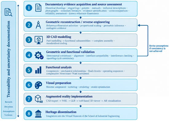
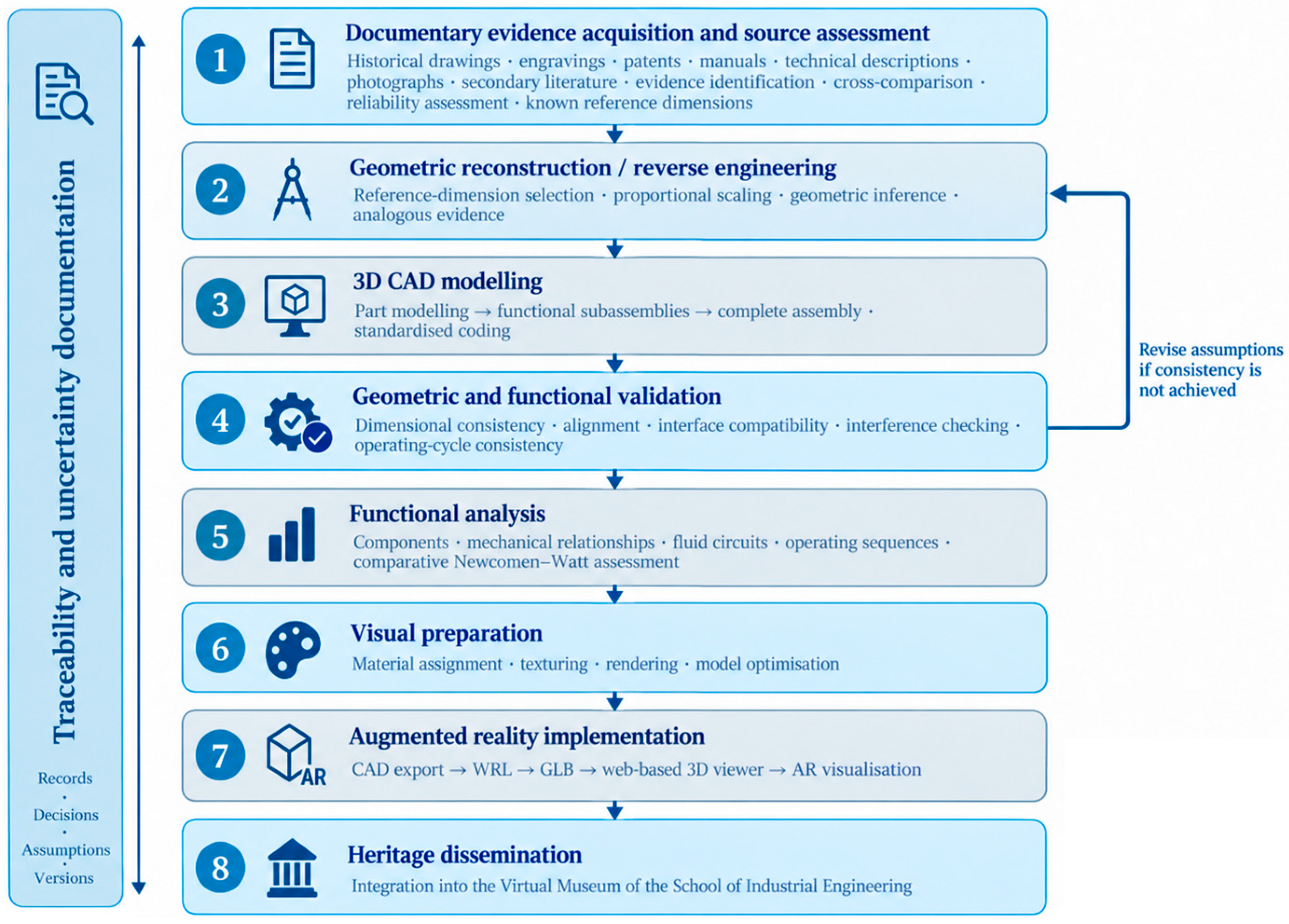
Figure 1 summarises the methodological workflow followed to achieve the objectives of this study.
Figure 1.
Methodological workflow.
The first phase consisted of the systematic collection and critical examination of documentary evidence concerning the geometry, dimensions, construction materials and operating principles of the machines analysed. Historical drawings, technical descriptions, specialised publications and other available sources were reviewed to establish the documentary basis for the subsequent digital reconstruction and functional analysis.
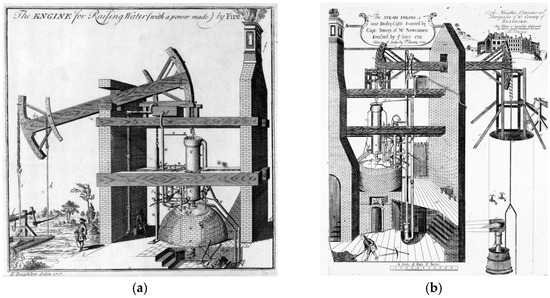
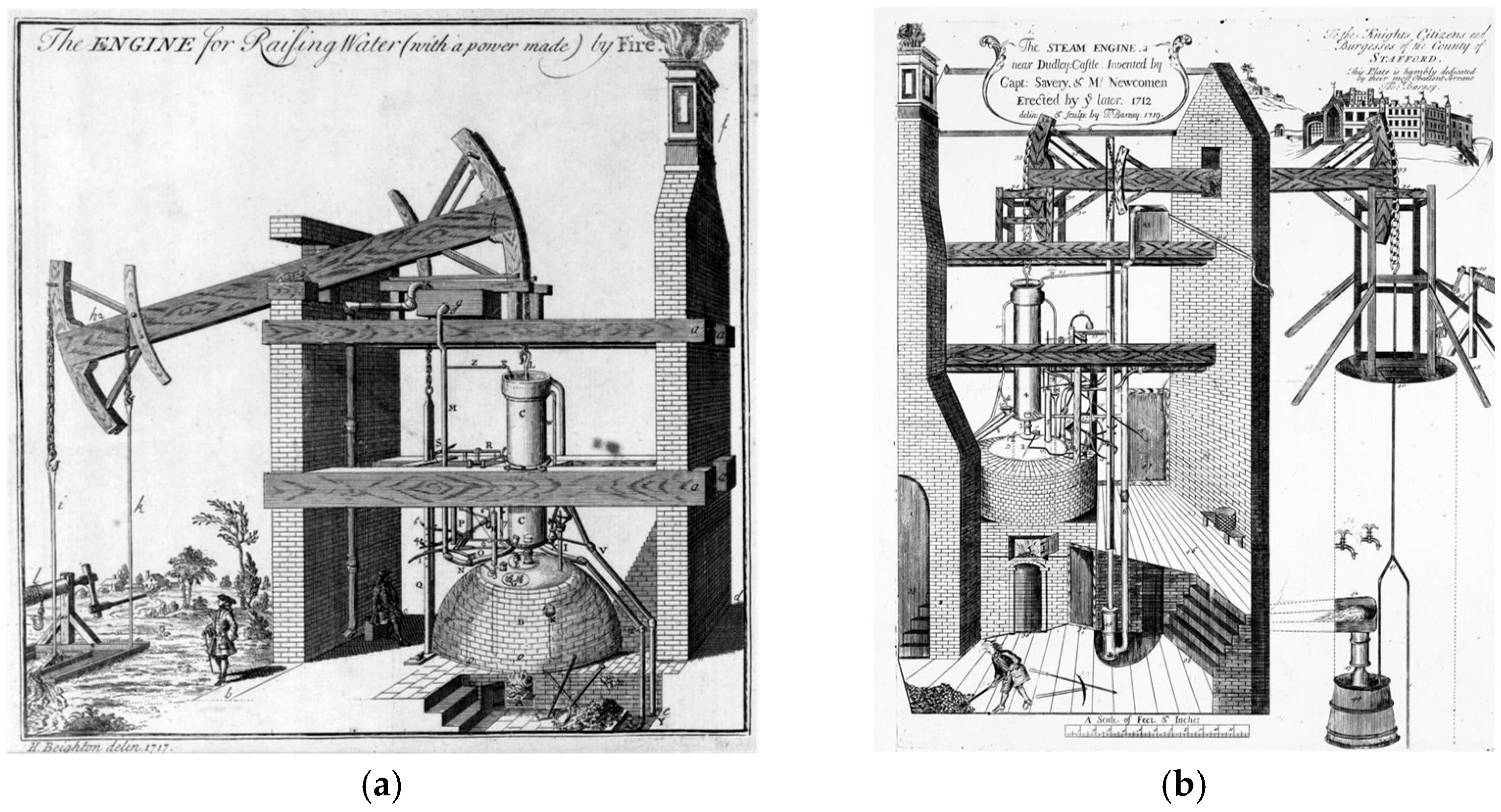
In the specific case of the Newcomen engine, the absence of an independent patent required the consultation of alternative historical and graphical evidence. The primary source used for digital reconstruction was Henry Beighton’s 1717 engraving of the Newcomen engine at Griff (Figure 2a) [37]. The engraving depicts the atmospheric engine erected by Newcomen at Griff Colliery, Warwickshire (UK), in 1714 and is considered the earliest known drawing, and the earliest surviving document, showing the construction of a Newcomen engine. It provided essential information on the overall arrangement of the machine, the configuration of its main components and the mechanical relationships between the cylinder, beam, boiler, injection system and pumping mechanism.
Figure 2.
Historical sources used for the digital reconstruction of the Newcomen engine: (a) Henry Beighton’s engraving of the engine at Griff, 1717 [37]; (b) Thomas Barney’s drawing of the engine installed near Dudley Castle, 1719, reproduced by Rolt and Allen [38].
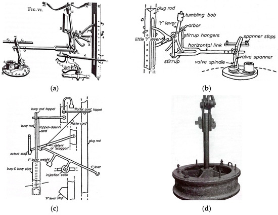
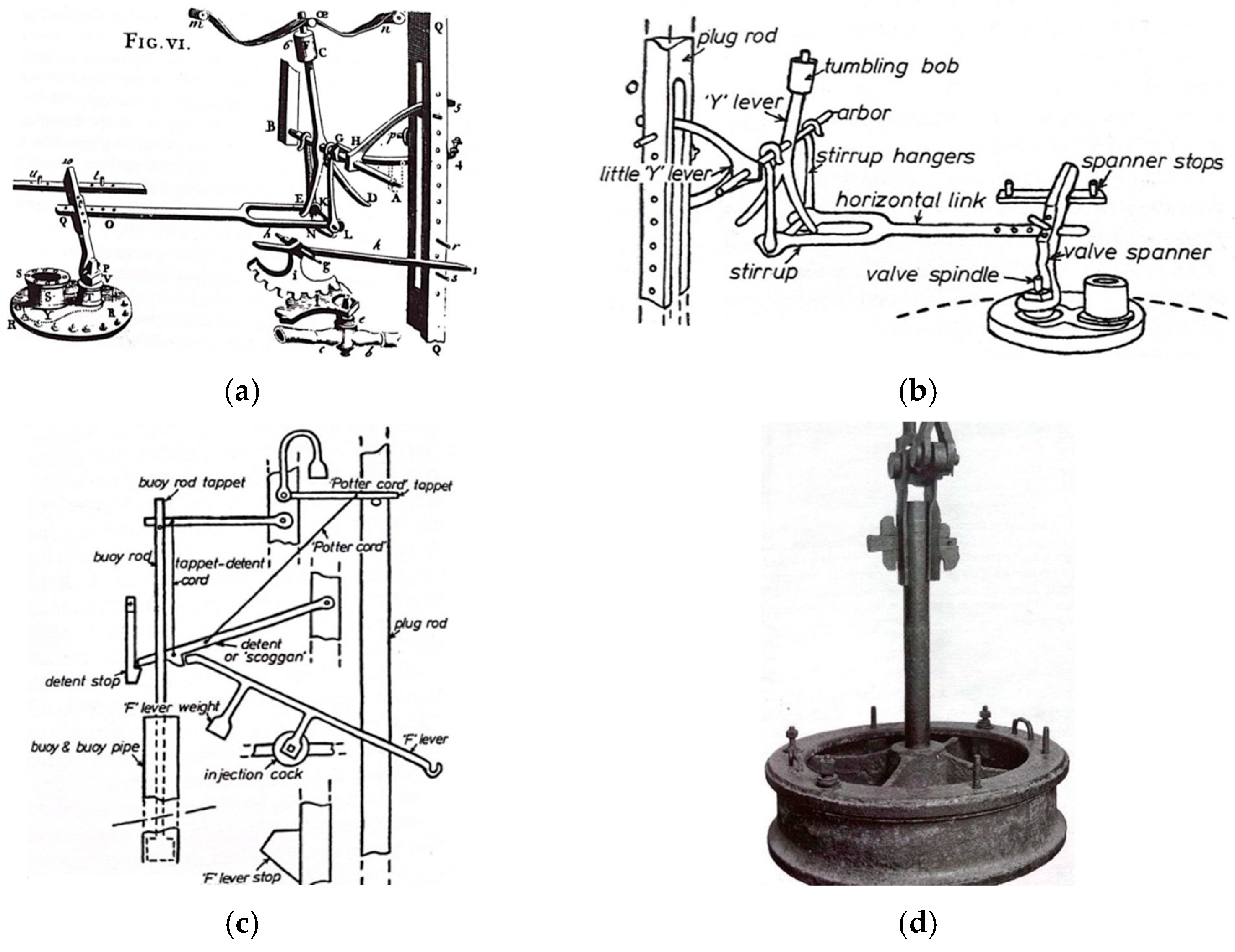
A second key documentary source was the work of Rolt and Allen, which reproduces a drawing prepared by Thomas Barney in 1719 depicting the engine erected near Dudley Castle in 1712 (Figure 2b). The comparative examination of this source and Beighton’s engraving made it possible to identify common construction features, assess differences between the two early installations and obtain a more reliable interpretation of the geometry and operating principles. A major advantage of the source compiled by Rolt and Allen is the extensive and detailed information that provides on the dimensions of the main components, particularly the cylinder and boiler, as well as on the materials used in many of the machine elements. It also includes descriptive texts explaining the engine’s operating cycle in detail. Furthermore, the source proved especially valuable for reconstructing internal components, as it contains detailed drawings and diagrams of the steam and injection valves, together with a photograph of the main-cylinder piston (Figure 3).
Figure 3.
(a–d) Documentary sources used to reconstruct the internal components of the Newcomen engine [38].
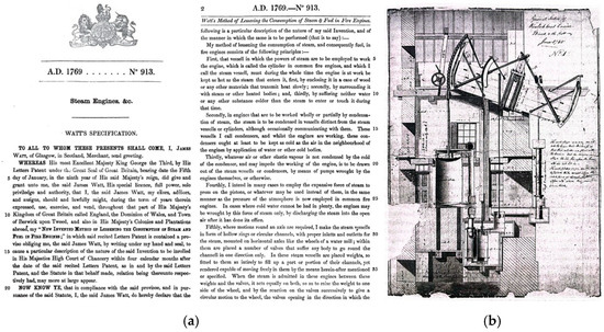
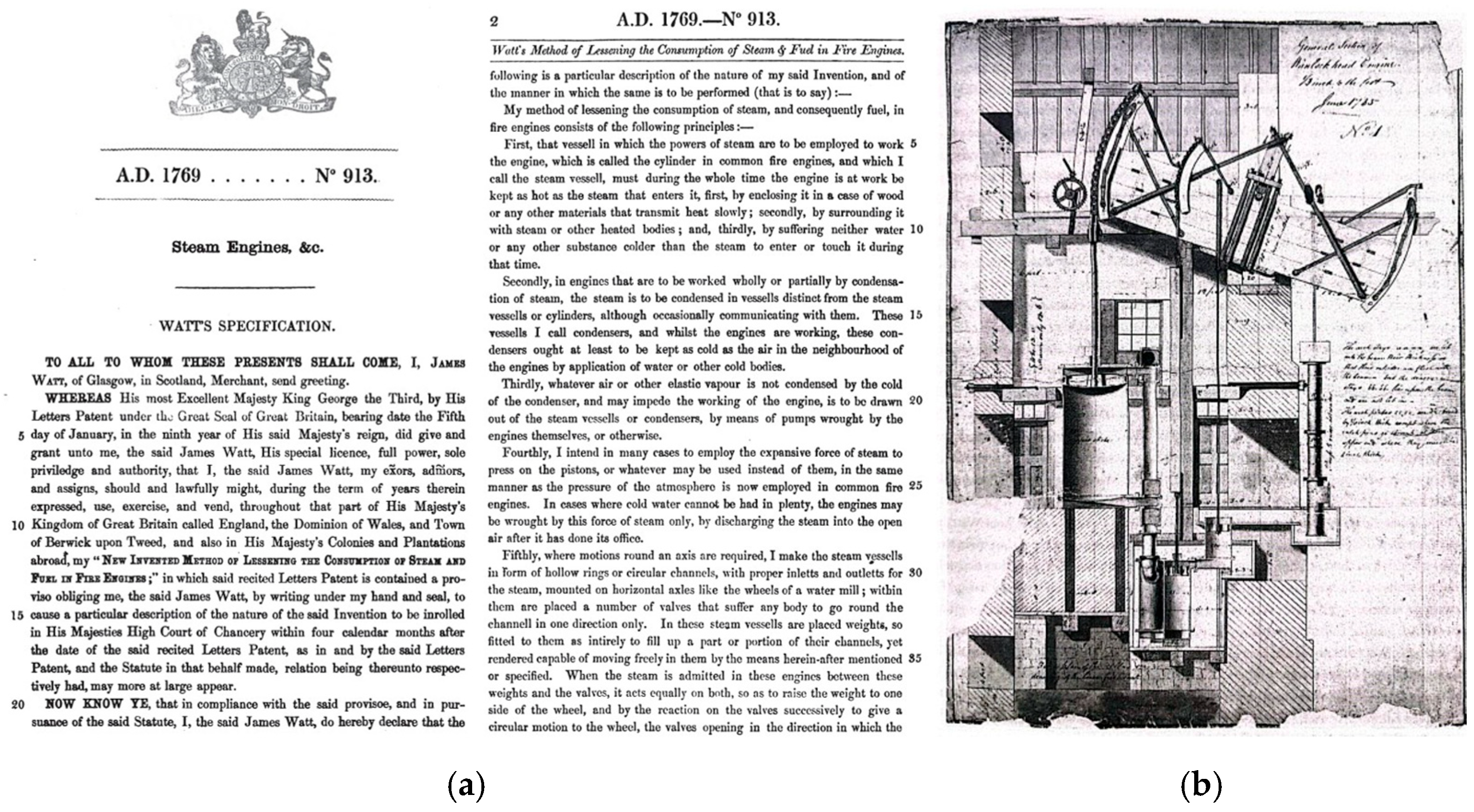
In the case of James Watt’s first steam-engine configuration, most of the information concerning its construction and operating principle was obtained directly from his 1769 patent (Figure 4a), which was treated as the principal primary source for reconstruction [39]. The document describes in detail the additional components and modifications introduced with respect to Newcomen’s atmospheric engine. These changes were primarily intended to improve the thermal performance of the system by reducing heat losses, maintaining the main cylinder at a more uniform temperature and transferring steam condensation to a separate chamber. The patent therefore provided the documentary basis for identifying the principal innovations incorporated into Watt’s design and for defining the geometry, arrangement and functional relationships of the components included in the three-dimensional model.
Figure 4.
Historical sources used for the digital reconstruction of the Watt engine (1769): (a) James Watt’s 1769 patent for the separate condenser and other improvements to the steam engine [39]; (b) General sectional drawing of the Wanlockhead pumping engine, designed by James Watt for the Margaret Mine, June 1785 [40].
In addition to the 1769 patent, the longitudinal sectional drawing of the Wanlockhead pumping engine (Figure 4b) was used as a complementary graphical source. Although the Wanlockhead drawing dates from 1785, approximately sixteen years after Watt’s 1769 patent, it was used only as complementary morphological evidence. The patent remained the primary source for identifying the technological features of Watt’s first configuration, whereas the later drawing was consulted solely to clarify the spatial arrangement and geometric relationships of components already documented in the patent. Accordingly, no construction feature was transferred from the 1785 engine to the 1769 reconstruction unless it was compatible with the principles explicitly described in the patent.
The drawing represents an atmospheric condensing engine designed by James Watt and supplied by Boulton & Watt for the Margaret Mine in Wanlockhead (Dumfries, Scotland). Dated June 1785, the original is attributed to James Watt, or to an assistant working under his supervision, and is held in the Museums Victoria collection under inventory number ST 41088 [40]. The drawing provided detailed information on the spatial arrangement and mechanical relationships between the main cylinder, beam mechanism, separate condenser, air pump, connecting pipes and pumping system. Although it corresponds to a later installation rather than Watt’s first engine configuration, its technical detail facilitated the interpretation of components that were only schematically described or represented in the 1769 patent. Consequently, it was used to support the geometric reconstruction and functional arrangement of the three-dimensional model, while the patent remained the primary documentary source for identifying Watt’s original innovations.
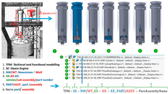
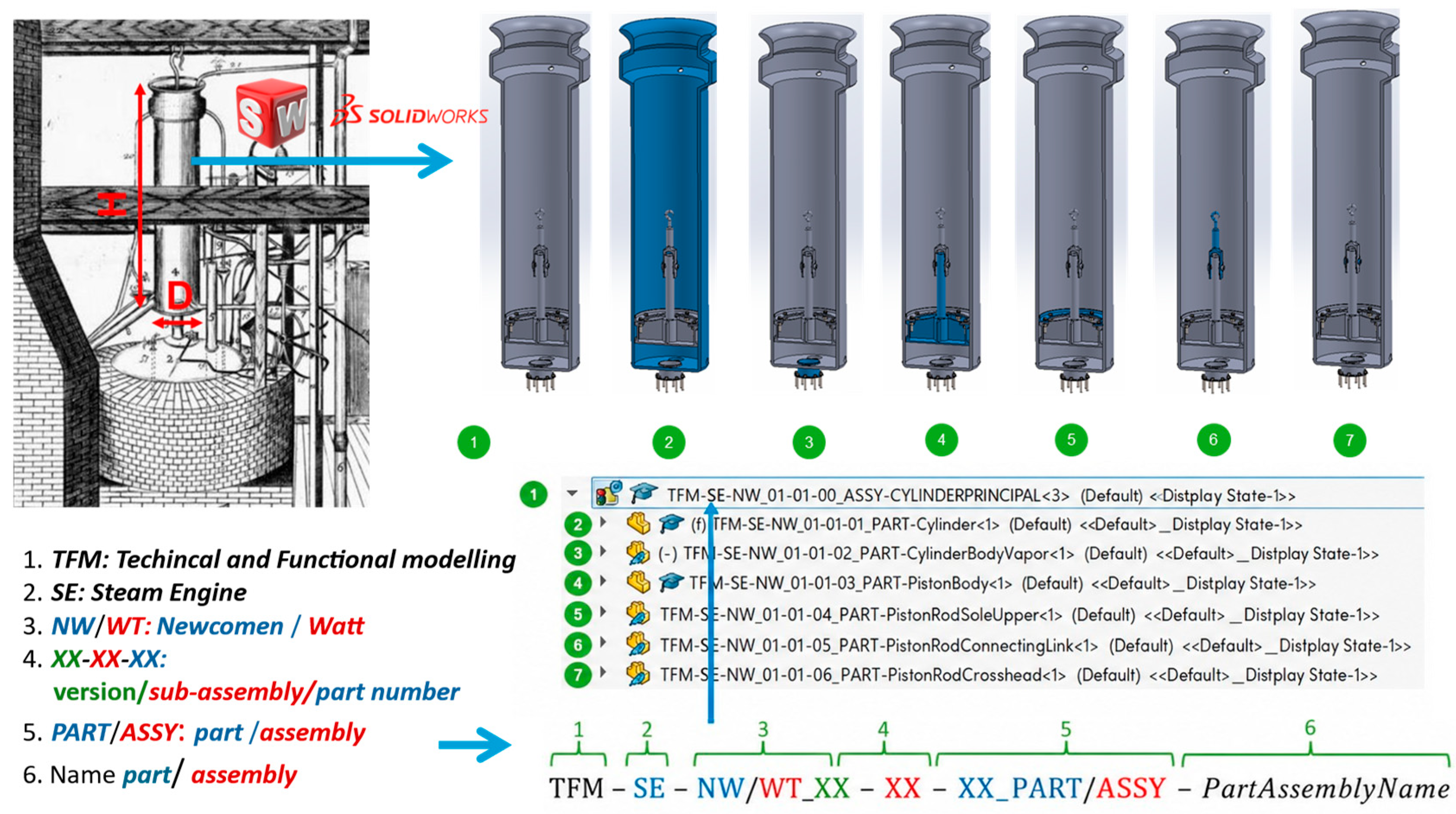
In the stage 2, based on the documentary information collected, the main components of each engine were identified and classified prior to geometric modelling. This stage was necessary to define the functional structure of the machines and to establish the relationships between individual parts and assemblies. Since the historical drawings were not always dimensioned, at least one reliable reference dimension was required to scale the remaining geometry. For the Newcomen engine, Rolt and Allen provide the diameter D = 533.4 mm (21 in) and height H = 2387.6 mm (7 ft 10 in) of the main cylinder. These dimensions were adopted as the primary scaling references for estimating the remaining dimensions of the engine from the available drawings and documentary evidence (Figure 5). Where dimensions could not be determined directly, proportional measurements were obtained from the graphical sources and adjusted to preserve the geometric and functional consistency of the assembly.
Figure 5.
Reference dimensions and coding system for parts and assemblies.
To make explicit the relationship between the documentary evidence and the reconstructed geometry, a traceability matrix was established for the principal components identified in Table 2. Given the large number of individual parts, subassemblies and assembly elements contained in the complete CAD model, the matrix was restricted to the principal components defining the structural, mechanical, hydraulic and functional configuration. For each component, the matrix identifies the documentary sources consulted, the type of evidence obtained, the reconstruction basis adopted, the corresponding evidence class and the validation procedure applied.
Table 2.
Document traceability matrix for the principal components of the reconstructed Newcomen and Watt steam engines.
The stage 3, the three-dimensional reconstruction, was carried out using SolidWorks 2016 CAD software. Each component was modelled individually and subsequently grouped into subassemblies corresponding to the main functional systems of the engine. These subassemblies were then integrated to produce the complete digital assembly. Owing to the large number of components involved, a standardised coding system was established to assign a unique identifier to each part and subassembly (Figure 5). This system facilitated the structured management of the digital model, ensured consistency throughout the reconstruction process and improved the traceability and reproducibility of the modelling workflow.
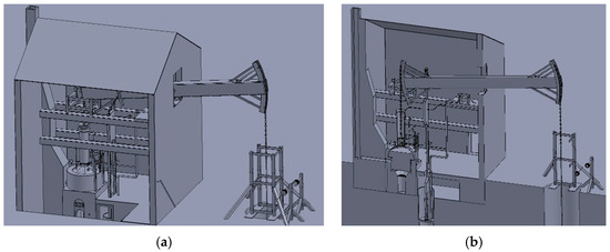
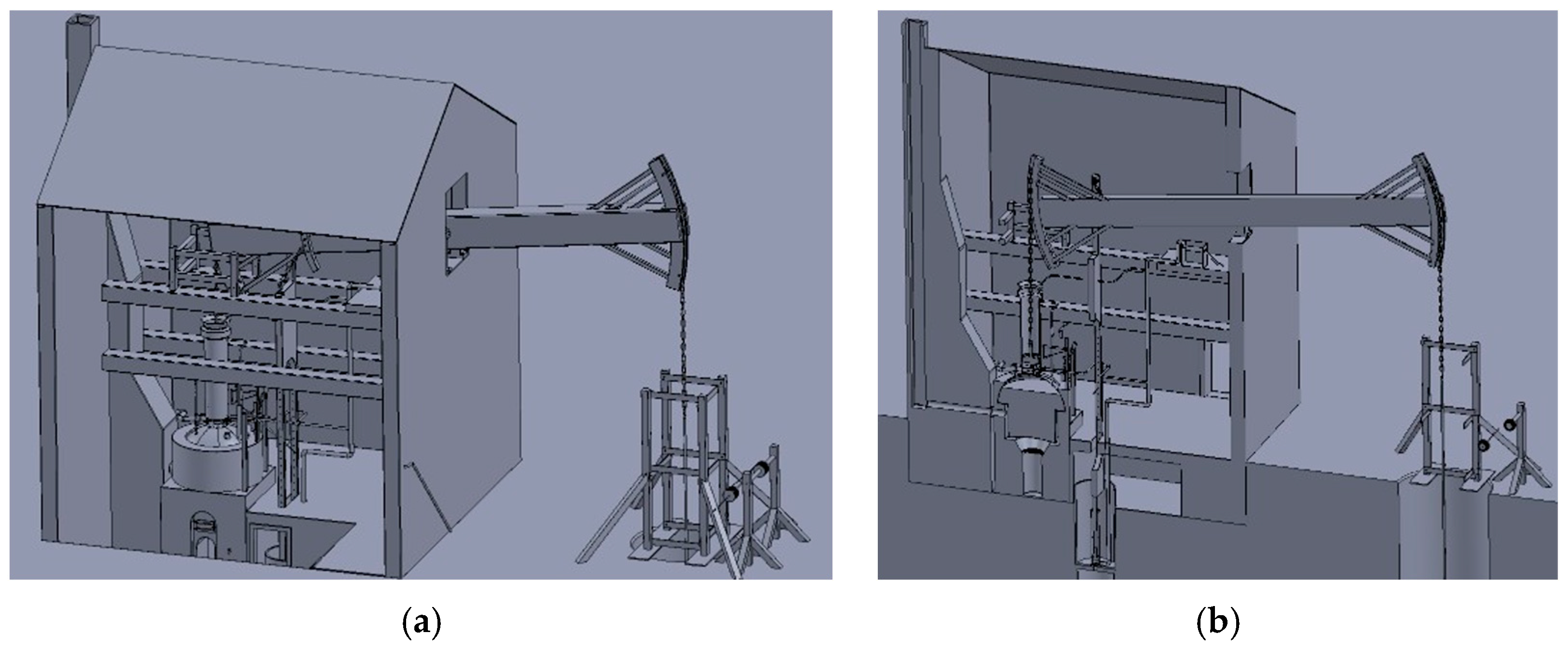
All individually modelled components and functional subassemblies were integrated into a final assembly representing the complete machine. Figure 6 shows an overall view and a sectional view of the reconstructed Newcomen engine, enabling both its external configuration and the arrangement of its internal components to be examined.
Figure 6.
(a) Overall and (b) sectional view of the digital model of Newcomen engine.
The sectional representation was also used to verify the relative positioning, mechanical connections and functional coherence of the different elements within the assembly. Along the stages 4 and 5, the reconstructed three-dimensional assemblies were subjected to a systematic validation process before being used for functional analysis and augmented reality visualisation. First, the geometric consistency of the models was verified by checking the dimensions, relative positioning and alignment of all components against the available historical drawings and documented reference dimensions. Particular attention was paid to the compatibility of the interfaces between interconnected elements to ensure that all assemblies could be completed without geometric interference.
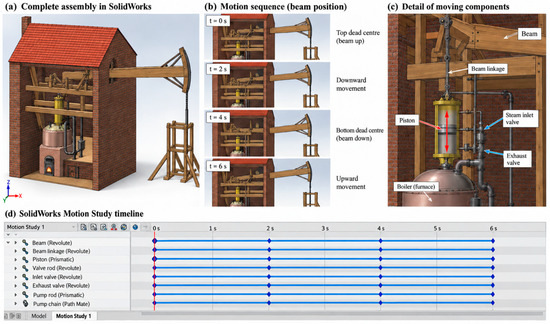
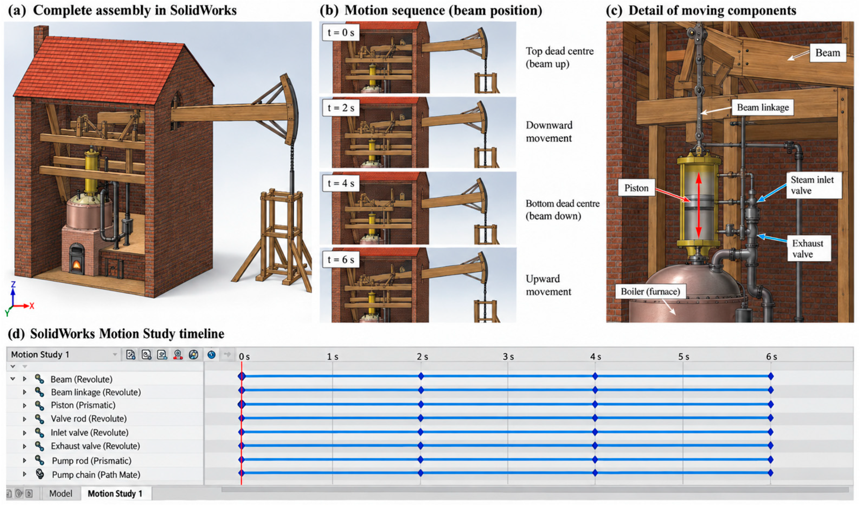
The kinematic consistency of the reconstructed assemblies was additionally verified using the Motion Study environment available in SolidWorks (Figure 7). The relative movements of the main interconnected components were simulated throughout the operating cycle in order to assess the compatibility of their mechanical connections, relative displacements, and motion constraints. Particular attention was paid to the coordinated movement of the beam, piston, pump rods, chains, valve mechanisms, and associated moving elements. This analysis made it possible to identify potential inconsistencies in the reconstructed geometry and to verify that the connections between components allowed the complete mechanism to operate without unintended interference or incompatible motion. Where inconsistencies were detected, the corresponding geometric assumptions were reviewed, and the affected components were adjusted before the final assembly was accepted.
Figure 7.
Motion Study in SolidWorks used to verify the kinematic behaviour and the coherence of the connections between components: (a) complete assembly of the reconstructed Newcomen engine; (b) sequence of beam positions during the operating cycle; and (c) detail of the main moving components and their mechanical connections; (d) SolidWorks Motion Study timeline.
Secondly, the functional coherence of each reconstruction was assessed by comparing the resulting assemblies with historical descriptions of the operating cycle. The sequence of movements of the principal mechanical elements (including the beam, piston, pump rod, connecting links and valve mechanisms) was examined to verify that their relative motions were compatible with the documented working principles of both engines. Whenever historical sources provided incomplete or conflicting information, the adopted solutions were selected according to mechanical feasibility, consistency with eighteenth-century engineering practice and agreement with the documented operating cycle. All interpretative decisions were recorded during the modelling process to ensure the traceability and reproducibility of the digital reconstruction.
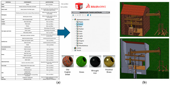
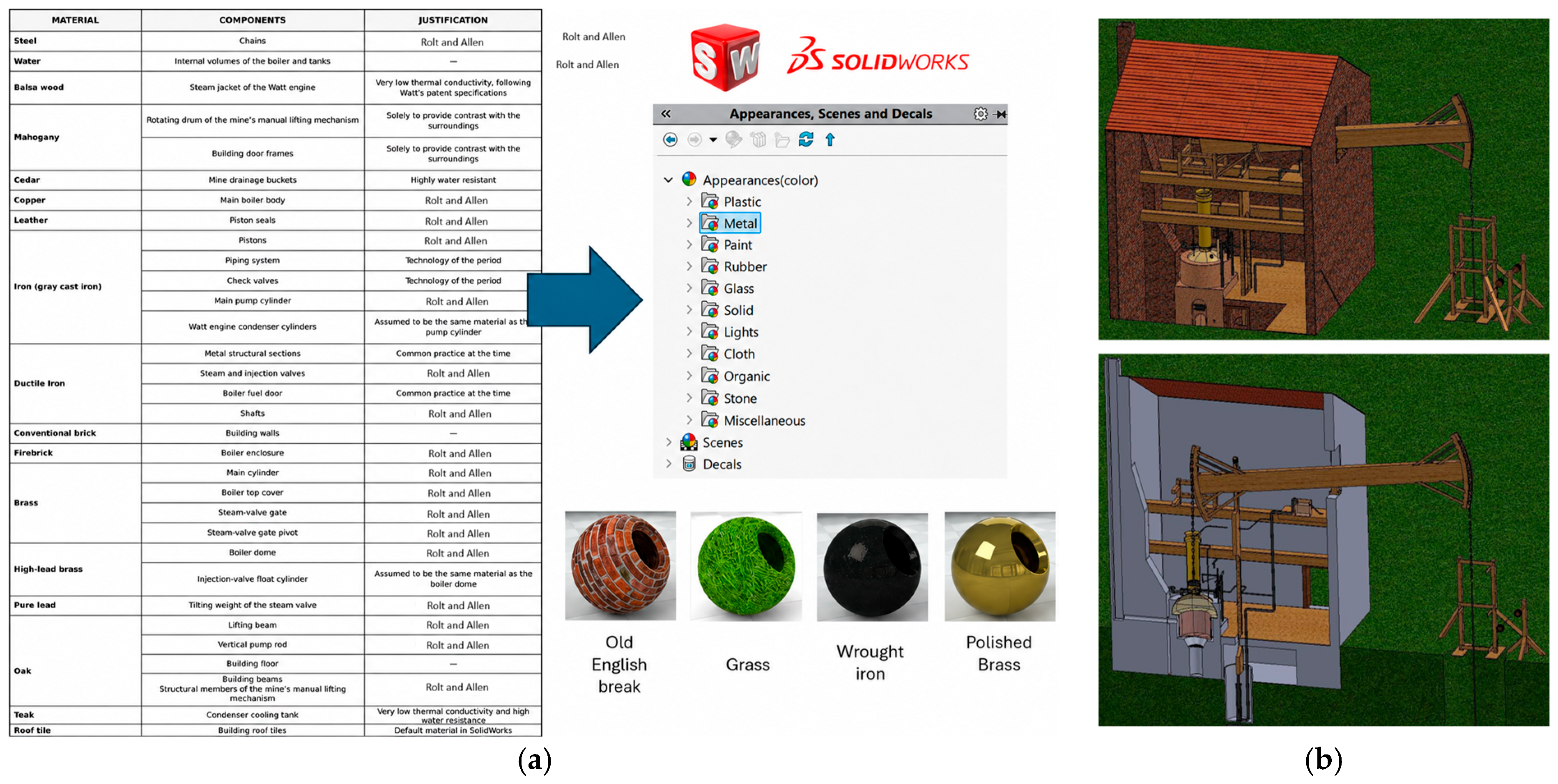
The developed digital models were subsequently used to conduct a comprehensive functional analysis of both engines, the results of which are presented in the following section. In the stage 6, materials were assigned to each three-dimensional component based on the information obtained from the consulted historical and technical sources. Where documentary evidence was available, the material definition reflected the original construction materials; otherwise, visually and functionally equivalent materials were selected while preserving the coherence of the reconstruction (Figure 8a). The corresponding surface properties and textures were then applied to reproduce the appearance of elements such as metals, timber, masonry and other construction materials. This stage improved the visual realism of the digital models and facilitated the identification and interpretation of the different components within the complete assemblies (Figure 8b).
Figure 8.
Texturing step: (a) Material assignation; (b) Textured overview and cross section of the digital model of Newcomen engine.
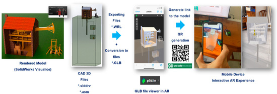
To enable the interactive visualisation of the reconstructed engines in augmented reality, the three-dimensional assemblies were processed through the workflow summarised in Figure 9. This workflow corresponds to the stage 7.
Figure 9.
Workflow for converting the reconstructed steam-engine model into an interactive augmented reality experience.
To enhance the visual realism of the reconstructed machines and prepare the models for their subsequent visualisation in augmented reality environments, the complete assemblies were rendered using SolidWorks Visualize. This process incorporated the previously assigned materials, surface textures, lighting conditions and camera settings to generate visually coherent representations of the machines and their surrounding structures. The rendered models were subsequently used as the basis for their optimisation and integration into the web-based augmented reality environment. The original CAD models, stored as SolidWorks part and assembly files (.SLDPRT and .SLDASM), were first reviewed to ensure that the geometry, component hierarchy, materials and relative positions of the different elements were correctly represented. The complete assemblies were then exported to the Virtual Reality Modeling Language (.WRL) format. This intermediate format was selected because it preserves the three-dimensional geometry and visual appearance of the model while facilitating its transfer from the CAD environment to external visualisation platforms.
The exported files were subsequently converted to the binary format (.GLB). This format integrates geometry, materials, textures and scene information into a single compact file, thereby simplifying model management and reducing the number of external resources required for online visualisation. This format also improved compatibility with web-based three-dimensional viewers and mobile augmented reality systems. Before publication, the converted models were checked to verify their orientation, scale, material appearance and geometric integrity, as format conversion may alter some of these properties.
The conversion from WRL to GLB was performed without polygon decimation in order to preserve the geometric detail of the reconstructed machinery. The original WRL model contained 1,820,748 triangular polygons and the resulting GLB retained the same polygon count, corresponding to a geometric reduction of 0%. Nevertheless, the binary conversion substantially reduced the storage requirements, from 72.28 MB for the WRL file to 22.27 MB for the final GLB file, representing a file-size reduction of 69.18%. The final GLB comprised 910,395 vertices distributed among 649 meshes. No raster texture maps were embedded in the GLB; instead, the visual appearance of the components was represented through material properties, including base colour, metallicity, roughness and transparency. Despite retaining complete polygonal geometry, the model could be successfully loaded and interactively manipulated on the iOS and Android mobile configurations described below.
The resulting .GLB files were uploaded to the web-based 3D visualisation platform p3d.in, which was used to host and display the models. The external web platform was deliberately selected to minimise software-development requirements and facilitate access to the reconstructed models through standard mobile devices, while preserving a clear separation between the research-controlled reconstruction pipeline and the third-party visualisation service. This approach avoided the need to develop a dedicated augmented reality application and allowed the reconstructed machines to be accessed through a standard web browser. Once each model had been uploaded and its visualisation parameters had been configured, the platform generated a unique web link providing direct access to the corresponding interactive model.
To facilitate access from mobile devices and support its integration into the Virtual Museum, each web link was encoded as a quick-response code using QR Code Monkey. The QR codes act as direct access points to the digital reconstructions and can be incorporated into museum displays, educational materials, posters or online resources. When scanned with a compatible smartphone or tablet, the code redirects the user to the hosted model and activates the augmented reality visualisation mode.
The AR experience used a markerless, surface-based tracking and anchoring approach. After the hosted model was opened in AR mode, the mobile device camera was used by the platform to detect a suitable physical surface in the surrounding environment. The digital reconstruction was then anchored to the detected surface, providing a spatial reference for its placement while the user moved around the scene. Once positioned, the model could be interactively translated, rotated and scaled. The QR code was used exclusively to provide direct access to the hosted model and did not act as a fiducial marker for tracking or anchoring. The underlying low-level tracking functions were handled by the AR capabilities supported by the mobile device and the external platform rather than by custom tracking algorithms developed in this study. This procedure makes it possible to visualise both the overall configuration of the engine and the spatial relationships between its components without requiring access to a physical working example.
A markerless surface-based approach was selected instead of object-recognition or image-tracking solutions because the reconstructed machines may no longer exist, may be inaccessible, or may not be available in a configuration suitable for recognition. Image-based tracking would additionally require a predefined physical reference and would constrain the visualisation to a specific marker or location. Surface-based anchoring instead enables the reconstructed model to be placed freely on any suitable detected surface and interactively repositioned, rotated, and scaled, which is more consistent with the intended museum and remote-access use of the digital heritage resources.
Compatibility of the web-based AR implementation was tested on both iOS and Android mobile devices using current stable software environments. On iOS, the experience was verified on an iPhone running iOS 26.6.1 using the Safari browser. On Android, compatibility was tested on devices running Android 17 using Google Chrome 152.0.7977.82 and Microsoft Edge Mobile 152.0.4191.53. In all configurations, the tests verified access to the hosted model, activation of the AR mode, detection of a suitable physical surface, model placement and anchoring, and interactive manipulation through translation, rotation, and scaling.
In the final stage (stage 8), the validated and AR-ready digital reconstructions were integrated into the Virtual Museum of the School of Industrial Engineering at the University of Malaga as heritage dissemination resources. This integration was conceived as the final layer of the workflow, linking the documented reconstruction process with its subsequent public and educational use. The virtual museum provides a structured environment in which the models can be accessed together with the associated historical and technical information, allowing the reconstructed machinery to be explored beyond the limitations imposed by the absence, inaccessibility or non-operational condition of the original assets. In this way, the digital models become reusable heritage resources that support the preservation, interpretation, and dissemination of the technological knowledge embodied in the reconstructed machines.
The workflow therefore provides a relatively simple and reproducible method for transforming CAD reconstructions of historical machinery into web-accessible augmented reality resources and can be applied to other industrial heritage assets represented by three-dimensional models.
3. Functional Analysis
The following section presents a functional analysis of Newcomen’s atmospheric steam engine and examines the modifications subsequently introduced by James Watt based on his initial developments and 1769 patent. The analysis focuses on the operating sequence of each machine, the role of its main components and the mechanical and thermodynamic relationships governing the pumping cycle. Particular attention is given to identifying which elements of Newcomen’s original configuration were retained, modified, or supplemented in Watt’s design, thereby enabling the technological evolution between both machines to be assessed from a comparative perspective.
3.1. Newcomen Engine
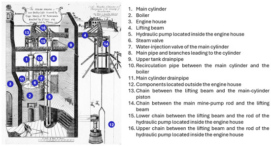
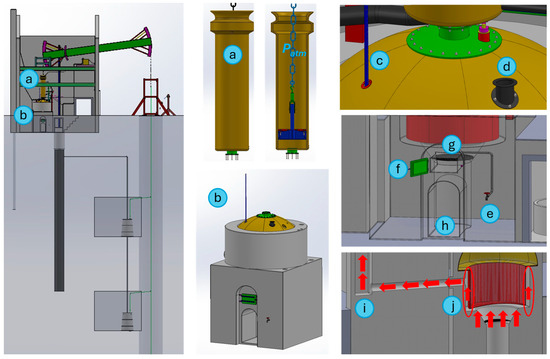
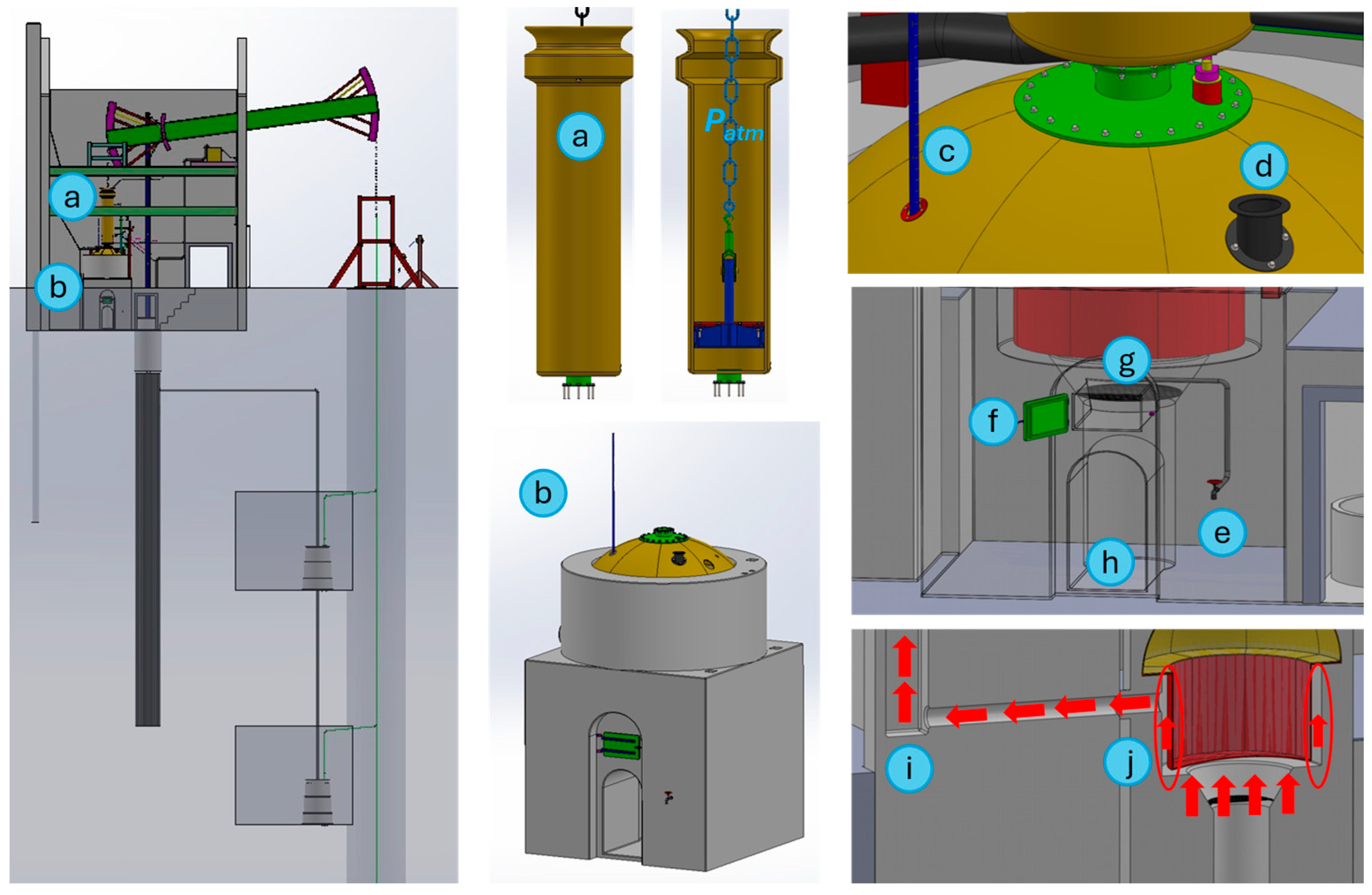
The main components of the Newcomen engine are identified in Figure 10. Their selection and functional classification were based on the comparative analysis of the available historical evidence, particularly Henry Beighton’s 1717 engraving of the Newcomen engine at Griff and the work of Rolt and Allen, which reproduces Thomas Barney’s 1719 drawing of the engine installed near Dudley Castle [38]. Together, these sources provided the documentary basis for defining the overall configuration of the machine, identifying its principal mechanical and hydraulic elements and establishing the functional relationships between them.
Figure 10.
Main components and auxiliary systems of the Newcomen engine [38].
Figure 11 shows the main cylinder, boiler, furnace and flue-gas circulation system of the Newcomen engine.
Figure 11.
Main cylinder, boiler, furnace, and flue-gas circulation system of the Newcomen engine.
The Newcomen engine operated according to the atmospheric principle, with the upper side of the main cylinder remaining open to the atmosphere (Figure 11a). Steam was generated in a copper boiler containing the water required for operation, which was heated by the combustion of coal in the furnace located below it (Figure 11b). Before starting the engine, the operator had to verify that the water level inside the boiler was sufficient to generate the required amount of steam. This level was monitored visually by means of a graduated rod connected to a float (Figure 11c).
The boiler was also equipped with a filling hatch (Figure 11d) and a drain cock (Figure 11e), which enabled the water volume to be replenished or reduced when necessary. The combustion system comprised a coal-charging door (Figure 11f), a grate supporting the fuel during combustion (Figure 11g) and an ash pan for collecting and removing the resulting residues (Figure 11h).
The boiler was enclosed within a brickwork structure (Figure 11i). A gap was left between the boiler surface and the surrounding masonry, forming a flue through which the hot combustion gases circulated. This arrangement allowed heat to be transferred not only through the base of the boiler but also across part of its lateral surface before the gases were discharged through the chimney (Figure 11j). By increasing the surface area exposed to the hot gases, this configuration improved heat transfer to the water and contributed to a more effective steam-generation process.
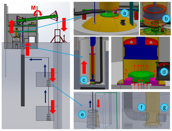
The operation of the Newcomen engine was organised into two fundamental stages: the charging phase and the power phase. During the charging phase (Figure 12), the steam-admission valve (Figure 12a) opens, allowing steam from the boiler to enter the main cylinder (Figure 12b). The steam fills the space beneath the piston at approximately atmospheric pressure, while the weight of the mine-pump rods causes the opposite end of the beam to descend and the piston to rise. This produces a clockwise rotation of the beam. Shortly before the piston reaches the end of its stroke, the steam valve closes, promoting a gradual deceleration of the moving system and reducing the risk of impact at the stroke limit.
Figure 12.
Charging phase of the Newcomen engine.
At the same time, the piston of the pump located inside the engine house rises (Figure 12c), generating a pressure reduction that draws water from the lower reservoir into the pump cylinder. A non-return valve (Figure 12d) prevents the extracted water from flowing back into the supply pipe.
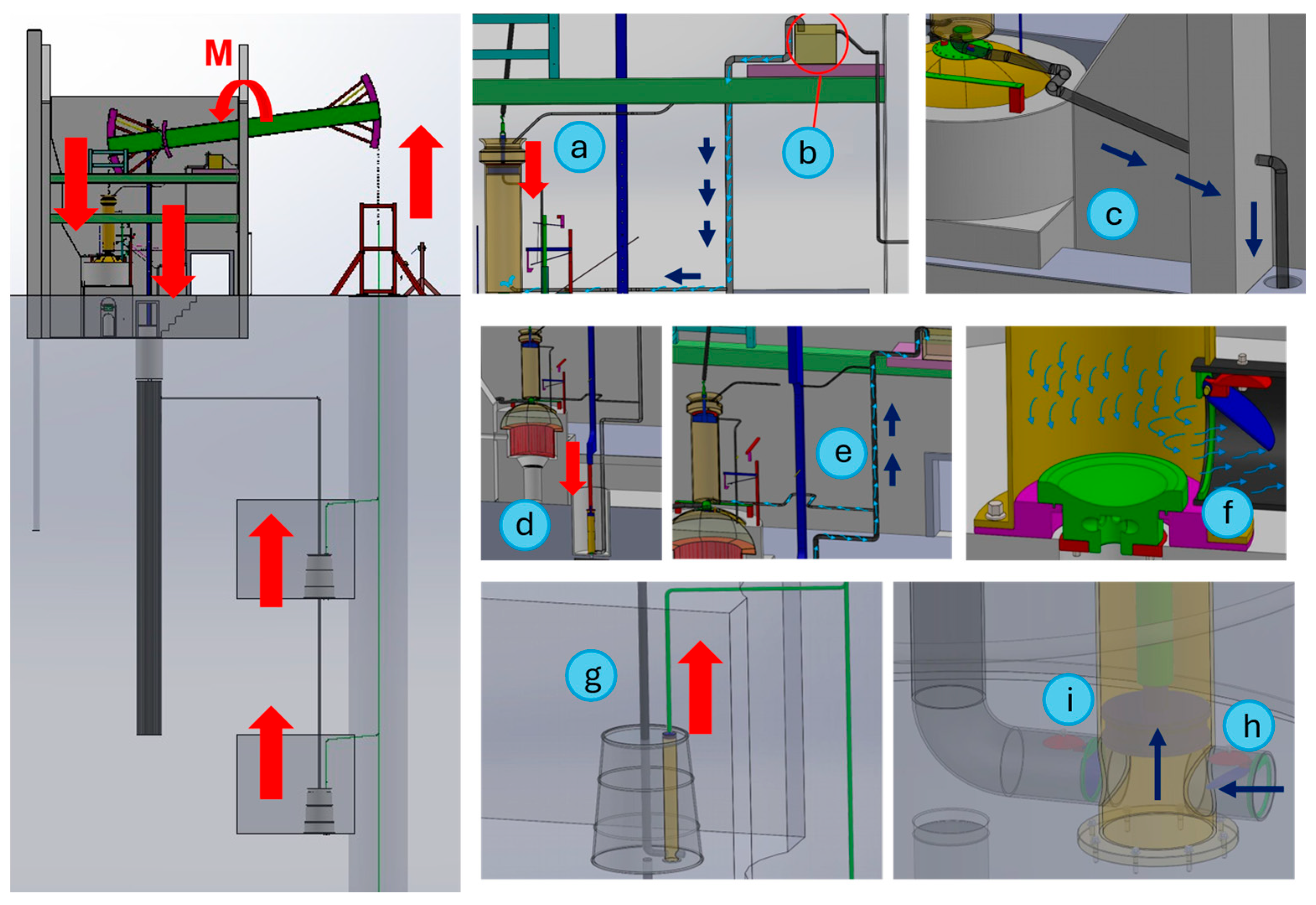
While the pump inside the engine house removed water from the sump beneath the structure, a complementary lifting process took place within the mine. Intermediate reservoirs were arranged at different depths to collect water draining from the galleries and transfer it progressively towards the upper sump, from which it could subsequently be discharged by the engine-house pump. At the beginning of the charging phase, the mine-pump cylinders were filled with water (Figure 12e). Their downward movement displaced the water upwards, enabling its gradual transfer from one level to the next. Because the effective delivery head of each pump stage was limited, several pumps were installed in series along the vertical mine shaft. The filling and discharge of each cylinder were controlled by two non-return valves. During this phase, the delivery valve (Figure 12f) remained open, whereas the inlet valve (Figure 12g) remained closed, thereby ensuring unidirectional water flow.
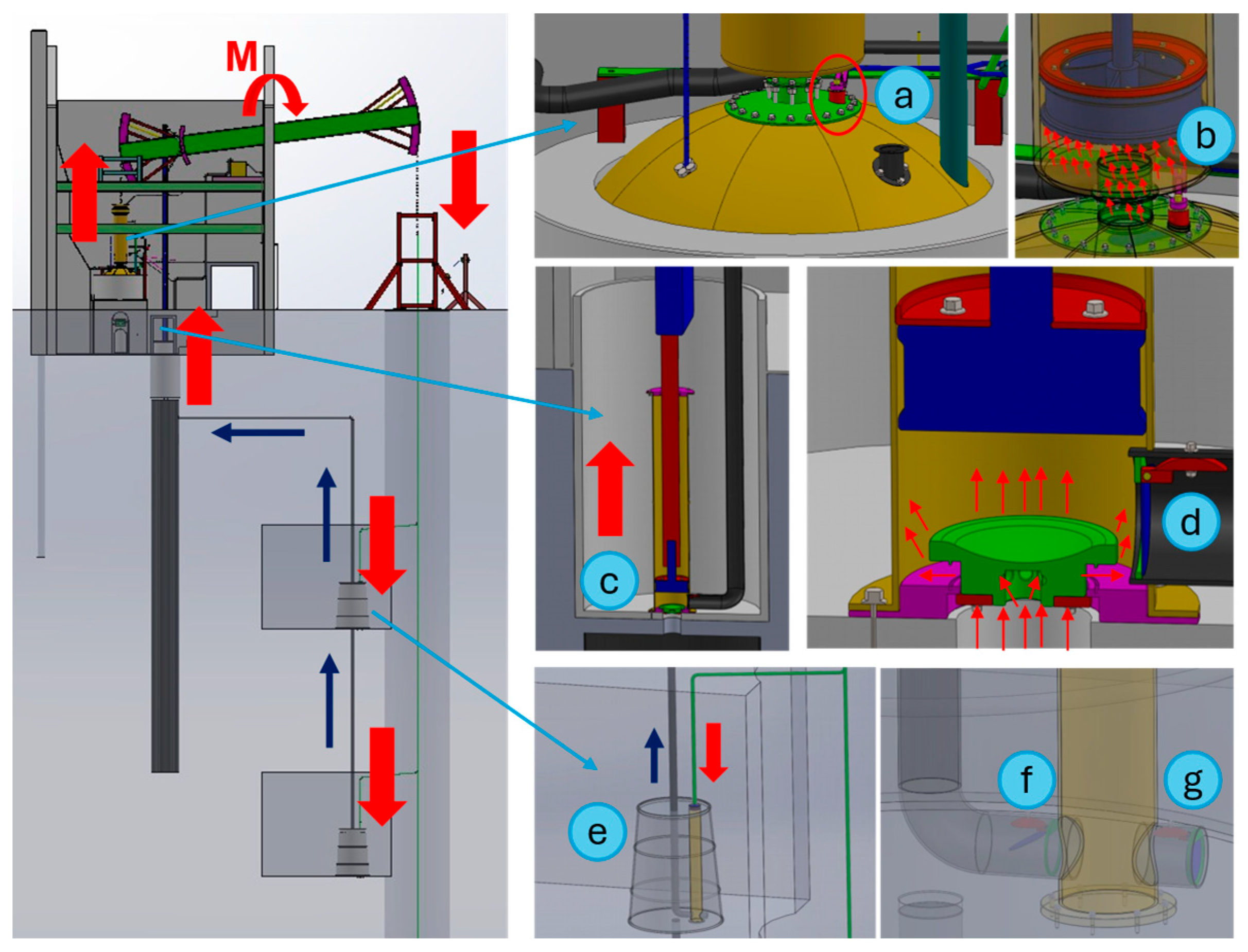
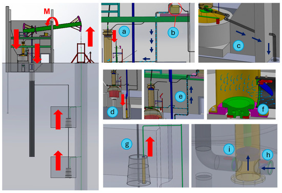
During the power phase (Figure 13), the control mechanism closes the steam-admission valve and opens the cold-water injection valve (Figure 13a). Water from the upper reservoir (Figure 13b) is then introduced into the main cylinder, rapidly cooling and condensing the steam. The resulting sudden pressure reduction below the piston allows atmospheric pressure acting on its upper surface to force it downwards, causing the beam to rotate counterclockwise. The condensate and injected water are subsequently discharged from the cylinder through a drainpipe leading outside the engine house (Figure 13c).
Figure 13.
Power phase of the Newcomen engine.
During the same phase, the piston of the pump located in the lower reservoir moves downwards (Figure 13d), forcing water from the sump towards the upper reservoir (Figure 13e) through the corresponding non-return delivery valve (Figure 13f). This replenishes the water consumed during the cylinder-cooling and condensation process. Simultaneously, the pistons of the pumps arranged along the mine shaft move upwards (Figure 13g), drawing water from the intermediate reservoirs through the opening of their inlet non-return valves (Figure 13h). Their delivery valves remain closed during this movement, preventing the water already raised from flowing back into the pump cylinders (Figure 13i). Once this sequence is completed, the operating cycle restarts: the injection valve closes and the steam-admission valve opens, initiating a new charging phase.
3.2. Watt Engine (1769)
The steam engine patented by James Watt in 1769 retained the basic structural and operating principles of Newcomen’s design while incorporating two decisive improvements that substantially increased its thermal efficiency: the steam jacket surrounding the working cylinder and the separate condenser.
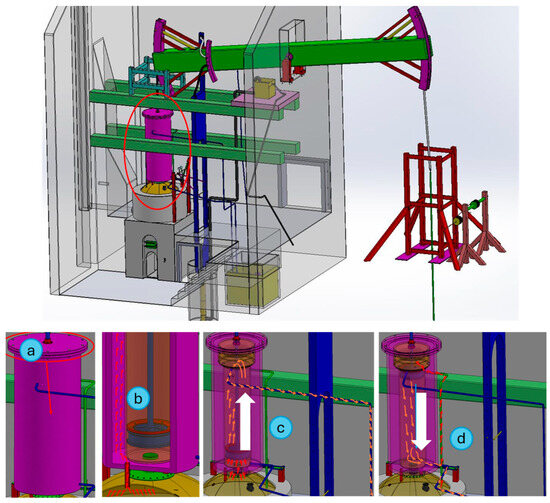
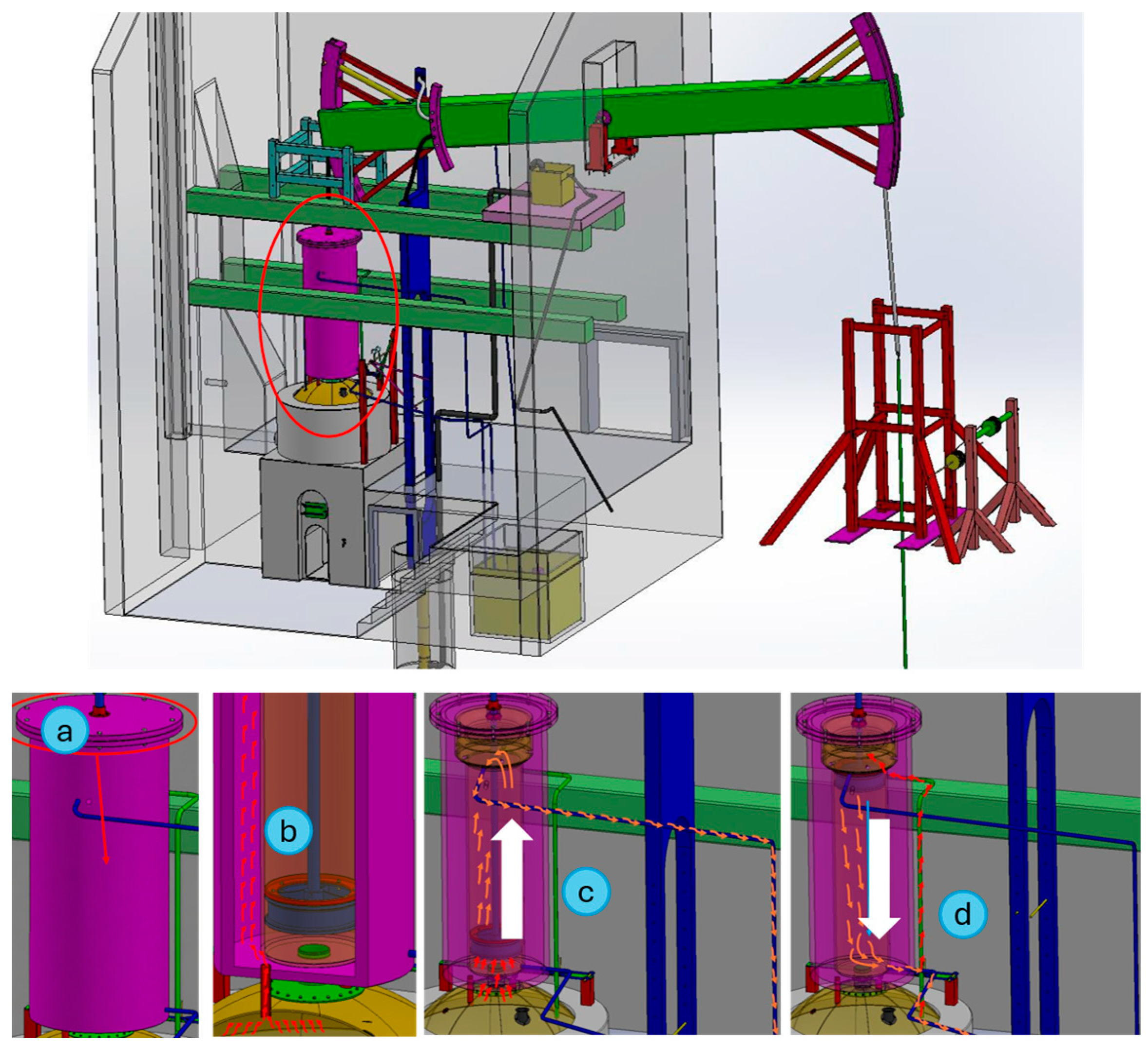
The first innovation consisted of enclosing the main cylinder within a steam jacket (Figure 14), thereby reducing heat losses and maintaining the working surfaces at a more uniform temperature.
Figure 14.
Steam jacket and circulation of heating steam around Watt’s working cylinder.
Unlike the open-topped cylinder of the Newcomen engine, Watt’s cylinder was closed at its upper end (Figure 14a). However, this first configuration remained single-acting: steam admitted above the piston replaced atmospheric pressure as the force producing the downward power stroke, whereas the return stroke was still driven by the weight of the pump rods. Watt’s double-acting engine, in which steam acted alternately on both sides of the piston, was developed and patented later, in 1782.
A portion of the steam generated in the boiler circulated through the space between the jacket and the cylinder wall (Figure 14b), helping to maintain the cylinder at a high and nearly constant temperature and reducing premature condensation during steam admission. Since condensation no longer occurred inside the working cylinder, as in Newcomen’s engine, Watt introduced a separate evacuation circuit through which steam was transferred from the cylinder to the condenser during the relevant stages of piston motion (Figure 14c,d). This arrangement prevented the repeated cooling and reheating of the main cylinder and therefore reduced thermal losses while preserving the reciprocating operating cycle of the pumping engine.
The second major improvement introduced by Watt to increase the efficiency of the system was the separate condenser (Figure 15). This device comprised three interconnected cylinders immersed in a cold-water tank, with the aim of promoting the rapid and efficient condensation of the steam discharged from the main working cylinder. The steam first entered the condenser cylinder, where it was suddenly cooled by contact with the refrigerated surfaces, causing it to condense (Figure 15a).
Figure 15.
Separate condenser and associated steam and condensate circuits in Watt’s 1769 engine.
The resulting condensate was then transferred through the lower connection to the second cylinder, where it was displaced by a piston driven by the main beam of the engine (Figure 15b). This controlled transfer was governed by a system of flap valves that allowed the water to pass beneath the piston during its downward stroke while preventing reverse flow during the upward stroke, thereby ensuring unidirectional movement of the fluid (Figure 15c). The water raised in the second cylinder was subsequently conveyed through an additional pipe fitted with a non-return valve to a collection cylinder, from which it was continuously discharged into a drainage well (Figure 15d). By relocating condensation outside the main cylinder, this arrangement prevented the repeated cooling of the working surface and considerably reduced the thermal losses characteristic of Newcomen’s design.
4. Discussion
The comparative functional analysis indicates that Watt’s first steam-engine configuration did not represent a complete departure from the operating principles established by Newcomen. Both machines retained the reciprocating beam mechanism, the pumping function and the use of steam condensation to generate the pressure difference required for piston motion. The principal transformation introduced by Watt concerned the thermal organisation of the system rather than its fundamental mechanical architecture. In the Newcomen engine, condensation occurred directly inside the working cylinder through the injection of cold water, resulting in repeated cooling and reheating of the cylinder during each operating cycle. Watt’s configuration relocated condensation to a separate chamber and maintained the working cylinder at a higher and more uniform temperature by means of the steam jacket. The technological advance can therefore be interpreted as a systematic optimisation of an established mechanical concept through improved thermal management.
The three-dimensional reconstructions make the spatial and functional consequences of these modifications particularly evident. Watt’s solution required additional pipes, valves, condenser cylinders and condensate-extraction mechanisms, thereby increasing the constructive complexity of the installation. However, this greater complexity allowed the thermal and mechanical functions of the engine to be more clearly separated. From a technological-history perspective, the comparison illustrates how significant innovation may result from the progressive reorganisation and optimisation of an existing system rather than necessarily from the introduction of an entirely new mechanical principle. From a heritage perspective, the digital reconstruction also makes visible relationships between steam circulation, water management and mechanical motion that are difficult to interpret from isolated historical drawings or descriptions alone.
Beyond this specific comparison, the methodological contribution of the study lies in the integration of the different stages required to transform incomplete historical evidence into an organised, mechanically coherent and interactively accessible digital reconstruction. Documentary analysis, three-dimensional modelling and immersive visualisation have individually been widely applied in digital heritage research. Previous studies have addressed the integration of heterogeneous documentary evidence, the digital reconstruction of historical machinery, computer-aided engineering analysis, the documentation of uncertainty and interpretative decisions and the application of augmented and virtual reality to heritage visualisation and dissemination. The present approach builds upon these established techniques but integrates them within a single engineering-oriented sequence encompassing documentary assessment, component identification, part modelling, organisation into functional subassemblies, complete mechanical assembly, kinematic verification and subsequent transformation into a web-accessible AR resource. Thus, the contribution does not reside in any individual digital technique, but in the formalisation of a transferable source-to-assembly-to-motion-to-AR workflow.
An important aspect of this methodology is the explicit treatment of uncertainty. Historical reconstruction inevitably involves different levels of documentary support, particularly when the original machinery no longer survives in a complete and accessible configuration. The traceability matrix introduced in the revised methodology distinguishes between elements that are directly documented (D), inferred from proportional or functional relationships (I), reconstructed using analogous historical evidence (R), and intentionally simplified (S). This distinction is particularly important because geometric coherence alone cannot demonstrate historical accuracy when the underlying documentary evidence is incomplete. Making these categories explicit allows the resulting digital model to be interpreted not as a homogeneous representation of equal certainty, but as a structured reconstruction in which the evidential basis of the principal components can be critically assessed.
The validation strategy must consequently be understood within the limitations imposed by the surviving historical evidence. Wherever reliable dimensions were available, these were used as direct geometric constraints; for example, the documented diameter and height of the Newcomen main cylinder were adopted as primary scaling references for the remaining geometry. The reconstructed assemblies were subsequently checked for dimensional consistency, relative positioning, alignment, mechanical interfaces and absence of unintended interference, while their functional coherence was compared with historical descriptions of the operating cycle. In the revised methodology, this validation was further extended through SolidWorks Motion Study to verify the compatibility of the relative movements and constraints of the principal interconnected components. In the absence of a complete surviving original configuration that could provide an independent geometric ground truth, conventional error indicators would not necessarily represent historical accuracy. The combination of documentary traceability, geometric consistency, interface compatibility and kinematic verification is therefore considered more appropriate for the type of reconstruction undertaken here. Accordingly, the geometric and kinematic validation performed in this study should be interpreted as evidence of mechanical consistency and documentary plausibility, rather than as absolute proof of the historical accuracy of the reconstructed geometry.
The historical context plays a fundamental role in this process. In historical machinery reconstruction, chronological and technological information is not merely descriptive background but can be essential for assessing whether a reconstructed solution is plausible for a particular period. This is especially relevant for Watt’s model, where the 1769 patent constitutes the primary source for identifying the technological principles of the first patented configuration, whereas the 1785 Wanlockhead drawing is used only as complementary morphological evidence. Maintaining this hierarchy prevents later construction details from being retrospectively attributed to the earlier design and illustrates why reconstruction decisions must be interpreted in relation to their documentary and technological context.
The final transformation of the CAD models into web-based augmented-reality resources extends the workflow from technical reconstruction to interactive digital deployment. Rather than developing a dedicated application, the adopted architecture separates the validated heritage model from the visualisation platform, facilitating access through standard mobile devices and reducing software-development and maintenance requirements. The use of markerless surface-based anchoring also allows the reconstructed machines to be positioned independently of the presence of an original physical object or predefined image marker, which is particularly appropriate for industrial heritage assets that may be lost, inaccessible or preserved only partially. Quantitative analysis of the WRL-to-GLB conversion further showed that the original polygonal geometry could be retained while substantially reducing the storage requirements through the more compact binary representation of the GLB format.
At the present stage, the AR component should therefore be interpreted primarily as the technical deployment stage of the proposed methodology rather than as a demonstrated measure of educational or interpretative effectiveness. The next stage of the research will extend this technical implementation through a user-centred evaluation of usability, interaction and heritage interpretation, involving appropriately characterised participants and standardised instruments such as the System Usability Scale (SUS). This subsequent evaluation will make it possible to complement the technical validation presented here with evidence regarding the user experience and the interpretative potential of the resulting digital heritage resources.
5. Conclusions
The main conclusions of this work can be summarised as follows:
- This study proposes a systematic and reproducible workflow for the digital reconstruction and interpretation of historical steam engines by the combined application of documentary analysis, simple reverse-engineering techniques, three-dimensional CAD modelling, rendering and augmented reality visualisation. Although applied to the Newcomen and Watt engines, the proposed workflow can be adapted to other historical machines for which physical evidence or technical documentation is incomplete or dispersed.
- The three-dimensional models enabled the main components, mechanical relationships, fluid circuits and operating sequences of both machines to be examined from an integrated functional perspective. In the Newcomen engine, the reconstruction facilitated the interpretation of the coordinated operation of the boiler, main cylinder, beam mechanism, injection system, auxiliary pumps and staged mine-drainage system.
- The comparative functional analysis indicates that Watt’s first steam-engine configuration did not represent a radical departure from the principles established by Newcomen. Instead, it retained the fundamental pumping architecture and reciprocating beam mechanism while introducing a progressive optimisation of the thermal process.
- The steam jacket and separate condenser constituted the principal improvements incorporated into Watt’s first configuration. By maintaining the working cylinder at a more uniform temperature and relocating condensation to an independent chamber, these modifications reduced the repeated heating and cooling characteristic of the Newcomen engine and contributed to lower thermal losses and greater operational efficiency.
- Beyond documentation, augmented reality provides an interactive visualisation environment in which the reconstructed models can be explored at different scales and from viewpoints that are difficult to obtain from historical drawings, surviving artefacts or conventional exhibition formats. In the present study, AR constitutes the final technical stage of the proposed reconstruction workflow. The next stage of the research will focus on the systematic evaluation of this environment from a user-centred perspective, including usability, interaction quality, and interpretative potential. This assessment will be carried out through a dedicated experimental design involving an appropriately characterised participant sample and standardised instruments such as the System Usability Scale (SUS), thereby extending the present technical validation towards a formal evaluation of user experience and heritage interpretation.
- The integration of the models into the Virtual Museum of the School of Industrial Engineering at the University of Malaga provides a valuable resource for the preservation, interpretation, dissemination and enhancement of industrial and mining heritage. Their application is particularly relevant in educational contexts related to industrial engineering, where they can support the interpretation of historical technologies and reinforce their educational and public-engagement dimensions.
The proposed methodology contributes to the digital preservation of industrial heritage by providing a reproducible framework for reconstructing, interpreting and disseminating historical machinery whose physical preservation is incomplete or no longer possible.
It is necessary to point out that the reconstructions are subject to the limitations inherent in the available historical evidence. Some dimensions, internal geometries and construction details could not be established directly and were therefore inferred from proportional measurements, comparable historical sources or functional requirements. The resulting models should consequently be interpreted as technically coherent digital reconstructions rather than exact reproductions of every component of the original machines. Future research will focus on extending the present kinematic verification towards dynamic simulations and more advanced mechanical analyses, together with the incorporation of additional documentary evidence and virtual reality techniques, in order to further improve the technical characterisation and interpretative value of the digital reconstructions.
Author Contributions
Conceptualization, F.J.T.V., S.M.B. and L.S.H.; methodology, F.J.T.V. and S.M.B.; software, F.J.T.V.; validation, F.J.T.V., S.M.B. and L.S.H.; formal analysis, F.J.T.V., S.M.B. and L.S.H.; investigation, F.J.T.V. and L.S.H.; resources, F.J.T.V. and L.S.H.; writing—original draft preparation, F.J.T.V.; writing—review and editing, F.J.T.V., S.M.B. and L.S.H.; supervision, F.J.T.V. and L.S.H.; project administration, F.J.T.V.; funding acquisition, F.J.T.V. All authors have read and agreed to the published version of the manuscript.
Funding
This work was developed within the Educational Innovation Project of the University of Malaga, reference PIE22-094, entitled “Development and Use of Teaching Tools through the Creation of the Virtual Museum of the School of Industrial Engineering at the University of Malaga”.
Data Availability Statement
The data presented in this study are available on request from the corresponding author. The CAD, WRL, and GLB models are not publicly available due to copyright and reuse restrictions associated with their integration into the Virtual Museum of the School of Industrial Engineering at the University of Malaga. These files were made available to the Editorial Office for peer-review purposes.
Acknowledgments
The authors would like to acknowledge the support of the Universidad de Málaga, Campus de Excelencia Internacional (CEI) Andalucía TECH.
Conflicts of Interest
The authors declare no conflicts of interest.
References
- Bourne, J. A Treatise on the Steam-Engine in Its Various Applications to Mines, Mills, Steam Navigation, Railways, and Agriculture; Longman, Green and Roberts: London, UK, 1861. [Google Scholar]
- Fortes-Garrido, J.C.; Rodríguez-Pérez, A.M.; Hernández-Torres, J.A.; Caparrós-Mancera, J.J.; Dávila-Martín, J.M.; Castilla-Gutiérrez, J. Comparative Analysis of Water Extraction Mechanisms in Roman Mines. Found. Sci. 2024, 29, 185–203. [Google Scholar] [CrossRef] [Scilit]
- Andrew, J. Thomas Newcomen (1664–1729) and the First Recorded Steam Engine. Proc. Inst. Civ. Eng.-Transp. 2015, 168, 570–578. [Google Scholar] [CrossRef] [Scilit]
- Nuvolari, A.; Verspagen, B.; von Tunzelmann, N. The Early Diffusion of the Steam Engine in Britain, 1700–1800: A Reappraisal. Cliometrica 2011, 5, 291–321. [Google Scholar] [CrossRef] [Scilit]
- Ferguson, E.S. The Origins of the Steam Engine. Sci. Am. 1964, 210, 98–107. [Google Scholar] [CrossRef] [Scilit]
- Greener, J. Offering Themselves by Chance: Newcomen’s Starting Materials. Ann. Sci. 2022, 79, 320–363. [Google Scholar] [CrossRef] [Scilit] [PubMed]
- Kerker, M. Science and the Steam Engine. Technol. Cult. 1961, 2, 381–390. [Google Scholar] [CrossRef] [Scilit]
- Spear, B. James Watt: The Steam Engine and the Commercialization of Patents. World Pat. Inf. 2008, 30, 53–58. [Google Scholar] [CrossRef] [Scilit]
- Esposito, S. From England to Italy: The Intriguing Story of Poli’s Engine for the King of Naples. Phys. Perspect. 2021, 23, 104–138. [Google Scholar] [CrossRef] [Scilit]
- Allen, J.S. The Introduction of the Newcomen Engine 1710–1733. Trans. Newcom. Soc. 1969, 42, 169–190. [Google Scholar] [CrossRef] [Scilit]
- Bottomley, S. Patents and the Newcomen and Watt Steam Engines. In The British Patent System during the Industrial Revolution 1700–1852: From Privilege to Property; Cambridge University Press: Cambridge, UK, 2014; pp. 231–265. [Google Scholar]
- Miller, D.P. True Myths: James Watt’s Kettle, His Condenser, and His Chemistry. Hist. Sci. 2004, 42, 333–360. [Google Scholar] [CrossRef] [Scilit]
- Miller, D. The Life and Legend of James Watt: Collaboration, Natural Philosophy, and the Improvement of the Steam Engine; University of Pittsburgh Press: Pittsburgh, PA, USA, 2019. [Google Scholar]
- Frenken, K.; Nuvolari, A. The Early Development of the Steam Engine: An Evolutionary Interpretation Using Complexity Theory. Ind. Corp. Change 2004, 13, 419–450. [Google Scholar] [CrossRef]
- Tann, J.; Breckin, M.J. The International Diffusion of the Watt Engine, 1775–1825. Econ. Hist. Rev. 1978, 31, 541–564. [Google Scholar] [CrossRef] [Scilit]
- Altıntaş-Kaptan, M.; Ünlü, A. Reconceptualising Technological Value in Architectural Heritage. Built Herit. 2026, 10, 35. [Google Scholar] [CrossRef] [Scilit]
- Grodal, S.; Krabbe, A.D.; Chang-Zunino, M. The Evolution of Technology. Acad. Manag. Ann. 2023, 17, 141–180. [Google Scholar] [CrossRef] [Scilit]
- Wain, A. The Importance of Movement and Operation as Preventive Conservation Strategies for Heritage Machinery. J. Am. Inst. Conserv. 2017, 56, 81–95. [Google Scholar] [CrossRef] [Scilit]
- Rodriguez-Garcia, B.; Guillen-Sanz, H.; Checa, D.; Bustillo, A. A Systematic Review of Virtual 3D Reconstructions of Cultural Heritage in Immersive Virtual Reality. Multimed. Tools Appl. 2024, 83, 89743–89793. [Google Scholar] [CrossRef] [Scilit]
- Gherardini, F.; Sirocchi, S. Systematic Integration of 2D and 3D Sources for the Virtual Reconstruction of Lost Heritage Artefacts: The Equestrian Monument of Francesco III d’Este (1774–1796, Modena, Italy). Herit. Sci. 2022, 10, 96. [Google Scholar] [CrossRef] [Scilit]
- Jiménez-Galea, J.J.; Martín-Martín, M.Á.; Martín-Béjar, S. Digitalization of Legacy Machining Tools: A Case Study of a Manual Drill Press. Heritage 2026, 9, 73. [Google Scholar] [CrossRef] [Scilit]
- Rojas-Sola, J.I.; De la Morena-De la Fuente, E. Agustín de Betancourt’s Double-Acting Steam Engine: Analysis through Computer-Aided Engineering. Appl. Sci. 2018, 8, 2309. [Google Scholar] [CrossRef] [Scilit]
- Horkai, A. From Archives to 3D Models: Managing Uncertainty with Paradata in Virtual Heritage. Heritage 2025, 8, 441. [Google Scholar] [CrossRef] [Scilit]
- Denard, H. The London Charter for the Computer-Based Visualisation of Cultural Heritage; Bentkowska-Kafel, A., Baker, D., Denard, H., Eds.; Version 2.1.; King’s College London: London, UK, 2009. [Google Scholar]
- Rubio, E.M.; Sanz, A.; Sebastián, M.A. Virtual Reality Applications for the Next-Generation Manufacturing. Int. J. Comput. Integr. Manuf. 2005, 18, 601–609. [Google Scholar] [CrossRef] [Scilit]
- Bekele, M.K.; Pierdicca, R.; Frontoni, E.; Malinverni, E.S.; Gain, J. A Survey of Augmented, Virtual, and Mixed Reality for Cultural Heritage. J. Comput. Cult. Herit. 2018, 11, 7. [Google Scholar] [CrossRef] [Scilit]
- Boboc, R.G.; Băutu, E.; Gîrbacia, F.; Popovici, N.; Popovici, D.-M. Augmented Reality in Cultural Heritage: An Overview of the Last Decade of Applications. Appl. Sci. 2022, 12, 9859. [Google Scholar] [CrossRef] [Scilit]
- Sylaiou, S.; Dafiotis, P.; Fidas, C.; Vlachou, E.; Nomikou, V. Evaluating the Impact of XR on User Experience in the Tomato Industrial Museum “D. Nomikos”. Heritage 2024, 7, 1754–1768. [Google Scholar] [CrossRef] [Scilit]
- Kyriakou, P.; Hermon, S. Can I Touch This? Using Natural Interaction in a Museum Augmented Reality System. Digit. Appl. Archaeol. Cult. Herit. 2019, 12, e00088. [Google Scholar] [CrossRef] [Scilit]
- Fiorineschi, L.; Rotini, F.; Barsanti, R. Pendulum Mill: The Lifelong Project of Leonardo Da Vinci. Heritage 2025, 8, 497. [Google Scholar] [CrossRef] [Scilit]
- Muenster, S. Digital 3D Technologies for Humanities Research and Education: An Overview. Appl. Sci. 2022, 12, 2426. [Google Scholar] [CrossRef] [Scilit]
- Champion, E.; Rahaman, H. Survey of 3D Digital Heritage Repositories and Platforms. Virtual Archaeol. Rev. 2020, 11, 1–15. [Google Scholar] [CrossRef] [Scilit]
- Jo, Y.H.; Hong, S. Three-Dimensional Digital Documentation of Cultural Heritage Site Based on the Convergence of Terrestrial Laser Scanning and Unmanned Aerial Vehicle Photogrammetry. ISPRS Int. J. Geoinf. 2019, 8, 53. [Google Scholar] [CrossRef] [Scilit]
- Remondino, F. Heritage Recording and 3D Modeling with Photogrammetry and 3D Scanning. Remote Sens. 2011, 3, 1104–1138. [Google Scholar] [CrossRef] [Scilit]
- Medina-Sánchez, G.; Moreno-Buesa, J.; Dorado-Vicente, R.; López-García, R. Historical Approach and Scale Reconstruction of Two Medieval Mechanisms from “The Book of Secrets”. Found. Sci. 2024, 29, 105–124. [Google Scholar] [CrossRef] [Scilit]
- Rojas-Sola, J.I.; De la Morena-De la Fuente, E. The Hay Inclined Plane in Coalbrookdale (Shropshire, England): Geometric Modeling and Virtual Reconstruction. Symmetry 2019, 11, 589. [Google Scholar] [CrossRef] [Scilit]
- Beighton, H. Print of Henry Beighton’s Engraving of a Newcomen Engine; Science Museum Group: London, UK, 1717. [Google Scholar]
- Rolt, L.T.C.; Allen, J.S. The Steam Engine of Thomas Newcomen; Landmark Publishing Ltd.: Ashbourne, UK, 1997. [Google Scholar]
- Watt, J. A New Method of Lessening the Consumption of Steam and Fuel in Fire Engines; Great Britain Patent Office: London, UK, 1769.
- Watt, J. General Section of Wanlockhead Engine, Sheet No. 1; Museums Victoria: Melbourne, Australia, 1785. [Google Scholar]

Disclaimer/Publisher’s Note: The statements, opinions and data contained in all publications are solely those of the individual author(s) and contributor(s) and not of MDPI and/or the editor(s). MDPI and/or the editor(s) disclaim responsibility for any injury to people or property resulting from any ideas, methods, instructions or products referred to in the content. |
© 2026 by the authors. Licensee MDPI, Basel, Switzerland. This article is an open access article distributed under the terms and conditions of the Creative Commons Attribution (CC BY) license.