


Highlights
What are the main findings?
- The study of the environmental impact of coaxial geothermal probes shows that, in the manufacturing and installation phases, the main environmental hotspots are associated with material-related processes, particularly steel production and hot dip galvanization.
- The comparative analysis of the manufacturing and installation phases shows that next-generation coaxial probes and conventional double U-tube systems exhibit very similar overall environmental impacts (≈4% difference); however, eco-design strategies—such as reducing steel use and eliminating galvanization—can achieve impact reductions of up to 34%.
- Eco-design optimization of materials and manufacturing processes is crucial to improving the sustainability of shallow geothermal technologies, particularly by reducing steel use and avoiding high-impact treatments.
- LCA is confirmed as a key decision-support tool for guiding the development of emerging geothermal technologies, enabling sustainability improvements even at early development stages.
Abstract
Global decarbonization represents one of the defining challenges of the 21st century. Geothermal energy offers a robust alternative for reducing fossil fuel dependency for both residential and industrial heating and cooling. While shallow geothermal systems are versatile and high-performing, comprehensive Life Cycle Assessments (LCA) remain scarce in the literature. This study evaluates the environmental impact of the manufacturing and installation processes of next-generation coaxial probes featuring a galvanized steel outer tube and an internal polyethylene pipe. The LCA identifies material composition as the primary environmental driver: steel production accounts for 41% of the total impact, while the hot-dip galvanization process contributes 30%, significantly affecting the “climate change” and the “resource use” categories. A comparative LCA with conventional double U-tube installations shows similar overall environmental impacts. A sensitivity analysis on the coaxial probes was conducted to explore potential mitigation strategies aimed at reducing the associated environmental impacts, providing indications for sustainable eco-design. The LCA results demonstrate that optimizing the design, specifically by reducing the steel quantity in the coaxial outer tube and avoiding the zinc coating process, results in a 34% reduction in total environmental impact, confirming that LCA is a fundamental tool for supporting the environmental sustainability of developing technologies.
1. Introduction
Anthropogenic climate change is the defining challenge of the 21st century, necessitating a radical reduction in GreenHouse Gas (GHG) emissions to align with the Paris Agreement target of limiting global warming to 1.5 °C. The European Union has codified this transition strategy through the European Green Deal and the “Fit for 55” package, which mandate a 55% net reduction in GHG emissions by 2030 and aim for climate neutrality by 2050 [1].
A primary driver of GHG emissions is the building sector, and recent data from the International Energy Agency [2] reveal that heating accounts for nearly half of total final energy consumption in Europe, contributing 37% of energy-related CO2 emissions in 2024. Despite the urgent need for a transition, natural gas still accounts for over 20% of the EU’s gross available energy in 2023, with two-thirds of fossil gas consumption dedicated to heating and cooling in buildings and industry.
In this context, the adoption of electric thermal technologies has emerged as a cornerstone of the decarbonization strategy. Replacing conventional combustion-based boilers with high-efficiency Heat Pumps (HPs) allows for the exploitation of renewable ambient energy from the air or ground [3]. While Air-Source Heat Pumps (ASHPs) dominated the 24% market growth recorded between 2019 and 2024, Ground-Source Heat Pumps (GSHPs) offer a superior alternative due to their higher seasonal efficiency, consuming approximately 25% less electricity than ASHPs [2,4,5].
A typical GSHP system integrates three primary subsystems: the ground-coupled heat exchanger (Borehole Heat Exchanger—BHE), the heat pump unit, and the internal thermal distribution network [6]. Geothermal resources are broadly classified into shallow and deep categories. Shallow Geothermal Energy (SGE) typically involves low-enthalpy systems with temperatures below 30 °C, accessed via probes installed at depths of 20 to 400 m. In contrast, deep systems extend up to 6–7 km to exploit high-enthalpy reservoirs [7,8]. Unlike their deeper counterparts, low-enthalpy installations leverage the thermal stability of the subsurface, where seasonal fluctuations are negligible, offering a 13–43% reduction in GHG emissions compared to conventional heating [4]. Despite these operational advantages and the resulting GHG reductions, the widespread adoption of GSHPs remains limited, mainly due to high upfront costs. The primary economic discrepancy compared to air-source systems lies not in the HP unit, but in the underground heat exchange system. Conventional shallow closed-loop geothermal systems typically rely on vertical boreholes equipped with double U-tube heat exchangers. However, these systems require large drilling equipment, significant material use, and the management of drilling waste, contributing to environmental impacts during installation. Consequently, the development of innovative geothermal probe designs and optimized installation techniques is critical to reduce resource consumption, on-site energy demand, and the overall economic burden of installation.
Life Cycle Assessment (LCA), standardized by ISO 14040 and 14044 [9,10], is the key methodology for quantifying the environmental footprint of products, processes, and services, including geothermal technologies. However, the existing literature is heavily skewed toward deep geothermal systems. A pivotal study by Parisi et al. [11] established specific LCA guidelines for this sector. The authors highlighted that earlier studies focused almost exclusively on Global Warming Potential (GWP), neglecting other relevant impact categories, and pointed out a limited literature base, with few relevant articles published before 2020 [11,12].
Recently, driven by the 2030 targets, scientific interest in this field has grown significantly. More than a dozen LCA-focused papers on geothermal energy were published in 2025 [4,13,14]. Nevertheless, comparing these outcomes remains a challenge due to site-specific geological and hydrogeological heterogeneity, which dictates the performance and impact of each installation [15,16]. Furthermore, LCA studies specifically dedicated to SGE remain scarce [17]. Consequently, there is a pressing need for detailed assessments of shallow geothermal installations, particularly regarding the environmental hotspots of the drilling and probe deployment phases. Indeed, current evidence indicates that the most significant impacts associated with GSHP systems are linked to the borehole setup and probe installation phases [18].
In accordance with ISO standards, the study is structured into four phases:
- (A)
- Goal and Scope Definition: establishing objectives, the Functional Unit (FU), the system boundaries, the methodological assumptions, and the method.
- (B)
- Life Cycle Inventory (LCI): a comprehensive collection of material and energy flows, utilizing both primary and secondary data.
- (C)
- Life Cycle Impact Assessment (LCIA): conversion of the inventory data into potential environmental impacts using specific characterization factors, with emphasis on the priority categories identified by Parisi et al. [11].
- (D)
- Interpretation: identification of the key environmental hotspots and validation of the findings.
The novelty of this study is to evaluate the environmental impact of the manufacturing and installation process of a next-generation geothermal coaxial probe prototype (currently under development), as detailed in Section 2.1 (Materials and Methods). LCA was employed to identify the environmental hotspots within the installation phase, including site preparation and borehole construction, probe manufacturing and installation, and waste management. Primary inventory data for the LCA of a direct-driven coaxial probe prototype was collected during fieldwork conducted between 2024 and 2025. A comparison with the environmental impacts associated with a conventional double U-tube probe installation, in similar soil conditions, was performed to evaluate the sustainability benefit of the new proposed geothermal technology.
Given the strategic role of coaxial probes in enabling access to urban areas unreachable by the machinery used for conventional probe installations, as well as their reduced installation times, minimizing their environmental footprint is of high importance. Since the system is still under development, further technological improvements are expected, potentially enabling lower environmental impacts than those associated with the traditional installation systems. For this reason, the LCA and sensitivity analyses presented in this work provide critical insights to optimize the sustainability of the next-generation coaxial geothermal probe studied and, more generally, of the shallow geothermal systems.
2. Materials and Methods
2.1. Conventional Double U-Tube and Next-Generation Coaxial Probe Description
In current practice, vertical closed-loop geothermal systems are generally installed by drilling boreholes of approximately 150–200 mm in diameter and depths of approximately 100 m. Double U-tube probes are inserted into the borehole, which is subsequently filled with grout to ensure mechanical stability and thermal continuity between the pipes and the surrounding ground. This method typically requires large drilling rigs, with typical masses ranging from 10 t to 20 t and engine powers of 100–180 kW. In addition, the process generates waste materials consisting of drill cuttings and drilling fluids, thereby requiring water, additives, and auxiliary equipment for mud handling, such as tanks and recirculation systems.
To reduce the use of resources, materials, equipment, and installation time associated with conventional installation, a solution based on next-generation coaxial geothermal probes was recently developed [19]. This system consists of an outer metallic pipe and an inner plastic pipe, configured to form a closed-loop circuit for heat carrier fluid circulation.
The outer pipe is made of hot-dip galvanized carbon steel, selected to provide adequate mechanical strength during installation and to act as the external heat exchange interface with the surrounding ground. Its external diameter is smaller than that of conventional systems and typically ranges from 60 to 90 mm. The outer casing is composed of segments 2 m in length, provided with threaded ends and connected by means of threaded couplings with integrated seals, designed to ensure both structural continuity and hydraulic tightness.
The inner pipe is made of polyethylene (PE) and is inserted only after the outer tube has been installed. During operation, the heat carrier fluid circulates through the two flow paths defined by the inner pipe and the annular space between the two coaxial pipes, thereby creating a closed-loop circuit for heat exchanging with the ground.
The distinguishing feature of the proposed solution is that installing the outer pipe does not require pre-drilling the borehole. Instead, the probe is installed by direct driving into the ground, mainly inducing lateral displacement of the surrounding soil, with negligible soil removal compared to the conventional method. This approach drastically reduces the generation of drill cuttings and drilling fluids and, consequently, the need for tanks, mud-handling systems, and the costly disposal of the drilling mud. The method is primarily intended for application in unconsolidated soils, such as sands and clays, with potential extension to gravelly formations, whereas it is not suitable for rocky ground conditions. The underlying principle is that the soil, being displaced rather than significantly removed, remains in direct contact with the outer surface of the probe, thus reducing or eliminating the need for subsequent grouting. In the case study presented in this paper, the alluvial soil of the Venetian Po Valley requires no grouting or soil removal.
The perforation is performed using a drilling rig equipped with percussive heads capable of applying the mechanical action required to advance the outer pipe. The first segment of the probe is fitted with a carbon steel conical tip, which facilitates penetration into the ground and acts as the bottom closure of the outer pipe. The drilling rigs used for driving coaxial probes are characterized by masses typically ranging from 2.5 t to 5 t and engine powers between 35 and 75 kW, i.e., approximately one quarter of the values typical of rigs used for the conventional method.
The probe is advanced progressively, segment by segment, until the target depth is reached. Once installation of the outer tube has been completed, the inner PE pipe is inserted from the top without reaching the closed bottom end of the probe. In this way, a closed-loop circuit is created in which the heat carrier fluid can flow downward through one of the two available passages and return upward through the other, exchanging heat with the surrounding ground through the outer steel wall.
An illustration of the coaxial probe and the double U-tube probe is provided in Figure S1 in the Supplementary Materials.
2.2. Life Cycle Analysis
2.2.1. Goal and Scope
The goal of this study is to evaluate the environmental impact of the manufacturing and installation processes of a next-generation geothermal coaxial probe prototype. A comprehensive understanding of the environmental hotspots, based on primary data collected during the probe deployment procedure, is carried out, assessing the potential sustainability benefits of the proposed geothermal technology compared to a conventional double U-tube probe. By identifying key environmental hotspots, this study provides useful insights for optimizing the environmental sustainability of SGE systems tailored to the geological context of the Venetian Po Valley.
The FU is defined as the “installation of one geothermal coaxial probe, 80 m in length, in the typical alluvial sediments of the Venetian Po Valley”. To ensure a consistent comparison between the coaxial and the conventional probes, the thermal energy exchanged with the ground by an 80 m coaxial probe is used as the reference FU. The respective double U-tube probe length was conservatively set at 100 m, considering differences in heating exchange efficiency based on Thermal Response Tests (TSTs) in this area, as previously reported in the literature [20,21,22].
Attributional Life Cycle Impact Assessment was performed using SimaPro Craft 10.4 software. The calculation framework employed in SimaPro follows the Environmental Footprint 3.1 (EF) method, following the methodological guidelines endorsed by the European Commission, where characterized impacts are obtained by multiplying inventory flows by category-specific characterization factors [23,24]. The single score results are obtained by applying normalization and weighting steps to the characterized impact categories [25]. Specifically, each impact category result was first normalized using the EF 3.1 reference values and subsequently multiplied by the corresponding weighting factors. The final single score is calculated as the sum of all weighted normalized impact categories, providing a dimensionless aggregated indicator expressed in mPt (milli points) for the impact of this study [25]. A total of 16 impact categories were investigated. These included Acidification—AC; Climate change—CC; Ecotoxicity, freshwater—ECOTOX; Particulate matter—PM; Eutrophication, marine—EU_m; Eutrophication, freshwater—EU_f; Eutrophication, terrestrial—EU_t; Human toxicity, cancer—HTOX_c; Human toxicity, non-cancer—HTOX_nc; Ionizing radiation—IR; Land use—LU; Ozone depletion—OD; Photochemical ozone formation—POF; Resource use, fossils—RU_f; Resource use, minerals and metals—RU_mm; Water use—WU.
2.2.2. System Boundaries
A standard LCA of a geothermal plant typically encompasses the manufacturing phases (raw material extraction and component manufacturing) as well as the installation, operation, and end-of-life stages [11,26,27]. Such a comprehensive approach is suitable for mature technologies integrated into residential or industrial buildings, such as conventional GSHP systems. In this study, however, the environmental assessment focuses exclusively on the manufacturing and installation phases. This choice reflects the innovative design of the geothermal probe, as well as its distinctive deployment procedure, which differs significantly from conventional protocols (Figures S2 and S3). Due to the novelty of the coaxial system, the performance of the specific heat-pump setups at the demonstration sites is not yet available.
The decision to limit the LCA exclusively to the manufacturing and installation phases is further supported by extensive literature identifying this stage as the most environmentally impactful for closed-loop geothermal systems [28,29,30,31]. The operational impacts are largely associated with the electricity consumption required for fluid circulation, whereas raw material supply, drilling activities, and probe installation dominate the overall life cycle impact. As demonstrated by Zuffi et al. [26], the absence of direct operational emissions in closed-loop configurations shifts the environmental hotspot to the construction and installation phase, where raw material supply and drilling operations dominate the weighted impact score. This is further supported by Starczewska et al. [31] reporting that construction-related impacts (exploration activities, plant construction, and the drilling of wells) exceed 90% across most toxicity and resource-related indicators for next-generation closed-loop systems. In contrast, in flash geothermal plants, the operational phase was identified as the main environmental hotspot due to direct emissions of GHG and acidifying compounds [26,28,29,30]. Since the system investigated in this study is a closed-loop configuration with no direct gaseous emissions, consistent with the literature [28,29,30,31], its life-cycle hotspot lies in the construction of the subsurface infrastructure. Focusing the analysis on the installation stage, therefore, enables a precise quantification of the material and energy flows most representative of this technology’s environmental impact. Similarly, the operational phase and the end-of-life phase were not included in this analysis, primarily due to the lack of available data, as the technology is still under development. Literature reports that the end-of-life phase of a geothermal system generally includes well closure processes and the treatment of waste generated during the installation, operation, and maintenance phases [11]. Zuffi et al. [26] reported that the wells closure phase has a relatively low contribution to the overall environmental impact of geothermal systems. In this study, all waste and emissions generated during the drilling and probe installation processes were fully accounted for within the installation phase inventory.
The system boundaries encompass the site set-up phase, including the manufacture of the next-generation coaxial probe components and their transport to the designated site, as well as the transport and deployment of the drilling machinery and all other involved equipment. Following the guidelines proposed by Parisi et al. [11], land use was included in the system boundaries as it largely depends on the size of the installation site and on the auxiliary infrastructure required during the installation stages.
In line with sector-specific studies, installation equipment manufacturing, maintenance, and end-of-life disposal were excluded from the system boundaries, while only their fuel consumption and all engine-related emissions occurring during the operational phase were accounted for [26,29,31,32].
Figures S2 and S3 report a schematic cradle-to-gate description of the system boundaries for the coaxial and conventional double U-tube probe installations.
2.2.3. Life Cycle Inventory
The input and output flows related to the manufacturing and installation of the next-generation geothermal coaxial probe, as well as those of the conventional double U-tube probe, were analyzed by identifying different Process Units (PUs), as detailed in the following section. Figures S2 and S3 in the Supplementary Materials graphically illustrate the different process units considered in the LCA and the main associated input and output flows for the coaxial and the double U-tube probe installations, respectively.
Primary data for the coaxial probe were collected from a real-scale installation conducted at the National Research Council (CNR) in Padova (Italy). Data for the conventional double U-tube probe were also obtained from an installation performed at the same site, ensuring comparable boundary conditions. Secondary data, covering material production and manufacturing, transport, energy generation, and other background processes, were retrieved from the Ecoinvent 3.12 database (allocation, cut-off by classification) and supplemented with existing literature. Particular attention was given to ensuring high data quality and temporal representativeness, with datasets ranging from 2011 to 2023.
Permanent Materials
This PU includes all materials permanently incorporated into both the next-generation coaxial probe and the conventional double U-tube one. All the materials constituting the probe remain in the soil at the end of the installation process.
For the coaxial probe, outer carbon steel pipes are installed in the ground, with an internal diameter of 44 mm and an external diameter of 60 mm. In this study, 40 pipes, each 2 m in length, are used to obtain a total installed length of 80 m, with a specific weight of 10.26 kg/m.
Most studies on geothermal systems involving steel pipelines often rely on simplified representations, typically accounting only for the quantity of steel employed and neglecting all material processes involved in pipe production [28,29,30,32]. Consequently, these models often use proxies based on kilograms of steel per meter of well, overlooking specific metal processing steps involved in pipe production. In this analysis, according to [33], carbon steel pipe forming was modelled using the “drawing of pipe” dataset, which represents the standard process for producing pipes and connections from the raw metal. The outer carbon steel pipe component also incorporates a specific hot-dip galvanization stage, a machining process for threaded components, and the application of a protective epoxy resin coating to the threaded sections.
The connections between the 2 m long steel pipes are achieved using 40 carbon steel spacers, each weighing 0.5 kg and measuring 60 mm in internal diameter, 70 mm in external diameter, and 90 mm in height. The manufacturing of the steel spacers was modelled using the same datasets adopted for the outer carbon steel pipes, with the exclusion of the epoxy resin coating, which is not applied to these components. As reported in “Conventional double U-tube and next-generation coaxial probe description” (Section 2.1), an inner PE pipe is inserted after the outer steel casing has been installed. The 80 m-long internal pipe is composed of polyethylene with an internal diameter of 26 mm and an external diameter of 32 mm, and was modelled using the “polyethylene pipe, corrugated, DN75” Ecoinvent 3.12 dataset. The probe tip, weighing 2.5 kg, serves both as a base cap and as a drilling bit. It is hot-dip galvanized and threaded for direct connection to the steel outer pipe. In addition to the raw steel material, specific manufacturing processes were included to model its production, namely hot rolling, wire drawing, turning, and hot-dip galvanization. In the upper part of the coaxial probe, a stainless-steel (SS) coaxial head (weight of 3 kg) and different polyethylene surface hydraulic connections (total length of 20 m; weight of 0.66 kg/m) are installed. The stainless-steel coaxial head was modelled using the stainless-steel dataset, including the pipe forming and threading processes. The PE surface hydraulic connections were modelled using a proxy process derived from the “polyethylene pipe, corrugated, DN75” dataset, adjusted to the actual linear weight of 0.66 kg/m.
For the double U-tube conventional geothermal probe, four parallel polyethylene pipes are used, each with an external diameter of 32 mm, with a linear weight of 1.04 kg/m. A total installed length of 100 m was taken into account. Similar to the coaxial probe, the double U-tube probe was modelled using a proxy process derived from the “polyethylene pipe, corrugated, DN75” dataset, adjusted to the actual linear weight of 1.04 kg/m. The double U-tube probe end is sealed with two PE lower caps (total weight of 1 kg), modelled considering polyethylene granulate and the injection molding process. To maintain correct spacing, the PE tubes are equipped with 16 polyethylene spacers (0.07 kg each). These components were modelled similarly to the PE lower caps, assuming the same raw material datasets and manufacturing processes. Approximately 60 kg of steel is employed to support probe penetration into the soil. This component was modelled using the “steel, unalloyed” dataset for the raw material input and a forming process. The grouting pipe, necessary to create the cement wall occurring in the double U-tube conventional probe configuration, is a 100 m length polyethylene tube with a linear weight of 0.16 kg/m. This component was modelled using a proxy process based on the “polyethylene pipe, corrugated, DN75” dataset, adjusted to the actual weight of the tube. The grouting material consists of a mixture of cement, bentonite, and water. Component ratios are based on the standard composition for geothermal wells, as defined by Bartoluzzi et al. [28]. A cement hydration degree of 30% was assumed, with the remaining water accounted for as an emission to groundwater. Finally, similarly to the coaxial probe, the upper section of the double U-tube probe features a PE surface head connected to 20 m of PE surface hydraulic tubing (linear weight of 0.66 kg/m), thus completing the conventional probe assembly.
For the conventional double U-tube probe installation, this PU also includes the disposal of the material removed from the borehole during the drilling phase. Indeed, once the drilling process is completed, the resulting drilling waste must be appropriately managed and disposed of through appropriate treatment processes. Following the guidelines proposed by Parisi et al., secondary data can be used to model mud and drilling waste treatment processes. Specifically, if the actual treatment process is not identified, the guidelines recommend the use of a generic landfill disposal process as a standard proxy [11].
A detailed inventory of permanent materials used in the coaxial and double U-tube probes is reported in Tables S1 and S16 of Supplementary Materials.
Equipment
As described in Section 2.1 (“Conventional double U-tube and next-generation coaxial probe description”), the installation of the novel coaxial geothermal probe requires smaller-scale machinery compared to the installation of the conventional double U-tube probe. For the coaxial probe, this PU accounts solely for the surface area occupied by the machinery required for the installation process, specifically the drilling rig and the excavator. In contrast, for the double U-tube probe, this PU includes the surface area occupied by the excavator and drilling rig, as well as the casing, the drill string, the mud system, and the installation probe system. For both installation procedures, the auxiliary infrastructure, such as access roads or concrete staging areas, is not required. The transport of the equipment was accounted for within the transport process unit.
Previous literature indicates that land use is rarely included in geothermal impact assessments due to the complexities of accounting for geomorphological features, plant configurations, and equipment specifications [12,15]. Nevertheless, many authors [11,32] emphasize that land use should be reported in geothermal LCAs, with values scaled to the plant size and the presence of permanent structures. A primary challenge lies in distinguishing between temporary occupation, such as that occurring during the drilling phase, and long-term occupation, associated with surface facilities and auxiliary buildings, and the subsequent restoration of original site characteristics. In this PU, land use was accounted for according to the framework reported in Koellner et al. [34], which distinguishes between “land transformation” referring to the change in ecosystem quality measured in square meters (e.g., converting from urban/industrial fallow to industrial area, and vice versa) and “land occupation”, representing the continuous use of an area that delays the recovery of original ecosystem quality, measured in square meters per year (m2·a).
In the coaxial probe configuration, the land occupation is related only to the drilling rig and excavator occupied area during the installation procedures. At the end of installation, the site surface returns to its original condition. The drilling rig employed is a 5-tonne unit with 75 kW of power and a surface footprint of 9.6 m2. The excavator is a 10-tonne machine with 55 kW of power and a surface footprint of 14.95 m2. The installation of a single 80 m coaxial probe takes approximately 4 h.
For the double U-tube probe, “land transformation” and “land occupation” were managed similarly to the coaxial probe configuration. For the conventional probe installation, the drilling rig is a 20-tonne double-head drill string machine with 180 kW of power and a surface footprint of 18.75 m2, while the excavator is the same as used for the coaxial probe installation process. The casing and drill string have a total surface area of 10.80 m2. A closed-loop mud system (2 kW of power demand; 25 m2 of land occupation) is utilized to continuously recover drill cuttings and recirculate fluids, maximizing resource reuse and minimizing waste. The resulting drilling waste must be appropriately managed and disposed of through suitable treatment processes; this disposal is accounted for within the “Permanent materials” PU (Table S8). Finally, the installation probe system accounts for various auxiliary subsystems, including pumps and cable spoolers, with an approximate surface area of 3 m2 and a power rating of 2 kW. The installation of a 100 m double U-tube probe takes approximately 8 h.
Tables S17 and S18 in the Supplementary Materials provide a comprehensive inventory of the “Equipment” PU for the coaxial and double-U probes.
Wear Parts
Coaxial probe installation does not involve wear parts.
In contrast, conventional double U-tube probe installation involves the wear parts, such as the drill bit and the casing bit. In addition, the casing steel pipe and the drill string were also considered as wear parts, since they are subject to mechanical wear during the installation phase.
The drill bit and the casing bit are made of hardened steel, with the drill bit weighing 15 kg and the casing bit weighing 5 kg. In the LCI, since the exact manufacturing specifications were unavailable, these components were represented using steel raw material input and a generic metalworking process. Furthermore, due to the absence of specific datasets for steel hardening processes (quenching and tempering) in Ecoinvent 3.12, and the lack of available primary data, the steel hardening process was modelled following literature data [35]. Additionally, the drill bit features a specialized epoxy coating to enhance its hardness and wear resistance. Based on operator experience, both the drill bit and the casing bit were assumed to be reused for several installations before being replaced. At the end of their service life, the components were assumed to be sent for recycling.
The casing steel pipe (total length of 100 m, composed of 10 m sections, 32 kg/m) and the drill string (total length of 100 m, composed of 6 m sections, 15 kg/m) were modelled analogously to the outer steel tubes used in the coaxial probe configuration, excluding hot-dip galvanization and painting processes. At the end of their service life, they were designated for recycling.
Table S19 in the Supplementary Materials summarizes the wear parts used in the double U-tube probes.
Consumables
In both coaxial and conventional probe installations, water is used to cool the machinery and to act as a lubricant during the installation operation. Furthermore, in conventional probe installation, water also ensures process progression and efficient cuttings removal.
For the coaxial probe, this PU accounts for the water used as drilling fluid and the lubricating grease applied to the borehole drilling. For the installation of the selected FU, 1000 kg of tap water and 1 kg of grease were required. The lubricant was modelled as a compound consisting of “polyester resin, unsaturated” and “boron carbide” in an 80:20 ratio. After the process, the tap water used as drilling fluid was assumed to be absorbed by the soil. Indeed, this type of installation does not involve soil removal; therefore, the water is retained in the ground.
In addition to the lubricating grease and water required for the coaxial probe installation, the conventional double U-tube probe also requires a polymer-based drilling fluid to stabilize the borehole and remove the cuttings. The polymer was represented using a generic “chemical, organic, unspecified” dataset. The calculated quantities are 25 kg of polymer and 4000 kg of water, while the amount of grease is 2 kg. The tap water used was assumed to completely evaporate (emission to air) during the temporary storage of the drilling waste before disposal, whereas the grease and the polymer were assumed to remain in the soil.
The consumables employed in the coaxial and double U-tube probe configurations are detailed in Table S20 and Table S21 in the Supplementary Materials, respectively.
Energy Carriers
The energy carrier used in coaxial probe installation and in the conventional double U-tube installation is the diesel fuel used in the drilling machine and excavator. The diesel consumption values were estimated from engine-rated power, operating time, and assumed average load factors, following the standard nonroad-engine approach used in the EPA NONROAD/MOVES framework, in which fuel use is modeled as a function of engine power, load factor, operating time, and brake-specific fuel consumption (BSFC) [36]. The calculated diesel consumption is 46.66 kg for the coaxial probe and 184.03 kg for the double U-tube one. For conventional probes, the consumption of the mud system with the pump and of the installation probe system was accounted for in the drilling machine diesel requirement. According to Bartolozzi et al. [28], the environmental impact was evaluated using the “Diesel, burned in machinery” dataset, which encompasses not only the fuel volume but also all engine-related emissions.
A detailed inventory of the energy carrier inputs is reported in Table S22 and Table S23 for the coaxial probe and conventional double U-tube probe, respectively.
Transport
Regarding the transport processes, two freight categories have been identified: heavy-duty vehicles (>32 tonnes; Euro 6) for major equipment, such as the drilling rig and the excavator, and medium-duty vehicles (16–32 tonnes; Euro 6) for all other material categories.
Detailed transport distances and quantities are provided in Table S24 and Table S25 of the Supplementary Materials, respectively.
3. Results
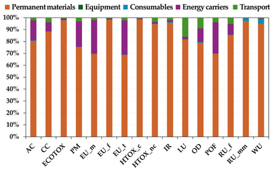
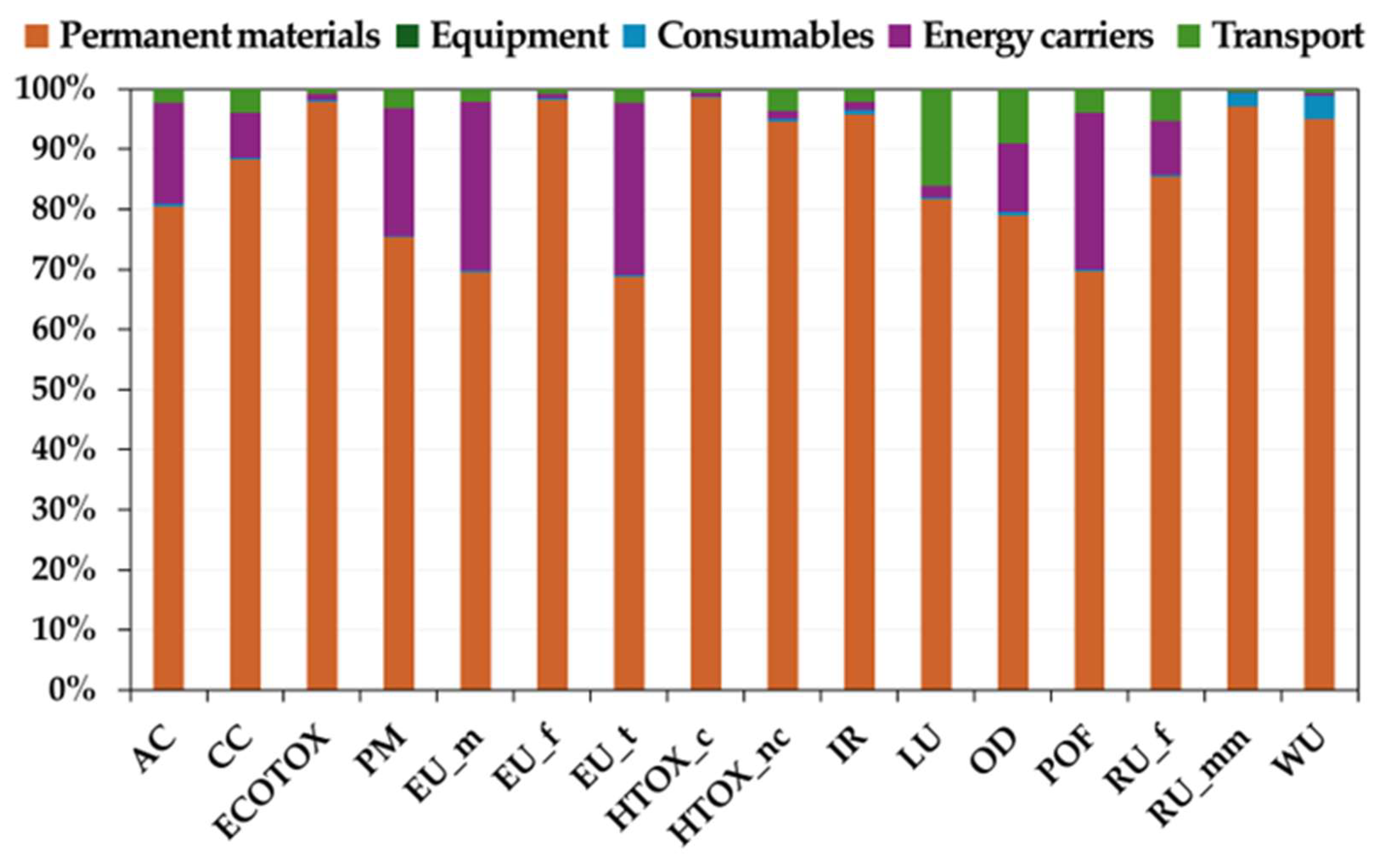
Environmental impact characterization results of the coaxial probe installation, obtained using the Environmental Footprint 3.1 method, are reported in Figure 1 and Table S26. The corresponding single score results are presented in Figure S4. The results show that the most impactful process unit across all impact categories is the “Permanent materials”, followed by the “Energy carriers”. In contrast, the remaining PUs show low impacts across all categories. The process contribution analysis shows that the main impact driver is the steel input, accounting for 41% of the total impact, followed by hot-dip galvanization, which accounts for 30% (Figure S5).
Figure 1.
Life cycle contribution analysis of characterized results for the geothermal coaxial probe installation (EF 3.1 method; FU: installation of one geothermal coaxial probe, 80 m in length, in the typical alluvial sediments of the Venetian Po Valley).
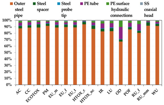
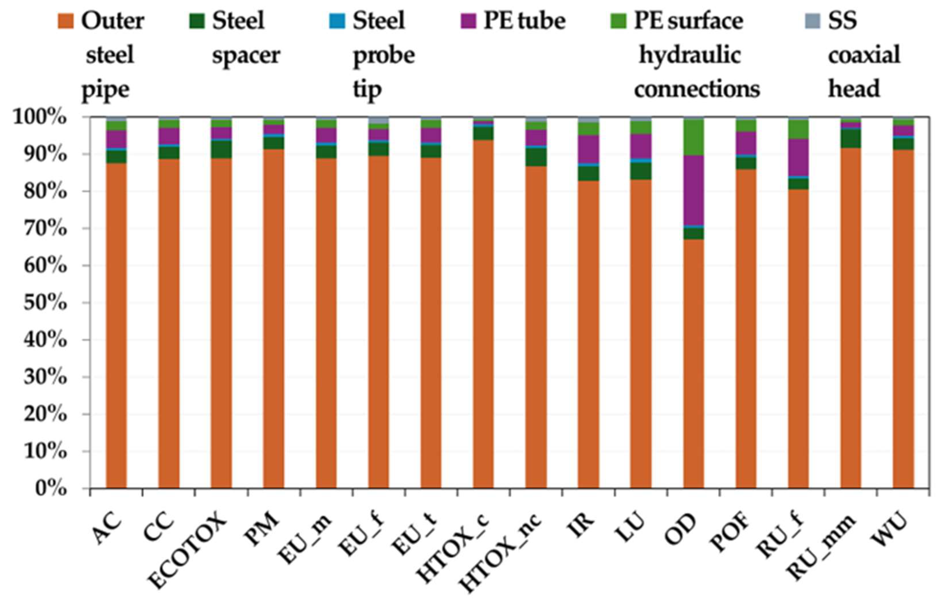
Focusing on the “Permanent materials” process unit, Figure 2 demonstrates that the “Outer steel pipe” is the main contributor to the overall environmental impact, accounting on average for approximately 87% of the total characterized impacts across all impact categories. Table S27 reports the corresponding characterized values.
Figure 2.
Life cycle contribution analysis of characterized results of the “Permanent materials” process unit (EF 3.1 method).
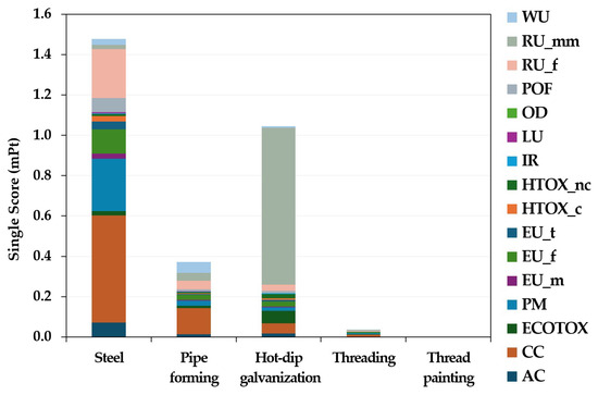
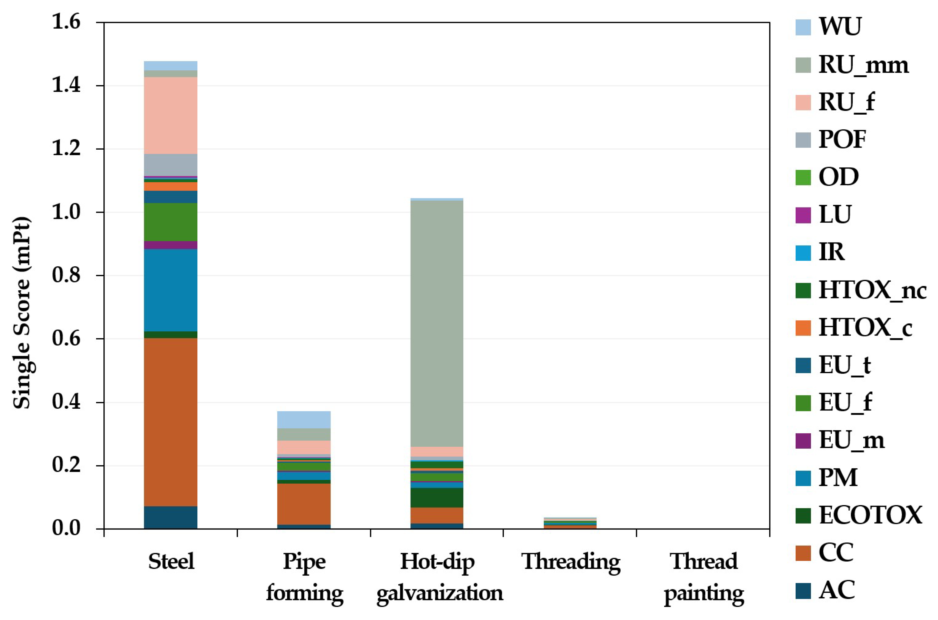
The single score results (after normalization and weighting) of the “Outer steel pipe” component (Figure 3) further break down the specific contributions of each input within this unit. Notably, the quantity of steel required for the outer pipe production represented the most significant contribution, accounting for 50% of the total impact, followed by the zinc coating process, which accounts for 36%. In contrast, the pipe-forming and thread-cutting processes exhibit lower environmental burdens compared to the raw material requirements and the hot-dip galvanization process, contributing 13% and 1% of the “Outer steel pipe” impact, respectively. Finally, the impact of the resin coating applied to the threaded section is negligible, due to the minimal quantity of material used.
Figure 3.
Single score of the characterized results, after normalization and weighting, of the “Outer steel pipe—2 m in length” component (EF 3.1 method).
Figure 3 and Table S28 show that regarding the contribution of steel as a raw material, the main impact categories affected involve “climate change”, followed by “resource use, fossils”, and “particulate matter”. These results are directly linked to the thermodynamic and chemical nature of steel production processes. The hot-dip galvanization process mainly affects the “resource use, minerals and metals” impact category, related to zinc production processes and to the high temperatures required in galvanic processes, characterized by high energy demand. Overall, the most relevant impact categories for the “Outer steel pipe” component are “resource use, minerals and metals” (29%) and “climate change” (25%).
Figure 4 presents the comparative life cycle contribution analysis for the installation of both the next-generation coaxial probes and the conventional double U-tube probes. As defined in the Section 2.2.1, and in accordance with established literature benchmarks [20,21,22], the performance of the two systems was normalized on the basis that the 80 m coaxial probe achieved a heat exchange rate equivalent to a 100 m double U-tube probe [20,21,22]. This 20% length reduction was accounted for in the comparative sustainability assessment. Results focusing exclusively on the conventional double U-tube installation process are reported in the Supplementary Materials (Figures S6 and S7, and Table S29).
Figure 4.
Comparison of life cycle contribution analysis of characterized results for coaxial and conventional double U-tube probe installations (EF 3.1 method; FU: installation of one geothermal coaxial probe 80 m in length or one conventional double U-tube probe 100 m in length, in the typical alluvial sediments of the Venetian Po Valley).
The comparative LCA (Figure 4 and Table S30) revealed that the coaxial configuration was characterized by a greater burden on “resource use, minerals and metals”, “human toxicity, cancer”, “human toxicity, non-cancer”, and “ecotoxicity, freshwater”. Additionally, this installation type showed a high impact in the “water use” category, as well as in “eutrophication, freshwater”. Conversely, the double U-tube probe installation exhibited higher environmental impacts across the remaining impact categories.
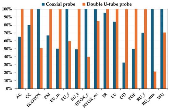
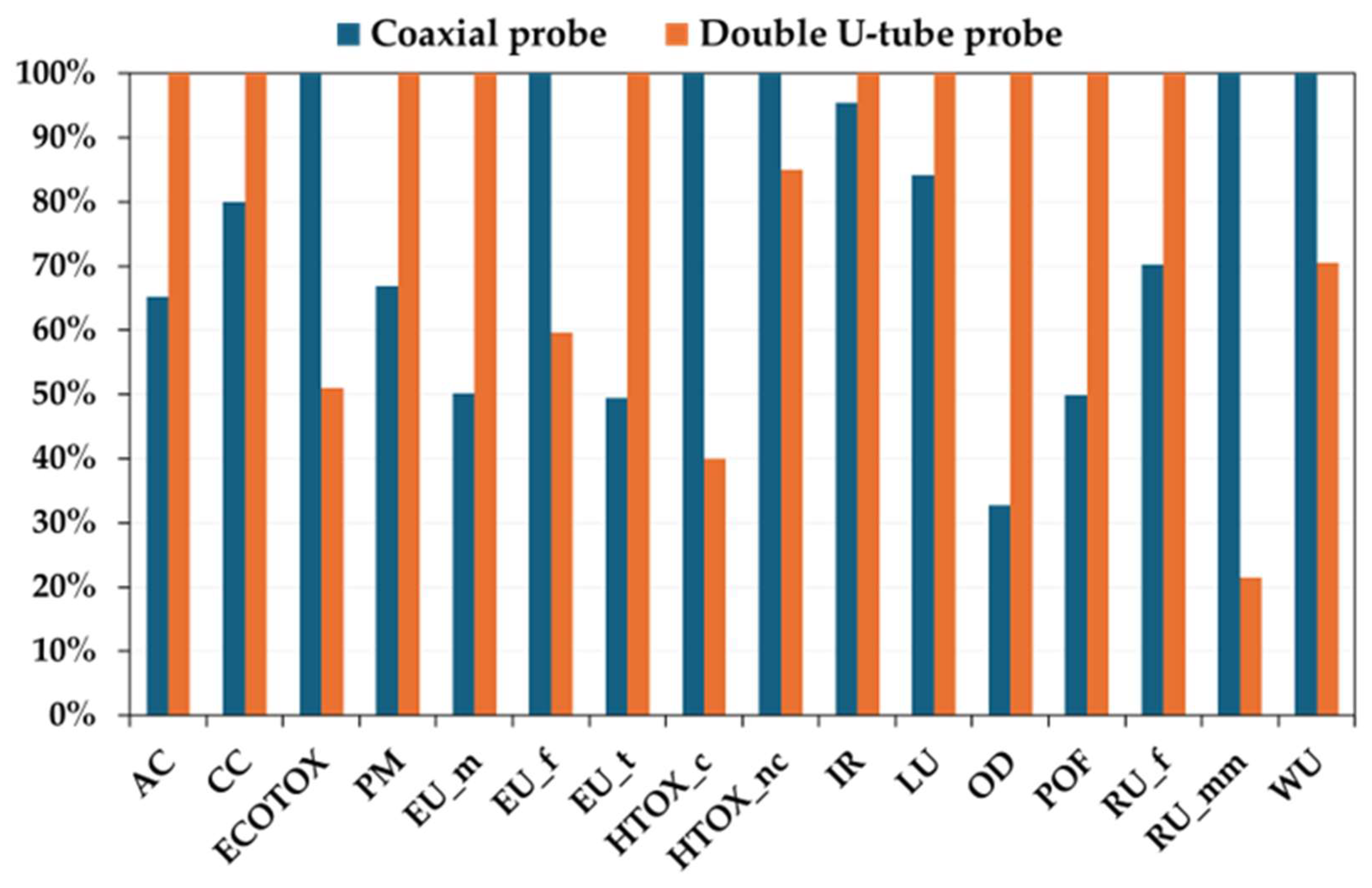
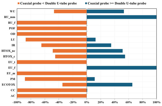
Discernibility analysis was employed to evaluate the uncertainties inherent in the comparative LCA, facilitating a statistically significant distinction between the two installation processes [37,38]. To ensure a robust assessment, this analysis utilized 1000 Monte Carlo iterations, accounting for the probabilistic variability. Uncertainty was applied only to background (Ecoinvent) datasets, while primary inventory data were treated as deterministic (i.e., fixed values). By replacing fixed values with probability distributions, Monte Carlo simulation enables the assessment of the statistical significance of the environmental advantages of one process over the alternative. As shown in Figure 5, the frequency of Monte Carlo outcomes indicated which installation process yields a higher impact score across each impact category. An outcome frequency approaching 100% (positive or negative) denotes a statistically significant difference, allowing for a comparison with high confidence and suggesting high data quality. In contrast, when probability distributions significantly overlap, the lower discernibility frequencies indicate that the environmental performances of the two options are statistically indistinguishable [37,38]. Figure 5 shows that, unlike the outcomes of Figure 4, for many impact categories, the coaxial and double U-tube probe installation options exhibit comparable environmental performances. In particular, the higher impact of the coaxial system was confirmed for “resource use, minerals and metals” and “eutrophication, freshwater”. Similarly, the double U-tube higher burden is robustly verified for “resource use, fossils”, “photochemical ozone formation”, “ozone depletion”, “eutrophication, terrestrial”, “eutrophication, marine”, and “acidification”. For the remaining impact categories, the differences between the two configurations were limited and not statistically significant, suggesting that the two technologies can be considered environmentally equivalent in those specific areas. Furthermore, it should be noted that the impact categories “water use”, “human toxicity, non-cancer”, “human toxicity, cancer”, and “freshwater ecotoxicity” do not show statistically significant differences; any potential differences may be masked by their intrinsically high uncertainty, as well as by the well-known methodological limitations associated with these indicators [39].
Figure 5.
Comparison of the characterized impact results between the coaxial and the conventional double U-tube probe installations, for each impact category, derived from 1000 Monte Carlo simulations—95% confidence interval (EF 3.1 method; FU: installation of one geothermal coaxial probe 80 m in length or one conventional double U-tube probe 100 m in length, in the typical alluvial sediments of the Venetian Po Valley). A frequency of outcomes close to 100% (either positive or negative) indicates a statistically significant difference, enabling a high-confidence comparison and reflecting good data quality.
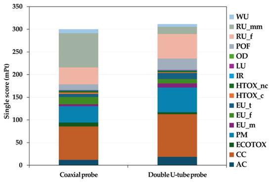
The comparison of the single score results, obtained after normalization and weighting, for the coaxial probe installation and the double U-tube probe installation (Figure 6, Table S31), showed a slightly higher overall impact for the double U-tube installation, with a single score of 312 mPt, compared to 300 mPt for the coaxial configuration. This very small difference (about 4%), together with the uncertainty results, confirms that the impacts of manufacturing and installation phases are substantially the same for the two technologies compared.
Figure 6.
Comparison of the single score of the characterized results, after normalization and weighting, for coaxial and conventional double U-tube probe installations (EF 3.1 method; FU: installation of one geothermal coaxial probe 80 m in length or one conventional double U-tube probe 100 m in length, in the typical alluvial sediments of the Venetian Po Valley).
As previously illustrated in Figure 2 and Figure 3, the environmental profile of the coaxial probe was primarily driven by the permanent materials (steel and hot-dip galvanization) used in its construction, which mainly affect the “resource use, minerals and metals” and “climate change” categories (Table S31). In contrast, the double U-tube impact assessment showed that the more impactful processes are drilling-related diesel use and installation activities, and “climate change” and “resource use, fossils” are the dominant categories, again mainly related to permanent materials PU (Table S31).
4. Discussion
On the basis of life cycle impact assessment results obtained, and with the aim of reducing the overall environmental impact of the under-development coaxial probe, different mitigation strategies are proposed here through a sensitivity analysis, to provide useful recommendations for eco-design.
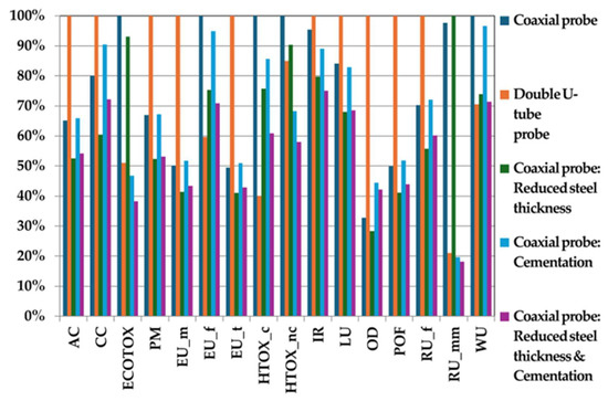
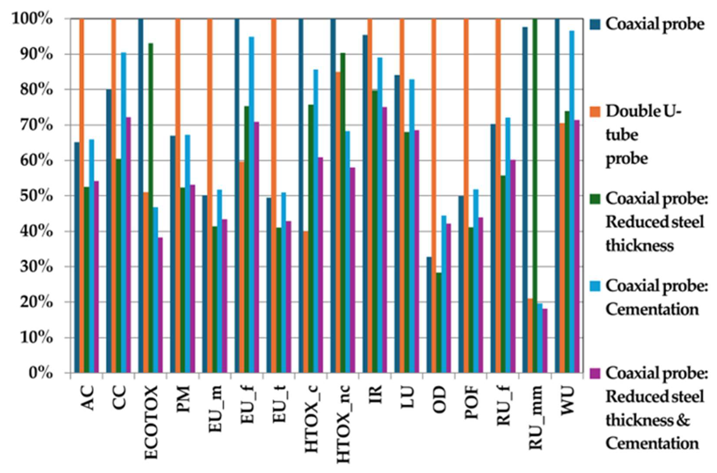
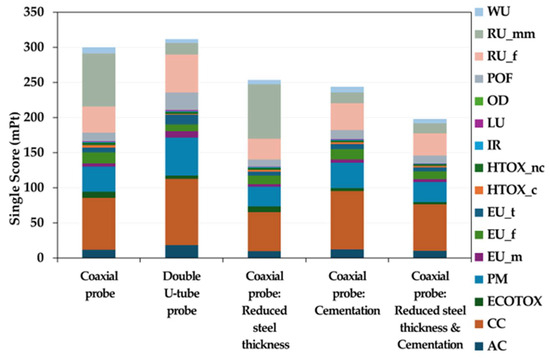
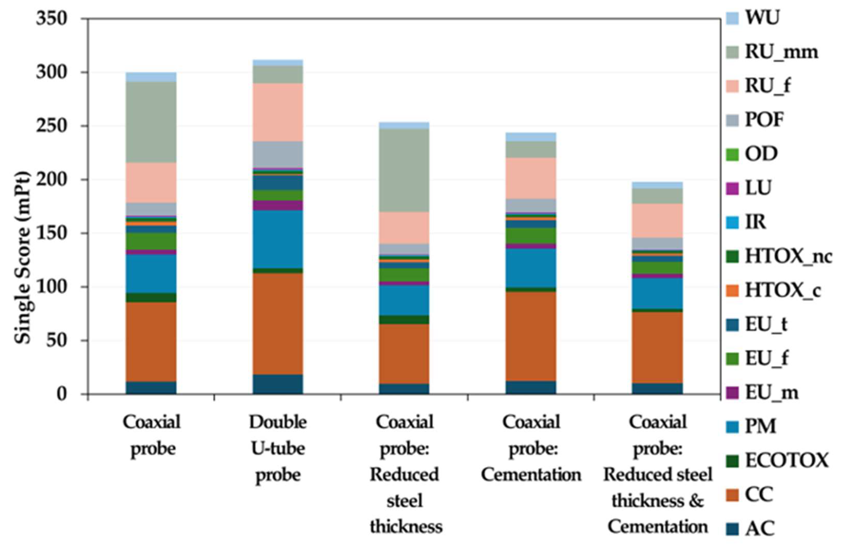
First of all, as shown in Figure 2 and Figure 3 and Table S28, due to the high impact related to steel input (40% of the total impact), mainly related to the outer steel tube, the possibility of reducing its thickness is evaluated. The structural characteristics required to maintain the mechanical and hydraulic properties of this pipe under the specific geomorphological conditions and for geothermal applications are defined in consultation with engineering and installation experts, enabling the assessment of a plausible thickness reduction from 8 mm to 5 mm. This implies a decrease in the pipe linear weight, from 10.26 kg/m to 6.78 kg/m, resulting in a final configuration with an external diameter of 60 mm and an internal diameter of 50 mm. The results in terms of environmental impact of this steel pipe thickness reduction are reported in Figure 7, Table S30 and Figure 8, compared with the original coaxial probe and the conventional double U-tube configuration. Overall, the proposed strategy may lead to a reduction in the total environmental footprint, making this new configuration with a reduced steel amount more advantageous than both the original coaxial design and the conventional double U-tube configuration (Figure 7 and Figure 8). The single score results indicate a 15% reduction in environmental impact with respect to the coaxial probe installation. Impact categories closely linked to steel consumption, such as “climate change” and “particulate matter” show a decrease in the thinner configuration. Conversely, the “resource use, minerals and metals” category possesses a slight increase due to the zinc coating process; specifically, the reduction in wall thickness results in a larger internal surface area requiring galvanization.
Figure 7.
Comparison of the life cycle contribution analysis of the characterized results for coaxial and conventional double U-tube probe installations. The figure also illustrates the proposed strategies to reduce the environmental burden of the coaxial configuration, such as reducing the thickness of the outer steel pipe and grouting, alongside the cumulative impact of these mitigation strategies (EF 3.1 method; FU: installation of one geothermal coaxial probe 80 m in length or one conventional double U-tube probe 100 m in length, in the typical alluvial sediments of the Venetian Po Valley).
Figure 8.
Comparison of the single score of the characterized results, after normalization and weighting, for coaxial and conventional double U-tube probe installations. The figure also illustrates the proposed strategies to reduce the environmental burden of the coaxial configuration, such as reducing the thickness of the outer steel pipe and grouting, alongside the cumulative impact of these mitigation strategies (EF 3.1 method; FU: installation of one geothermal coaxial probe 80 m in length or one conventional double U-tube probe 100 m in length, in the typical alluvial sediments of the Venetian Po Valley).
Other possibilities are also evaluated to reduce the overall environmental impact of the coaxial probe installation process. A mechanically and structurally feasible solution involves the application of wall grouting even for coaxial probe installations. This approach would eliminate the need for hot-dip galvanization of the outer pipe, a process identified as having a significant environmental impact (30% of the total impact of the coaxial probe). The amount of grouting material is calculated based on the borehole diameter necessary for the coaxial probe installation. The results, with a single score reduction of 19% compared to the coaxial probe configuration (Figure 8), indicate that this solution represents the most effective approach proposed to date, mainly driven by a significant reduction of “resource use, minerals and metals” category (0.0128 Kg Sb eq versus 0.0637 Kg Sb eq of the coaxial probe configuration). Conversely, the addition of the cement grout increases the “climate change” impact; consequently, compared to the coaxial configuration, this category increases from 2.63 × 10³ kg CO2 eq to 2.99 × 10³ kg CO2 eq.
A final sensitivity analysis is performed by combining both mitigation strategies. The results demonstrate a decrease across all impact categories, yielding the overall best performance among the studied configurations, with a 34% reduction in total environmental impact with respect to the original coaxial probe installation.
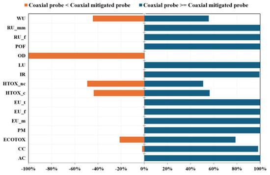
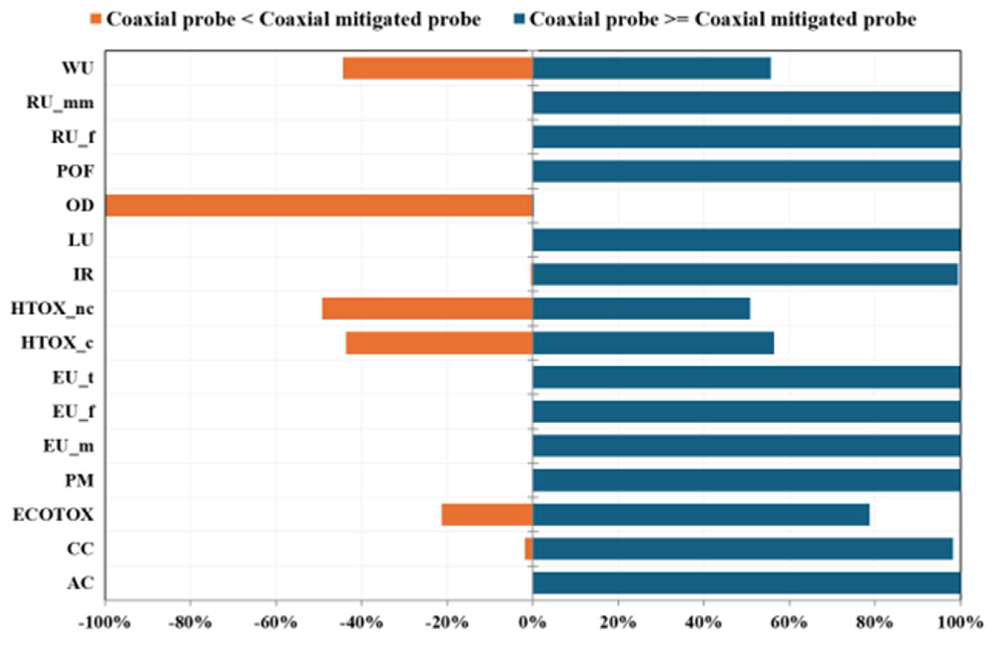
Similarly to the comparison between the coaxial probe and the double U-tube configurations, a Monte Carlo simulation (1000 iterations; 95% confidence interval) was performed to assess the statistical significance of the differences shown in Figure 7 and Figure 8. As illustrated in Figure 9, for many impact categories, the mitigated coaxial probe achieves significantly lower impacts across most categories. Conversely, the “ozone depletion” category exhibits higher impacts for the mitigated probe, a result primarily attributed to the grouting required for structural feasibility and to avoid the hot-dip galvanization of the outer pipe. In contrast, the categories of “water use”, “human toxicity, non-cancer”, “human toxicity, cancer”, and “ecotoxicity, freshwater” do not show statistically significant differences; this may be attributed to their intrinsically high data uncertainty and to the methodological limitations associated with these impact categories, whose characterization factors remain at the lowest recommendation levels within the EF framework [39].
Figure 9.
Comparison of the characterized impact results between the standard coaxial probe and the mitigated probe configurations (with reduced outer steel pipe thickness and grouting), for each impact category, derived from 1000 Monte Carlo simulations—95% confidence interval (EF 3.1 method; FU: installation of one geothermal coaxial probe 80 m in length or one mitigated coaxial probe 80 m in length, in the typical alluvial sediments of the Venetian Po Valley). A frequency of outcomes close to 100% (either positive or negative) indicates a statistically significant difference, enabling a high-confidence comparison and reflecting good data quality.
Referring to literature indications, the most important impact categories to evaluate in the environmental impact of geothermal plants are: “acidification”, “climate change”, “human toxicity, cancer”, “human toxicity, non-cancer”, “resource use, minerals and metals”, “resource use, fossils”, and “ecotoxicity freshwater” [26,32]. This study shows that (Table S31) the optimized coaxial probe installation, with reduced outer steel pipe thickness and the use of grouting wall, results in a reduction in the “acidification” category by 17%, “climate change” category by 10%, and “resource use, fossils” category by 14%. Notable reductions are obtained for “human toxicity, cancer” (39%), “human toxicity, non-cancer” (42%), “ecotoxicity freshwater” (62%), and “resource use, minerals and metals” (81%, mainly related to the avoided hot-dip galvanization in the optimized coaxial probe).
The environmental impact of the next-generation coaxial probe installation process, encompassing raw material extraction and manufacturing, equipment and land use, should ideally be scaled not only to the probe energy output but also to the system operational lifespan and its cost-effectiveness, as suggested by the literature reports for similar geothermal systems [21,22]. Although the results discussed in this section provide interesting results for improving the eco-design of coaxial processes, several methodological and practical limitations should be highlighted. The primary limitation of this study stems from the defined system boundaries, which are strictly restricted to the manufacturing and installation phases. The operational phase and the end-of-life management were excluded from the assessment. Consequently, this cradle-to-installation scope prevents a comprehensive, full-lifecycle evaluation, making it impossible to definitively determine which technology performs better over the long term. This boundary selection is directly tied to the fact that this coaxial probe technology is still under development; as a result, real-world inventory data regarding operational performance, actual service life, maintenance requirements, and lifespan evaluation are currently unavailable. In addition, the findings are strongly bound to the specific local conditions of the case study. The inventory and modeling reflect the geological and geomorphological context of the Venetian Po Valley (Padua, Italy). Therefore, the environmental profiles and comparative advantages identified here could significantly shift in different geological settings, such as hard rock formations or dry unsaturated soils. Moreover, a major source of uncertainty lies in the assumption of thermal equivalence between the systems. In this study, an 80 m coaxial probe was assumed to provide a thermal yield equivalent to a 100 m conventional double U-tube borehole heat exchanger. While this assumption is rooted in existing literature [22,40,41], it is not backed by site-specific experimental testing. As the thermal exchange is heavily site-dependent, this assumption could introduce uncertainty into the comparative results, particularly regarding the actual drilling lengths required in practice. While acknowledging that the absolute environmental results depend on local conditions, the primary data collection methodology and the inventory model developed herein offer a highly replicable framework for evaluating and comparing similar SGE technologies worldwide. Finally, certain minor system components and infrastructure flows were excluded from the product system. Specifically, the environmental burdens associated with the manufacturing of drilling machinery and the maintenance of construction equipment were omitted. Although these cut-offs are common practice in preliminary LCAs, their exclusion might introduce a slight underestimation of the total cradle-to-installation environmental footprint.
5. Conclusions
This study evaluated the environmental impact of installing innovative coaxial geothermal probes (currently under development), by means of a detailed Life Cycle Assessment, using primary data from a real-scale installation conducted at the National Research Council in Padova (Italy). The results were compared against the environmental burdens associated with the installation of conventional double U-tube probes within the same geomorphological setting. The system boundaries encompassed the probe manufacturing, the installation phase, and the waste management for each probe design. Furthermore, several sensitivity analyses were performed to identify pathways for minimizing the overall environmental footprint of next-generation coaxial configurations.
Our findings illustrate that material selection and manufacturing processes were critical drivers of the environmental performance of geothermal plants. Consequently, accounting only for raw material impacts while neglecting industrial processing yields a partial assessment, which significantly underestimates the total environmental impact of geothermal facilities.
This work demonstrates that LCA is an essential tool not only for providing a comprehensive impact profile but also for identifying critical hotspots and supporting eco-design strategies during advanced stages of technological development.
In conclusion, this work offers a significant methodological contribution by defining the detailed life cycle inventory framework required to assess the sustainability and environmental impact of a shallow geothermal plant. Although the final impact scores are site-specific, the structured approach to primary data collection and the inventory architecture developed here are robust and transferable, offering a reliable reference for benchmarking similar SGE systems worldwide.
Supplementary Materials
The following supporting information can be downloaded at: https://www.mdpi.com/article/10.3390/cleantechnol8040116/s1. Figure S1. A detailed image of the double U-tube probe (left) and the coaxial probe investigated in the present manuscript. Figure S2. Cradle-to-gate system boundary for the manufacturing and installation of one geothermal coaxial probe, 80 m in length, in the typical alluvial sediments of the Venetian Po Valley. Operation and end-of-life stages were excluded from the system boundaries. Figure S3. Cradle-to-gate system boundary for the manufacturing and installation of one conventional geothermal double U-tube probe, 100 m in length, in the typical alluvial sediments of the Venetian Po Valley. Operation and end-of-life stages were excluded from the system boundaries. Table S1. Life cycle inventory of the “Permanent materials” PU for the installation of one geothermal coaxial probe, 80 m in length, in the typical alluvial sediments of the Venetian Po Valley. Tables S2. Life cycle inventory of the “Outer steel pipe” component. Tables S3. Life cycle inventory of the “Steel spacer” component. Table S4. Life cycle inventory of the “Steel probe tip” component. Table S5. Life cycle inventory of the “PE Tube” component. Table S6. Life cycle inventory of the “PE surface hydraulic connection” component. Table S7. Life cycle inventory of the “Stainless steel coaxial head” component. Table S8. Life cycle inventory of the “Permanent materials” PU for the installation of one geothermal conventional double U-tube probe, 100 m in length, in the typical alluvial sediments of the Venetian Po Valley. Table S9. Life cycle inventory of the “PE double U-tube” component. Table S10. Life cycle inventory of the “PE spacer” component. Table S11. Life cycle inventory of the “PE lower cap” component. Table S12. Life cycle inventory of the “Steel weight” component. Table S13. Life cycle inventory of the “PE grout injection pipe” component. Table S14. Life cycle inventory of the “Grout material” component. Table S15. Life cycle inventory of “PE surface heat” component. Table S16. Life cycle inventory of the “Surface hydraulic connection” component. Table S17. Life cycle inventory of the “Equipment” PU for the installation of one geothermal coaxial probe, 80 m in length, in the typical alluvial sediments of the Venetian Po Valley. Table S18. Life cycle inventory of the “Equipment” PU for the installation of one geothermal conventional double U-tube probe, 100 m in length, in the typical alluvial sediments of the Venetian Po Valley. Table S19. Life cycle inventory of the “Wear parts” PU for the installation of one geothermal conventional double U-tube probe, 100 m in length, in the typical alluvial sediments of the Venetian Po Valley. Table S20. Life cycle inventory of the “Consumables” PU for the installation of one geothermal coaxial probe, 80 m in length, in the typical alluvial sediments of the Venetian Po Valley. Table S21. Life cycle inventory of the “Consumables” PU for the installation of one geothermal conventional double U-tube probe, 100 m in length, in the typical alluvial sediments of the Venetian Po Valley. Table S22. Life cycle inventory of the “Energy carriers” PU for the installation of one geothermal coaxial probe, 80 m in length, in the typical alluvial sediments of the Venetian Po Valley. Table S23. Life cycle inventory of the “Energy carriers” PU for the installation of one geothermal conventional double U-tube probe, 100 m in length, in the typical alluvial sediments of the Venetian Po Valley. Table S24. Life cycle inventory of the “Transport” PU for the installation of one geothermal coaxial probe, 80 m in length, in the typical alluvial sediments of the Venetian Po Valley. Table S25. Life cycle inventory of the “Transport” PU for the installation of one geothermal conventional double U-tube probe, 100 m in length, in the typical alluvial sediments of the Venetian Po Valley. Table S26. Characterized impact results for one geothermal coaxial probe installation (EF 3.1 method; FU: installation of one geothermal coaxial probe, 80 m in length, in the typical alluvial sediments of the Venetian Po Valley). Figure S4. Single score of the characterized results, after normalization and weighting, for the geothermal coaxial probe installation (EF 3.1 method; FU: installation of one geothermal coaxial probe, 80 m in length, in the typical alluvial sediments of the Venetian Po Valley). Figure S5. Geothermal coaxial probe process contribution (EF 3.1 method; FU: installation of one geothermal coaxial probe, 80 m in length, in the typical alluvial sediments of the Venetian Po Valley). Cut-off: 0.5%. Table S27. Characterized impact results for the “Permanent materials” process unit for one geothermal coaxial probe installation (EF 3.1 method). Figure S6. Life cycle contribution analysis of characterized results for the geothermal conventional double U-tube probe installation (EF 3.1 method; FU: installation of one conventional double U-tube probe, 100 m in length, in the typical alluvial sediments of the Venetian Po Valley). Table S28. Single score of the “Outer steel pipe” component (EF 3.1 method). The dimensionless unit mPt stands for milliPoints, unit of the weighted results. Table S29. Characterized impact results for the conventional geothermal double U-tube probe installation (EF 3.1 method; FU: installation of one double U-tube probe, 100 m in length, in the typical alluvial sediments of the Venetian Po Valley). Figure S7. Single score of the characterized results, after normalization and weighting, for the conventional geothermal double U-tube probe installation (EF 3.1 method; FU: installation of one double U-tube probe, 100 m in length, in the typical alluvial sediments of the Venetian Po Valley). Table S30. Characterized impact results of the comparison of coaxial and conventional double U-tube probe installations. The proposed strategies to reduce the environmental burden of the coaxial configuration, such as reducing the thickness of the outer steel pipe and grouting, alongside the cumulative impact of these mitigation strategies are also reported (EF 3.1 method; FU: installation of one geothermal coaxial probe 80 m in length or one conventional double U-tube probe 100 m in length, in the typical alluvial sediments of the Venetian Po Valley). Table S31. Single score results of coaxial and conventional double U-tube probe installations. The proposed strategies to reduce the environmental burden of the coaxial configuration, such as reducing the thickness of the outer steel pipe and grouting, alongside the cumulative impact of these mitigation strategies are also reported (EF 3.1 method; FU: installation of one geothermal coaxial probe 80 m in length or one conventional double U-tube probe 100 m in length, in the typical alluvial sediments of the Venetian Po Valley) The dimensionless unit mPt stands for milliPoints, unit of the weighted results.
Author Contributions
Conceptualization, S.F., F.V. and S.B.; methodology, S.F. and F.V.; investigation, S.F., F.V., N.M. and S.B.; data curation, S.F. and F.V.; writing—original draft preparation, S.F. and F.V.; writing—review and editing, S.B., A.B. (Alessandro Bortolin), A.B. (Adriana Bernardi), N.M., M.F., M.L. and L.P.; visualization, S.F., F.V. and S.B.; funding acquisition M.F., M.L. and L.P.; supervision, M.F., L.P. and M.L.; S.F. and F.V. contributed equally to this work. All authors have read and agreed to the published version of the manuscript.
Funding
This research was funded by the SINERGHY project (Project Code 24729_002238, DGR 729/2024) funded by the Veneto Region.
Data Availability Statement
The original contributions presented in this study are included in this article and the Supplementary Materials. Further inquiries can be directed to the corresponding author.
Acknowledgments
During the preparation of this work the authors used Gemini 2.5 Flash to improve the quality and clarity of English language of some manuscript parts. After using this tool, the authors reviewed and edited the content as needed and take full responsibility for the content of the published article.
Conflicts of Interest
Author Adriana Bernardi, Nicola Mutinelli and Luc Pockelè were employed by the company RED Srl. All authors declare that the research was conducted in the absence of any commercial or financial relationships that could be construed as a potential conflict of interest.
Abbreviations
The following abbreviations are used in this manuscript:
| LCA | Life Cycle Assessments |
| GHG | GreenHouse Gas |
| HPs | Heat Pumps |
| ASHPs | Air-Source Heat Pumps |
| GSHPs | Ground-Source Heat Pumps |
| BHE | Borehole Heat Exchanger |
| SGE | Shallow Geothermal Energy |
| GWP | Global Warming Potential |
| FU | Functional Unit |
| LCI | Life Cycle Inventory |
| LCIA | Life Cycle Impact Assessment |
| PE | Polyethylene |
| TSTs | Thermal Response Tests |
| EF | Environmental Footprint |
| AC | Acidification |
| CC | Climate change |
| ECOTOX | Ecotoxicity, freshwater |
| PM | Particulate matter |
| EU_m | Eutrophication, marine |
| EU_f | Eutrophication, freshwater |
| EU_t | Eutrophication, terrestrial |
| HTOX_c | Human toxicity, cancer |
| HTOX_nc | Human toxicity, non-cancer |
| IR | Ionizing radiation |
| LU | Land use |
| OD | Ozone depletion |
| POF | Photochemical ozone formation |
| RU_f | Resource use, fossils |
| RU_mm | Resource use, minerals and metals |
| WU | Water use |
| PUs | Process Units |
| SS | Stainless-steel |
References
- European Environmental Agency. Total Net GHG Emissions in the EU (1990–2050). Available online: https://www.eea.europa.eu/en/analysis/publications/trends-and-projections-in-europe-2025/total-net-ghg-emissions (accessed on 14 May 2026).
- International Energy Agency. Renewables 2025. Available online: https://www.iea.org/reports/renewables-2025 (accessed on 14 May 2026).
- Lund, J.W.; Toth, A.N. Direct Utilization of Geothermal Energy 2020 Worldwide Review. Geothermics 2021, 90, 101915. [Google Scholar] [CrossRef] [Scilit]
- Menberg, K.; Hemmerle, H.; Bayer, P.; Bott, C.; Bidarmaghz, A.; Ferguson, G.; Bloemendal, M.; Blum, P. Opportunities, Benefits and Impacts of Shallow Geothermal Energy. Nat. Rev. Earth Environ. 2025, 6, 808–823. [Google Scholar] [CrossRef] [Scilit]
- International Energy Agency. The Future of Heat Pumps. Available online: https://www.iea.org/reports/the-future-of-heat-pumps (accessed on 14 May 2026).
- Sliwa, T.; Sapińska-Śliwa, A.; Gonet, A.; Kowalski, T.; Sojczyńska, A. Geothermal Boreholes in Poland-Overview of the Current State of Knowledge. Energies 2021, 14, 3251. [Google Scholar] [CrossRef] [Scilit]
- Pratiwi, A.S.; Trutnevyte, E. Life Cycle Assessment of Shallow to Medium-Depth Geothermal Heating and Cooling Networks in the State of Geneva. Geothermics 2021, 90, 101988. [Google Scholar] [CrossRef] [Scilit]
- Ahmed, A.A.; Assadi, M.; Kalantar, A.; Sliwa, T.; Sapińska-Śliwa, A. A Critical Review on the Use of Shallow Geothermal Energy Systems for Heating and Cooling Purposes. Energies 2022, 15, 4281. [Google Scholar] [CrossRef] [Scilit]
- ISO 14044:2006; Environmental Management—Life Cycle Assessment—Requirements and Guidelines for the Life Cycle Inventory Analysis. International Organization for Standardization (ISO): Geneva, Switzerland, 2006.
- ISO 14040:2006; Environmental Management—Life Cycle Assessment—Principles and Framework. International Organization for Standardization (ISO): Geneva, Switzerland, 2006.
- Parisi, M.L.; Douziech, M.; Tosti, L.; Pérez-López, P.; Mendecka, B.; Ulgiati, S.; Fiaschi, D.; Manfrida, G.; Blanc, I. Definition of LCA Guidelines in the Geothermal Sector to Enhance Result Comparability. Energies 2020, 13, 3534. [Google Scholar] [CrossRef] [Scilit]
- Tomasini-Montenegro, C.; Santoyo-Castelazo, E.; Gujba, H.; Romero, R.J.; Santoyo, E. Life Cycle Assessment of Geothermal Power Generation Technologies: An Updated Review. Appl. Therm. Eng. 2017, 114, 1119–1136. [Google Scholar] [CrossRef] [Scilit]
- Liu, G.; Song, J.; Zhang, W.; Cao, Q.; Yang, W.; Jiang, Z. Environmental Footprints of Global Geothermal Power: Bridging Micro-Level Technological and Macro-Level National Assessments. Energy Convers. Manag. 2026, 349, 120853. [Google Scholar] [CrossRef] [Scilit]
- Kaczmarczyk, M.; Tomaszewska, B.; Kabay, N. Sustainable Geothermal Water Treatment with Ultrafiltration and Reverse Osmosis: A Life Cycle Assessment Perspective. Water Resour. Ind. 2026, 35, 100337. [Google Scholar] [CrossRef] [Scilit]
- Bayer, P.; Rybach, L.; Blum, P.; Brauchler, R. Review on Life Cycle Environmental Effects of Geothermal Power Generation. Renew. Sustain. Energy Rev. 2013, 26, 446–463. [Google Scholar] [CrossRef] [Scilit]
- Kaczmarczyk, M.; Sowiżdżał, A.; Tomaszewska, B. Life Cycle and Water Footprint Assessment in the Geothermal Energy Sector. Energies 2024, 17, 6050. [Google Scholar] [CrossRef] [Scilit]
- Deng, Y.; Yao, Z.; Chen, M.; Hu, Y.J. Assessment of the Development Potential of Shallow Geothermal Energy Heating and Cooling Projects in Southern China Based on Whole-Lifecycle Methodology. Energies 2025, 18, 2200. [Google Scholar] [CrossRef] [Scilit]
- Milousi, M.; Pappas, A.; Vouros, A.P.; Mihalakakou, G.; Souliotis, M.; Papaefthimiou, S. Evaluating the Technical and Environmental Capabilities of Geothermal Systems through Life Cycle Assessment. Energies 2022, 15, 5673. [Google Scholar] [CrossRef] [Scilit]
- Righinui, D. I.L.L.A.P. Brevetto d’Invenzione—Procedimento e Dispositivo Di Installazione Nel Sottosuolo Di Sonda Geotermica Coassiale 2020. Available online: https://scispace.com/papers/procedimento-e-dispositivo-di-installazione-nel-sottosuolo-15ohauyog (accessed on 10 May 2026).
- Pockele, L.; Mezzasalma, G.; Righini, D.; Vercruysse, J.; Cicolin, F.; Cadelano, G.; Galgaro, A.; Dalla Santa, G.; Carli, M.D.E.; Emmi, G.; et al. Innovative Coaxial Heat Exchangers for Shallow Geothermal. In Proceedings of the World Geothermal Congress 2020+1, Reykjavik, Iceland, 21–26 May 2021. [Google Scholar]
- GEO4CIVHIC Project. GA 792355. Deliverable D7.2. Cost-Effectiveness Demonstration. 2022. Available online: https://geo4civhic.eu/wp-deliverables/ (accessed on 15 May 2026).
- Cheap-GSHPs Project. GA 657982 Deliverable D8.5. Life Cycle Cost Analysis of GSHE Developed Versus State of Art. 2018. Available online: https://cheap-gshp.eu/ (accessed on 15 May 2026).
- Zampori, L.; Pant, R. Suggestions for Updating the Product Environmental Footprint (PEF) Method; JRC Technical Reports; Publications Office of the European Union: Luxembourg, 2019; p. 76. [Google Scholar]
- European Commission. Commission Recommendation on the Use of the Environmental Footprint Methods; European Commission: Brussels, Belgium, 2021. [Google Scholar]
- PRé Sustainability. SimaPro Database Manual—Methods Library; PRé Sustainability: Amersfoort, The Netherlands, 2025. [Google Scholar]
- Zuffi, C.; Manfrida, G.; Asdrubali, F.; Talluri, L. Life Cycle Assessment of Geothermal Power Plants: A Comparison with Other Energy Conversion Technologies. Geothermics 2022, 104, 102434. [Google Scholar] [CrossRef] [Scilit]
- Liang, C.; Schalbart, P.; Roux, C.; Peuportier, B. Enhancing Life Cycle Assessment for Reversible Ground-Coupled Heat Pump Systems through Dynamic Analysis. J. Clean. Prod. 2024, 472, 143498. [Google Scholar] [CrossRef] [Scilit]
- Bartolozzi, I.; Rizzi, F.; Frey, M. Are District Heating Systems and Renewable Energy Sources Always an Environmental Win-Win Solution? A Life Cycle Assessment Case Study in Tuscany, Italy. Renew. Sustain. Energy Rev. 2017, 80, 408–420. [Google Scholar] [CrossRef] [Scilit]
- De Rose, A.; Harcouët-Menou, V.; Laenen, B.; Caia, V.; Facco, L.; Guglielmetti, L.; Olivieri, N.; Rocco, E.; Strazza, C.; Vela, S.; et al. Study on “Geothermal Plants” and Applications’ Emissions: Overview and Analysis—Final Report; Publications Office of the European Union: Luxembourg, 2020. [Google Scholar]
- Marchand, M.; Blanc, I.; Marquand, A.; Beylot, A.; Bezelgues-Courtade, S.; Traineau, H. World Geothermal Congress, 16–24 April 2015. In Proceedings of the Life Cycle Assessment of High Temperature Geothermal Energy Systems; Horne, R., Boyd, T., Eds.; International Geothermal Association: Melbourne, Australia, 2015. [Google Scholar]
- Starczewska, M.; Strojny, M.; Sowiżdżał, A.; Gładysz, P.; Pająk, L. Life Cycle Assessment of Enhanced Geothermal Systems with CO2 as a Working Fluid—Polish Case Study. Clean Technol. Environ. Policy 2025, 27, 1863–1875. [Google Scholar] [CrossRef] [Scilit]
- Tosti, L.; Ferrara, N.; Blanc, I.; Douziech, M.; Fiaschi, D.; Manfrida, G.; Mendecka, B.; Parisi, M.L.; Pérez-López, P.; Ravier, G. GEOENVI Project. Environmental Assessment of GEOENVI Case Studies: A Selection of GEOENVI Case Studies Following the Harmonized LCA Guidelines. GA 818242. 2020. Available online: https://www.geoenvi.eu/wp-content/uploads/2020/11/D3.3-Environmental-assessment-of-GEOENVI-case-studies.pdf (accessed on 15 May 2026).
- Boix Rodríguez, N.; Rossi, M.; Cappelletti, F.; Favi, C. Engineering Eco-Design of Heat Exchangers in Domestic Heating Systems Using Life Cycle Assessment Methodology. Int. J. Interact. Des. Manuf. 2024, 18, 5749–5771. [Google Scholar] [CrossRef] [Scilit]
- Koellner, T.; Baan, L.; Beck, T.; Brandão, M.; Civit, B.; Goedkoop, M.; Margni, M.; Canals, L.M.; Müller-Wenk, R.; Weidema, B.; et al. Principles for Life Cycle Inventories of Land Use on a Global Scale. Int. J. Life Cycle Assess. 2013, 18, 1203–1215. [Google Scholar] [CrossRef] [Scilit]
- La Rosa, A.D.; Åsen, I.; Ingarao, G.; Fratini, L. Life Cycle Assessment of a Steel Component Produced from Electric Arc Furnace. CIRP J. Manuf. Sci. Technol. 2025, 59, 127–134. [Google Scholar] [CrossRef] [Scilit]
- EPA United States Enviromental Protection Agency. MOVES and Mobile Source Emissions Research. Available online: https://www.epa.gov/moves (accessed on 15 June 2026).
- Diamanti, M.V.; Shinnur, M.V.; Pedeferri, M.P.; Ferrari, A.M.; Rosa, R.; Meroni, D. Toward Sustainable Photocatalysis: Addressing Deactivation and Environmental Impact of Anodized and Sol–Gel Photocatalysts. Adv. Sustain. Syst. 2025, 9, 2401017. [Google Scholar] [CrossRef] [Scilit]
- Mohtashamifar, A.; Battiston, S.; Fasolin, S.; Fiameni, S.; Visentin, F.; Barison, S. Life Cycle Assessment and Critical Raw Materials Analysis of Innovative Palladium-Substituted Membranes for Hydrogen Separation. Membranes 2025, 15, 310. [Google Scholar] [CrossRef] [Scilit] [PubMed]
- Fazio, S.; Castellani, V.; Sala, S.; Schau, E.M.; Secchi, M.; Zampori, L.; Diaconu, E. Supporting Information to the Characterisation Factors of Recommended EF Life Cycle Impact Assessment Methods—New Methods and Differences with ILCD; Publications Office of the European Union: Luxembourg, 2018; ISBN 978-92-79-76742-5. [Google Scholar]
- Cheap-GSHPs Project—Publications. Available online: https://cheap-gshp.eu/publications/ (accessed on 15 June 2026).
- GeoTHERM Congress and Exhibition. GeoTHERM 2018 Congress and Exhibition—Offenburg, Germany. Available online: https://cheap-gshp.eu/events/geotherm-2018-offenburg-germany/ (accessed on 15 June 2026).
Disclaimer/Publisher’s Note: The statements, opinions and data contained in all publications are solely those of the individual author(s) and contributor(s) and not of MDPI and/or the editor(s). MDPI and/or the editor(s) disclaim responsibility for any injury to people or property resulting from any ideas, methods, instructions or products referred to in the content. |
© 2026 by the authors. Licensee MDPI, Basel, Switzerland. This article is an open access article distributed under the terms and conditions of the Creative Commons Attribution (CC BY) license.