


Abstract
Train-induced ground vibrations can propagate into pile foundations, potentially causing undesirable vibration in nearby buildings, laboratories housing vibration-sensitive equipment, and manufacturing facilities for high-precision processes. This paper presents an innovative method for predicting building vibration from free-field ground vibration measurements at locations away from the tracks during train pass-bys. The proposed method accounts for site-specific soil profiles and train-soil-pile-structure interactions and is implemented in four steps. In Step 1, train-induced vibration transmission into the ground is estimated using an axisymmetric finite element model that simulates wave propagation through layered soils from the tracks to free-field ground locations. Step 2 estimates free pile head vibration using a three-dimensional finite-element model that captures the ground-borne transmission of track inputs through soil layers to the pile. Step 3 estimates vibration at the junction of the pile head and depot column base using a finite-element model to estimate the pile head impedance and an analytical impedance model for the depot structures supported by the pile. In Step 4, estimates of column-base vibration that transmits into over-track buildings are compared to measured column-base vibration levels obtained during train pass-bys. The method was applied at a metro depot in China, where tracks were in close proximity to columns supporting over-track buildings. Ground and column base vibration levels were measured during multiple train pass-bys. The estimated vibration levels at the base of depot columns closely agreed with the measured vibration levels at the columns during six-car train pass-bys. It demonstrated the potential effectiveness of this hybrid method for assessing vibration transmission into structures atop existing railway tracks. By integrating field measurements, finite element simulations, and analytical impedance models, the proposed hybrid method provides a framework for evaluating the transmission of the train-induced vibration to nearby building structures.
1. Introduction
As megacities face escalating demands for commuter transportation, urban railway systems are being rapidly designed and expanded. Consequently, constructing over-track buildings has become essential in densely populated areas to maximize the utility of the airspace above metro depots. However, train operations induce ground-borne vibrations that propagate into the depot columns located between the tracks. These vibrations are subsequently transmitted to the platform structures and the overlying buildings, potentially causing discomfort to occupants through perceptible vibrations and audible structure-borne noise [1]. Therefore, there is a critical need for efficient predictive models during the preliminary design phase, before constructing a depot or building structures, to assess potential vibration impacts and guide the implementation of effective isolation and mitigation strategies.
Prior experimental [2] and numerical [3,4] studies have evaluated vibration transmission into buildings. Recent advancements have further refined these simulation techniques. For instance, Chen et al. [5] developed a coupled numerical model of the train-track-depot-building system, incorporating nonlinear mechanical properties and soil layering to predict train-induced vibrations, and validated their approach with field tests. Accurately characterizing the dynamic coupling between ground-borne vibrations and the foundation structures is crucial for estimating vibration transmission. Field measurements investigating soil-foundation coupling were conducted by Colaço et al. [6] and Kuo et al. [7], with a predominant focus on buildings near surface railway lines. Based on such empirical data, the FTA guideline [8] introduced a frequency-independent coupling factor to quantify soil-to-structure transmission. Furthermore, recent comprehensive reviews, such as that by Colaço et al. [9], have assessed analytical, numerical, empirical, and emerging AI-based models for ground-borne vibration prediction, noting that while semi-empirical methods are suitable for preliminary analysis, the complex dynamic soil-foundation coupling requires further development. Much research has been conducted that comprehensively modeled vibration transmission from the ground into structures. Luo et al. [10] investigated vibration transmission and distribution characteristics in double-layer metro depots using field measurements and numerical models. They characterized the propagation of vibrations from the tracks through the bearing columns into over-track structures. López-Mendoza et al. [11] utilized spring-damper elements to characterize the coupling between the soil and buildings.
While the above approaches have evolved to include advanced combinations, such as integrating validated finite element models (FEM) with field-measured databases [12], they still present notable limitations. Existing semi-empirical frameworks (such as the FTA guidelines) often rely on simplified, frequency-independent coupling factors that fail to capture complex, frequency-dependent, dynamic soil-structure interactions. Conversely, fully coupled 3D finite element or boundary element models (modeling the entire train-track-soil-building system) offer high fidelity but are computationally prohibitive. Furthermore, current hybrid approaches often suffer from two critical shortcomings: (1) empirical transfer functions derived from standard ground-impact measurements frequently neglect the crucial impedance of the sub-base under the track bed and rails and (2) the validation of large, fully analytical models from the wheel-rail interaction to the building is rarely demonstrated across all frequencies of interest, particularly the mid-to-high frequencies responsible for structure-borne noise.
To address structural complexities, impedance-based methods have shown promise. Sanayei et al. [13] developed an impedance-based method to predict ground-borne vibrations in a four-story building, accounting for the propagation of axial waves through the columns and the impedance of the intermediate floor slabs. Zou et al. [14,15] accounted for the propagation of axial and bending wave transmission through the columns from the foundation into the upper floors of an over-track building in a metro depot. In both instances, the impedance model predictions were in good agreement with the measured floor vibration levels.
To overcome the limitations of existing hybrid and semi-empirical models, this paper proposes a novel, highly efficient hybrid prediction framework that strategically decouples the source-propagation-receiver system.
(a) The primary contribution of this paper is to estimate train-induced vibration in buildings using easily accessible free-field vibration levels measured at a distance from the tracks during train pass-bys. Specifically, equivalent train inputs under the tracks are back-calculated from free-field ground vibration measurements. These back-calculated inputs are then combined with finite element analysis (FEA) to estimate free pile head vibration levels. Finally, an analytical impedance model uses these free pile head vibrations to estimate the superstructure’s vibration levels. The proposed approach relies solely on safe, accessible, free-field measurements. This allows for accurate predictions without disrupting train operations.
(b) Computational Efficiency and Design Flexibility: By using FEA only up to the pile head and applying analytical impedance models for the superstructure, this method decouples the foundation from the building. This provides a massive quantitative advantage in computational time: engineers can rapidly evaluate several potential building configurations on the same pile foundation in seconds, avoiding the computationally paralyzing task of re-running a fully coupled 3D train-soil-building model for every architectural iteration.
(c) Enhanced Frequency-Dependent Accuracy: Unlike standard semi-empirical transfer functions or FTA guidelines, the back-calculation explicitly captures the impedance of the track sub-base, and the impedance-based building model preserves the frequency-dependent dynamic coupling between the pile foundation and the superstructure. This ensures higher prediction fidelity across the full frequency spectrum of interest.
(d) Ultimately, this framework provides a rigorous, computationally lean, and highly adaptable engineering tool tailored for the dynamic optimization of over-track developments.
2. Hybrid Method for Estimating Train-Induced Vibration Transmission
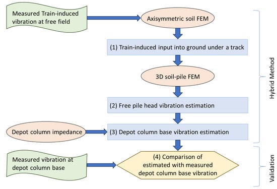
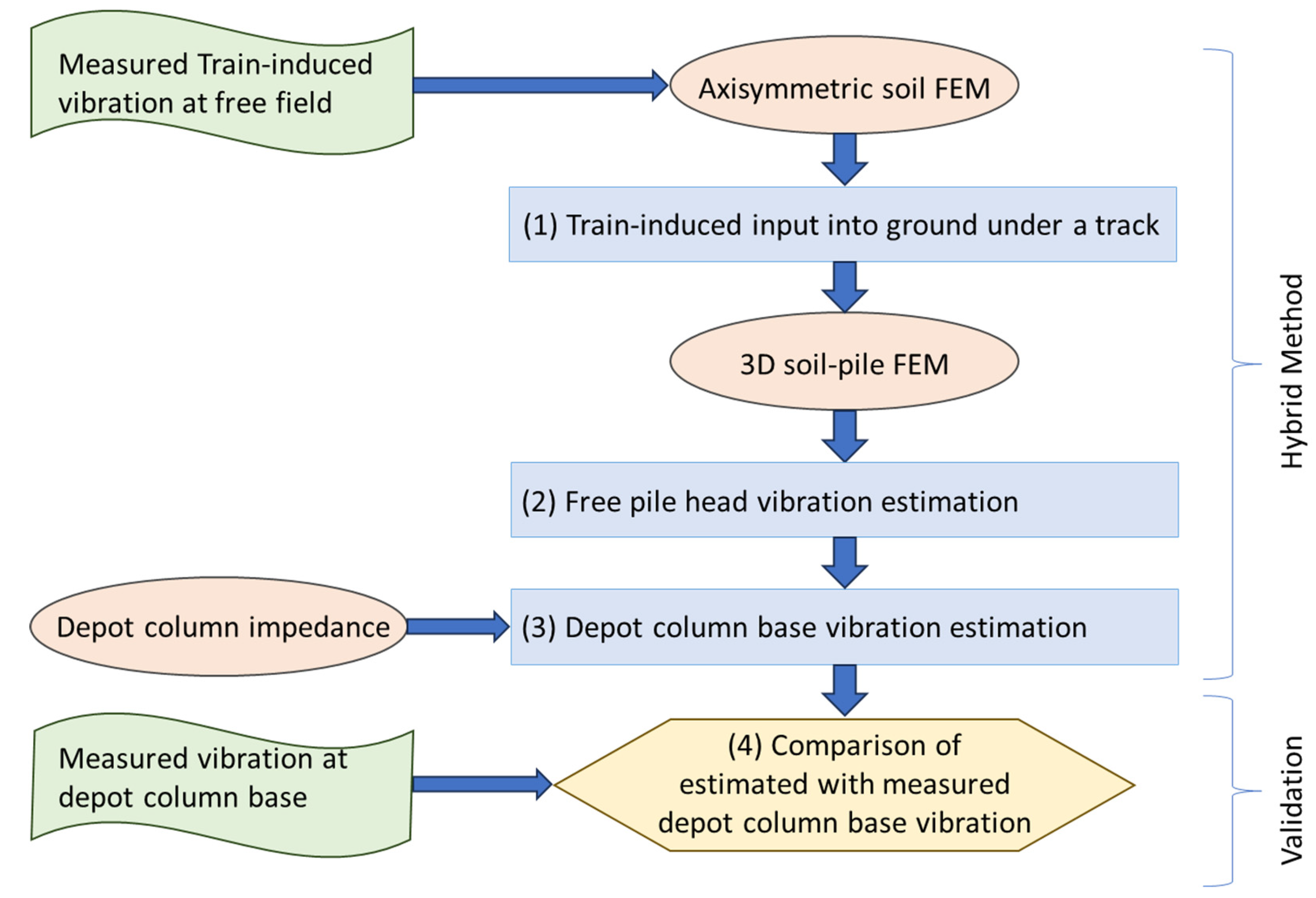
The present study focuses on vertical vibration induced by train operations, which is the dominant mode of transmission in metro depots. [16,17,18]. For train-induced vibration, it is generally accepted that vertical vibration dominates the transmission of vibration from the tracks through the ground via Rayleigh wave propagation in the soil, and subsequently into building structures, where vertical vibration transmission to upper floors is important. Building columns, due to their slenderness, inherently have much greater axial impedance than for bending or torsional vibration, which facilitates axial vibration transmission to upper floors [13]. Vibration measurements at free-field ground locations during train pass-bys on existing tracks are utilized to estimate ground vibration inputs that propagate through layered soils into depot foundation structures and over-track buildings. Finite element models estimate vibration transmission through layered soils to free-field ground locations and foundation structures. Finite element models estimate input impedances of depot foundations, which, along with impedance models of transmission into buildings, provide estimates of vibration levels in the buildings. The hybrid method, as shown in the flowchart in Figure 1, involves four steps:
Figure 1.
Proposed hybrid method for train-induced vibration prediction.
- Step 1.
- Train-induced Inputs into the Ground Beneath the Tracks
Axisymmetric FE models computed transfer functions of vibration transmission through soil layers from locations beneath the tracks to a free-field ground location at a suitable distance from the track and nearby depot or building structures. The transfer functions are the ratios of the measured ground-vibration amplitude to the input ground-vibration amplitude under the track, as a function of frequency. The amplitude of train-induced input vibration at the track is back-calculated by dividing the measured free-field ground amplitude by the transfer function.
The axisymmetric FE model, with input at the track and response at the free-field ground location, depends only on the distance between the locations and the frequency. The distance varies for different bogies on the train when positioned along the track where the free-field ground response is greatest. The transfer functions account for soil-layer properties and thicknesses obtained from borehole measurements. The field measurements and soil properties are described in Section 3. The axisymmetric FE model is described in Section 4, along with a discussion of how contributions to the free-field ground vibration from all bogies of a multi-car train are taken into account.
- Step 2.
- Free Pile Head Vibration Estimation
3D FE models are used to compute transfer functions for transmission from track inputs through soil layers to the head of a pile at a depot foundation column. The transfer function is the ratio of vibration at the pile head divided by the input ground vibration amplitude under a bogie at the track. The pile head motion, referred to as the free pile head vibration, is computed with no depot structure resting on it.
A 3-D model must be symmetric about a vertical plane passing through the track location and the pile. Again, the model depends on the distance from the bogie input at the track input location to the pile. The 3-D model is described in Section 5, alongside a discussion of how contributions to pile head vibration from all bogies on a multi-car train are taken into account.
Estimates of train-induced free pile head vibration levels, with no depot columns or depot structures in place, are generated using the transfer functions from the input ground vibration level at the track to a pile head based on the 3D FE model. The model includes the vibration interaction between the pile and soil layers at the depot column location. The free pile head vibration is the sum of energy contributions from all bogies. The free pile head vibration levels are presented in Section 5.
- Step 3.
- Depot column base vibration estimation
The coupling of the above-ground depot structures to the below-ground pile head is used to estimate pile head vibration during train pass-bys. It requires impedances at the pile head, looking into the ground, and looking up into the depot and building structure. The impedance of a pile was calculated using an axisymmetric FE model with input at the pile head and no train inputs. It accounts for vibration transmission into the pile and ground, as well as internal losses within both.
An impedance model of the depot and building structures describes the transmission of axial vibration from the pile head into the depot columns and the building. Vibration levels at the pile head, with the depot and building structures in place, were calculated based on the product of free pile head vibration levels times a factor containing the ratio of impedances of the depot structures and the pile. Subsequently, the train-induced vibration levels within the above-ground depot structure were derived by multiplying the vibration transmission ratios by the calculated pile head vibration levels, accounting for the depot structure. Pile head vibration predictions are described in Section 6.
- Step 4.
- Comparison of estimated and measured vibrations at depot column base
The validation of the proposed method is presented in Section 6.2, where estimated train-induced vibration levels at the bases of existing ground columns were compared with measured vibration levels obtained during train pass-bys. The validation data was not used in the back-calculation or in other steps in the method that generate vibration estimates at the ground column bases for comparison with the validation data.
3. Train-Induced Vibration Measurements
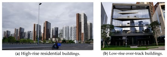
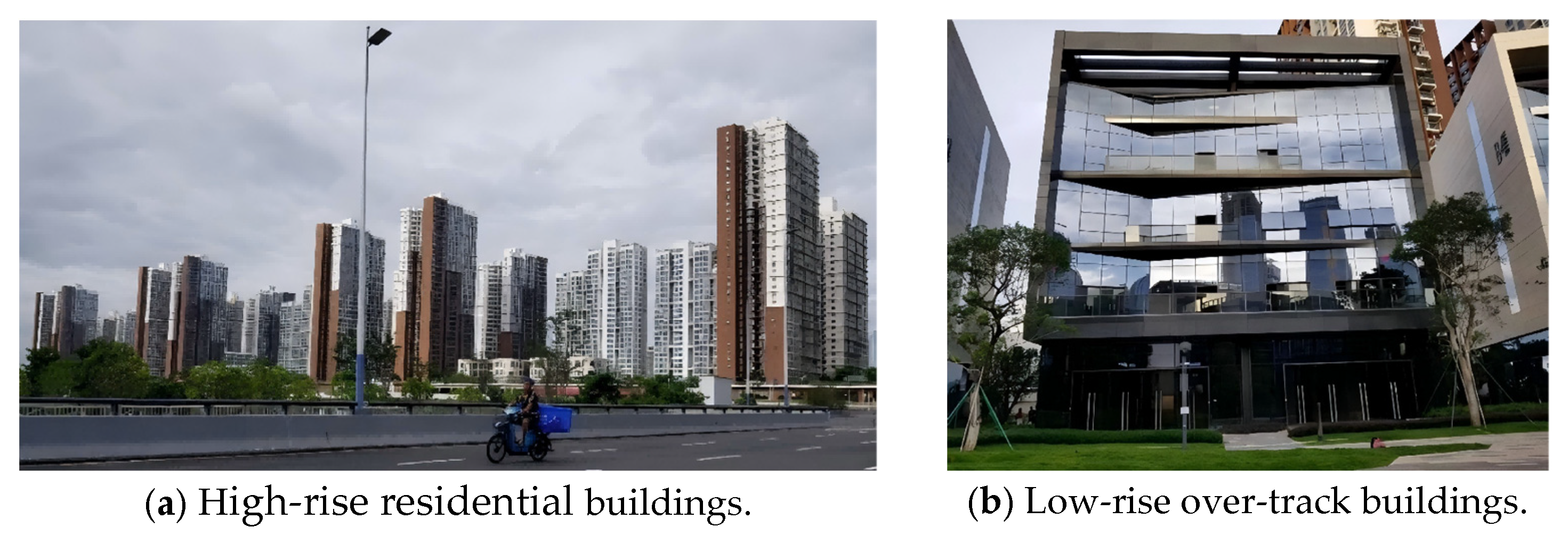
Figure 2 shows typical high- and low-rise over-track buildings above the Qianhai metro depot in Shenzhen, China, which occupies a total land area of about 489,700 m2. There are more than 25 high-rise residential buildings directly supported by pile foundations and over 30 low-rise offices supported above the tracks by depot columns and a transfer floor. The at-grade train tracks in the metro depot lie between depot columns (ground-level columns) that support the depot platform structures and over-track buildings.
Figure 2.
The Qianhai metro depot with over-track buildings in Shenzhen, China.
Train-induced vibration levels were measured at free ground locations for estimating train input vibration levels into the ground at the tracks and at the base of depot columns for validating model predictions. During the experimental study, data were recorded using a wireless data acquisition unit and a JM3873 acquisition system. The wireless unit was equipped with a built-in magnetoelectric accelerometer for vertical and horizontal measurements and supported an external third accelerometer. It featured 1 GB of storage capacity and 1 ms time synchronization accuracy. The sampling frequency was set at 1024 Hz, which, according to the Nyquist theorem, supports a maximum analyzable frequency of 512 Hz. Standard vibration measurement methods, equipment, and signal processing were employed, with further details shown in [19].
For the construction of new train depots, there are often no existing tracks at the proposed construction sites to make train-induced free-field vibration measurements. In this study, the depot tracks and structures were already in place and fully operational. As discussed in Section 4, train-induced ground vibration measurements at locations between depot columns were utilized to back-calculate train-induced vibration inputs at the tracks. Coulier et al. [20] found that the influence of nearby buildings on free ground vibration measurements could be ignored if the distances between the ground location and the building were larger than the Rayleigh wavelength in the ground. At the highest train-induced vibration frequencies, the Rayleigh wavelength was shorter than the distance to the nearest depot structures, making the measurements representative of free-field ground vibration.
3.1. Plan View of the Throat Area in the Depot
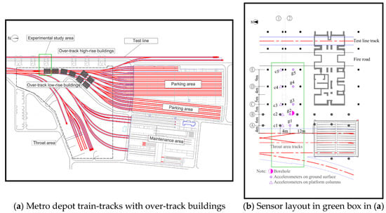
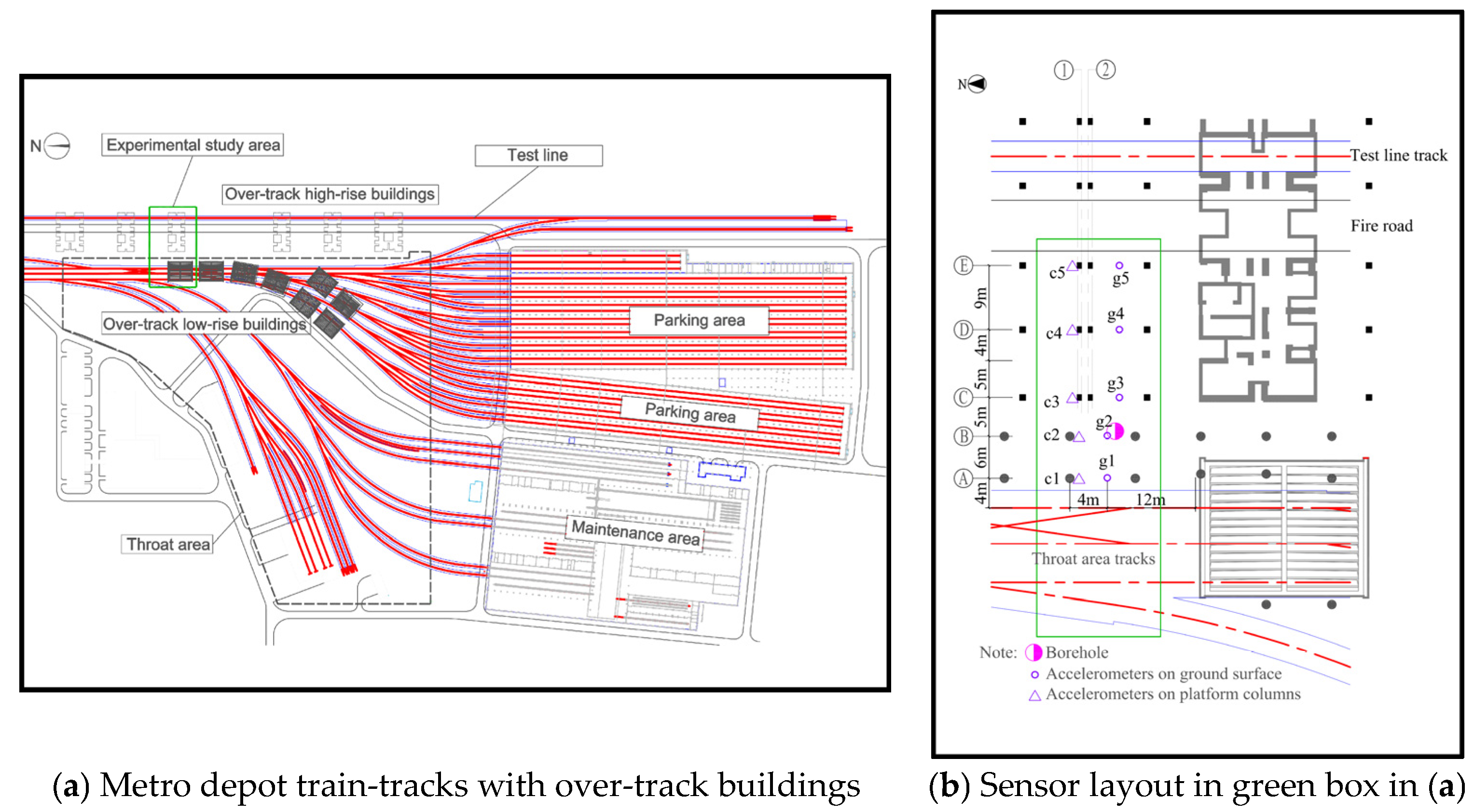
As shown in Figure 3a, a metro depot includes the throat area, a test line, and parking and maintenance areas. Tracks, with switches in the throat area, link the entrance/exit lines to those in the parking and maintenance areas. Train-induced vibration in buildings over the throat area was expected to be higher than in buildings over the parking and maintenance areas [19]. Figure 3b shows the accelerometer measurement locations, including those mounted on customized steel brackets on the ground and attached to platform columns.
Figure 3.
Plan view of the metro depot and measurement layout.
3.2. Soil Profile and Properties
Properties of the soil layers were determined from borehole measurements in between the tracks, free ground, and depot column locations. The geological structure used in the FEM was a layered half-space, based on the data in Table 1. This table presents the soil layer types, approximate thicknesses, Poisson ratios, densities, and their shear and compressional wave velocities.
Table 1.
Soil profile and properties.
3.3. Train Layouts
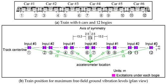
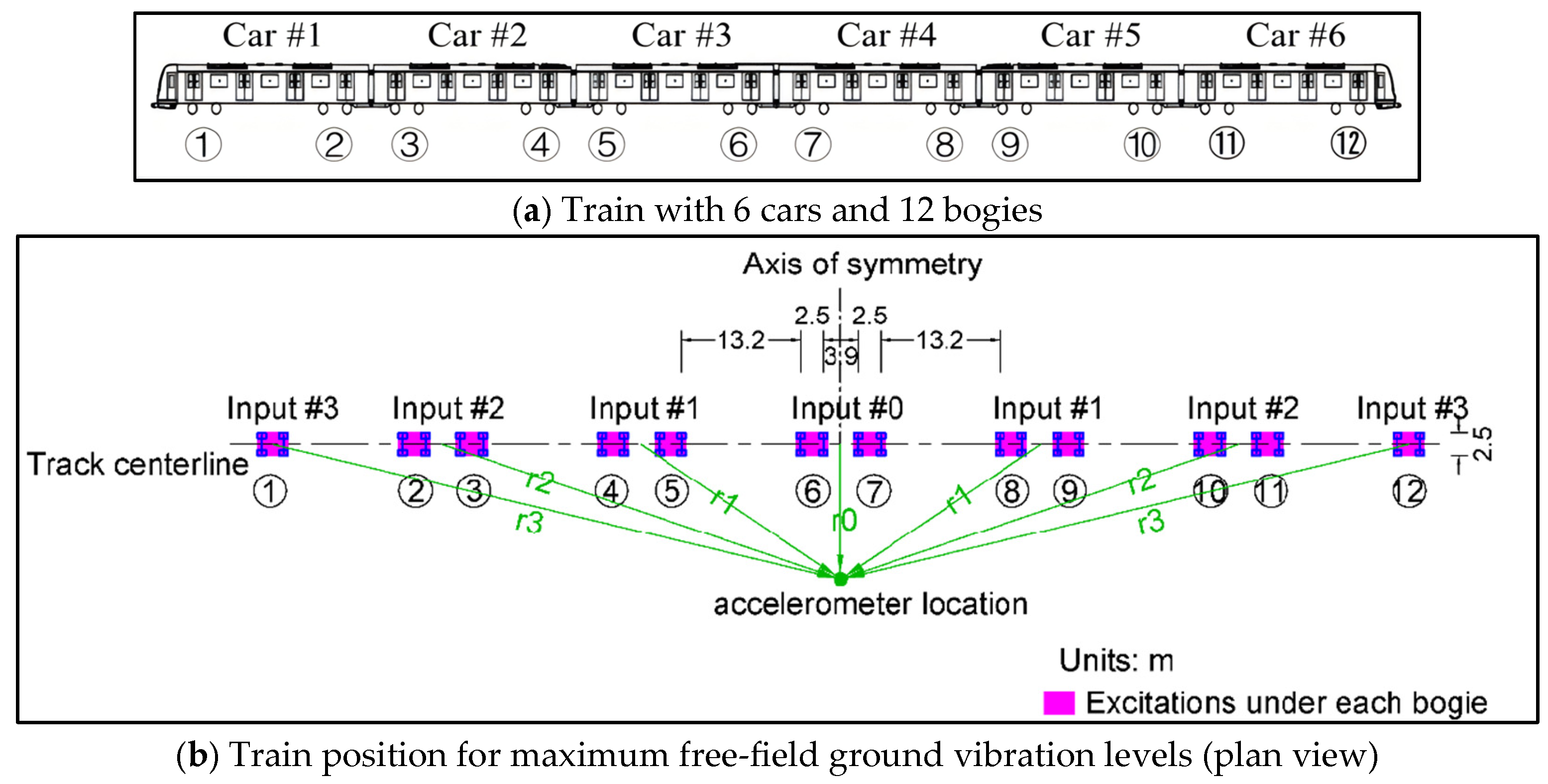
Figure 4 shows a schematic of ground surface inputs from a train with six cars. All cars and bogies were numbered as shown in Figure 4a, for a total of 6 cars with two axles each, 12 bogies, and 24 wheelsets. Wheel-rail contact forces are transmitted through the track tie and ballast structure, resulting in input ground-vibration levels under each bogie, which includes two wheelsets. It was assumed that inputs from individual bogies were statistically independent [21]. For railway vibration predictions, assuming that bogie inputs are statistically independent and exhibit comparable excitation levels is an accepted approach for straight, welded tracks without localized defects, such as unwelded joints or switches. Figure 4b shows the plan view of the train inputs at the point of closest approach with the greatest ground vibration levels during a pass-by. The distance between two wheelsets within the same bogie is 2.5 m. The distance between two bogies within a car is 15.7 m, while the distance between two bogies of two adjacent cars is 6.4 m.
Figure 4.
Ground inputs at the bogies of a 6-car train and ground measurement locations.
3.4. Vibration Spectral Analysis
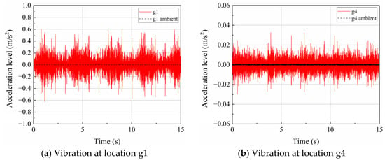
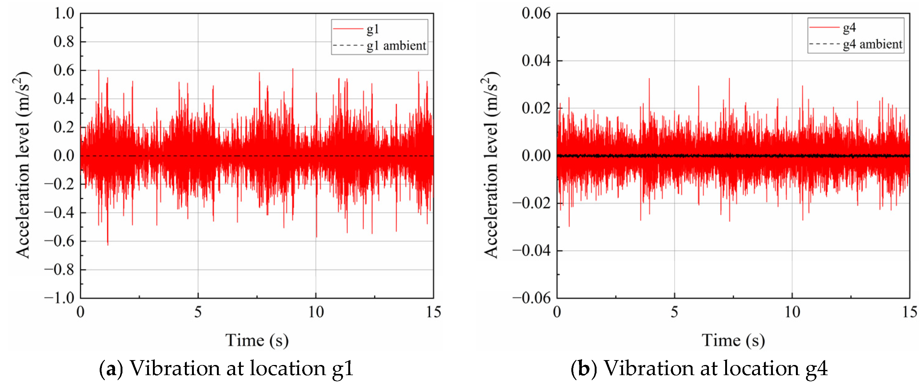
Ground vibration and ambient signals were measured at g1 through g5 during five pass-bys of the train on the nearest track. Figure 5 shows typical train-induced acceleration time histories at ground surfaces g1 and g4. Ground locations g1 through g5 were at 4, 10, 15, 24, and 33 m from the tracks, respectively. If either the ground measurement or the column location is close to the tracks in the near-field of ground vibration, it can potentially result in significant differences between estimates of column vibration and actual measurements. As a result, vibration measurements at g1 and g2 were not used. Only measurement locations g3, g4, and g5 were used to estimate column vibration levels at c3, c4, and c5. The distances from the track to the ground measurement and the column locations were reasonably large, likely beyond the near-field.
Figure 5.
Measured free-field ground vibration during a train pass-by.
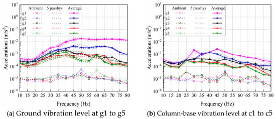
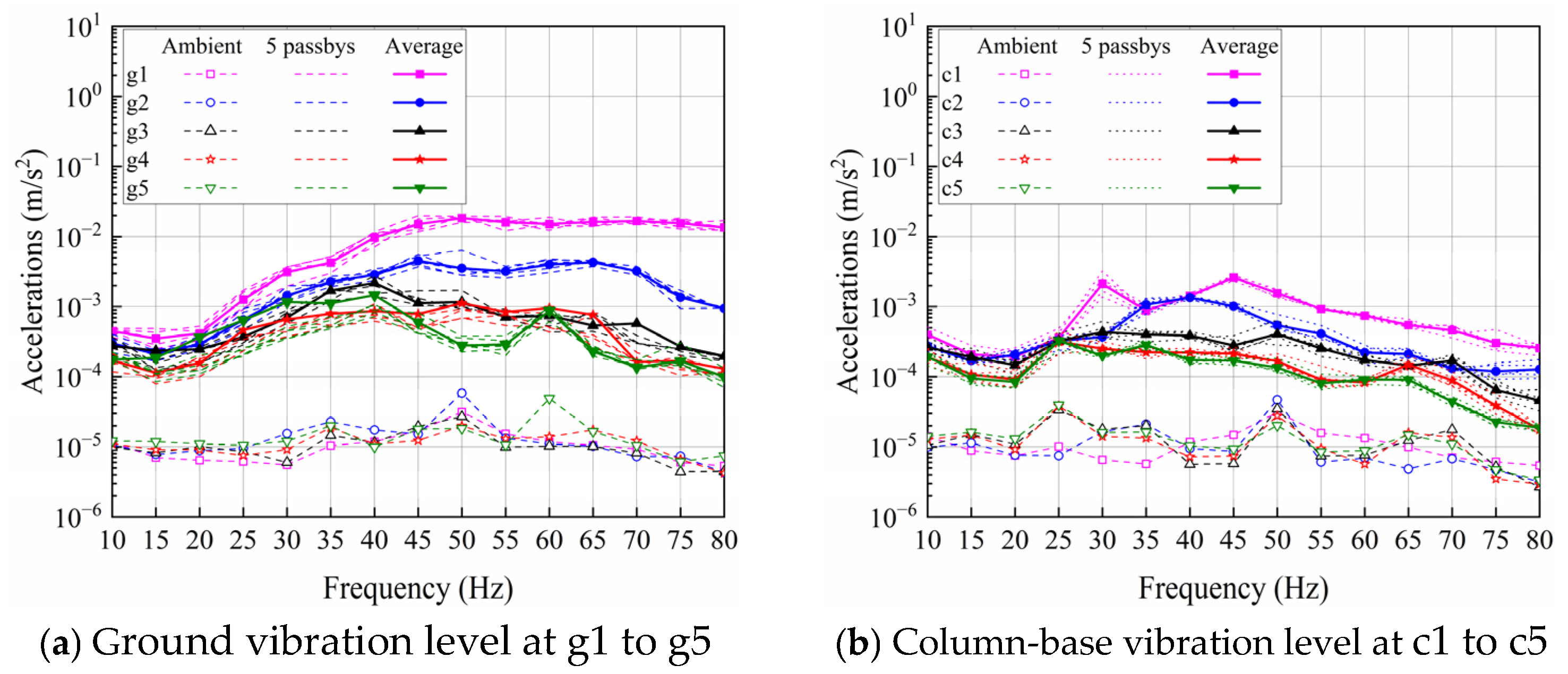
Figure 6 show train-induced and ambient vibration spectra along the ground surface from g1 to g5 and along the base of depot columns from c1 to c5, respectively. The measured train-induced vibration levels were significantly greater than ambient levels. Frequency ranges up to 80 Hz are shown in these figures, consistent with the FTA guideline [8].
Figure 6.
Measured train-induced acceleration levels (RMS).
For the measurements at the ground and column base locations, acceleration levels decreased with increasing distance from the track. Figure 6a shows that measured train-induced vibration levels for multiple pass-bys were closely spaced and repeatable. Ground vibration levels increased up to 40 Hz and then decreased. Figure 6b shows similar trends except that column vibration levels were significantly less than ground levels above 40 Hz, especially for columns c1 and c2, which are closer to the track than other columns.
4. Back-Calculation of Train-Induced Ground Vibration Input at Tracks
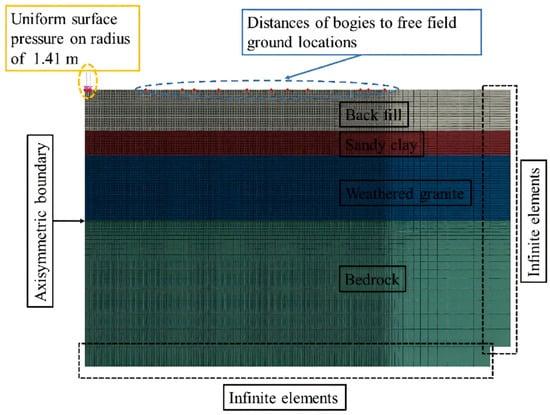
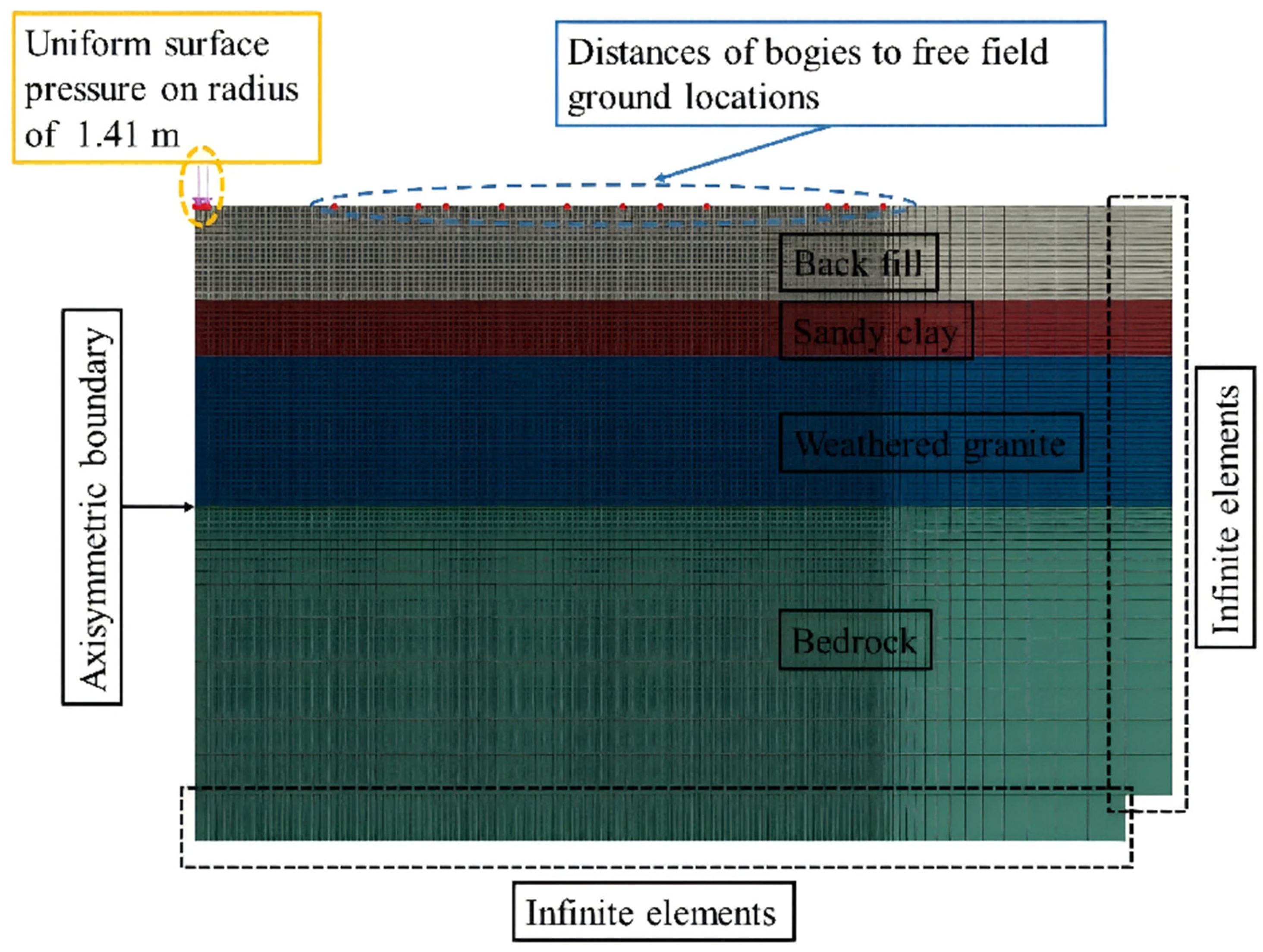
The FEM shown in Figure 7 was used to calculate transfer functions from bogie-induced ground input vibration to ground locations at various distances as shown in Figure 4. The axisymmetric model accounts for different properties of the soil layers, as given in Table 1. The bogie, centered at the model’s origin, and ground locations at various distances are shown on the ground surface. ABAQUS version 2017 software was used to develop all FE models in this study. A 1% damping ratio [22] was used for saturated soil layers at the depot site, including parts of the top layer, due to its high water table.
Figure 7.
Axisymmetric FEM of vibration transmission from bogies to ground locations.
To preserve axisymmetric conditions, rollers against horizontal motion were applied at all nodes on the left side of the axisymmetric boundary. The ground input under a bogie was modeled as uniform pressure acting over a circular region of radius 1.41 m at the surface. The actual vibration input into the ground comes from two wheelsets on the track’s two rails. At frequencies of interest, differences in the ground vibration induced by four spatially separate wheels in a bogie, in comparison with a uniform input induced by a disc, would be limited to the ground near the bogie. Input to the FE model represents the average total force departed into the ground from the four wheels, whose extent was comparable to, and slightly larger than, that of the bogie. The physical basis for this simplification lies in the load transfer mechanism within the track structure. The bogie vibration is transmitted through the wheels to the rail as discrete point loads. However, the rail, sleepers, and ballast collectively redistribute these point loads into a more continuously distributed pressure acting on the rail subgrade. Therefore, representing the bogie input as a distributed pressure load over an area comparable to the bogie dimensions is a reasonable approximation [18,23] that captures the overall load distribution while enabling an efficient axisymmetric finite element formulation. Infinite elements [24] were used at the outer radius and on the bottom surface of the model to absorb waves radiating from the input and minimize reflections at the boundaries.
Table 2 lists the distances between the ground measurement locations and the different bogies on the train when the train is centrally positioned relative to the ground locations. As shown in Figure 4b, when the middle of the train was in line with the ground locations, the distances from bogies symmetrically positioned on either side of the middle of the train to the ground locations were equal. They were also at minimum distances from the ground location to maximize transfer function values consistent with the maximum ground vibration levels during the train pass-bys.
Table 2.
Distances from ground measurement locations to each bogie (m).
The FEM is 105 m in the radial direction and extends 68 m deep into the soil layers to bedrock. According to Table 2, the farthest ground location g5 was 33 m away from bogies 6 and 7 (b0) and 74 m away from bogies 1 and 12 (b3). According to Table 1, the shortest shear wavelength at 10 Hz was 18.6 m in the top fill layer. The transfer function for bogies 1 and 12 to ground location g5 was at a distance of 31 m away from the outer radial boundary of the model, which was around 1.7 times the shear wavelength in the top layer at 10 Hz and greater at higher frequencies. The FE model size used was sufficient to avoid adverse effects of reflections at its outer radial boundary [25]. According to Table 1, the shortest wavelength in the top layer at 80 Hz was 2.3 m. To capture the highest-frequency wavelength of interest (80 Hz), fundamental finite-element wave-propagation principles require at least 1/6 to 1/2 of a wavelength per element [25]. Thus, the smallest element size of 0.2 m in the region of primary interest strictly satisfies these established convergence requirements, ensuring that no significant calculation errors occur in the vibration transfer functions. The model consisted of 31,622 elements.
4.1. Transfer Functions from Bogie Inputs to Ground Locations
In this research, we have used acceleration measurements at g3, g4, and g5. The transfer function to motion of the ground due to input from one bogie is defined in the frequency domain as
The index i = 3, 4, 5 identifies the ground location, and j = 0, 1, 2, 3 identify the bogie location, as shown in Figure 4b. The numerator is the vibration level at ground location “gi”, and the denominator is the ground vibration input from bogie “bj”. The transfer function is a function of “rij”, i.e., the distance between the ground location “gi” and the bogie location “bj”.
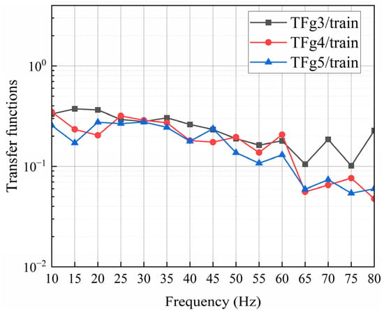
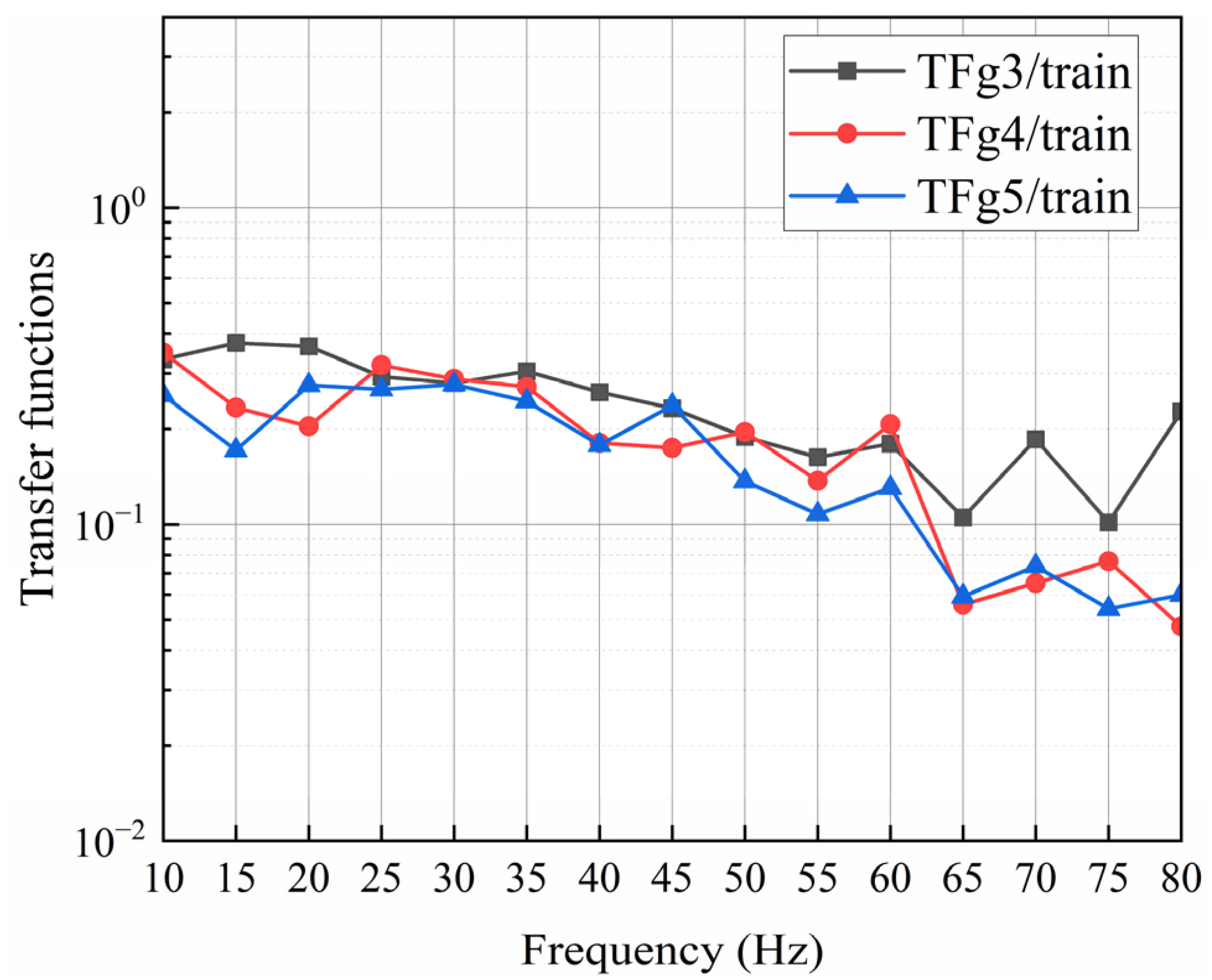
The transfer function as defined in Equation (1) accounts for vibration input from only one bogie to one ground location, while the transfer function in Equation (2) below sums contributions to the ground location from all bogies on the train, assuming they are statistically independent with the same input level, , and is referred to as the train transfer function () to a ground location.
Figure 8 compares train transfer functions to ground locations g3 to g5 based on Equation (2), using individual bogie transfer functions obtained from the axisymmetric FEM, as shown in Figure 7.
Figure 8.
FEM predicted train transfer functions to ground locations from all bogies.
4.2. Back-Calculation of Ground Vibration Input Due to a Bogie
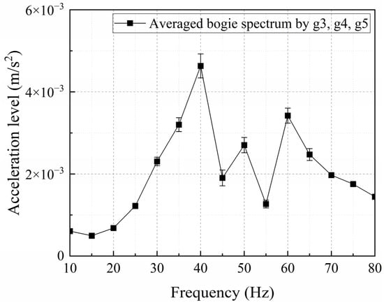
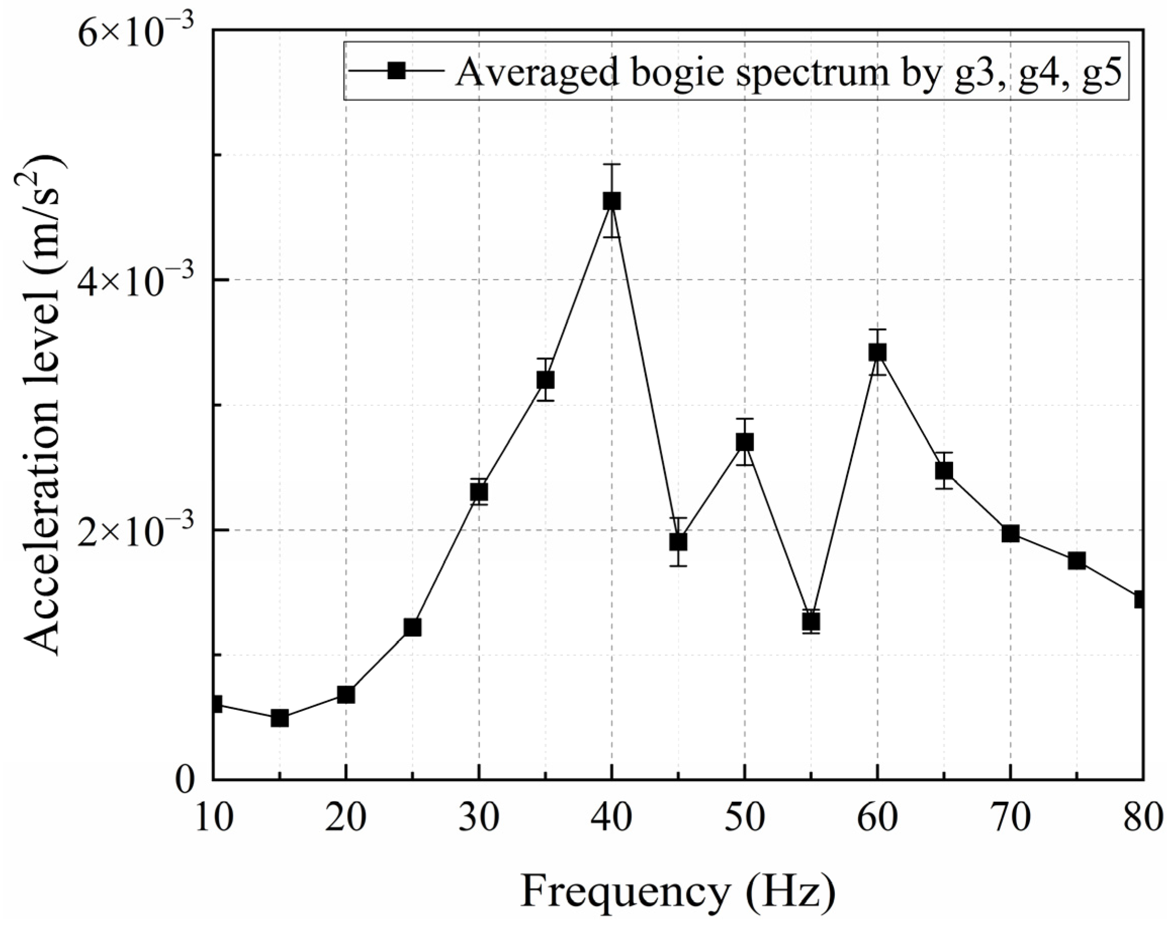
Acceleration spectra on the ground at a bogie Abogie were back-calculated based on each vibration spectrum at ground locations g3, g4, and g5, shown in Figure 6a, using Agi in Equation (2). Train speeds during testing were confined to relatively low speeds of 5–15 km/h. All trains were of the same type with identical marshaling configurations. Individual calculations of bogie vibration inputs based on measured ground vibration levels at locations g3, g4, and g5 were averaged to obtain the bogie’s ground input vibration level, as shown in Figure 9. Averaging was done to account for possible inhomogeneities in soil properties.
Figure 9.
Average of back-calculated ground vibration spectral input at a bogie.
Based on Equation (2), the average back-calculated bogie input vibration level is expressed as
Following the first-order Taylor expansion-based error propagation formula, the variance of is given by
Assuming that the measured surface vibration levels to are independent, the uncertainty in becomes
Conversely, assuming perfect positive correlation among to yields the upper bound of the uncertainty:
The standard deviations are derived from the measurements, as illustrated in Figure 6a. This upper-bound case is presented as the vertical error bars in Figure 9. The variability among the measurements at points g3 to g5 is relatively small, resulting in a correspondingly limited variation in the predicted values for . In practice, when additional uncertainties from the transfer functions are considered, such as those arising from their source using finite element modeling, the overall variability in is expected to be larger than the estimate that assumes no uncertainty in the transfer functions.
5. Prediction of Free Vibration Levels at a Pile Head
This section presents predictions of train-induced vertical vibration levels at the free pile head, with no depot or building structures supported by the pile. An axisymmetric FE model cannot be used in this section due to the presence of the pile at a distance from a bogie. Transfer functions of pile head vibration divided by the bogie input vibration still depend on the distance from a bogie to the pile.
The pile affects the vertical motion of the ground, where axial vibration of the pile is induced primarily by vertical shear stresses along the interface between the ground and pile as a function of depth, assuming no slippage due to the low soil stiffness compared to the large axial stiffness of the pile. Bending vibration within the pile is also induced by interface stresses involving horizontal shear and normal stresses perpendicular to the pile surface.
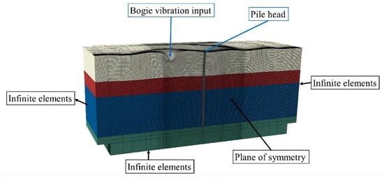
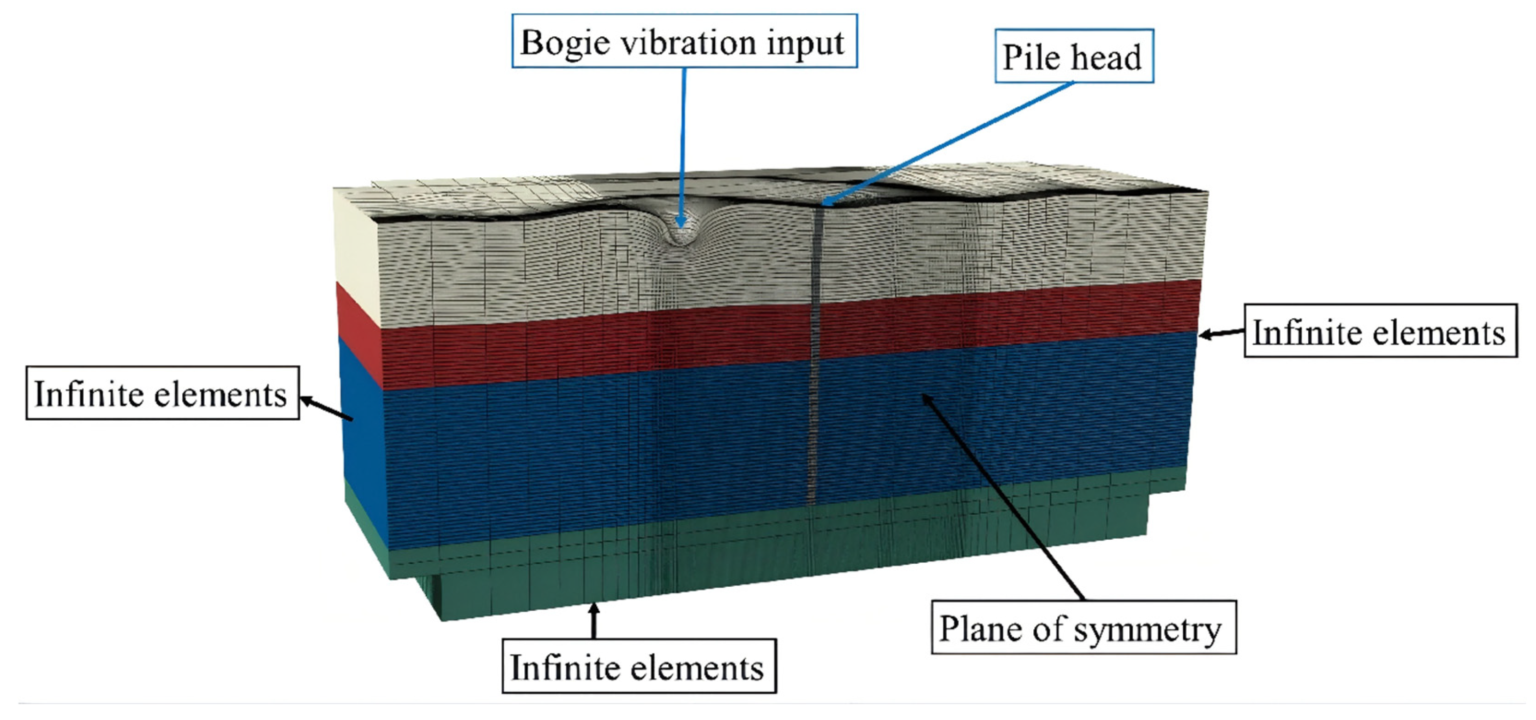
The FE model that estimates the transfer functions from bogie to vertical motion at the pile head uses symmetry about a vertical plane that contains both the bogie and the pile head. The symmetry boundary condition was applied by constraining the displacement component normal to the symmetry plane, while the in-plane displacement components were allowed. The use of the symmetry plane reduces the extent of the model because only one side of the plane is modeled. Figure 10 shows the symmetric 3D FE model for pile location c3, with input applied to bogies #6 and 7 (Figure 4b), which are 15 m apart. The same distances in Table 2 apply to both the pile and ground models, as the train was positioned at the minimum-distance location along the track, resulting in maximum vibration level at the pile head during a pass-by.
Figure 10.
3D FE model for predicting transfer functions for input at a bogie to vertical motion at a free pile head.
The ground input at a bogie, shown in Figure 10, was a uniform pressure on a 1.41 m radius disc. The signal was a sine wave at frequencies of interest from 10 to 80 Hz in 5 Hz increments, as shown in the figures. The plot also shows vertical variation along the pile and in the ground. The surface motion was greatest near the bogie input. The motion decreased significantly with distance from the bogie and with depth into the soil layers. The model was 134 m long along the track, 32 m wide perpendicular to the track, and vertically 40 m long extending into the bedrock. The smallest element size was also 0.2 m to capture ground-borne vibration up to 80 Hz, with a total of 386,854 elements.
A 2% damping ratio was used for the concrete pile. The response of a pile embedded in the ground is much lower than the response level associated with seismic loading. It remained well below the range corresponding to 50% of the concrete capacity. Therefore, the use of a 2% damping ratio for the concrete pile is considered reasonable, in accordance with the value suggested for prestressed concrete structures in Ref. [22].
The bedrock supports the bottom of the concrete pile. The radius and length of the pile are 0.5 m and 32 m, respectively. The mass density of the concrete pile is 2400 kg/m3, Young’s modulus is 30 GPa, and Poisson’s ratio is 0.2. Soil properties are listed in Table 1.
The transfer function of free pile head motion from a ground input at a single bogie is defined in the frequency domain as
Equation (7) is similar to Equation (1). At the same time, the numerator is the averaged acceleration at the free pile head location i with subscript “phi”, and the denominator is the averaged ground acceleration input under bogie “bj”. Similar to Equation (2), the transfer function of free pile head vibration due to the train excitation from all 12 bogies was defined based on an energy summation as
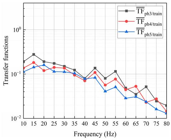
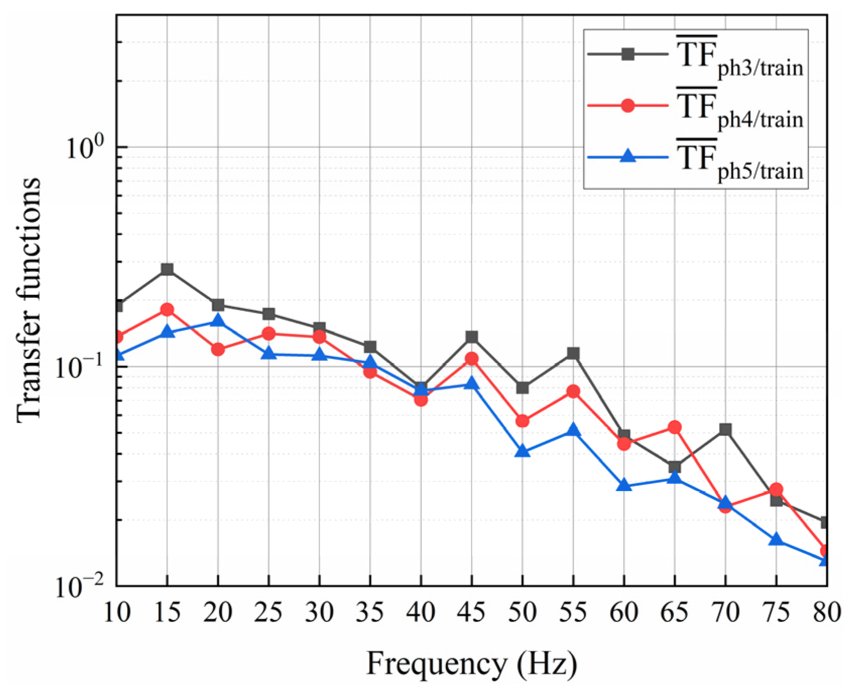
As indicated in Equation (8), the acceleration level at the pile head for a train pass-by can be predicted with and , where is the average ground vibration input under a bogie from Section 4. Figure 11 shows plots of transfer functions to . Subscripts “ph3”, “ph4”, and “ph5” represent the bogie-to-pile distances of 15 m, 24 m, and 33 m, respectively.
Figure 11.
FEM predicted train transfer functions to the pile head.
FEM predicted train transfer functions to the pile head, including contributions from all bogies, decreased more rapidly at higher frequencies than for transfer functions to the ground surface, as shown in Figure 8. The faster attenuation of the pile head vibration transfer function at high frequencies is due to the coupling between the soil and pile. When high-frequency (short-wavelength) stress waves in the soil propagate into an axially stiff (longer wavelength) concrete pile, a severe impedance mismatch occurs at the soil-pile interface. This results in significant scattering and reflection of the incident ground wave, thereby reducing transmission of the ground wave into the pile.
The frequency-dependent transmission behavior is influenced by the types of waves present in the soil. Body waves (P-waves and S-waves) and surface waves (Rayleigh waves) dominate the free-field ground vibration at different depths and distances from the source. When incident waves encounter the pile, the conversion and scattering phenomena depend on the wavelength relative to the pile diameter. At high frequencies, the ground propagation wavelengths become comparable to or smaller than the pile diameter, where complex wave scattering further reduces the energy transmitted into the pile [26].
The total vibrational energy at the pile head contributed by bogie locations 6 and 7, 4 and 5, and 8 and 9 on both sides accounted for 93.8% of the total vibrational response due to the six-car train, evaluated at the lowest frequency of interest in this study, i.e., 10 Hz. At higher frequencies, the contribution from the middle bogies would be even greater, as the shorter propagation distances further diminish the relative contributions from the end bogies. It indicates that the response from bogie inputs farther along the train could have been omitted with negligible loss of accuracy. This simplification was adopted as a balance strategy between computational cost and prediction accuracy, reducing the computational effort of the finite element model without substantially compromising prediction accuracy.
6. Coupling to Depot Column at Pile Head
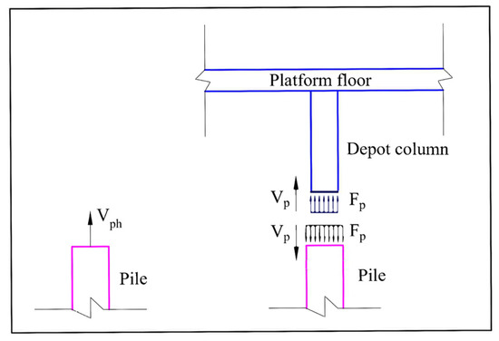
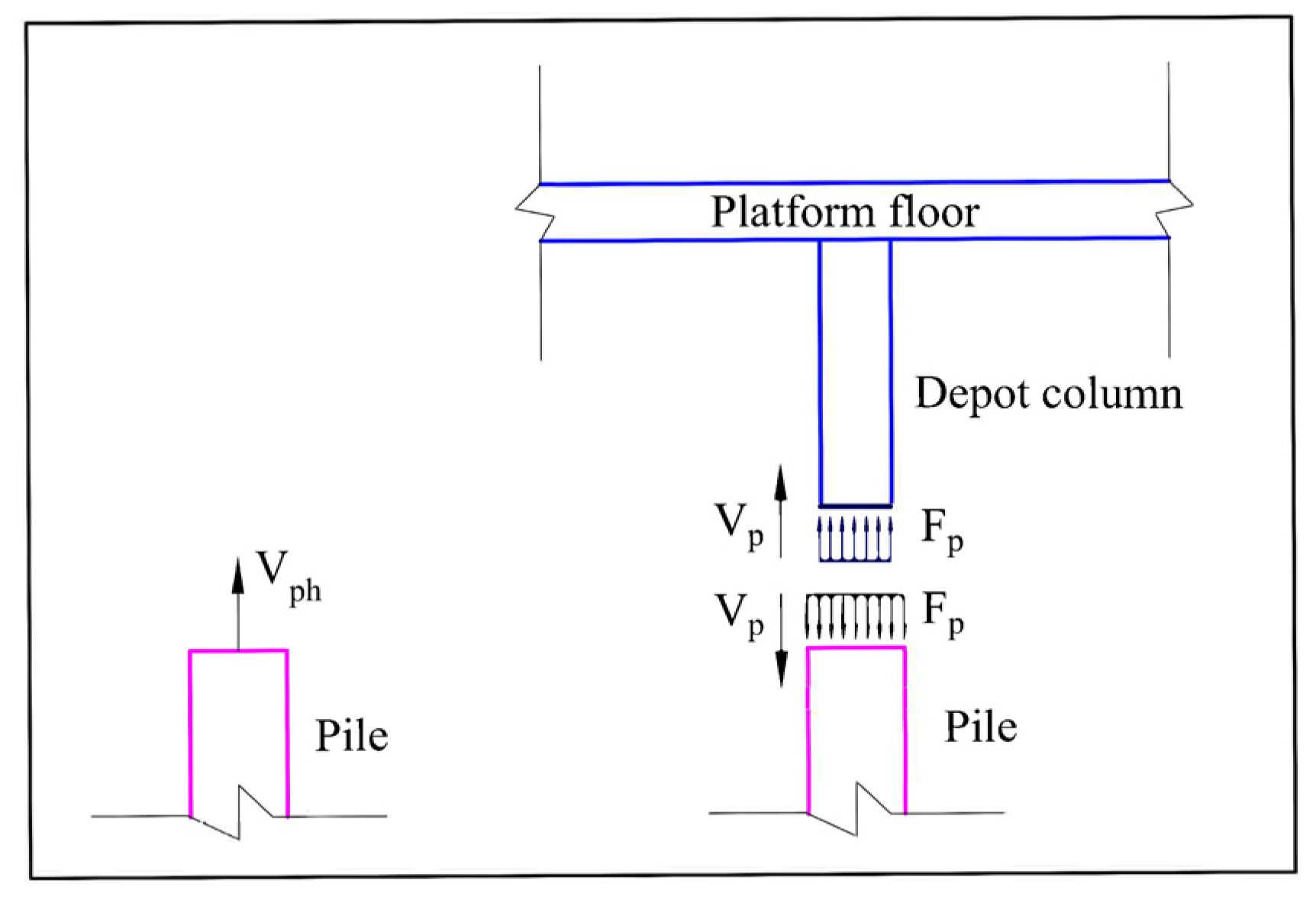
The prediction of train-induced vibration levels within over-track buildings above metro depots is based on vibration inputs at the pile heads with the depot structures in place. The free motion of a pile head will potentially be reduced by the impedance of the depot structures supported by the pile. Figure 12 illustrates the prediction of pile head motion with the depot structures in place, , based on the free pile motion, .
Figure 12.
Prediction of pile head velocity without and with depot structure.
The amplitudes of vibration velocity and force at the train inputs, subscript t, and the pile head, subscript p, are related by the system impedance matrix, [Z]:
Equation (9) is used for cases with no depot column to obtain the free pile head velocity Vph with Fp = 0. Vp is the pile head velocity for the case with a nonzero force Fp at the pile with the depot column in place. The ratio is equal to the ratio of the corresponding accelerations , as presented in Equation (10):
In Equation (10), is the impedance of the depot structures at the pile head, and is the finite element evaluation of the impedance of the pile in the soil. is the free pile head acceleration level due to train inputs without the depot structures, given in Section 5, and is the acceleration level at the pile head with the depot structures in place. This study focuses on vertical train-induced vibrations, which are dominant in metro depot environments. Accordingly, Equation (6) considers only axial impedance coupling at the pile-column joint, as vertical vibration energy primarily transmits through axial waves. Bending and torsional impedances are excluded because the excitation is predominantly vertical under low-speed, straight-track conditions, and axial impedance of the columns is significantly larger than bending impedance, rendering any bending or torsional contributions negligible [15,16]. While this simplification is appropriate for the present case, it is acknowledged that bending and torsional effects may become relevant under horizontal excitation or flexible connection scenarios.
6.1. Predictions of Pile Head Impedance and Train-Induced Depot Column Vibration Levels
An axisymmetric FE model was used to calculate the impedance at the head of a pile buried in soil. The above-ground superstructure considered includes a large-diameter concrete depot column that supports the depot platform floor (and potentially over-track buildings, if present at other locations), as shown in Figure 12. The depot column has a Young’s modulus of 32.5 GPa, a density of 2400 kg/m3, and a radius of 0.6 m. The platform floor has a Young’s modulus of 31.5 GPa and a density of 2390 kg/m3. The platform floor has a mass-equivalent thickness of 0.788 m and a stiffness-equivalent thickness of 1.381 m [14]. Both the depot column and platform floor have damping loss factors of 4% [27].
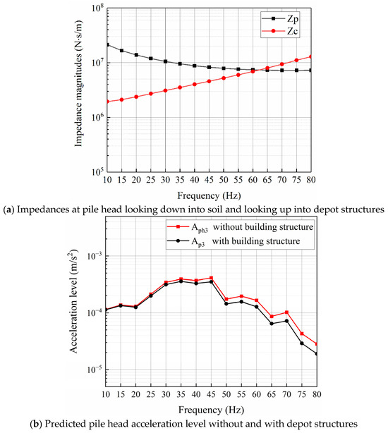
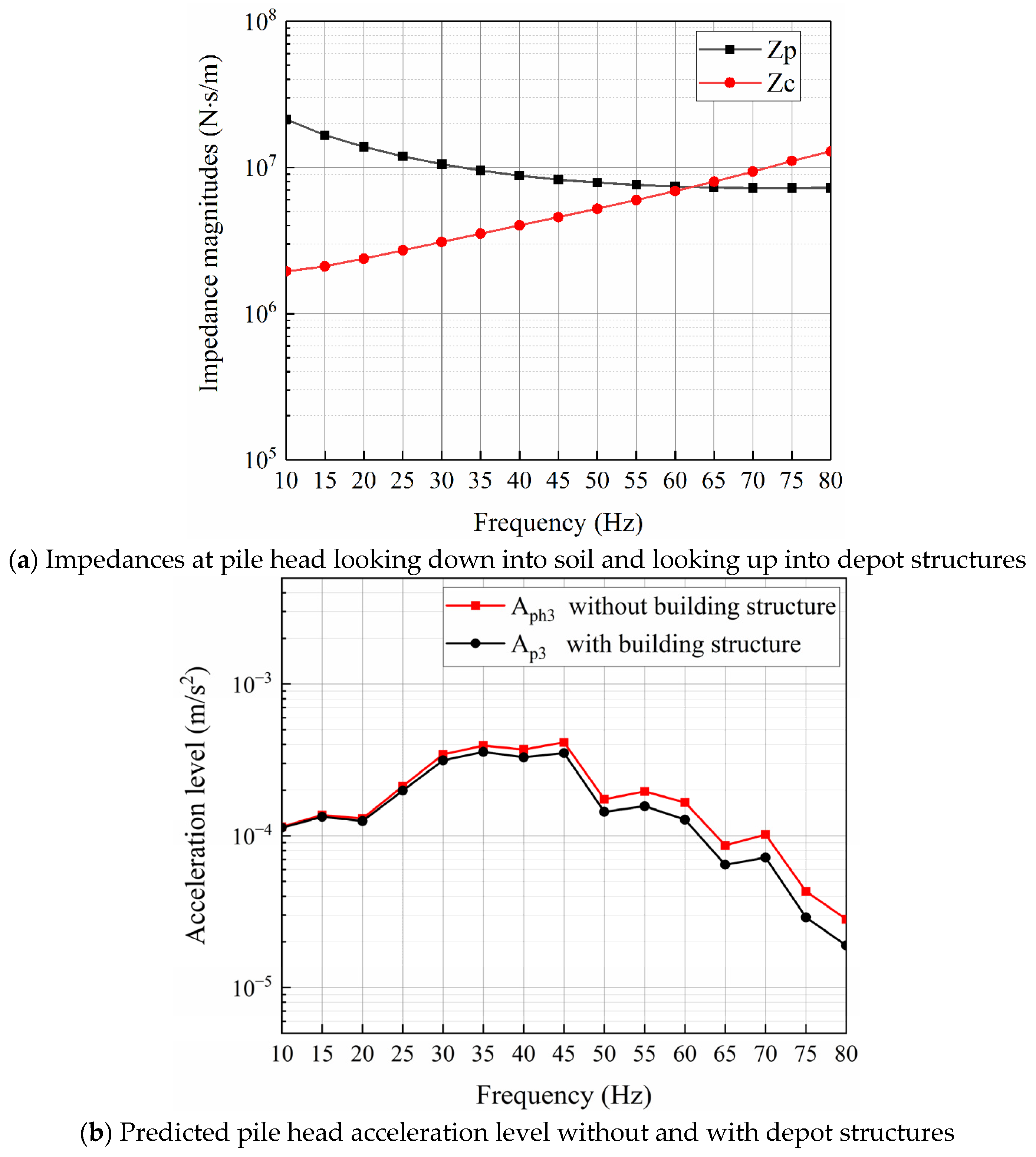
Figure 13a compares the FEM calculation of the impedance of the pile head and the impedance model calculation of the impedance of the depot structure, including only a depot column and a platform floor at location c3. There was no over-track building above the platform floor at location c3.
Figure 13.
Influence of depot structures on pile head acceleration level.
Figure 13a shows that the free pile head impedance was significantly larger than the depot structure impedance at lower frequencies up to 50 Hz. At the same time, the impedances were comparable in the range of 50~80 Hz. Equation (10) implies that the building structures did not greatly affect the pile motion below 50 Hz, but possibly affected the free pile head motion and transmission into the building in the frequency range above 50 Hz. Figure 13b compares predicted vibration levels of the pile head without and with the depot structures in place at location c3. The depot structures resulted in a negligible reduction in free pile head vibration at low frequencies and a limited reduction at higher frequencies, with an approximate 4 dB reduction at 80 Hz.
The impedance of the depot structure was much smaller than the pile impedance below 40~50 Hz, i.e., in Figure 13a. In that range, the denominator of Equation (10) was close to 1, and the pile head motion without or with the building structure in place did not differ greatly. When the impedances were comparable (above 40~50 Hz), and the depot column lightly loaded the pile head, the vibration levels were slightly reduced.
6.2. Validation of Predicted Vibration with Measurements at Column Base
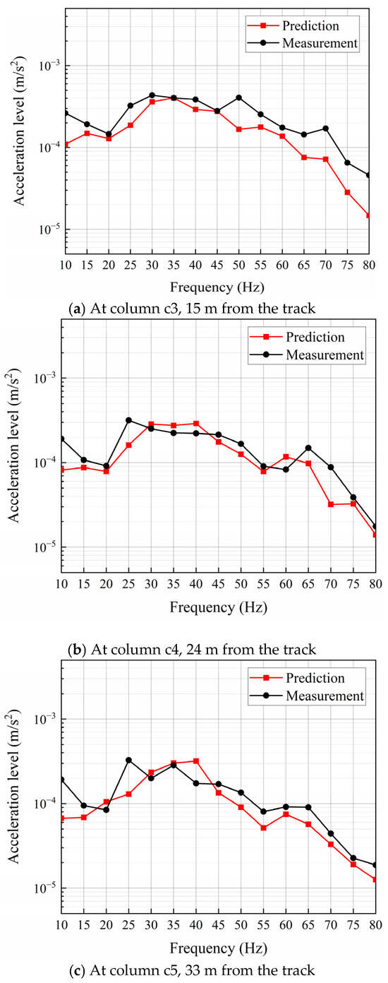
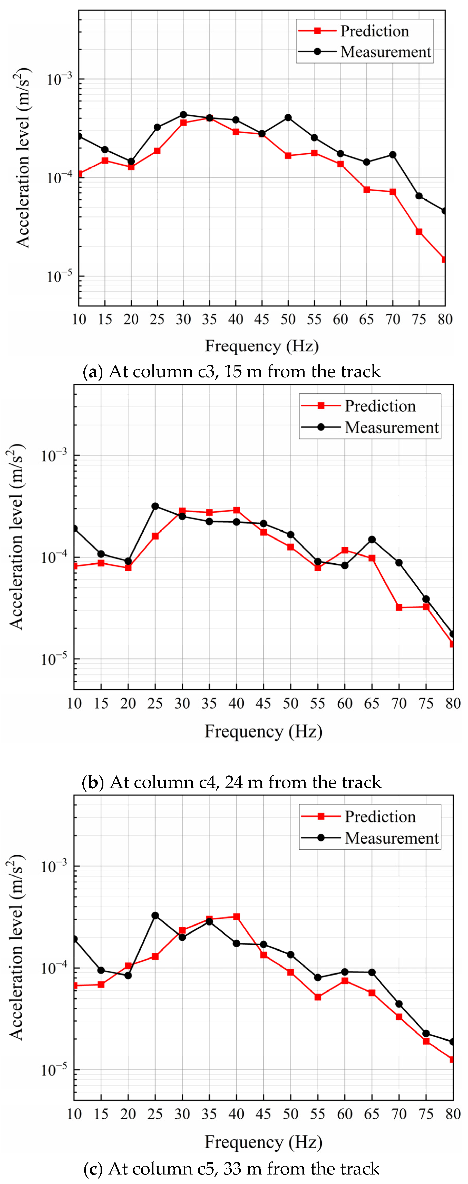
The transmission from the pile head to the depot platform slab and building floors was systematically investigated in our previous work [16,28]. Given the complexity of the upstream train-soil-pile-depot column coupling, the present study focuses specifically on this phase. By mathematically linking the proposed method to our previously established depot column-to-superstructure models, the full train-soil-pile-structure vibration transmission pathway is effectively validated. In addition, since the prediction model is formulated in the frequency domain using transfer functions and impedance concepts, validation is appropriately based on frequency-domain characteristics, i.e., the acceleration spectra. Time-domain quantities such as peak values and vibration duration cannot be directly predicted within this framework without additional assumptions, such as phase reconstruction. Predictions of train-induced vibration levels at the bases of depot columns at locations c3, c4, and c5 were compared with measurements, as shown in Figure 14a–c.
Figure 14.
Comparison of predicted with measured pile head acceleration levels.
The comparison of estimated and measured acceleration levels at the pile head supporting the ground column is shown in Figure 9. Differences between model vibration predictions and field measurements were frequency-dependent and location-dependent, as expected. At higher frequencies, the vibration response is generally more sensitive to local modeling assumptions and measurement noise. Therefore, the observed deviations are likely attributable to a combination of factors, including simplifications in the soil stratification, sensor accuracy and measurement uncertainty, assumed damping ratios in the model, the treatment of soil-pile interaction, and variability in train operating conditions during the measurements. In addition, as shown in Figure 6b, measurements at depot columns c3 to c5 exhibited the maximum signal-to-noise ratio in the frequency range of 30 to 45 Hz, which is also the frequency range with the highest train-induced vibration energy in the far-field, as illustrated in Figure 6a. Correspondingly, prediction accuracy was highest in this frequency range. Since the average field measurements were used to back-calculate train excitation inputs to the subgrade, the discrepancies between predictions and measurements across different depot columns also vary. The maximum absolute errors in the target frequency range at c3, c4, and c5 were 9.3 × 10⁻⁵, 6.8 × 10⁻⁵, and 1.5 × 10⁻⁴, respectively, corresponding to 2.4 dB, 2.3 dB, and 5.3 dB, all occurring at 40 Hz.
7. Discussion
The main novelty of the proposed method is predicting train-induced vibration transmission into over-track buildings using free-field measurements, thereby eliminating the need for direct instrumentation at depot columns, a significant practical solution in operational metro depots.
There are other novelties of the proposed method compared with previous studies. Unlike empirical approaches such as the FTA guideline [8], which employs frequency-independent coupling factors, the proposed method accounts for frequency-dependent soil-pile-structure interactions through detailed finite element and impedance modeling. In contrast to fully analytical models that require extensive parameterization of wheel-rail dynamics and track irregularities [5,12], the proposed method leverages free-field measurements to back-calculate “equivalent” track inputs into the ground, reducing reliance on uncertain input parameters. At the far-field distances evaluated for the field measurements, the input into the ground has a minimal effect on the ratio of FE transfer functions to the free-field and pile locations. It is simply an “equivalent” input for both the simultaneous free-field ground measurement and the ground column measurement above the pile-head. Assuming bogie inputs are equal, they cancel in the ratio of the FE transfer functions, leading to a highly efficient method.
The impedance-based coupling employed in Step 3 builds on prior work by Sanayei et al. [13] and Zou et al. [14,15], which demonstrated the effectiveness of axial impedance models for predicting vibration transmission into a building through columns. The present study extends these concepts to the more complex interactions between train, soil, pile, and depot structures, which have not been systematically addressed in previous hybrid frameworks.
The proposed hybrid method has several key strengths and innovations. First, its modular structure allows individual components (e.g., soil modeling, pile impedance, building impedance) to be refined independently without requiring revalidation of the entire framework. Second, using free-field measurements to back-calculate bogie inputs eliminates the need for trackside instrumentation, which is often not feasible in active depots due to security and operational constraints. Third, the framework’s linear scalability enables applications for different train configurations and speeds. The hybrid method, assuming statistically independent and equal bogie inputs acting on the ground, simplifies the development of the FE models of vibration transmission through the soil.
Unlike earthquake-induced vibrations, train-induced vibrations are classified as “micro-vibrations”, typically well within the linear elastic range. Therefore, using a bonded, non-slip contact model is physically appropriate, mathematically stable, and represents standard practice in environmental vibration predictions. Although this assumption is appropriate for the small-strain vibrations examined, it may lead to an overestimation of transmission in very soft soils or poorly compacted backfill, which was not the case in this study.
The estimated vibration levels at the base of the ground column were in good agreement with measured column vibration levels, particularly in the 30 to 45 Hz frequency range, with important train-induced vibration levels in this case study. The maximum prediction discrepancy in the investigated area and target frequency range was 5.3 dB.
In summary, the hybrid method showed strong potential as a practical tool for vibration screening before the construction of over-track buildings. Future validation under more varied conditions will be beneficial to fully establish the robustness and general applicability of the method.
8. Conclusions
This study developed a hybrid method to predict train-induced vibration levels in over-track buildings at metro depots, based on free-field ground vibration measurements at existing tracks during train pass-bys. This method integrates finite element predictions of vibration transmission through layered soils and pile impedances with analytical impedance models of depot structures. The proposed approach comprises three sequential steps: (a) back-calculation of train-induced ground vibration inputs at the tracks using axisymmetric FE models and free-field measurements, (b) prediction of free pile head vibration using 3D FE models that account for soil-pile interaction, and (c) estimation of pile head vibration with depot structures in place by coupling pile impedances with structural impedances.
The method was applied to the Qianhai metro depot in Shenzhen, China, where free-field ground vibration and depot column base vibration levels were measured during several train pass-bys. The predicted vibration levels at the bases of depot columns showed good agreement with independently measured vibration levels obtained during train pass-bys.
Future work should focus on validating the method across a wide range of metro depots with varying train configurations, operating speeds, axle loads, and soil properties to enhance its general applicability. Systematic parametric sensitivity analyses, including soil shear-wave velocity, pile length and diameter, and structural stiffnesses, are recommended to better understand the train-soil-pile-structure coupling mechanisms and guide the design of vibration mitigation systems.
Author Contributions
Software, formal analysis, and writing—original draft preparation, Z.T.; conceptualization, investigation, and writing—review and editing, J.A.M.; supervision, methodology, finite element modeling guidance, and writing—review and editing, M.S.; validation, investigation, and writing—review and editing, S.B. All authors have read and agreed to the published version of the manuscript.
Funding
This research was funded jointly by the National Natural Science Foundation of China under grant 52408475.
Data Availability Statement
Data will be made available from the authors upon reasonable request.
Conflicts of Interest
James A. Moore was employed by the company Acentech Inc. Said Bolourchi was employed by Simpson Gumpertz & Heger Inc. The remaining authors declare that the research was conducted in the absence of any commercial or financial relationships that could be construed as a potential conflict of interest.
References
- Li, X.; Chen, Y.; Zou, C.; Wang, H.; Zheng, B.; Chen, J. Building structure-borne noise measurements and estimation due to train operations in tunnel. Sci. Total Environ. 2024, 926, 172080. [Google Scholar] [CrossRef] [Scilit] [PubMed]
- Liang, R.; Ding, D.; Liu, W.; Sun, F.; Cheng, Y. Experimental study of the source and transmission characteristics of train-induced vibration in the over-track building in a metro depot. J. Vib. Control 2023, 29, 1738–1751. [Google Scholar]
- Wang, S.; Cao, Z.; Xu, Y.; Xiao, Z.; Yuan, Z.; Cai, Y.; Gou, C. Prediction and mitigation of train-induced vibrations of over-track buildings on a metro depot: Field measurement and numerical simulation. J. Vib. Control 2022, 29, 5413–5426. [Google Scholar]
- Dai, C.; Xin, T.; Fang, Y.; Zhao, L.; Wang, S.; Tao, K.; Liu, S.; Huang, Y. Prediction and control of over-track building vibrations induced by multi-level rail transit based on a load excitation superposition method. J. Build. Eng. 2025, 117, 114788. [Google Scholar]
- Chen, Z.; Wan, F.; He, C. Field Test and Numerical Study of Train-Induced Vibration of Over-Track Buildings Above Metro Depot. Urban Rail Transit. 2024, 10, 361–375. [Google Scholar] [CrossRef] [Scilit]
- Colaço, A.; Costa, P.A.; Castanheira-Pinto, A.; Amado-Mendes, P.; Calçada, R. Experimental validation of a simplified soil-structure interaction approach for the estimation of vibrations in buildings due to railway traffic. Soil Dyn. Earthq. Eng. 2021, 141, 106499. [Google Scholar]
- Kuo, K.; Papadopoulos, M.; Lombaert, G.; Degrande, G. The coupling loss of a building subject to railway induced vibrations: Numerical modelling and experimental measurements. J. Sound Vib. 2019, 442, 459–481. [Google Scholar] [CrossRef] [Scilit]
- John, V.A. Transit Noise and Vibration Impact Assessment Manual; FTA Report No. 0123; Federal Transit Administration, National Transportation Systems Center: Cambridge, MA, USA, 2018.
- Colaço, A.; Liravi, H.; Soares, P.J.; Ninić, J.; Costa, P.A. Ground-Borne Vibrations Induced by Railway Traffic: Impact, Prediction, Mitigation and Future Perspectives. Vibration 2025, 8, 73. [Google Scholar] [CrossRef] [Scilit]
- Luo, X.; Jiang, X.; Feng, Q.; Hu, W.; Tu, Q.; Chen, Y. Analysis of Train-Induced Vibration Transmission and Distribution Characteristics in Double-Layer Metro Depot. Buildings 2024, 14, 1702. [Google Scholar]
- López-Mendoza, D.; Connolly, D.; Romero, A.; Kouroussis, G.; Galvín, P. A transfer function method to predict building vibration and its application to railway defects. Constr. Build. Mater. 2020, 232, 117217. [Google Scholar] [CrossRef] [Scilit]
- Guo, X.; Tian, D.; Sun, J.; Zhang, D.; Liu, Y.; Zhang, J. Evaluation of train-induced vibrations in medium-to-high speed railways: A parametric study. Front. Built Environ. 2025, 11, 1577763. [Google Scholar]
- Sanayei, M.; Moore, J.A.; Brett, C.R. Measurement and prediction of train-induced vibrations in a full-scale building. Eng. Struct. 2014, 77, 119–128. [Google Scholar]
- Zou, C.; Moore, J.A.; Sanayei, M.; Wang, Y. Impedance model for estimating train-induced building vibrations. Eng. Struct. 2018, 172, 739–750. [Google Scholar] [CrossRef] [Scilit]
- Zou, C.; Moore, J.A.; Sanayei, M.; Tao, Z.; Wang, Y. Impedance Model of Train-Induced Vibration Transmission Across a Transfer Structure into an Over Track Building in a Metro Depot. J. Struct. Eng. 2022, 148, 04022187. [Google Scholar]
- Tao, Z.; Moore, J.A.; Sanayei, M.; Wang, Y.; Zou, C. Train-induced floor vibration and structure-borne noise predictions in a low-rise over-track building. Eng. Struct. 2022, 255, 113914. [Google Scholar]
- GB 10070-1988; Standard of Environmental Vibration in Urban Area. National Environmental Protection Agency: Beijing, China, 1988.
- Dong, L.; Zhao Cheng, G.; Cai, D.; Zhang, Q.; Ye, Y. Method for dynamic response of subgrade subjected to high-speed moving load. Eng. Mech. 2008, 25, 231–236. [Google Scholar]
- Tao, Z.Y.; Wang, Y.M.; Sanayei, M.; Moore, J.A.; Zou, C. Experimental study of train-induced vibration in over-track buildings in a metro depot. Eng. Struct. 2019, 198, 109473. [Google Scholar] [CrossRef] [Scilit]
- Coulier, P.; Lombaert, G.; Degrande, G. The influence of source–receiver interaction on the numerical prediction of railway induced vibrations. J. Sound Vib. 2014, 333, 2520–2538. [Google Scholar] [CrossRef] [Scilit]
- Liu, W.; Wu, Z.; Li, C.; Xu, L. Prediction of ground-borne vibration induced by a moving underground train based on excitation experiments. J. Sound Vib. 2021, 523, 116728. [Google Scholar]
- American Society of Civil Engineers. Seismic Analysis of Safety-Related Nuclear Structures; Structural Engineering Institute (SEI), ASCE: Reston, VA, USA, 2017. [Google Scholar]
- Lombaert, G.; Degrande, G.; Clouteau, D. Numerical modelling of free field traffic-induced vibrations. Soil Dyn. Earthq. Eng. 2000, 19, 473–488. [Google Scholar] [CrossRef] [Scilit]
- Yang, Y.; Hsiao, H. Wave Propagation for Train-Induced Vibrations: A Finite/Infinite Element Approach; World Scientific: Singapore, 2009. [Google Scholar]
- Hall, L. Simulations and analyses of train-induced ground vibrations in finite element models. Soil Dyn. Earthq. Eng. 2003, 23, 403–413. [Google Scholar] [CrossRef] [Scilit]
- Ghangale, D.; Arcos, R.; Clot, A.; Cayero, J.; Romeu, J. A methodology based on 2.5D FEM-BEM for the evaluation of the vibration energy flow radiated by underground railway infrastructures. Tunn. Undergr. Space Technol. 2020, 101, 103392. [Google Scholar] [CrossRef] [Scilit]
- Padrón, L.A.; Aznárez, J.J.; Maeso, O. BEM–FEM coupling model for the dynamic analysis of piles and pile groups. Eng. Anal. Bound. Elem. 2007, 31, 473–484. [Google Scholar] [CrossRef] [Scilit]
- Sanayei, M.; Maurya, P.; Moore, J.A. Measurement of building foundation and ground-borne vibrations due to surface trains and subways. Eng. Struct. 2013, 53, 102–111. [Google Scholar] [CrossRef] [Scilit]

Disclaimer/Publisher’s Note: The statements, opinions and data contained in all publications are solely those of the individual author(s) and contributor(s) and not of MDPI and/or the editor(s). MDPI and/or the editor(s) disclaim responsibility for any injury to people or property resulting from any ideas, methods, instructions or products referred to in the content. |
© 2026 by the authors. Licensee MDPI, Basel, Switzerland. This article is an open access article distributed under the terms and conditions of the Creative Commons Attribution (CC BY) license.