


Abstract
High-speed rotating machinery imposes increasingly stringent requirements on the vibration performance and operational stability of supporting systems. Integral squeeze film dampers (ISFDs) can effectively enhance bearing damping, and their damping characteristics are strongly influenced by the end-seal gap. Integrating an ISFD with an aerostatic tilting-pad journal bearing can compensate for the relatively limited damping and excessive vibration that may occur under complex operating conditions, while retaining the advantages of air bearings, such as low friction, high motion accuracy, and a wide applicable speed range. However, the end-seal gap of conventional ISFDs is generally fixed and cannot be readily adjusted according to variations in operating conditions such as rotational speed and load. To address this issue, this study investigates an aerostatic tilting-pad journal bearing integrated with an ISFD and examines the influence of an adjustable-damping ISFD on the vibration characteristics of the bearing–rotor system. A combined mechanical coarse-adjustment and piezoelectric fine-adjustment scheme is adopted, and a method is proposed to regulate the ISFD damping by dynamically adjusting the end-seal gap using a piezoelectric actuator. Dynamic excitation experiments reveal a nonlinear enhancement in the equivalent damping of the ISFD as the end-seal gap decreases. The effects of the adjustable-damping ISFD on the vibration characteristics of the aerostatic tilting-pad journal bearing–rotor system are further investigated. The results demonstrate that damping regulation through end-seal gap adjustment can effectively improve the vibration attenuation performance of the bearing and enhance the operational stability of the rotor system.
1. Introduction
In recent years, air bearings have been widely used in high-precision devices for low friction, environmental compatibility, and high-speed performance. Gas lubrication eliminates contact, reducing wear and enhancing machine performance, unlike sliding and rolling bearings. Its oil-free lubrication feature effectively reduces heat generation and energy loss during high-speed operation, making it particularly suitable for high-speed applications. Recessed aerostatic bearings use externally supplied compressed air to carry loads and prevent direct contact between the bearing surfaces even at zero or low rotational speeds. However, their relatively limited damping and dependence on the external air supply may adversely affect the vibration characteristics of the rotor–bearing system under complex operating conditions. Disturbances in the supplied air pressure may, under certain conditions, induce self-excited instability, such as the so-called air-hammer effect [1]. More generally, the limited damping capability of aerostatic bearings can make the rotor–bearing system susceptible to excessive vibration. Therefore, enhancing the damping capability and improving the vibration performance of aerostatic bearing–rotor systems remain important research topics in the field of mechanical engineering.
Squeeze film dampers (SFDs) have drawn extensive research in aerospace, precision instruments, and mechanical vibration control for their high energy dissipation and remarkable damping performance [2,3,4]. However, despite achieving remarkable results in multiple engineering fields, the actual performance of SFDs may still be affected by various factors such as design flaws, processing errors, and extreme working conditions. These factors can lead to significant nonlinear characteristics of the oil film force, thereby impacting its large-scale engineering application [5]. With the increasing maturity of electrical discharge wire cutting processing technology, researchers have proposed the structure of the integral squeeze film damper (ISFD). The dynamic characteristic coefficients of ISFD play a significant role in determining its effectiveness in suppressing rotor vibration. The damping coefficient of ISFD needs to be designed in accordance with the dynamic characteristics of air bearings and the dynamics of the rotor. Zhang [6] established the finite element model of ISFD and conducted stiffness characteristic analysis and experimental verification studies. Dong [7] used the finite element method and the CFD analysis method to calculate the stiffness and damping coefficients of ISFD.
By introducing sealed or integral squeeze film damping modules in the bearings, the stability of the rotor system can be improved without significantly increasing the bearing volume. Wang [8], Li [9], and Wang [10] investigated the integration of squeeze film damping modules with aerostatic or gas bearings. Their results demonstrated that such integrated structures are beneficial for improving system stability and vibration resistance. Hao [11] conducted a comparative analysis of the vibration signals of various types to examine the faulty bearing–rotor system, thereby verifying that the external ISFD possesses excellent vibration damping performance. Qin [12] and Weissbacher [13] achieved an integrated design of the squeeze oil film damper and the sliding bearing, and verified through experiments the excellent vibration reduction and damping effect of the ISFD. In addition to passive damping structures, active and semi-active damping approaches have also been investigated to improve vibration suppression under varying operating conditions. Liang et al. [14] developed a magnetorheological semi-active suspension with an improved tuning strategy, demonstrating the potential of controllable damping adjustment for enhancing vibration attenuation under different operating states.
However, the above studies do not directly make the ISFD end-seal gap an adjustable variable. In [8], different HSFD stiffness and damping characteristics are mainly obtained through passive structural parameters, such as the thickness of the sheet damper modules. In [9], although a PZT actuator and a displacement amplification mechanism are employed, the actuator is used to adjust the recess depth of the aerostatic bearing to regulate its load capacity and stiffness, while the HSFD itself remains a passive damping component. In [10], the effects of HSFD arrangement, number of damper modules, damping fluid viscosity, and related operating parameters on the dynamic response of the bearing–rotor system are investigated, without actively adjusting the HSFD flow-restriction geometry. In contrast, the present study directly treats the ISFD end-seal gap itself as an adjustable variable and combines mechanical coarse adjustment with piezoelectric fine adjustment to regulate the end-leakage restriction and, consequently, the damping characteristics of the ISFD.
Previous studies have investigated the effects of squeeze-film gaps, sealing configurations, lubricant supply, and ISFD dynamic characteristics on damping performance and rotor vibration response [15,16,17]. Lu et al. [18] demonstrated through experiments and theoretical predictions that the end-seal gap has a significant influence on the force coefficients of ISFDs. Liu et al. [19] investigated an ISFD-supported propulsion shafting system and revealed the effects of structural configuration, damping fluid viscosity, rotational speed, and external load on its vibration-reduction performance. Lu et al. [20] investigated the influence of lubricant-feed orifice size and end-plate seal gap on the static and dynamic performance of ISFDs. Jeung et al. [21] clarified the effect of lubricant supply pressure on the force coefficients of a piston-ring-sealed SFD.
In these studies, the relevant gap and sealing parameters were generally treated as predefined structural or experimental parameters. In contrast, the present study introduces a combined mechanical coarse-adjustment and piezoelectric fine-adjustment scheme, in which the ISFD end-seal gap is transformed from a fixed structural parameter into an adjustable parameter. Based on the experimentally calibrated voltage–displacement relationship, the piezoelectric actuator enables fine adjustment of the end-seal gap, thereby regulating the damping characteristics of the ISFD without changing its basic structural form. Therefore, by adjusting the end-seal gap, the achievement of an effective improvement in the vibration performance of the bearing–rotor system is expected without changing the overall structural form.
Previous studies have demonstrated that the end-seal gap has a significant influence on the leakage and dynamic force characteristics of ISFDs. However, the end-seal gap in these studies was generally treated as a predefined structural or experimental parameter. In contrast, the present study introduces a combined mechanical coarse-adjustment and piezoelectric fine-adjustment scheme, through which the ISFD end-seal gap is transformed from a fixed structural parameter into an adjustable parameter. Based on the experimentally calibrated voltage–displacement relationship, the piezoelectric actuator enables fine adjustment of the end-seal gap and consequently regulates the damping characteristics of the ISFD without changing its basic structural form.
In addition, the present experimental system adopts a dual-fluid configuration: compressed air is used as the lubricating and load-carrying medium of the aerostatic bearing, whereas lubricating oil is used as the working fluid of the ISFD to generate squeeze-film damping. This configuration combines the non-contact load-carrying characteristics of the aerostatic bearing with the adjustable damping capability of the oil-lubricated ISFD.
2. Introduction to the Test Rig and Damping Adjustment Principles
2.1. Test Bearing
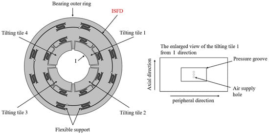
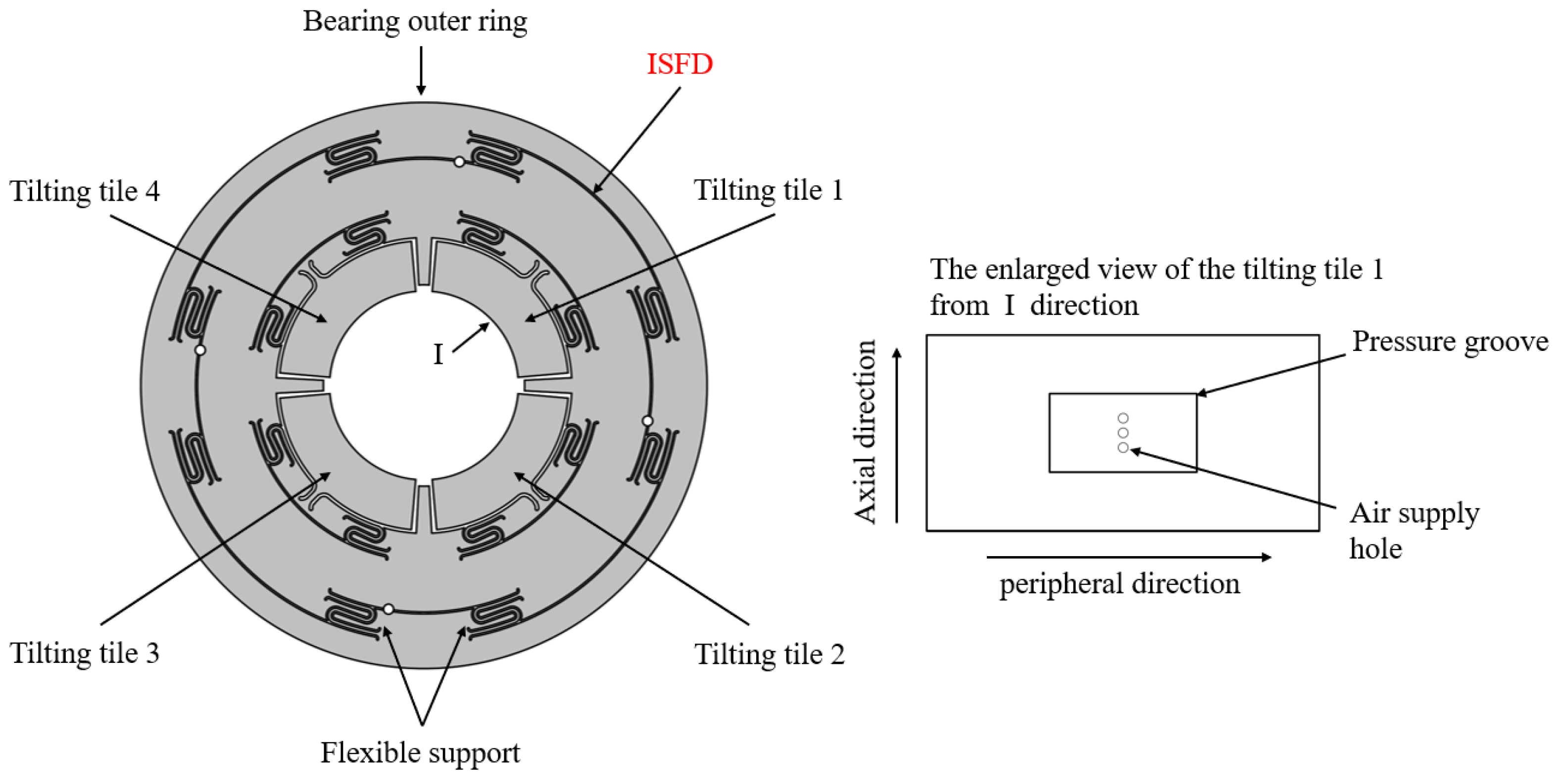
The air static pressure tilting-pad bearing structure integrated with ISFD used in this article is shown in Figure 1. It consists mainly of tilting pads, a flexible support structure, ISFD, and the outer ring of the bearing. The system adopts a dual-fluid configuration: compressed air is used as the lubricating and load-carrying medium for the aerostatic tilting-pad bearing, whereas lubricating oil is used as the working fluid in the ISFD to generate squeeze-film damping. This design integrates the squeeze oil film damper with the bearing body, making the structure more compact and providing more efficient damping performance, which helps to reduce vibration and improve system stability. The enlarged view on the right side of Figure 1 clearly shows that a static pressure cavity with a depth of 0.1 mm has been designed on the inner surface of the pad. The flexible support structure performs two key functions: On the one hand, it allows the blade to achieve limited radial oscillation to generate a wedge-shaped gas film; on the other hand, it can enhance its adaptability to rotor eccentricity through its own elastic deformation and, to a certain extent, introduce stiffness and damping. The basic parameters of the bearings are shown in Table 1.
Figure 1.
Integrated aerostatic tilting-pad bearing with ISFD. The enlarged view "I" clearly shows the Pressure groove.
Table 1.
Basic parameters of bearings.
2.2. The Damping Regulation Principle of ISFD
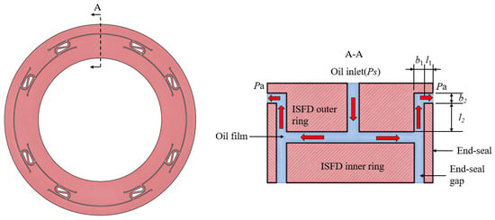
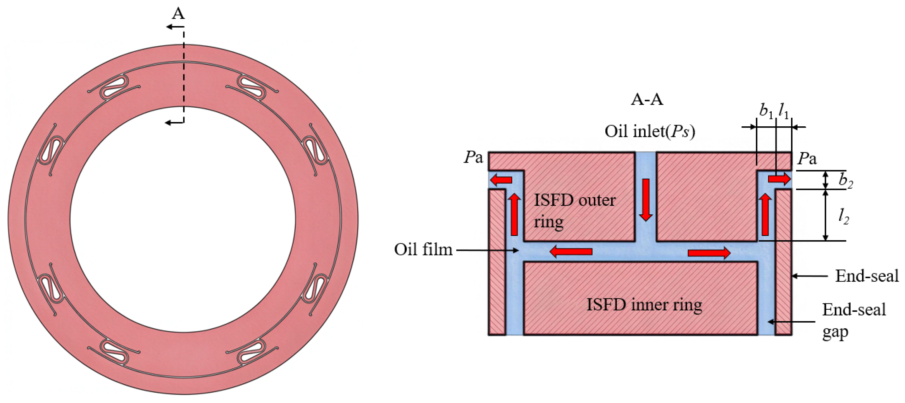
Figure 2 shows the sectional view of the ISFD with end-sealing. Lubricant is injected at supply pressure Ps to fill the arc oil film and flows laterally. A tiny axial sealing gap b1 over radial length l2 seals both ends of the oil film region to create high flow resistance; reducing b1 further raises axial resistance and improves damping. The oil flows radially outward first, turns axial at the outer seal diameter, and exhausts at ambient pressure Pa. Here b2 < b1 and l1 ≪ l2. The end-seal suppresses lubricant circumferential flow, forcing oil to drain only from the upper side. In Figure 2, the red arrow indicates the oil flow path within the ISFD.
Figure 2.
Sectional view of the integral extrusion oil film damper.
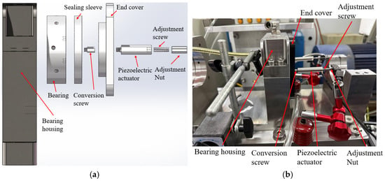
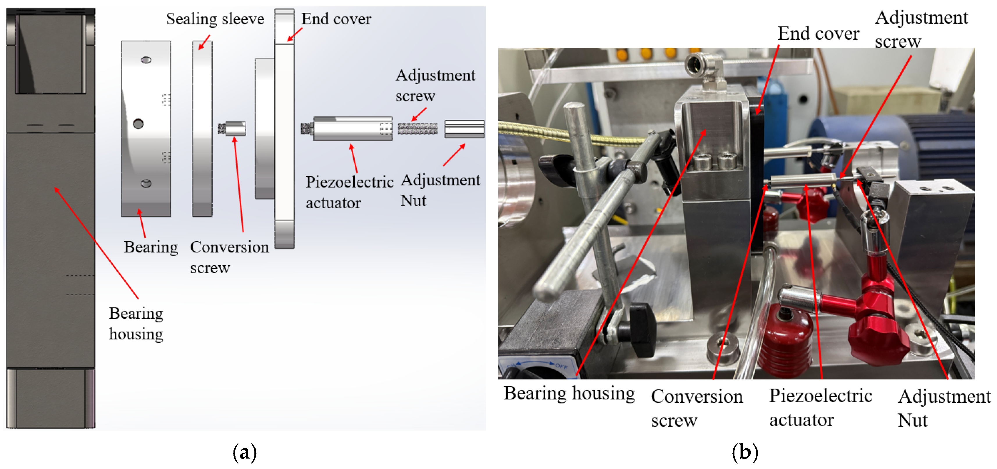
The end-seal gap of the ISFD is adjusted through a two-stage procedure consisting of threaded mechanical coarse adjustment and piezoelectric fine adjustment. In the present study, no closed-loop vibration-feedback control algorithm is employed. The piezoelectric actuator is driven by a prescribed voltage signal for fine adjustment of the end-seal gap. Based on the experimentally calibrated voltage–displacement relationship, the displacement output of the piezoelectric actuator can be regulated by adjusting the applied voltage, thereby changing the end-seal gap and consequently the damping characteristics of the ISFD. The schematic diagram of the piezoelectric adjustment mechanism for regulating the ISFD damping is shown in Figure 3.
Figure 3.
End-seal gap adjustment structure. (a) Structure diagram and (b) picture of real products.
This structure is composed of a seal sleeve, a cover, a piezoelectric actuator, adjusting screws, and adjusting nuts, etc. Among these, the sealing sleeve serves as the seal end and the protrusion. This paper proposes a method for dynamically adjusting the end-seal gap through piezoelectric actuators to achieve ISFD damping regulation. The influence of the damping-adjustable ISFD on the vibration characteristics of the aerostatic tilting-pad bearing–rotor system is investigated. The cover and the corresponding O-ring are responsible for the end-seal.
The adjustment process is divided into two steps. First, coarse adjustment is performed using the adjusting nut and screws to set the initial end-seal gap within the required range. Then, the end-seal gap is finely adjusted using the piezoelectric ceramic actuator by applying a prescribed driving voltage according to the experimentally calibrated voltage–displacement relationship. No closed-loop vibration-feedback control is employed in the present study. During the fine-adjustment procedure, the actuator voltage is changed in increments of 1 V, corresponding to a displacement increment of approximately 4.6 μm. After each adjustment, the driving voltage is maintained at a constant for approximately 10 s to allow the rotor–bearing system to reach a stable operating condition. The vibration response is then recorded for 0.8 s at the corresponding end-seal gap before the next adjustment is performed. The piezoelectric actuator used in this article is a low-voltage column-type piezoelectric ceramic, with the model number being PSt150/5/40VS10. It is internally equipped with low-voltage stacked ceramic components, and, externally, a cylindrical stainless-steel shell is used as the protective structure. The mechanical shell is used to apply preload to the internal stacked components. This actuator can operate stably under high-load and high-dynamic response conditions. Functionally, it can effectively output the displacement and thrust generated by the piezoelectric ceramic stack, and also has the ability to withstand certain tensile loads. Its specific performance indicators are shown in Table 2.
Table 2.
Performance parameters of piezoelectric actuators.
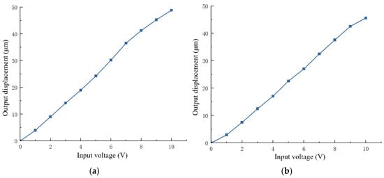
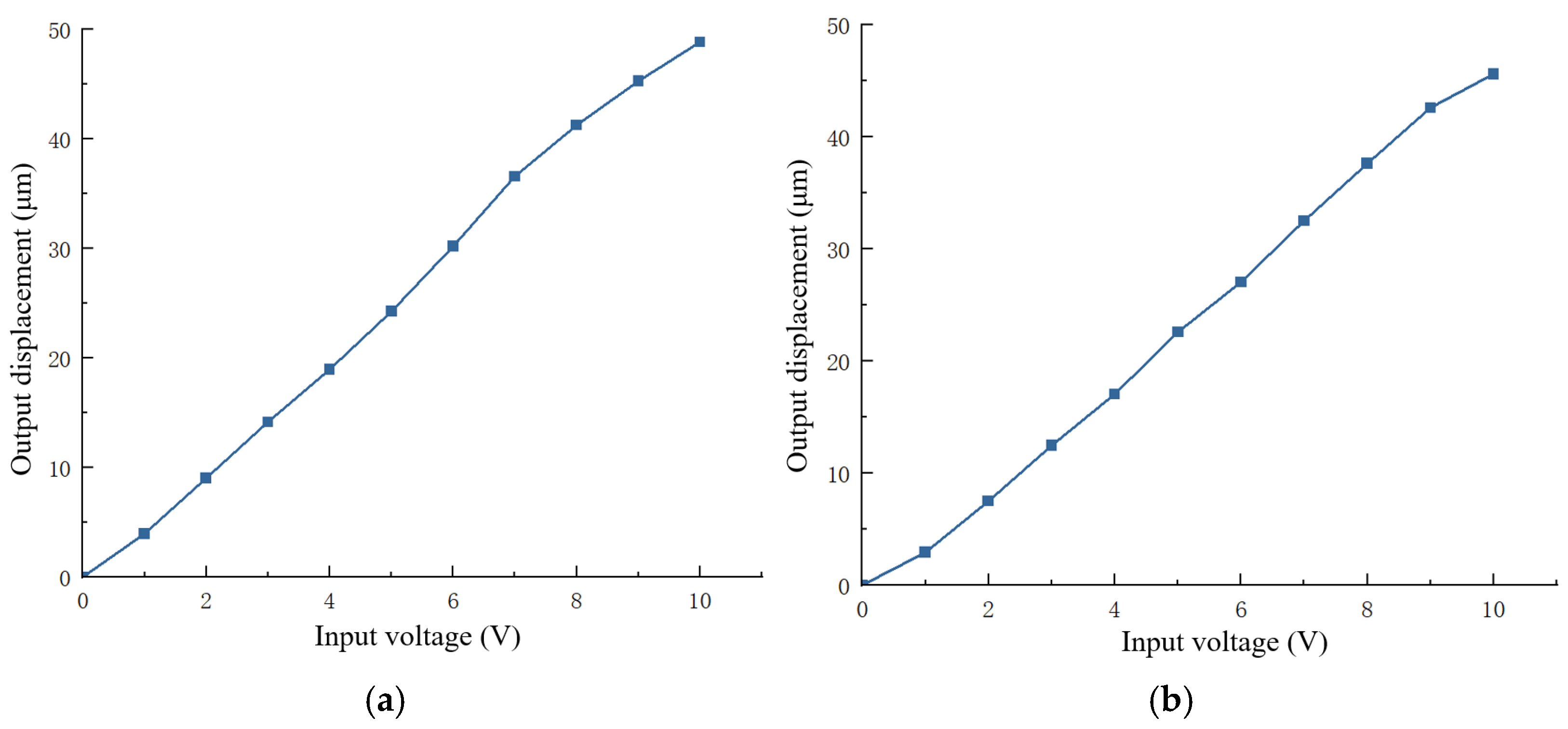
During the calibration process of the displacement of the piezoelectric actuator and the sleeve. The input voltage applied to the piezoelectric actuator was increased stepwise with an increment of 1 V. The displacement values measured by the displacement sensor under each voltage condition were recorded. Each set of data was measured three times, and the average value was taken to obtain the relationship curve between the output displacement of the piezoelectric actuator and the input voltage.
From the displacement–voltage relationship curve in the Figure 4, it can be seen that the output displacements of the piezoelectric actuator and the sleeve both show a good approximate linear relationship with the input voltage.
Figure 4.
Curve of displacement and input voltage relationship: (a) curve of output displacement of the piezoelectric actuator and input voltage and (b) curve of output displacement of the sleeve and input voltage.
Hysteresis, creep, and preload dependence may cause deviations from the calibrated displacement. As the actuator is used for stepwise gap adjustment rather than high-frequency vibration tracking, its dynamic-response limitation has little influence on the present experiments. These effects may introduce small deviations in the end-seal gap adjustment.
2.3. Bearings—Rotor Test Rig
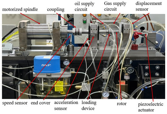
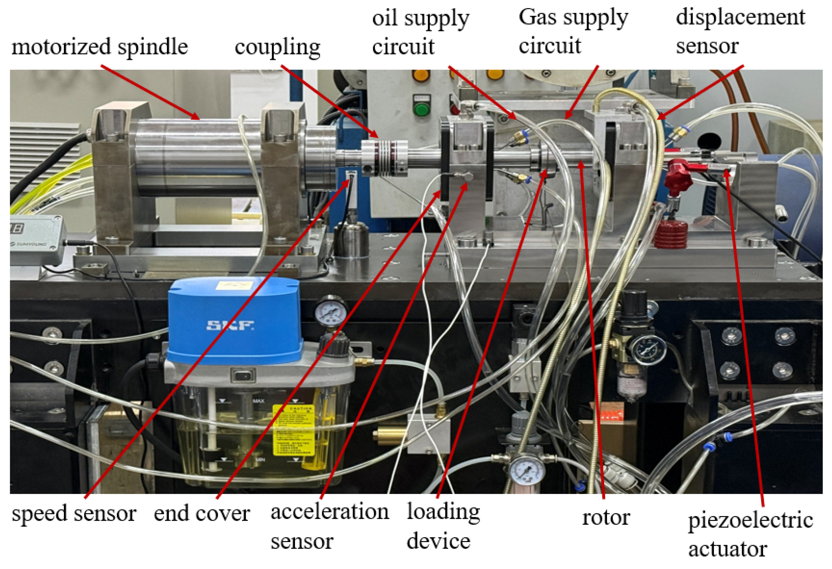
To investigate how ISFD damping regulation affects bearing–rotor stability, this work builds an air bearing–rotor test rig (Figure 5). The rig consists of a high-speed motor spindle, flexible coupling, bearing housing, seal end cover, loading unit, sensors, and air and oil supply systems. Mounted on an adjustable base with water cooling, the spindle supports rotational speeds from 0 to 20,000 r/min. Although the test rig is capable of operating at speeds up to 20,000 r/min, the rotor experiments in the present study were conducted within a range of 3000–6000 r/min. This range was selected to investigate the influence of adjustable ISFD damping on the rotor vibration response under stable and repeatable operating conditions. The purpose of the present tests is to verify the effect of end-seal clearance adjustment rather than to identify the resonance characteristics or high-speed stability limit of the aerostatic bearing–rotor system. Therefore, the conclusions obtained from the rotating experiments are limited to the investigated rotational speed range.
Figure 5.
Bearing–rotor test rig.
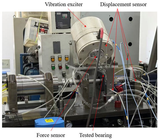
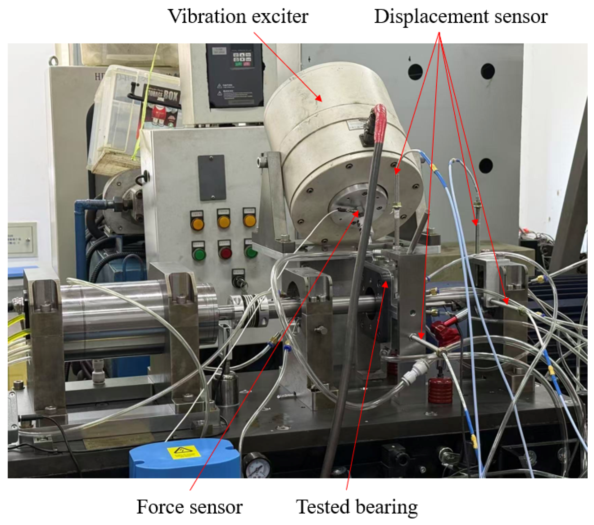
Based on the bearing–rotor experimental platform, the bearing excitation experimental platform was constructed. Its overall structure is shown in Figure 6. The core improvements mainly include the following four aspects: First, the test bearing and its sealing components were arranged in an inverted position and centered in the middle section of the rotating shaft as an independent object to be excited. Second, an electromagnetic exciter was added to apply the required dynamic alternating load to the middle test bearing. Third, a dynamic force sensor was added to monitor and record the dynamic excitation force output by the exciter in real time. Finally, two displacement sensors were added to synchronously measure the absolute displacement responses of the middle bearing and its sealing components in the horizontal and vertical directions. The JZQ-70 type electric exciter was selected as the loading source.
Figure 6.
Bearing excitation experimental platform.
To assess the stability of the bearing–rotor system during operation, the relative position between the bearing and the rotating shaft was measured. The sensor used was the PX series manufactured by Hunan Taiwei Da Shi Technology Co., Ltd. (Xinma Power Innovation Park, No. 899, Xianyue Ring Road, Tianyuan District, Zhuzhou, China), which features high sensitivity, excellent accuracy, and good durability. Its output voltage range is 0–5 V, and the measurement range is 1 mm. The acceleration sensor is used to monitor the vibration response transmitted from the rotor to the bearing and the bearing housing in real time. In this paper, two acceleration sensors are installed at the base position of the bearing housing at the far end of the motor, detecting the vibration signals in the vertical and horizontal directions, respectively. The piezoelectric acceleration sensor selected in this paper is of the ICP type with an internal signal conditioning circuit, and its model is PCB 352C33, with a sensitivity of 100 mV/g. To obtain the excitation force signal during the excitation experiment in real time, the 208C02 type PCB dynamic force sensor is chosen. The real-time acquisition of the experimental data in this paper is accomplished through the B&K acquisition system.
3. Experimental Results and Discussion
3.1. The Influence of End-Seal Gap Adjustment on the Damping Characteristics of ISFD Under Dynamic Excitation
To investigate the influence of the end-seal gap on the damping characteristics of the ISFD, dynamic excitation tests were conducted for three initial end-seal gaps of 0.1 mm, 0.2 mm, and 0.3 mm. During the excitation tests, the excitation force, the absolute displacement responses of the bearing in the horizontal and vertical directions, and the relative displacement between the bearing and the rotor were synchronously acquired in the time domain. The measured signals were then transformed into the frequency domain using the fast Fourier transform (FFT), while retaining both the amplitude and phase information at the prescribed excitation frequency.
The frequency-domain dynamic equilibrium equation can be expressed as
where , is the excitation angular frequency, is the mass matrix, is the complex amplitude vector of the excitation force, is the absolute displacement vector of the bearing, and is the relative displacement vector between the bearing and the rotor. and denote the equivalent stiffness and damping matrices, respectively.
For each excitation frequency, the complex amplitudes of the excitation force and displacement responses were extracted from the FFT results. The corresponding complex dynamic impedance is expressed as
Accordingly, the stiffness and damping coefficients are determined from the real and imaginary parts of the complex dynamic impedance as
The above procedure was applied to the measured excitation data at each prescribed excitation frequency to obtain the corresponding dynamic characteristic coefficients of the ISFD.
Under oil-supplied conditions, dynamic excitation tests were conducted to investigate the effects of three initial end-seal gaps (0.1 mm, 0.2 mm, and 0.3 mm) on the damping characteristics of the ISFD. The rotor was kept stationary, while a harmonic excitation force with a constant amplitude of 20 N was applied at excitation frequencies of 20 Hz, 40 Hz, and 60 Hz. Although the rotor did not rotate during the tests, the external dynamic excitation induced periodic squeeze motion of the lubricating oil film, allowing the equivalent dynamic damping characteristics of the ISFD to be identified. Previous experimental studies have also demonstrated that shaft rotation is not required for the identification of ISFD dynamic force coefficients [18]. In the present identification process, the bearing housing is simplified as a rigid body; therefore, the damping coefficients obtained from the oil-supplied dynamic excitation tests are used to characterize the equivalent damping of the ISFD. Table 3 summarizes the variation in the identified ISFD damping coefficients with excitation frequency for the three initial end-seal gaps. Future experimental work will include repeated measurements under representative operating conditions to further assess the repeatability and reliability of the experimental results.
Table 3.
The ISFD damping coefficient (N·s/m) under different working conditions.
Table 3 reveals that damping coefficients rise markedly with decreasing initial end-seal gaps at identical excitation frequencies, showing distinct nonlinear damping growth. Reducing the gap from 0.2 mm to 0.1 mm yields a far larger damping increment than narrowing it from 0.3 mm to 0.2 mm. This arises because the seal gap governs the axial leakage resistance of the ISFD; smaller gaps strengthen end-face throttling, curb oil leakage, build higher oil-film hydrodynamic pressure, and greatly boost the system’s vibration energy dissipation capacity.
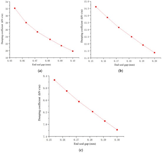
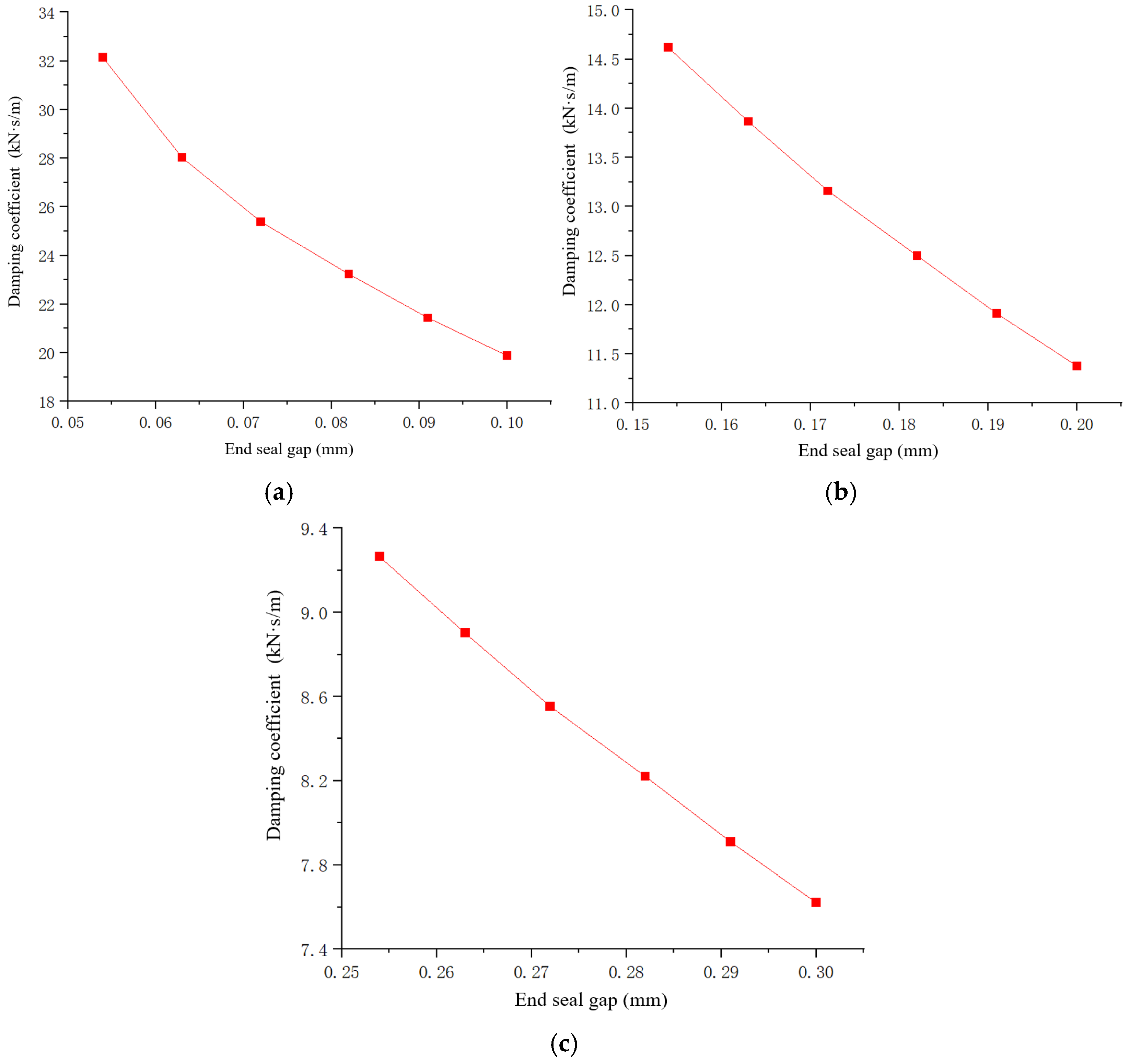
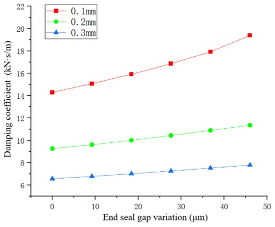
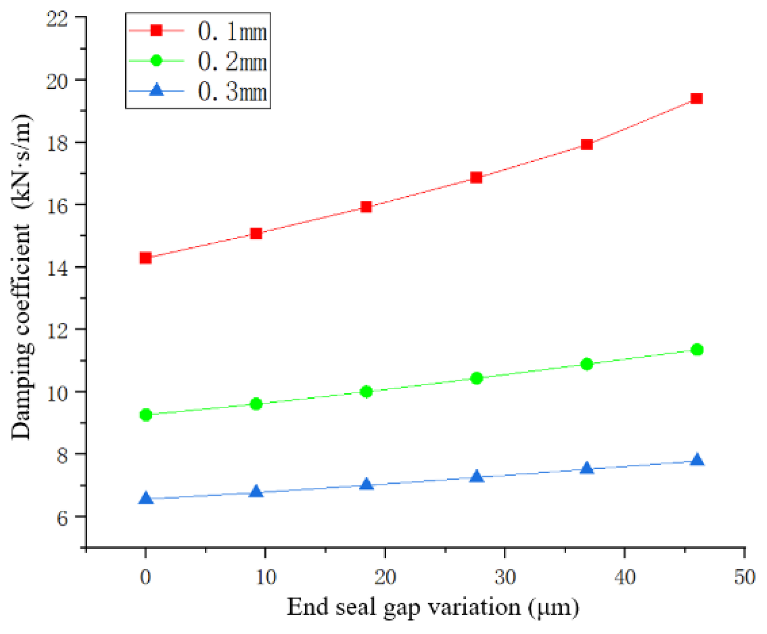
To further explore the specific impact of the dynamic adjustment of the end-seal gap on the damping performance of ISFD, this paper takes the excitation frequency of 20 Hz as an example and gradually reduces and fine-tunes the initial end-seal gap. The influence of the gap size on the damping coefficient of ISFD is also measured. The specific results are shown in Figure 7.
Figure 7.
The influence of end-seal gap variation at an excitation frequency of 20 Hz on the damping coefficient of ISFD: (a) initial end-seal gap: 0.054–0.1 mm; (b) initial end-seal gap: 0.154–0.2 mm; (c) initial end-seal gap: 0.254–0.3 mm.
As shown in Figure 7, as the end-seal gap is adjusted to continuously reduce the actual gap, the damping coefficient exhibits a clear upward trend under all initial gap conditions. However, this increase is not a simple linear growth. With the same adjustment amount, when the initial gap decreases from 0.1 mm to 0.054 mm, the damping coefficient curve rises most steeply; whereas when the initial gap decreases from 0.3 mm to 0.254 mm, the increase in the damping coefficient curve is relatively gentle. This phenomenon confirms the nonlinear modulation effect of face seal gap on the damping coefficient. From a physical mechanism perspective, reducing the face seal gap directly increases the flow resistance of axial lubricant leakage. When the initial gap is already small (e.g., 0.1 mm), further reduction imposes stricter constraints on face leakage, enabling faster accumulation of hydrodynamic pressure within the squeeze film.
During the actual operation of the rotor, the overall dynamic characteristics of the rotor–bearing system are jointly influenced by the aerostatic gas film and the squeeze-film effect of the lubricating oil in the ISFD. The equivalent damping coefficient of the bearing is obtained through coupled calculation by combining the theoretically calculated dynamic coefficients of the aerostatic gas film with the stiffness and damping coefficients of the ISFD identified from the dynamic excitation experiments described above. The coupling formulation adopted in the present study is based on the flexible-support model proposed by [22], in which the fluid-film bearing is connected in series with an equivalent support characterized by stiffness, damping, and mass. The calculation formula for the equivalent damping coefficient is as follows:
In the above equations, represents the gas film stiffness coefficient, N/m, obtained from the theoretical calculation of the aerostatic gas film; is the stiffness coefficient of the ISFD measured in the excitation experiment, in N/m, obtained from the dynamic excitation experiments described above; is the gas film damping coefficient, N·s/m, obtained from the theoretical calculation of the aerostatic gas film; is the damping coefficient of the ISFD, N·s/m, obtained from the dynamic excitation experiments described above; is the equivalent mass of moving support components associated with the ISFD, including the bearing and sealing end covers, and is calculated from the corresponding CAD model, kg; N is the operating speed, r/min; and is the operating angular velocity of the rotor, in rad/s.
As shown in Table 3, the identified ISFD damping coefficient varies only slightly over the tested excitation frequencies of 20, 40, and 60 Hz, which is consistent with the weak frequency dependence reported by Ertas et al. [23]. Therefore, was treated as an approximately frequency-independent parameter in the subsequent rotating-system calculations. Specifically, the damping coefficient identified at 20 Hz was adopted as the representative value for all operating speeds from 3000 to 6000 r/min, without interpolation or extrapolation to the corresponding synchronous frequencies.
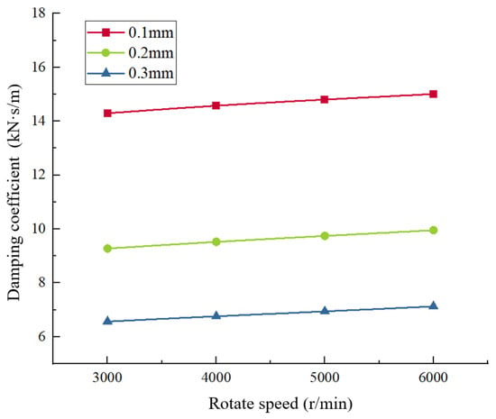
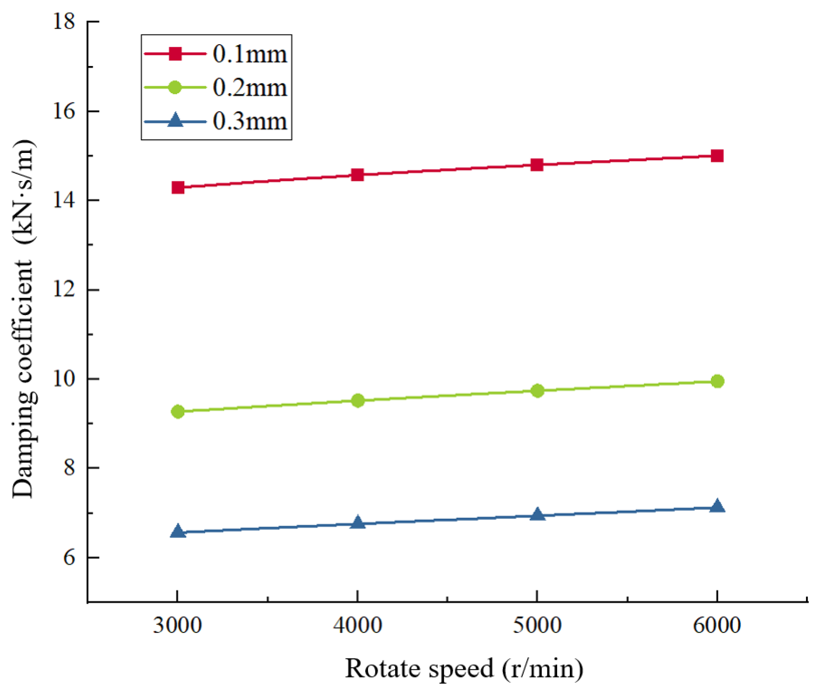
Within the speed range of 3000 r/min to 6000 r/min, the bearing film pressure is mainly influenced by the static pressure effect, and the dynamic pressure effect is relatively weak. The supply pressure of gas to the bearing support ring is set at 0.1 MPa, while that to the non-supporting ring is 0.05 MPa. The calculation results of the dynamic characteristic coefficients of the film at each speed condition are shown in Table 4. The dynamic characteristic coefficients of the ISFD obtained under the dynamic excitation condition were substituted into the above formula along with the gas film dynamic characteristic coefficients for coupled solution. The overall equivalent damping coefficient of the ISFD-tilting pad bearing calculated in this way is shown in Figure 8 and Figure 9.
Table 4.
The dynamic characteristic coefficients of the gas film at different rotational speeds.
Figure 8.
The equivalent damping coefficient of the ISFD-tilting pad bearing under different rotational speeds after coupling.
Figure 9.
The equivalent damping coefficient of the ISFD-tilting pad bearing at 3000 r/min changes as the end-seal gap decreases.
From the coupling calculation results shown in Figure 8 and Figure 9, it can be observed that the introduction of the air film effect leads to a significant decrease in the equivalent damping coefficient of the bearing when compared with the independent ISFD damping. Among them, when the initial end-seal gap is 0.1 mm, the attenuation amplitude of the damping coefficient is the most obvious. Under different initial end-seal gap conditions, the coupled equivalent damping coefficient shows a slight upward trend with the increase in working speed. This phenomenon mainly results from the enhanced effect of the fluid dynamic pressure of the air film on the increase in rotational speed. By coupling the dynamic characteristic coefficients of the air bearing obtained through theoretical calculations with those of the ISFD obtained from experimental tests, it was found that the overall equivalent damping coefficient of the ISFD and the air bearing exhibited a trend of increasing as the end-seal gap decreased.
3.2. The Influence of Dynamically Adjusting the Damping Performance of the ISFD on the Vibration Response of the Rotor System
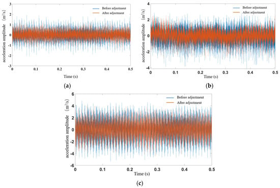
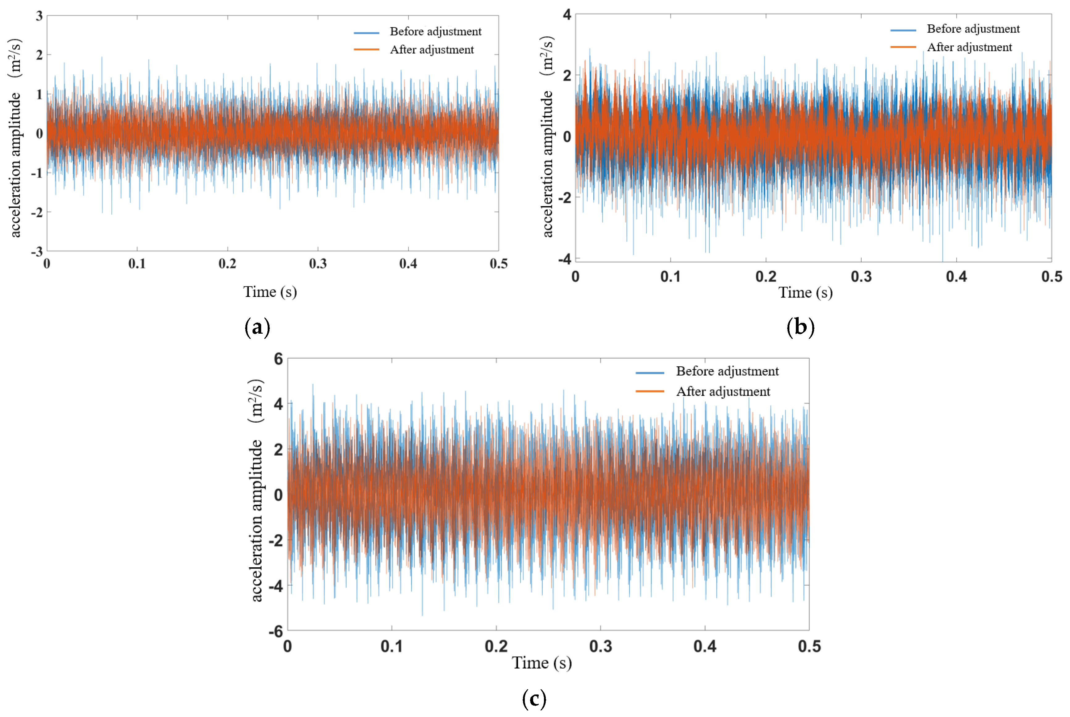
To directly evaluate the effect of piezoelectric end-seal gap adjustment on the vibration response of the rotor system, paired experiments were conducted under identical rotational speed and loading conditions. For each initial end-seal gap of 0.1 mm, 0.2 mm, and 0.3 mm, the rotational speed and bearing load were maintained at 6000 r/min and 19.8 N, respectively. The acceleration amplitude was first measured before piezoelectric adjustment, with the end-seal gap maintained at its preset initial value, which was taken as the fixed-gap baseline. A prescribed voltage was then applied to the piezoelectric actuator to adjust the end-seal gap, while the rotational speed and bearing load were kept unchanged, and the acceleration amplitude was measured again. Figure 10 therefore provides a direct comparison between the fixed-gap and piezoelectrically adjusted-gap states under the same operating condition. In the figure, the blue bars represent the acceleration amplitude before gap adjustment, whereas the orange bars represent the acceleration amplitude after gap adjustment.
Figure 10.
Comparison chart of the amplitude changes of the rotor system acceleration before and after different end-seal gap adjustments: (a) end-seal gap of 0.1 mm; (b) end-seal gap of 0.2 mm; (c) end-seal gap of 0.3 mm.
From the comparative analysis in Figure 10, it can be seen that for different end-seal gaps, reducing the end-seal gap through piezoelectric drive can reduce the vibration of the bearing and improve the operational stability of the rotor system. To more clearly display the specific change pattern of the acceleration amplitude during the gap reduction process, this paper extracted the average values of the acceleration amplitudes under different end-seal gaps during the regulation process for quantitative comparison. The results are shown in Table 5.
Table 5.
The variation of the acceleration amplitude of the rotor system during the process of regulating the damping of the seal gap at different initial end-seal gaps.
From Table 5, it can be seen that for the initial end-seal gaps of 0.2 mm and 0.3 mm, when the end-seal gap is further reduced, the trend of the amplitude changes of the accelerations shows a high degree of consistency. As the end-seal gap is gradually reduced step by step, the amplitude of the acceleration shows a stable and continuous monotonically decreasing trend. This indicates that within these two relatively large initial gap ranges, gradually reducing the gap can effectively enhance the end-face throttling limiting effect of the ISFD internal fluid, thereby providing continuous and positive damping benefits for the entire rotor system and achieving a stable vibration reduction effect.
To further assess the repeatability of the rotor vibration measurements, repeated experiments were conducted under representative test conditions. The measured acceleration amplitudes were 0.4992 ± 0.0034 m/s2 and 0.6544 ± 0.0078 m/s2 for the initial end-seal gaps of 0.1 and 0.2 mm, respectively, where the values are reported as mean ± standard deviation. The small standard deviations indicate good consistency of the repeated measurements.
However, for an initial end-seal gap of 0.1 mm, the acceleration amplitude no longer decreases monotonically as the end-seal gap is further reduced, but instead exhibits a decrease followed by an increase. This behavior can be attributed to the change in the dynamic characteristics of the squeeze film when the end-seal gap becomes excessively small. As the end-seal gap decreases, axial lubricant leakage is initially restricted, which enhances the squeeze-film pressure and improves the damping effect of the ISFD. However, when the gap approaches the critical small-gap region, the lubricant becomes increasingly difficult to evacuate from the squeeze-film chamber during each oscillation cycle. The resulting fluid confinement enhances the influence of fluid compressibility and increases the pressure component associated with displacement, thereby producing an increase in the effective dynamic stiffness, i.e., a stiffness-hardening effect. Similar behavior has been reported for tightly sealed ISFDs, where restricted lubricant evacuation resulted in an increase in dynamic stiffness [18]. Therefore, the vibration response obtained for the end-seal gap of 0.1 mm indicates that reducing the end-seal gap does not necessarily lead to continuously improved vibration suppression. Once the gap is reduced beyond the optimum range, the additional damping benefit may be offset by the accompanying increase in effective dynamic stiffness, causing the vibration response of the rotor system to increase again.
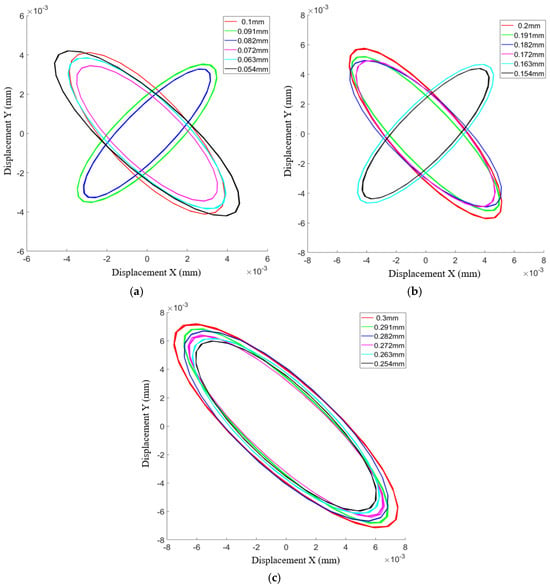
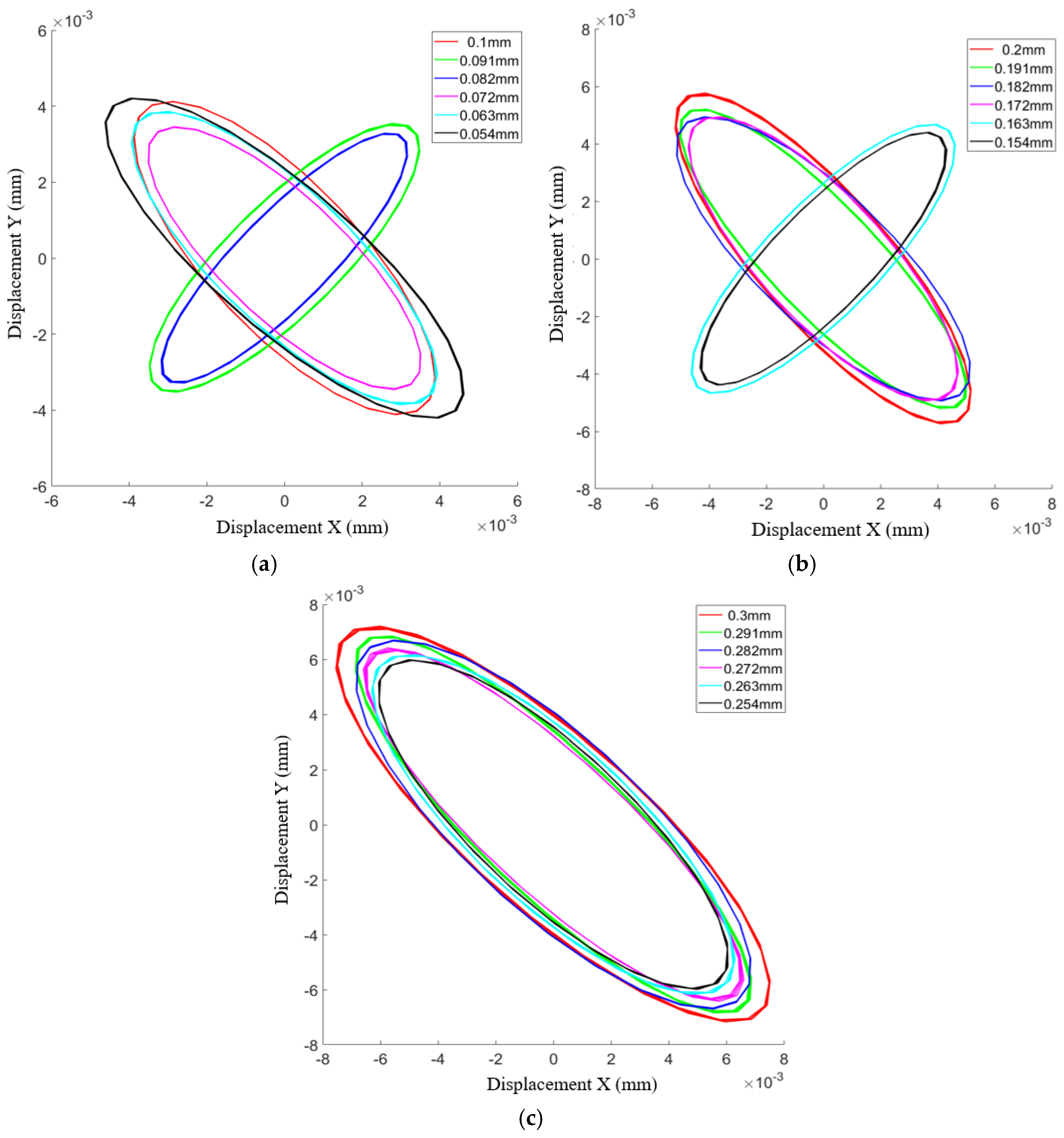
Figure 11 shows rotor shaft-center trajectories at a single-bearing load of 19.8 N and a rotational speed of 6000 r/min for initial end-seal gaps of 0.1, 0.2, and 0.3 mm. In each case, the end-seal gap is gradually reduced through piezoelectric actuation.
Figure 11.
Graph showing the variation of the rotor system’s shaft center trajectory during the process of regulating the damping of different initial end-seal gaps: (a) initial end-seal gap: 0.1 mm; (b) initial end-seal gap: 0.2 mm; (c) initial end-seal gap: 0.3 mm.
The shaft-center trajectory reflects the lateral whirling motion of the rotor journal, and its size provides a direct indication of the lateral vibration displacement of the rotor system. As shown in Figure 11, for initial end-seal gaps of 0.2 mm and 0.3 mm, the shaft-center trajectories progressively contract as the end-seal gap is reduced. Quantitative comparison shows that when the gap is reduced from 0.2 mm to 0.154 mm and from 0.3 mm to 0.254 mm, the major-axis diameter of the shaft-center orbit decreases by approximately 20.2% and 18.7%, respectively, while the enclosed orbit area decreases by approximately 37.8% and 28.6%, respectively. These results quantitatively confirm that an appropriate reduction in the end-seal gap can effectively suppress the lateral vibration displacement of the rotor.
For the initial end-seal gap of 0.1 mm, however, the shaft-center trajectory does not continuously contract as the gap is further reduced. The trajectory reaches its minimum size when the actual end-seal gap is approximately 0.08 mm and subsequently expands as the gap approaches 0.054 mm. Compared with the initial gap of 0.1 mm, the major-axis diameter and enclosed orbit area at 0.054 mm increase by approximately 12.7% and 7.0%, respectively. This result further indicates that a smaller end-seal gap is not necessarily better. When the gap becomes excessively small, the increased fluid confinement and the associated stiffness-hardening effect may offset the additional damping benefit, resulting in an increase in the rotor vibration response.
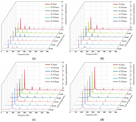
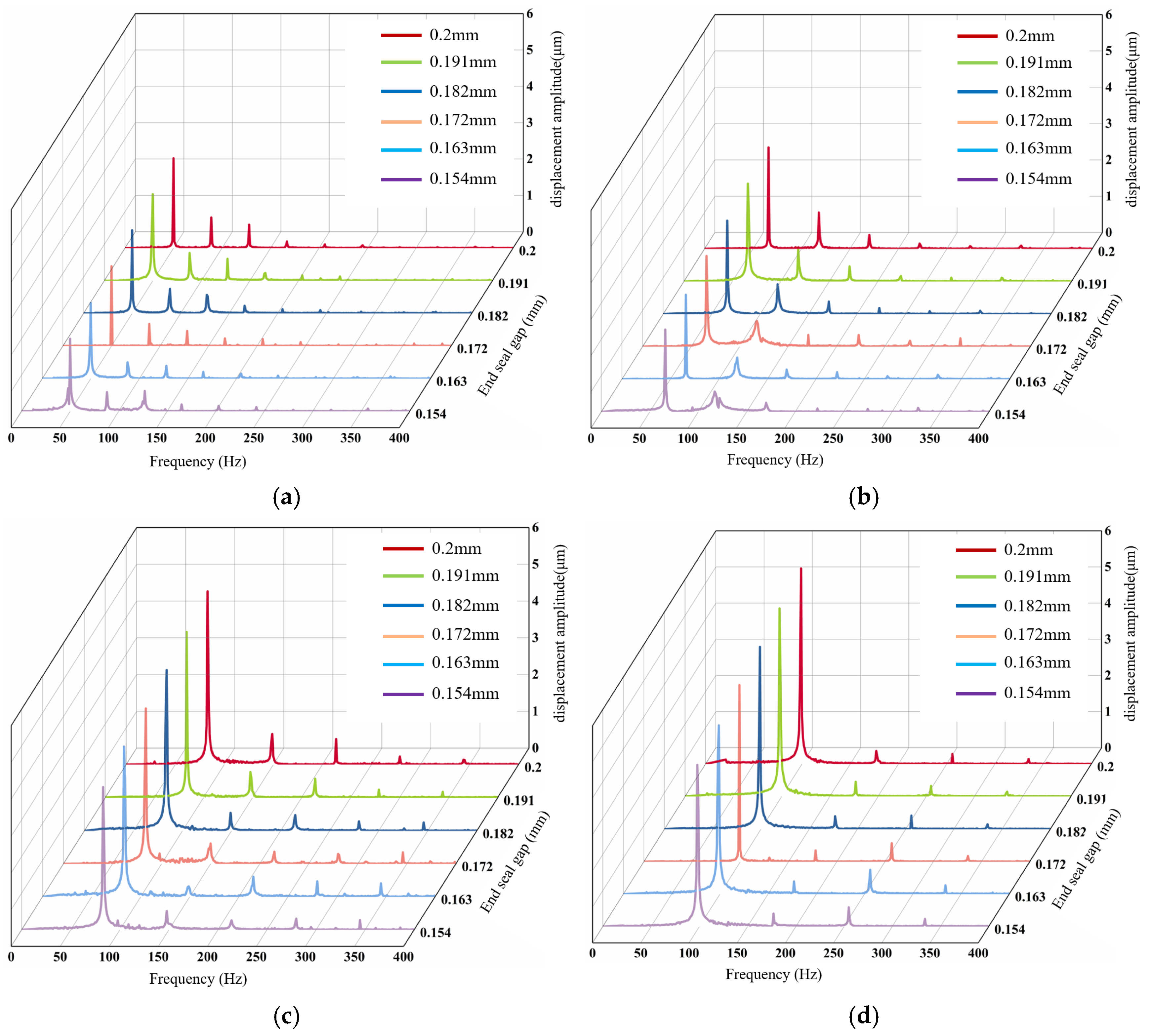
In order to explore the universality and differentiated performance of damping adjustment under different operating speeds, this paper takes an initial end-seal gap of 0.2 mm and a single bearing load of 19.8 N as an example. Using a piezoelectric actuator, the end-seal gap of the ISFD is reduced from 0.2 mm to 0.154 mm. Figure 12 summarizes the amplitude–frequency diagrams of the displacement signals of the rotor system within the speed range from 3000 r/min to 6000 r/min. Overall, within the entire tested speed range, the damping achieves dynamic adjustment to reduce the end gap, which is beneficial for reducing the vibration amplitude.
Figure 12.
The variation of displacement amplitude of the rotor system under different rotational speeds: (a) the working speed is 3000 r/min; (b) the working speed is 4000 r/min; (c) the working speed is 5000 r/min; (d) the working speed is 6000 r/min.
From the comparison of displacement amplitudes under different rotational speeds shown in Figure 12, it can be seen that in the operating ranges of 3000 r/min and 4000 r/min, due to the relatively low base vibration level of the system itself, the trend of displacement amplitude decrease is relatively gentle. However, in the two working conditions with relatively intense base vibrations at 5000 r/min and 6000 r/min, the trend of displacement amplitude decrease is more obvious. This indicates that when the rotor system is in a high-amplitude operating state, the increase in damping achieved through dynamic damping adjustment can achieve more significant vibration reduction benefits.
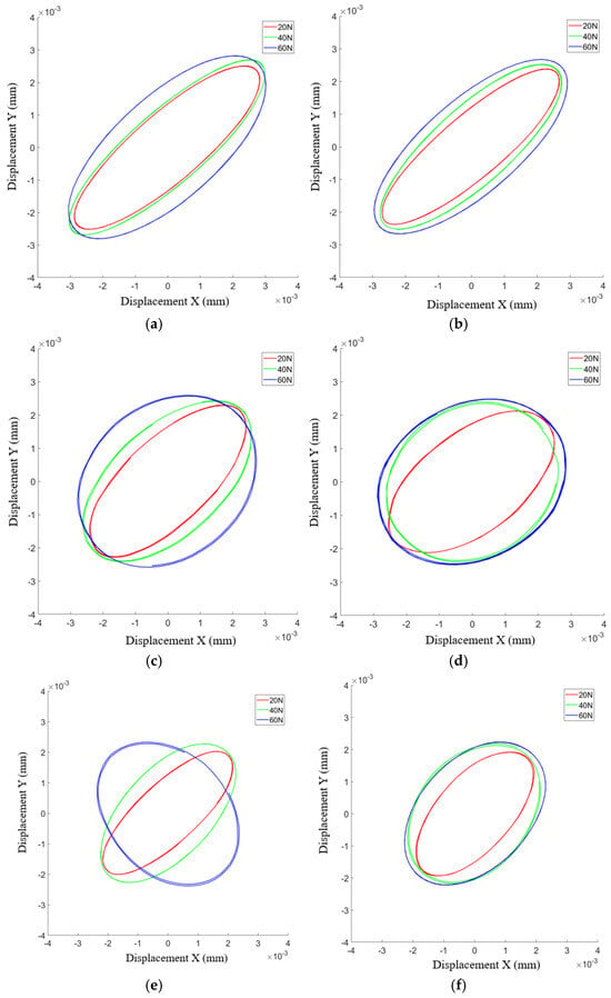
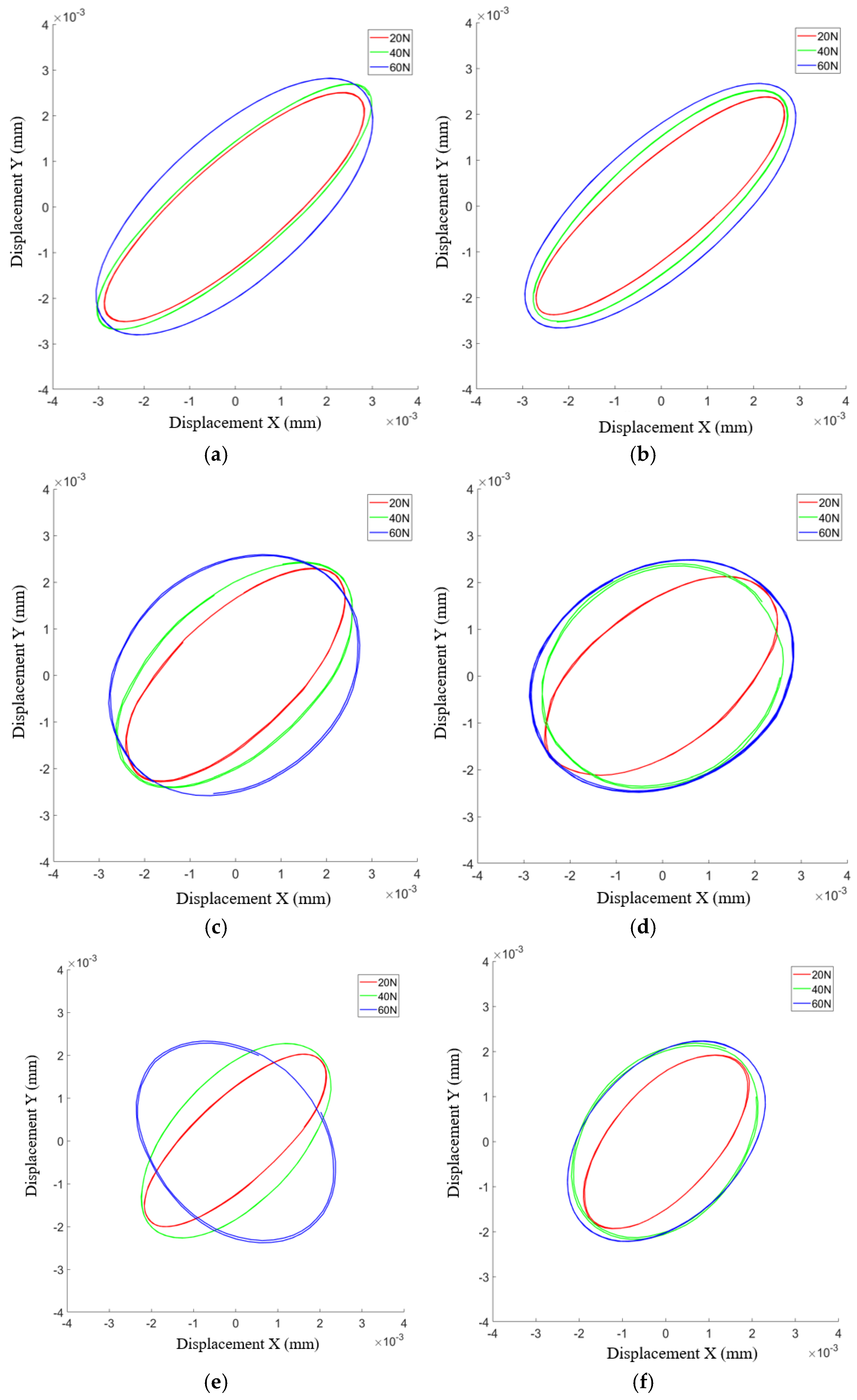
In order to investigate the vibration reduction efficiency of the damping dynamic adjustment method proposed in this paper under complex loading conditions, this paper takes the initial end-seal gap of 0.2 mm as an example. Through the piezoelectric actuator, the ISFD end-seal gap is adjusted from 0.2 mm to 0.154 mm. Different external load experiments are carried out, and three levels of external loads of 20 N, 40 N, and 60 N are selected. At a rotational speed of 3000 r/min, the vibration responses of the rotor system are compared and analyzed. Figure 13 shows the changes in the shaft center trajectory of the rotor system during the ISFD damping adjustment process at 3000 r/min under different loads.
Figure 13.
The changes in the shaft center trajectory of the rotor system under different loads: (a) end-seal gap: 0.2 mm; (b) end-seal gap: 0.191 mm; (c) end-seal gap: 0.182 mm; (d) end-seal gap: 0.172 mm; (e) end-seal gap: 0.163 mm; (f) end-seal gap: 0.154 mm.
As shown in Figure 13, reducing the end-seal gap from 0.2 mm to 0.154 mm leads to a clear contraction of the shaft-center trajectories under all three loading conditions. To quantitatively evaluate this change, the major-axis diameter of the approximately elliptical orbit was used as a representative measure of the orbit size. At 3000 r/min, the major-axis diameter decreased by approximately 27.3%, 24.4%, and 20.3% under external loads of 20 N, 40 N, and 60 N, respectively. These results quantitatively demonstrate that end-seal gap adjustment can reduce the lateral motion range of the rotor under different loading conditions. Although the reduction becomes less pronounced as the external load increases, a clear convergence of the shaft-center trajectory is still observed for all three loads.
4. Conclusions
This paper proposes a method for dynamically adjusting the end-seal gap through piezoelectric actuators to achieve regulation of ISFD damping. The influence law of the damping-adjustable ISFD on the vibration performance of the air static pressure tilting pad bearing–rotor system is investigated. The experimental results indicate that end-seal gap adjustment has the potential to improve the vibration attenuation performance of the bearing and the operational stability of the rotor system under the investigated operating conditions. As systematic repeated measurements were not performed for the rotor vibration tests, these results are mainly intended to demonstrate the observed vibration-response trend, while the quantitative magnitude of the reported vibration reduction should be interpreted with appropriate caution. The following conclusions are drawn:
(1) The ISFD damping regulation method combining mechanical coarse adjustment and piezoelectric fine adjustment is adopted. The initial end-seal gap is set by adjusting the nut and the adjusting screw. Then, during the experiment, the piezoelectric actuator precisely adjusts the end-seal gap to regulate the ISFD damping.
(2) Experimental studies have shown that when the end-seal gap is excessively compressed (in this experimental case, the end-seal limit gap is less than 0.08 mm), the fluid discharge channel becomes blocked under extremely small gaps, which will trigger the nonlinear enhancement effect of the squeezed oil film, resulting in a nonlinear rebound of the vibration response.
(3) By coupling the gas film dynamic characteristics with the measured ISFD dynamic characteristics, the overall equivalent dynamic characteristics of the ISFD–air bearing system were obtained. The calculation results show that reducing the end gap of the ISFD can effectively increase the damping of the system.
(4) The measured results indicate that reducing the end-seal gap within an appropriate range restricts the axial leakage of the lubricating oil and enhances the damping effect of the ISFD, thereby reducing the vibration response of the rotor–bearing system. However, when the end-seal gap is reduced below the optimum value and approaches the critical small-gap region, further reduction leads to an increase in the vibration response. These results demonstrate that an optimum end-seal gap exists and that effective vibration suppression can be achieved only within an appropriate gap-adjustment range.
(5) Regarding the phenomenon of increased vibration caused by the increase in damping observed in the experiment, further research on the dynamic behavior of the ISFD–air bearing rotor will be conducted in the future.
Author Contributions
Conceptualization, X.L. and X.W.; methodology, G.C. and G.X.; software, D.Z.; validation, G.C., G.X. and S.Y.; formal analysis, D.Z. and X.L.; investigation, G.X.; resources, X.W.; data curation, S.Y.; writing—original draft preparation, D.Z.; writing—review and editing, D.Z. and X.W.; visualization, X.L.; supervision, X.W. and S.Y.; project administration, G.C.; funding acquisition, X.W. All authors have read and agreed to the published version of the manuscript.
Funding
The present work is supported by the National Natural Science Foundation of China (Grant No. 52075311) and the Shanghai Key Laboratory of Intelligent Manufacturing and Robotics.
Data Availability Statement
The datasets generated and/or analyzed during the current study are available from the corresponding authors on reasonable request.
Conflicts of Interest
Author Gang Chen and Gaohui Xiao was employed by the company Shanghai Turbine Works Co., Ltd. The remaining authors declare that the research was conducted in the absence of any commercial or financial relationships that could be construed as a potential conflict of interest.
References
- Abdurrahim, D.; Tuncay, K. Pneumatic hammer instability in the aerostatic journal bearing–rotor system: A theoretical and experimental analysis. Proc. Inst. Mech. Eng. Part J J. Eng. Tribol. 2020, 235, 350650. [Google Scholar] [CrossRef] [Scilit]
- Nie, W.; Yang, X.; Li, J. Research progress on new structural squeeze film dampers of aero-engine in China. Sci. Technol. Eng. 2025, 19, 7909–7919. [Google Scholar]
- He, F.; Yang, T.; Ren, Y.; Zu, S.; Li, Y. Design of similarity method for rotor system with squeeze film damper. Mech. Syst. Signal Process. 2025, 240, 113423. [Google Scholar] [CrossRef] [Scilit]
- Zhang, Y.; Hou, L.; Wang, S.; Zhao, K.; Zhao, L.; Li, Q. Vibration reduction characteristics analysis and experimental study of staggered-type double elastic ring squeeze film damper under complex operating conditions. Mech. Syst. Signal Process. 2025, 235, 112919. [Google Scholar] [CrossRef] [Scilit]
- Chen, W.; Shi, H.; Li, J.; Chen, S. Vibration attenuation characteristics of squeeze film dampers in spiral bevel gear systems. Appl. Math. Model. 2023, 123, 136–158. [Google Scholar] [CrossRef] [Scilit]
- Zhang, Y.; He, L.; Yang, J.; Zhu, G.; Jia, X. Multi-Objective Optimization Design of a Novel Integral Squeeze Film Bearing Damper. Machines 2021, 9, 206. [Google Scholar] [CrossRef] [Scilit]
- Dong, H.; He, L.; Jia, X. Using Integral Squeeze Film Damper to Suppress Vibration of Gas Turbine. J. Vib. Eng. Technol. 2022, 11, 3163–3176. [Google Scholar] [CrossRef] [Scilit]
- Wang, P.; Chen, B.; Li, J.; Wang, J.; Zhang, Y. Novel aerostatic bearings with hermetically squeeze film dampers for the improvement of stability: Theoretical and experimental investigations. Precis. Eng. 2024, 85, 263–278. [Google Scholar] [CrossRef] [Scilit]
- Li, J.; Huang, J.; Han, S.; Wang, P.; Li, W. A novel active recess compensation aerostatic thrust bearing with hermetic squeeze film damper: Theoretical and experimental investigation. Mech. Syst. Signal Process. 2025, 224, 112207. [Google Scholar] [CrossRef] [Scilit]
- Wang, J.; Han, S.; Zhang, H.; Li, H.; Wang, P. Experimental and theoretical investigation on rotodynamic characterization of porous tilting pad bearings with hermetic squeeze film dampers. Mech. Syst. Signal Process. 2024, 218, 111548. [Google Scholar] [CrossRef] [Scilit]
- Hao, Y.; Zheng, C.; Wang, X.; Chen, C.; Wang, K. Damping characteristics of integral squeeze film dampers on vibration of deep groove ball bearing with localized defects. Ind. Lubr. Tribol. 2020, 73, 238–245. [Google Scholar] [CrossRef] [Scilit]
- Qin, X.; Wang, X.; Qiu, Z.; Hao, Y.; Zhu, Y. Experimental investigation for novel hybrid journal bearing with hydrostatic squeeze film and metal mesh damper in series. Ind. Lubr. Tribol. 2023, 75, 1–8. [Google Scholar] [CrossRef] [Scilit]
- Weissbacher, C.; Wieschalla, M.; Bauer, K. Integration of a Squeeze Film Damper in the Journal Bearing of a High-Speed Electric Motor. In Proceedings of the ASME Turbo Expo 2025:Turbomachinery Technical Conference and Exposition, Memphis, TN, USA, 16–20 June 2025; p. 8. [Google Scholar]
- Liang, Y.; Dong, X.; Ao, W.; Ni, Y. A Novel Application of Magnetorheological Seat Suspension with an Improved Tuning Control Strategy. Struct. Control Health Monit. 2023, 2023, 3985363. [Google Scholar] [CrossRef] [Scilit]
- Iacobellis, V.; Behdinan, K.; Chan, D.; Beamish, D. Effect of hole feed system on the response of a squeeze film damper supported rotor. Tribol. Int. 2020, 151, 106450. [Google Scholar] [CrossRef] [Scilit]
- Yan, W.; Lu, J.; Pan, J.; Liu, J. Research on dynamic characteristic coefficients of integral squeeze film damper. Machines 2024, 12, 274. [Google Scholar] [CrossRef] [Scilit]
- San Andrés, L.; Rodríguez, B. On the Experimental Dynamic Force Performance of a Squeeze Film Damper Supplied Through a Check Valve Sealed with O-Rings. J. Eng. Gas Turbines Power 2021, 143, 111011. [Google Scholar] [CrossRef] [Scilit]
- Lu, X.; San Andrés, L.; Koo, B.; Tran, S. On the effect of the gap of end-seals on force coefficients of a test integral squeeze film damper: Experiments and predictions. J. Eng. Gas Turbines Power 2021, 143, 011014. [Google Scholar] [CrossRef] [Scilit]
- Liu, Q.; Ouyang, W.; Wan, G.; Xiao, G. Theoretical and Experimental Investigation of Dynamic Characteristics in Propulsion Shafting Support System with Integrated Squeeze Film Damper. Lubricants 2025, 13, 335. [Google Scholar] [CrossRef] [Scilit]
- Lu, X.; San Andrés, L.; Koo, B. On the Influence of the Lubricant Feed Orifice Size and End Plate Seals’ Clearance on the Static and Dynamic Performance of Integral Squeeze Film Dampers. In Proceedings of the 11th IFToMM International Conference on Rotordynamics, Beijing, China, 18–21 September 2023; Springer: Cham, Switzerland, 2024; pp. 173–189. [Google Scholar]
- Jeung, S.; San Andrés, L.; Den, S.; Koo, B. Effect of Oil Supply Pressure on the Force Coefficients of a Squeeze Film Damper Sealed with Piston Rings. J. Tribol. 2019, 141, 061701. [Google Scholar] [CrossRef] [Scilit]
- Nicholas, J.; Barrett, L. The effect of bearing support flexibility on critical speed prediction. ASLE Trans. 1986, 29, 329–338. [Google Scholar] [CrossRef] [Scilit]
- Ertas, B.; Delgado, A.; Moore, J. Dynamic Characterization of an Integral Squeeze Film Bearing Support Damper for a Supercritical CO2 Expander. J. Eng. Gas Turbines Power 2018, 140, 052501. [Google Scholar] [CrossRef] [Scilit]

Disclaimer/Publisher’s Note: The statements, opinions and data contained in all publications are solely those of the individual author(s) and contributor(s) and not of MDPI and/or the editor(s). MDPI and/or the editor(s) disclaim responsibility for any injury to people or property resulting from any ideas, methods, instructions or products referred to in the content. |
© 2026 by the authors. Licensee MDPI, Basel, Switzerland. This article is an open access article distributed under the terms and conditions of the Creative Commons Attribution (CC BY) license.