


Abstract
Ferromagnetic–ferroelectric bilayers capable of strong zero-bias magnetoelectric (ME) coupling are critical for device miniaturization. Here, we report a self-biased ME response achieved in a bilayer structure consisting of lead zirconate titanate (PZT) and a dual-phase ferromagnetic composite. The composite consisted of hard barium hexaferrite (BaFe12O19) (BaM), which provides a high built-in magnetocrystalline anisotropy field, and soft nickel zinc spinel ferrite (Ni0.8 Zn0.2 Fe2O4) (NZFO) to ensure high magnetostriction compliance. Samples of (100 − x) wt.% BaM − x wt.% NZFO (BNZx) were synthesized via conventional solid-state sintering, with phase purity confirmed by X-ray diffraction. Magnetic characterization revealed substantial in-plane anisotropy fields (HA) ranging from 4.8 kOe to 8.3 kOe and a high saturation magnetostriction λ11 = −25 ppm. The ME voltage coefficient (MEVC) of the bilayers increased with higher spinel content, peaking at x = 90. Under zero external DC bias field, the BNZ90-PZT bilayer showed a low-frequency (=100 Hz) MEVC of 114 mV/cm Oe and a resonant (10.6 kHz) MEVC of 3.6 V/cm Oe. This strong self-biased coupling is driven by the BaM-provided internal magnetic flux, eliminating the need for external biasing elements and offering a practical framework for compact, bias-free sensors and energy harvesters.
1. Introduction
Multiferroic magnetoelectric (ME) composites, which combine distinct ferromagnetic and ferroelectric phases, offer a promising route toward controlling magnetic states via electric fields, and vice versa, through strain-mediated interfacial coupling [1,2,3,4,5]. In these systems, the overall ME conversion efficiency depends heavily on the product of the piezoelectric coefficient d and the piezomagnetic coefficient q = dλ/dH (where λ is the magnetostriction) [6]. A long-standing practical bottleneck for the use of ME composites in useful technologies, however, is the reliance on bulky, power-consuming external DC bias fields (H) to maximize q [1,2]. Eliminating this external bias requirement is critical if these materials are to be integrated into compact magnetic sensors, energy harvesters, or high-resolution imaging arrays [2,7,8]. Consequently, engineering “self-biased” ME structures that can deliver strong zero-bias ME coupling strengths has become a central focus in the field [9].
Past attempts to engineer self-bias have typically relied on complex structural or processing interventions. These include compositionally grading the magnetic phase [10,11,12,13,14], using thermal annealing to induce an exchange bias [15], exploiting hysteretic remanence [9], or built-in stress engineering [9]. While these methods work, they often introduce processing complications, material fatigue, or strict geometry constraints. A more straightforward solution is to introduce a magnetically hard phase with a high magnetocrystalline anisotropy field HA to act as a built-in magnetic bias [16]. M-type barium hexaferrite BaFe12O19 (BaM) is a prime candidate for this purpose due to its strong uniaxial anisotropy field (HA~18 kOe) and high remanence [17,18,19,20,21]. Yet a fundamental material trade-off limits its utility: while BaM provides an excellent internal bias, its saturation magnetostriction (λ~1–2 ppm) is very low, making pure BaM composites highly inefficient for strain transfer [22].
The need for high magnetostriction in the ferromagnetic phase can be achieved with a composite of BaM and soft spinel ferrites, such as nickel zinc ferrite (NZFO), with a much higher saturation magnetostriction than BaM (λ11~30 ppm) and high permeability, but they lack self-biasing capabilities because of their soft magnetic nature [23,24,25]. The specific choice of the Ni0.8Zn0.2Fe2O4 stoichiometry is due to its high piezomagnetic sensitivity, particularly in low fields. Partial zinc substitution in nickel ferrite modifies the magnetic exchange coupling, increasing the saturation magnetization while lowering the coercivity and magnetic saturation threshold. This combination maximizes the low-field piezomagnetic coefficient (q = dλ/dH), enabling strong mechanical responses under a self-bias provided by BaM.
Interestingly, while such hard/soft ferrite composites have been widely investigated, the literature has focused almost exclusively on exchange-spring interactions in nanoscale systems aimed at optimizing permanent magnet performance [26,27,28,29,30]. The cooperative use of these two phases to deliberately bypass the anisotropy–magnetostriction trade-off in bulk ME structures has been largely overlooked. Specifically, the physics of decoupling these phases at a microstructural scale—retaining high bulk-like anisotropy while ensuring efficient strain transfer across a ferroelectric interface—remains unaddressed.
Here, we report the results of our studies on ME coupling in a bilayer of PZT and a platelet of a bulk ferromagnetic composite with micron-sized BaM and NZFO. The primary objective of this work is to engineer an ME structure with strong self-biased ME cross-coupling by deliberately avoiding the nanometer-scale exchange-coupling regime. By maintaining separate microscale domains, we preserve the large macroscopic anisotropy fields needed to establish an internal magnetic bias, while simultaneously achieving a high magnetostrictive strain compliance with the soft spinel phase [31]. This structural distribution allows the internal flux of the hard phase to bias the soft phase without dampening its magnetoelastic compliance, which we evaluate systematically across various weight fractions (x = 10–90). Polycrystalline, dual-phase ferromagnetic composites with (100 − x) wt.% BaM and x wt.% of NZFO (BNZx) (x = 10–90) were used in our study. The phase purity of the composites we prepared by ceramic techniques was confirmed by X-ray diffraction. The morphological features of the samples were examined by scanning electron microscopy (SEM). Magnetic characterization of the composites was done by magnetization (M) measurements, magnetostriction λ, and ferromagnetic resonance (FMR). The anisotropy field HA was determined from M vs. H as well as FMR data. Platelets of BNZx were bonded to lead zirconate titanate (PZT) to form bilayers, and the ME coupling strengths were measured by the ME voltage coefficient (MEVC) as a function of frequency and external bias H. We report an exceptional zero-bias MEVC at low frequencies and in electromechanical resonance modes. Details on the synthesis of the ferromagnetic composites, characterization, and results on ME measurements in bilayers with PZT are provided in the sections that follow.
2. Experiment
Conventional ceramic processing techniques were utilized to synthesize the ferrite composites. Initially, micrometer-sized polycrystalline powders of Ni0.8Zn0.2Fe2O4 and BaFe12O19 were prepared separately [17,32]. For NZFO synthesis, 99.9% pure NiO, ZnO, and Fe2O3 (all the chemicals procured from Alfa Aesar, Ward Hill, MA, USA) were weighed in stoichiometric proportions, ball-milled for 8 h, dried, and pre-sintered at 900 °C for 6 h. This was followed by a second ball-milling and sintering at 1200 °C. BaM powder was synthesized with 99.9% pure BaCO3 and Fe2O3 (procured from Alfa Aesar, Ward Hill, MA, USA) using a similar procedure, including sintering the powder at 1200 C. Composites of (100 − x) wt.% BaM and x wt.% NZFO, denoted by BNZx, where x = 10–90, in steps of 10, were prepared by mixing the individual ferrite powders in a ball mill for several hours and drying, and a 2 wt.% polyvinyl alcohol (PVA) solution was used as a binder. The mixtures were compacted in a die into disk-shaped pellets (diameter ≈ 18 mm; thickness ≈ 1.5 mm) under a uniaxial pressure of 250 MPa. The pellets were then sintered at 1250 °C for 6 h to ensure densification. Following sintering, the pellets were sliced into rectangular platelets and used for structural and magnetic characterization.
Structural characterization of the composites was performed using an X-ray diffractometer (Miniflex, Rigaku, Tokyo, Japan) and an SEM (JSM-6510/GS, JEOL, Tokyo, Japan). Magnetostriction λ as a function of in-plane static field H was measured on thin rectangular samples using a strain gage and a strain indicator (Model P3, Micro-Measurements, Wendell, NC, USA). A two-part epoxy (M-bond) was used to attach the strain gage. The magnetic field H was applied parallel to the length (direction-1) of the sample and the strain gage. The magnetostriction obtained in this configuration is designated as λ11. Magnetization as a function of H up to 2 T was measured on thin rectangular samples with a Physical Property Measurement System (PPMS, Quantum Design Inc., San Diego, CA, USA). Data were obtained for H parallel and perpendicular to the sample plane. Ferromagnetic resonance (FMR) measurements were carried out on thin rectangular platelets of the composites placed in an S-shaped coplanar waveguide. A 67 GHz vector network analyzer (E8361A, Agilent, Santa Clara, CA, USA) was employed to record the S21 vs. frequency f profiles for a series of H applied parallel to the sample plane.
Measurements of ME coupling strengths were performed on bilayers of BNZx and vendor-supplied PZT (PZT-850, American Piezo Ceramics, Mackeyville, PA, USA). Rectangular composite platelets of lateral dimensions 18 mm × 3 mm and 0.4 mm to 1 mm in thickness were epoxy-bonded to 0.3 mm thick PZT plates of similar lateral dimensions. The ME voltage coefficient (MEVC) measurements were made with the samples placed in an aluminum sample holder that was an effective RF shield to reduce noise pickup. The measurement system consisted of an electromagnet to apply a static field H and a pair of Helmholtz coils (placed inside the sample holder) to apply an AC magnetic field h. The AC voltage induced across the PZT layer was measured with a lock-in amplifier. The MEVC was measured as a function of H and the frequency f of the AC magnetic field, for H and h parallel to each other and either parallel or perpendicular to the sample plane.
3. Results
3.1. Structural Characterization
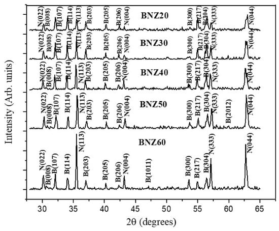
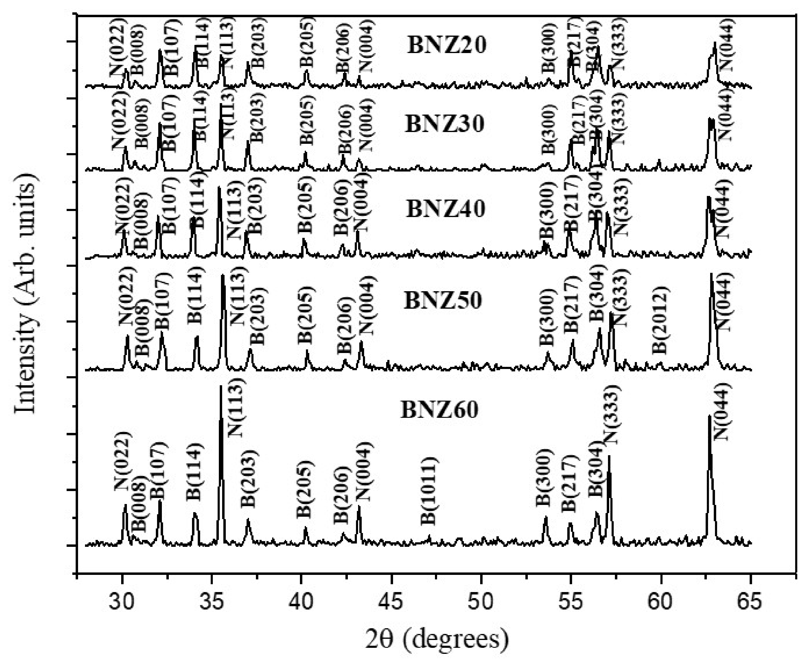
Figure 1 (for x = 20–60) and Supplementary Figure S1 (x = 10, 70–90 and pure BaM and NZFO) show the diffraction (XRD) patterns for the BNZx samples. All the diffraction peaks have been indexed and are consistent with the characteristic reflections of the hexagonal BaM and cubic spinel NZFO phases [17,32,33]. For BNZ20, the diffraction pattern is dominated by the BaM reflections due to its high BaM content, while only weak NZFO peaks are present. As the NZFO concentration increases from BNZ40 to BNZ50 and BNZ60, the intensity of the characteristic peaks for NZFO progressively increases, whereas those of BaM gradually decrease in intensity. We performed a semi-quantitative phase assessment based on relative intensity ratios and standard multi-phase linear peak-fitting using the MDI-JADE 6.0 software. The phase fractions of BaM and NZFO in the BNZx composites are listed in Table S1 in the Supplementary Material. Assuming a nominal ±5% error in the estimated values, there is overall good agreement between the estimated and expected phase fractions, except for BNZ20 and BNZ90, which are deficient in NZFO content.
Figure 1.
X-ray diffraction (XRD) patterns for magnetic composites with (100 − x) wt.% barium hexaferrite (BaM) and x wt.% of nickel–zinc ferrite (NZFO) for a series of x-values. The indexed reflections correspond to the hexagonal BaM and cubic spinel NZFO phases.
Past studies on the synthesis of polycrystalline BaM reported the presence of BaFe2O4, an impurity phase with either a hexagonal or orthorhombic structure [20]. It is a paramagnetic/antiferromagnetic material at room temperature (Néel temperature TN ~ 21 K). Because its net room-temperature magnetization is negligible compared with the highly ferromagnetic BaM and NZFO phases, it behaves as a magnetically dead secondary phase. The results of XRD measurements on representative platelets of BNZx composites (shown in Supplementary Figure S2), specifically in the 2θ = 20–30 deg range, confirm that this secondary phase is absent or below the detection limit in the samples. Any minor amount of this impurity does not disrupt the core magnetocrystalline anisotropy field of the surrounding BaM grains.
In addition to quantitatively verifying the compositional ratios and phase distribution within the synthesized series by XRD (Table S1 in the Supplementary Materials), the microscopic chemical composition was determined by energy-dispersive X-ray spectroscopy (EDS), and the results are shown in Table S2 in the Supplementary Materials for two representative compositions. It is clear from the compositions determined by EDS that they show wide variations depending on the set SEM magnification and measurement location on the composite. Since EDS is structurally constrained by multi-phase interaction volume overlaps and shared elemental signatures (specifically iron, which is dominant in both hosts), macro-scale XRD profile integration takes precedence for precise stoichiometry confirmation. Figure 1 and Figure S1 in the Supplementary Materials display the diffraction patterns, confirming sharp, well-defined reflections corresponding exclusively to cubic NZFO and hexagonal BaM, with a complete absence of secondary or unreacted impurity phases. Quantitative tracking of the respective phase percentages was achieved by calculating the sum of the integrated peak areas for the characteristic crystal planes (hkl) of each constituent phase. As summarized in Table S1, the experimental contents of BaM and NZFO agree with the nominal values across the entire composite series. Thus, the good agreement between the macroscopically sampled XRD phase weights and the target formulations establishes excellent compositional control and chemical homogeneity across the synthesized composite matrices.
The estimated lattice constants for BaM and NZFO in the BNZx composites for selected x-values are listed in Table 1. The lattice constant a for NZFO shows minor variation with x that is within the measurement error, whereas the a-, b-, and c-values for BaM show an increase with the x-values, with the largest increase for x = 10. The corresponding increase in the unit cell volume is 0.27%. With a further increase in the amount of NZFO, however, c shows a gradual decrease to values slightly smaller than for pure BaM. The non-monotonic dependence of the BaM lattice constants on the spinel weight fraction points to a shifting inter-diffusion profile during processing. At low weight fractions (x = 10), the initial cell expansion (0.27% volume increase) is driven by the preferential diffusion of Zn2+ ions into the Fe sublattices of BaM. At higher concentrations (x ≥ 50), the simultaneous diffusion of smaller Ni2+ ions into the hexaferrite structure, alongside localized mechanical constraints and structural relaxation at the shared grain boundaries, compensates for this effect, causing the lattice dimensions to stabilize near or slightly below their pure values.
Table 1.
Lattice constants (a, b, c) for the hexagonal phase BaM and the lattice constant a for NZFO for a series of BNZx composites. The error in the lattice constants is ± 0.008 A.
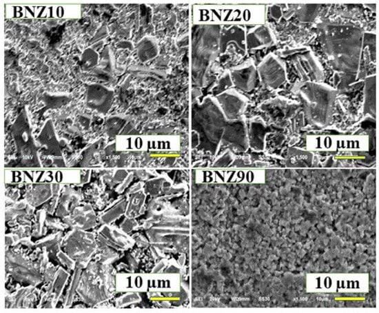
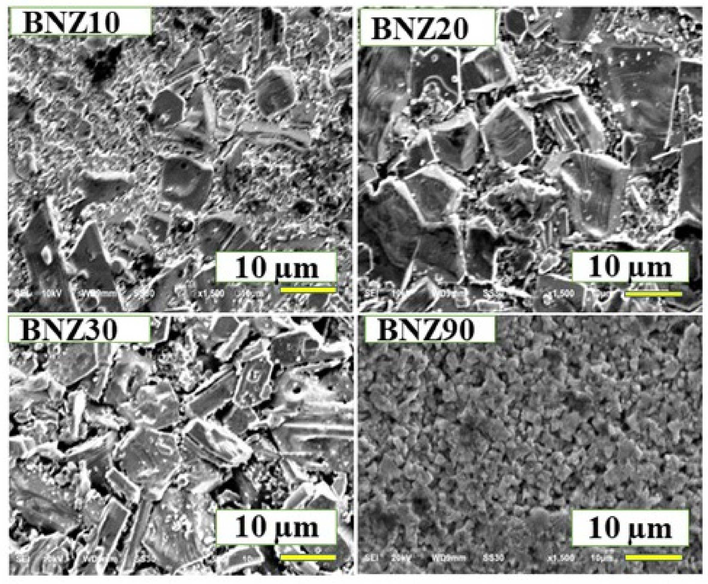
Representative SEM images for BNZx for x = 10, 20, 30, and 90 are shown in Figure 2. Images for other x-values are shown in the Supplementary Materials, Figure S3. Hexagonal crystallites of BaM are seen in the images for composites with low x-values. A gradual increase in hexagonal features with x is also evident for samples with 10 < x < 40. However, for 50 < x < 90, as the NZFO content increases, the hexagonal crystallites become small and less prominent, and larger grains likely belonging to NZFO appear in the SEM images. This behavior is consistent with our previous observations in composites of nickel ferrite and barium ferrite (BaM) [31].
Figure 2.
SEM images of BNZ10, BNZ20, BNZ30, and BNZ90 composites.
3.2. Magnetic Characterization
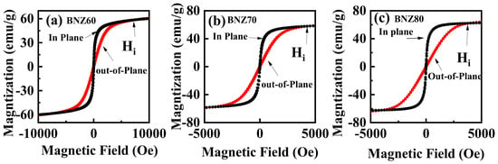
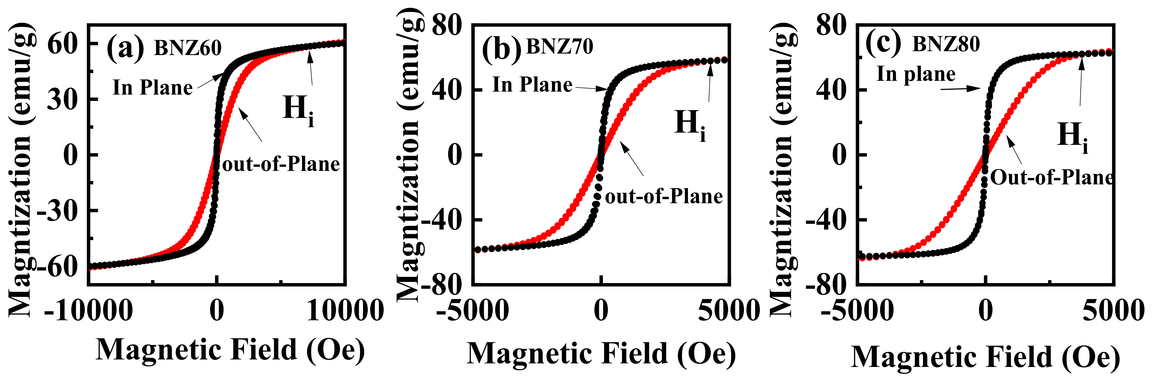
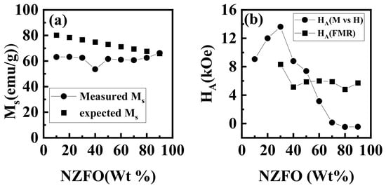
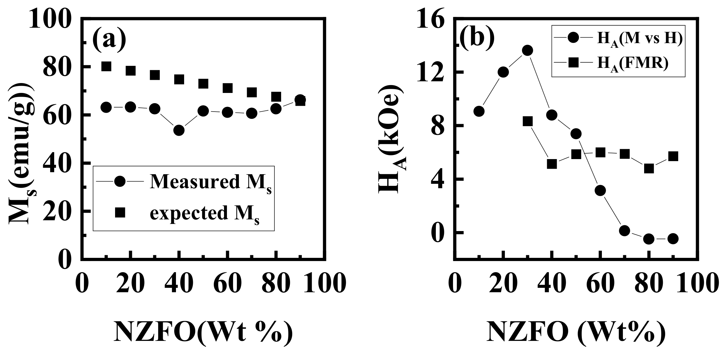
Magnetization (M) measurements as a function of H were done on BNZx composites for in-plane and out-of-plane fields. Representative M vs. H data for x = 60, 70, and 80 are shown in Figure 3 (Figure S4 in the Supplementary Materials shows M vs. H data for samples with other x-values). For in-plane H, the data in Figure 3 show a rapid increase in M to a saturation value Ms. For out-of-plane H, M attains saturation at a much higher value and is indicative of an in-plane crystalline anisotropy for all of the BNZx composites. Figure 4a shows Ms as a function of x, and one infers from Figure 4a that Ms increases with an increase in x for x ≥ 0.5. For comparison, we estimated the expected Ms values for BNZx from Ms for pure BaM and NZFO (from data in Figure S4). For Ms = 64 emu/g for NZFO and 82 emu/g for BaM, the expected Ms vs. x are plotted in Figure 4b, along with the measured values. The measured Ms are lower than the expected values and could be due to migration of Ni and nonmagnetic Zn from NZFO to BaM. Such diffusion of Zn and Ni could also account for the variation in the lattice constants of BaM in the composites [34] (Table 1).
Figure 3.
Magnetization M as a function of the applied field H for both in-plane and out-of-plane magnetic fields for (a) BNZ60, (b) BNZ70, and (c) BNZ80 composites.
Figure 4.
(a): Variations in the measured saturation magnetization Ms as a function of the weight percent x of NZFO in the composites. (b) Variation in the magnetocrystalline anisotropy HA with x in the BNZx composites. HA values determined from M vs. H data and from FMR are shown.
Figure 4b shows the anisotropy field HA estimated from the intersection field (Hi) corresponding to the overlap of the in-plane and out-of-plane M vs. H hysteresis loops. Analysis of the M vs. H data indicates that for lower x compositions, the positive values of HA suggest a predominant in-plane magnetic anisotropy. However, for higher x (BNZ80 and BNZ90), the observed negative HA indicates a transition toward out-of-plane anisotropy. A general decrease in HA with increasing x is evident from the data in Figure 4b. Since single-crystal M-type hexagonal ferrites have a uniaxial anisotropy field along the c-axis, the positive HA values imply that a significant fraction of crystallites of BaM in the polycrystalline composites with NZFO have an in-plane (a,b) orientation, whereas the negative HA at higher x suggests an increasing contribution of c-axis-oriented grains (out-of-plane alignment) in the polycrystalline BNZ composites.
3.3. Ferromagnetic Resonance
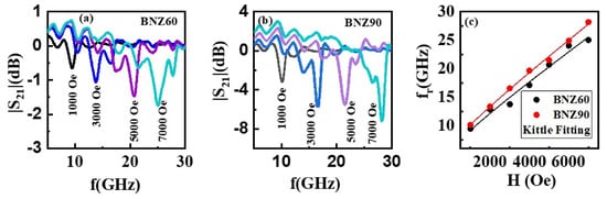
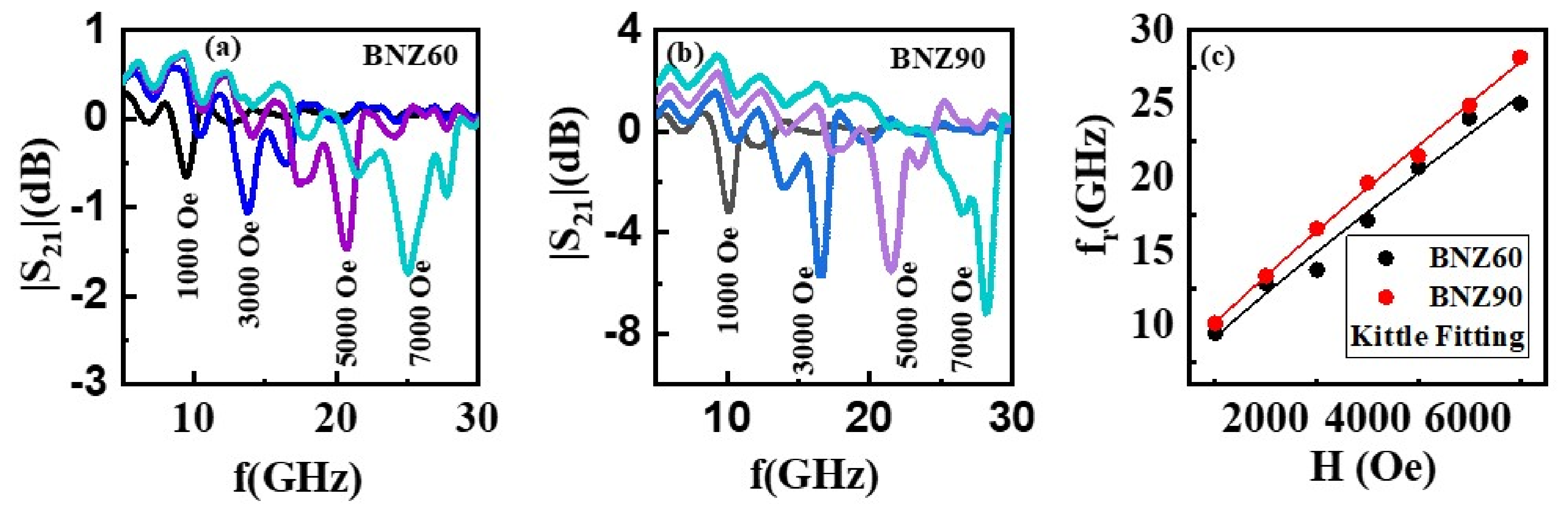
We also carried out FMR measurements on the rectangular platelets of the BNZx composites. The samples were placed in an S-shaped coplanar waveguide and excited with microwave power from a VNA. A static magnetic field H was applied parallel to the sample plane. Profiles of the scattering matrix S21 as a function of frequency f were recorded for a series of H-values. FMR originating from NZFO was observed in the frequency range of 5–30 GHz for composites with x ≥ 30. Resonances associated with magnetodielectric modes were observed in the 30–60 GHz frequency range and are not considered here for further analysis [35]. Representative profiles of S21 vs. f for BNZ60 and BNZ90 for in-plane H are plotted in Figure 5, and the dependence of the resonance frequency (fr) on H is shown in Figure 5c. FMR profiles for other x-values are shown in the Supplementary Materials, Figure S5.
Figure 5.
Profiles of scattering parameter S21 vs. f for (a) BNZ60 and (b) BNZ90 composites for in-plane static magnetic fields and (c) fitting of the FMR data on fr vs. H to the Kittel Equation (1).
One can fit the fr vs. H data to the Kittel equation given by
where g is the gyromagnetic ratio, H is the magnetic field in the x-direction, and Nx, Ny, and Nz are the demagnetization factors along the platelet’s length, width, and thickness, respectively. These demagnetization factor values for each composite are listed in Table S3 in the Supplementary Materials. The effective magnetization 4πMeff and the gyromagnetic ratio (g) were directly obtained from the fitting results. The anisotropy field HA was then calculated from 4πMeff and 4πM values at 5 kOe. The calculated HA values from FMR and M vs. H are plotted in Figure 4b (also listed in Table S4 in the Supplementary Materials). The FMR values of HA are smaller than the measured values from M vs. H data. The discrepancy in the two HA values could be due to an error in the demagnetization factors we used, assuming a near-ellipsoidal shape for our rectangular samples [36]. However, there is overall agreement in the trend in the variation in HA with x obtained from M vs. H and FMR. The most important inference from HA values is the high crystalline in-plane anisotropy field in the composites, which is a key ingredient for realizing ME coupling under zero external magnetic bias in a composite with a ferroelectric. The values of γ range from 2.5 MHz/Oe for BNZ30 to 2.7 MHz/Oe for BNZ90. These values are smaller than the 3 MHz/Oe reported for NZFO [23,37].
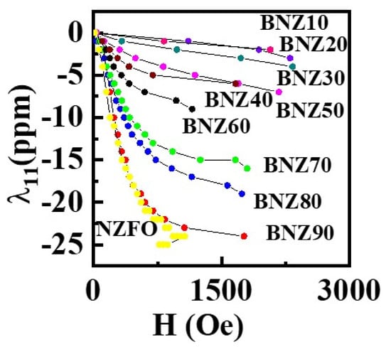
Magnetostriction of the ferromagnetic phase is a key parameter that determines the strength of ME coupling in the BNZx-PZT bilayers. We measured the variation in l with H in the platelets of BNZx using a strain gauge bonded to the sample surface. A strain indicator was used for the measurements of magnetostriction λ11 parallel to the sample length and to the applied magnetic field H. Figure 6 shows the λ11 vs. H data for BNZx samples and pure NZFO. All the samples show negative values, as expected [38]. With increasing NZFO content, λ11 gradually increases. For BNZ10, the highest value of λ11 is -2 ppm, comparable to the -1ppm for pure BaM [22,31]. For BNZ90, λ11 increases with H to −24 ppm, a value comparable to that of pure NZFO.
Figure 6.
Magnetostriction l11 vs. magnetic field H data measured parallel to the in-plane H for BNZx composites and pure NZFO.
3.4. Magnetoelectric Effects in the BNZx-PZT Bilayers
The BNZx platelets were bonded to vendor-supplied PZT with d33 = −400 pm/V, and their ME response was evaluated by measurements of the MEVC that depends on the piezomagnetic coupling coefficient q = dλ/dH and the piezoelectric coefficient d of PZT [1,39]. The H-dependence of MEVC was measured for two different field orientations: (i) α31 for H and the ac magnetic field h parallel (direction 1) to the sample length (direction 1), and V measured across the PZT thickness (direction 3); (ii) α33 for both H and h perpendicular to the bilayer plane, with V measured across the PZT thickness. The MEVC is given by MEVC = V/(h × t), where t is the thickness of the PZT.
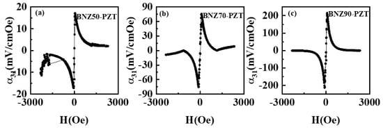
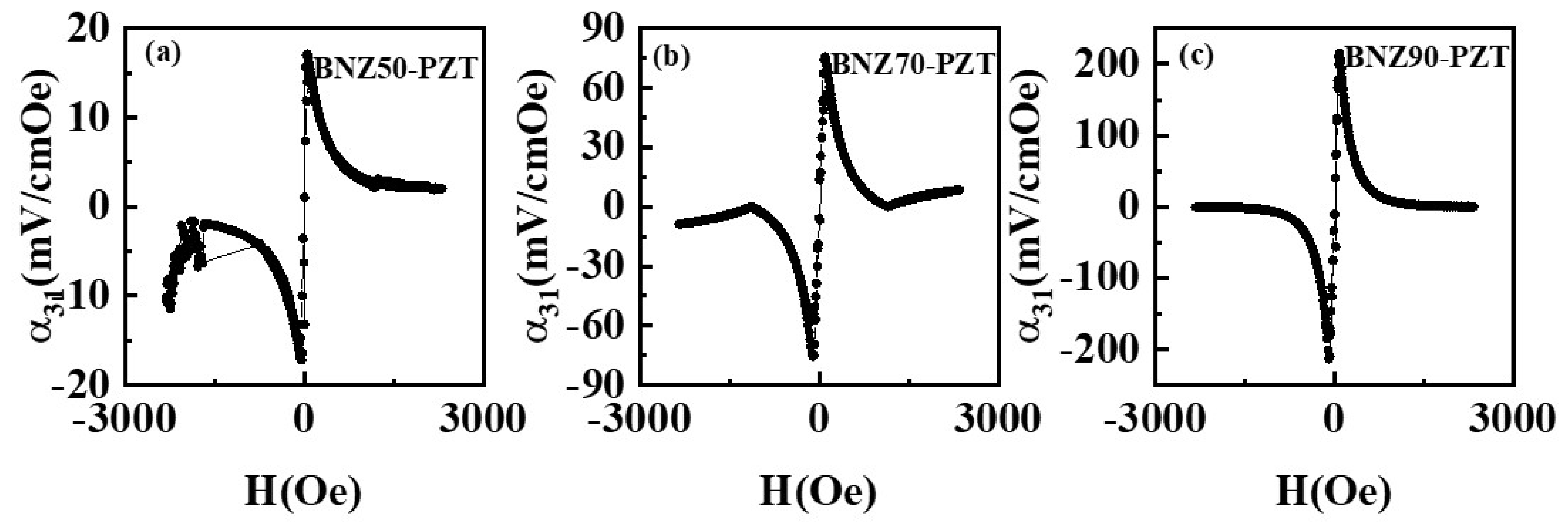
Figure 7 and the Supplementary Materials, Figure S6, show the H dependence of α31 for the ac field at 100 Hz. The ME response rises with increasing magnetic field, reaches a maximum, and then gradually decreases, and its magnitude essentially tracks the variation in q with H. When λ reaches near-saturation, the MEVC drops to very small values [1,39]. For low NZFO contents (x ≤ 40), the α31 vs. H shows a broad peak, and for x ≥ 50, the peak value of the MEVC increases as the Ni-Zn ferrite content increases. The maximum value of α31 increases from 3 mV/cm Oe for BNZ10-PZT to 161 mV/cm Oe for the BNZ90-PZT bilayer. This trend agrees well with the magnetostriction data, where the magnitude of λ11 increases with increasing NZFO content [39].
Figure 7.
α31 vs. H for the (a) BNZ50-PZT, (b) BNZ70-PZT, and (c) BNZ90-PZT bilayers.
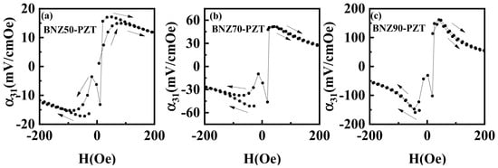
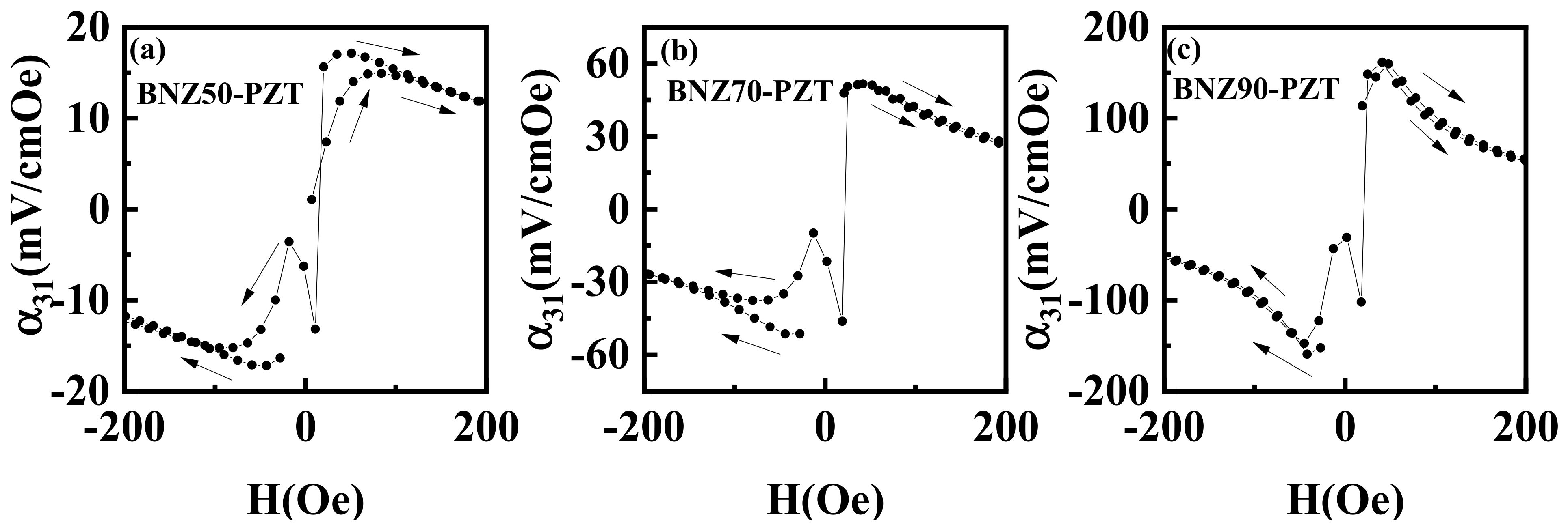
Figure 8 and Figure S7 in the Supplementary Materials show α31 vs. H around H = 0 on an expanded scale. A zero-bias ME response is observed in all bilayers, as expected, and α31 increases with NZFO content, from 1 mV/cm Oe for BNZ10-PZT to 114 mV/cm Oe for BNZ90-PZT. Hysteresis is observed in the H dependence of α31 for all bilayers. Upon reversal of the H direction, the magnitude of α31 initially decreases and then gradually increases with H to a maximum, after which it falls off rapidly at higher H values [1,39,40]. A weak secondary maximum in α31 near H = 0 is observed in Figure 8. This feature could be due to the dual-phase nature of the ferrite composite. The hard BaM and soft-magnetic NZFO phases exhibit different coercive fields, anisotropies, and magnetostrictive responses, leading to sequential magnetization reversal during field sweeping.
Figure 8.
Zero-bias region of α31 vs. H shown in expanded scale for (a) BNZ50-PZT, (b) BNZ70-PZT, and (c) BNZ90-PZT. The arrows represent the increasing and decreasing magnitude of H variation. The arrows indicate increasing or decreasing H values.
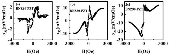
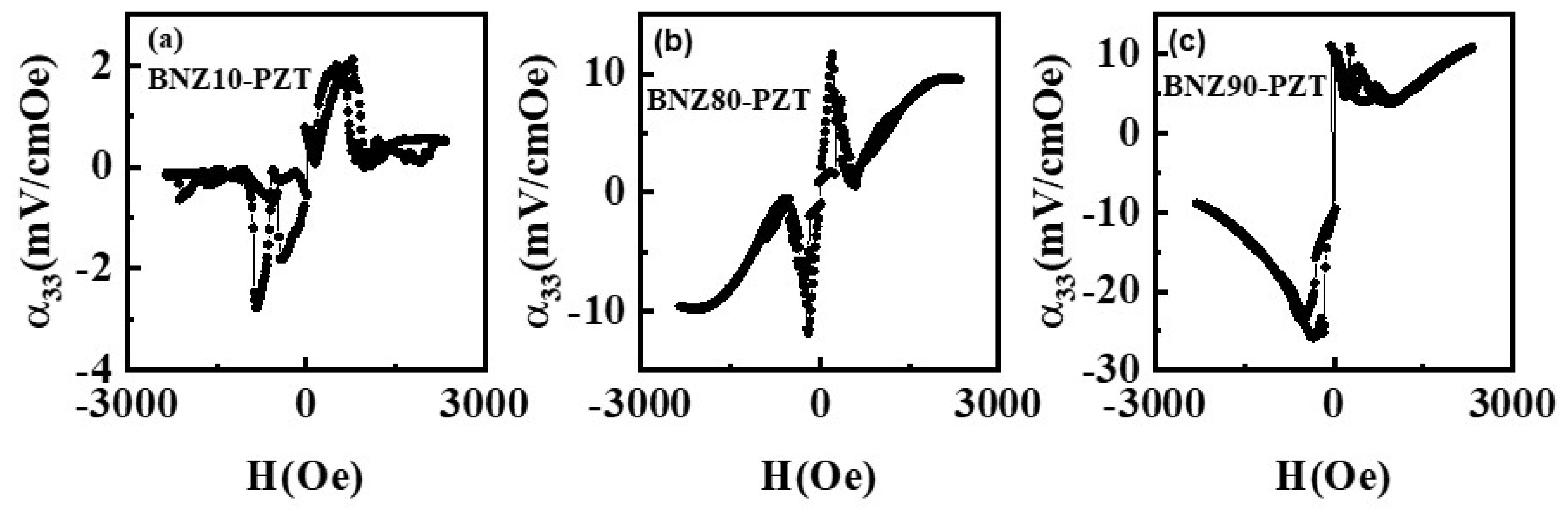
Figure 9 (and the Supplementary Materials, Figure S8) shows the H dependence of α33 for the ac field at 100 Hz, and α33 is much lower compared with α31 due to a large demagnetization factor for the out-of-plane DC and AC magnetic fields [41]. The magnitude of α33 increases with increasing NZFO content in the composites, from ~2 mV/cm Oe for BNZ10-PZT to 12 mV/cm Oe for the BNZ60-PZT bilayer. The small and nearly constant magnetostriction of BNZ10 makes the ME response weak.
Figure 9.
α33 vs. H for the (a) BNZ10-PZT, (b) BNZ80-PZT, and (c) BNZ90-PZT bilayers.
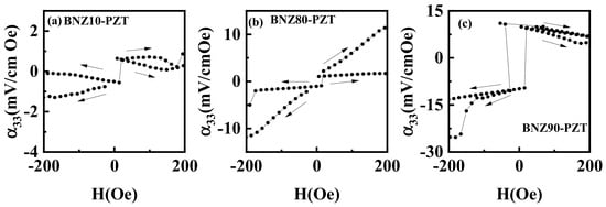
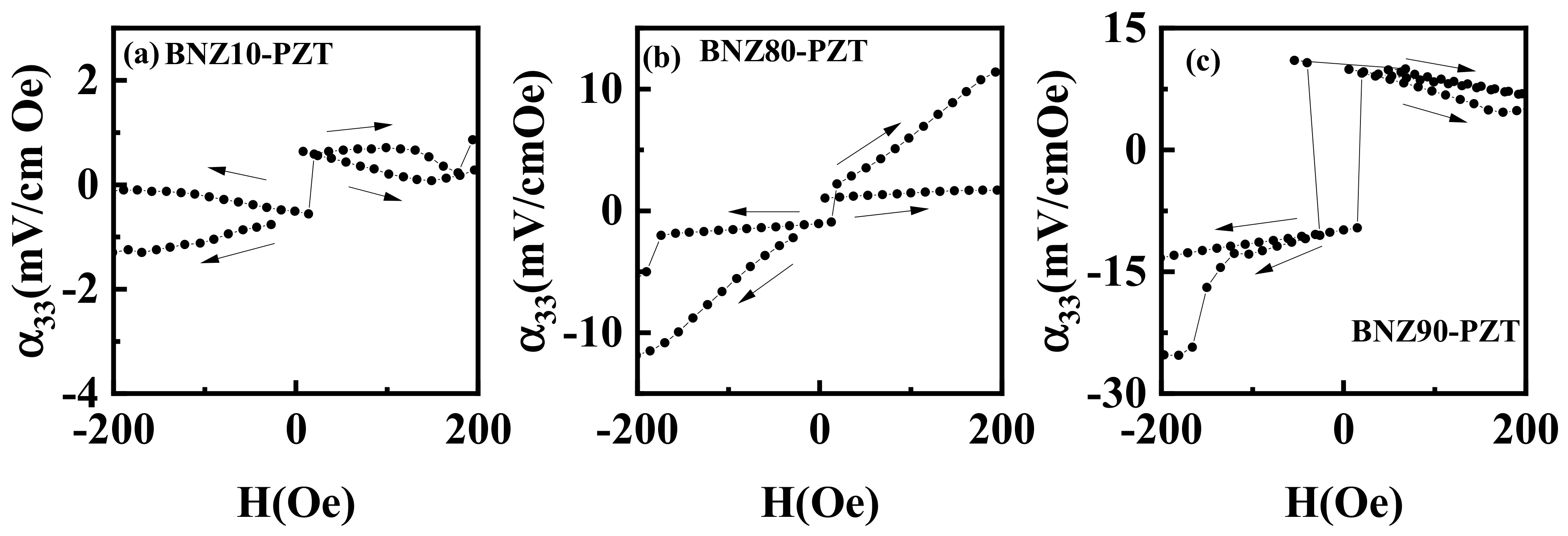
The zero-bias region of α33 vs. H is shown in Figure 10. A self-biased signal is still present, but it is weaker than in the longitudinal mode. The Supplementary Materials, Figure S9, show the same trend for the remaining compositions. Some intermediate compositions show sharper transitions near the zero field, which may be associated with stronger anisotropy-driven magnetic-switching behavior. However, these do not lead to a large ME voltage, indicating that anisotropy alone is not enough. A large anisotropy field helps create internal bias, but it does not contribute to ME response. Effective ME coupling requires a balance between anisotropy-induced bias and magnetostrictive strain transfer [17,39].
Figure 10.
Zero-bias region of α33 vs. H at expanded scale for (a) BNZ10-PZT, (b) BNZ80-PZT, and (c) BNZ90-PZT. The arrows represent the increasing and decreasing magnitude of H variation.
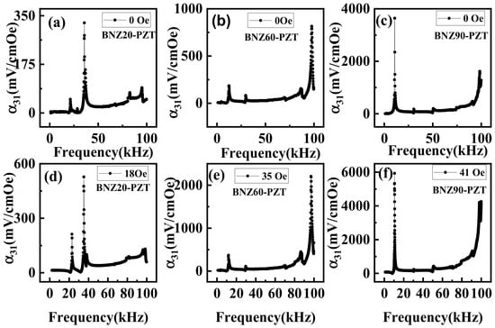
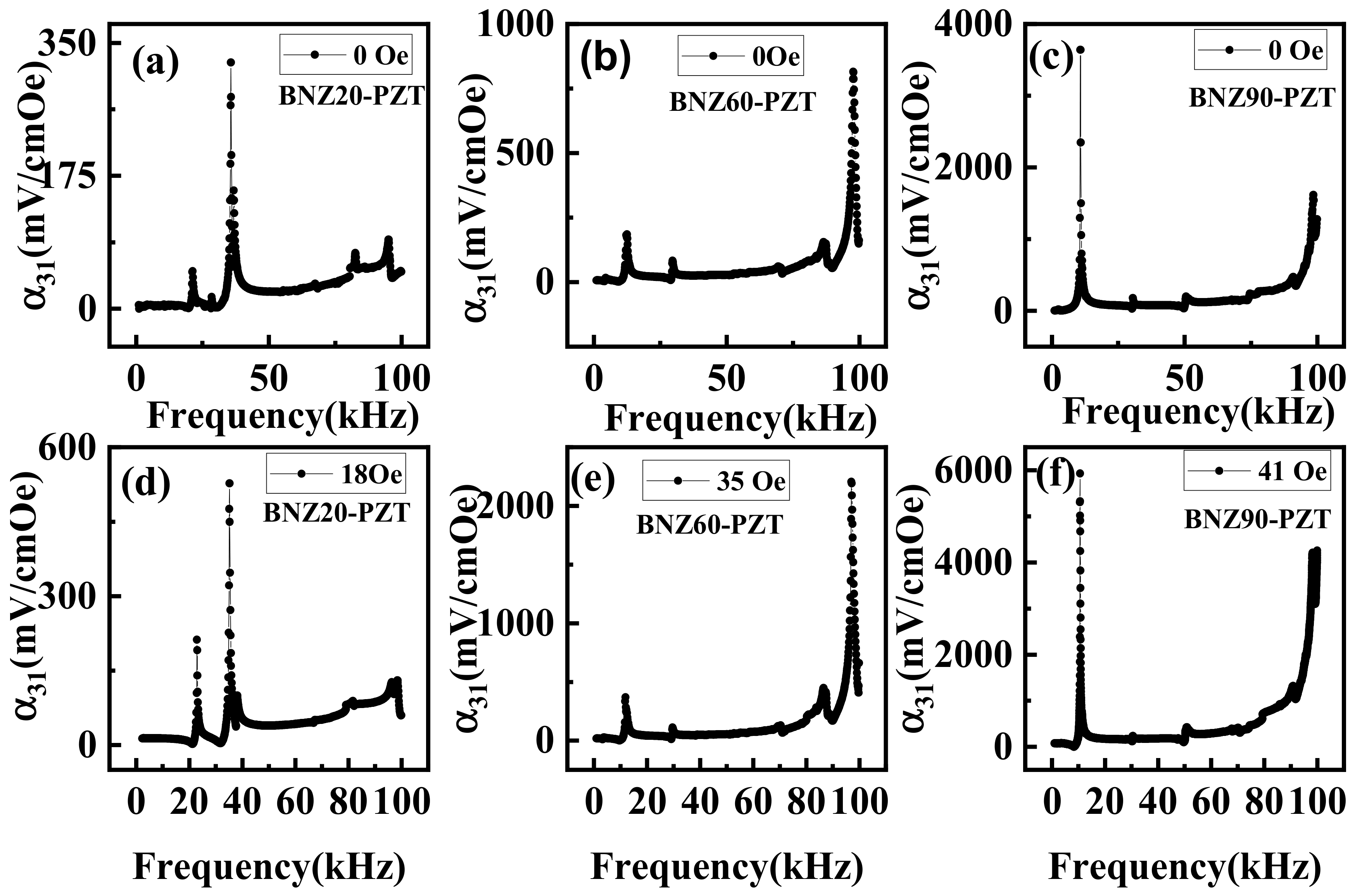
The frequency dependence of the MEVC was measured for BNZx-PZT bilayers. The results of the measurement of MEVC vs. f for BNZx-PZT (x = 20, 60, 90) are shown in Figure 11 and in the Supplementary Materials, Figure S10, for other x-values. Before these measurements, we obtained the resonance frequencies for the bending and longitudinal acoustic modes by measuring the frequency dependence of the impedance. The data were obtained for both zero bias and for H-values corresponding to the maximum of the low-frequency MEVC.
Figure 11.
Frequency dependence of ME coefficient α31 for BNZx–PZT bilayers. The results under self-bias (H = 0) are for (a) BNZ20-PZT, (b) BNZ60-PZT, and (c) BNZ90-PZT. The results with the application of a bias field corresponding maximum ME are for (d) BNZ20-PZT, (e) BNZ60-PZT, and (f) BNZ90-PZT.
The frequency-dependent ME response exhibits two distinct resonance peaks. The first (lower-frequency) peak corresponds to the bending (flexural) resonance mode, whereas the second (higher-frequency) peak corresponds to the longitudinal acoustic resonance mode. The resonance modes were identified from impedance measurements and are consistent with the resonance behavior reported for magnetoelectric composites [1,4]. For BNZx-PZT bilayers with x = 20, 40, 50, 80, and 90, the first resonance (bending mode) produces the larger MEVC, which can be attributed to enhanced flexural deformation leading to amplified strain in the piezoelectric layer, particularly away from the neutral axis, as discussed in Ref. [4]. In contrast, for BNZx (x = 10, 30, 60, 70) samples, the second resonance corresponding to the longitudinal acoustic mode exhibits a higher MEVC, indicating that axial strain transfer is more efficient in these compositions. This variation in the dominant resonance mode indicates that the interplay between bending and longitudinal vibrations is governed by changes in magnetostriction, elastic stiffness, and magnetic anisotropy with BNZx content, which determine the efficiency of strain transfer across the bilayer.
Among the BNZx-PZT bilayers, the highest MEVC of 6V/cm Oe is measured at the bending resonance frequency of 10.6 kHz for BNZ90-PZT at H = 41 Oe, and the corresponding zero-bias MEVC = 3.6V/cm.Oe. For lower x-values, x = 10–50, the MEVC values exhibit relatively low values at resonance, less than 1 V/cm Oe, suggesting weaker magnetoelectric coupling. This could be attributed to lower piezoelectric activity at these concentrations. The MEVC values increase significantly with increasing Ni-Zn composition for x = 60–90 due to a strong magnetostrictive response in the ferromagnetic phase. Overall, the results in Figure 7, Figure 8, Figure 9, Figure 10 and Figure 11 and in the Supplementary Materials, Figures S6–S10, show a clear enhancement in the strengths of ME coupling as the amount of NZFO is increased.
4. Discussion
The experimental results demonstrate that phase-pure composites combining spinel and M-type hexagonal ferrites can be synthesized without detrimental secondary phases, ultimately yielding a strong zero-bias ME response when coupled with PZT. The signature XRD peaks for both constituent phases—NZFO and BaM—confirm that the structural integrity of each phase is preserved during sintering. Retaining the phase purity of the highly anisotropic BaM ensures the development of a strong internal magnetocrystalline anisotropy field, while the unreacted NZFO phase provides the necessary magnetoelastic compliance. This structural distribution is supported by the SEM surface morphology, which reveals distinct hexagonal BaM grains that naturally become more prominent as the NZFO weight fraction decreases.
As expected, the NZFO-rich composites (x > 60) exhibit high magnetostriction levels approaching those of pure zinc-substituted nickel ferrite, whereas the BaM-rich sample (BNZ10) displays poor magnetostrictive strain. To evaluate how these mixed phases influence the overall magnetic behavior, the magnetic anisotropy was evaluated using both FMR data and macroscopic M vs. H loops. The internal anisotropy field HA derived from FMR yielded consistently higher values for the NZFO-rich samples (x = 60, 70, 80, 90) compared with the values extracted via static M vs. H. These fields operate in-plane, suggesting a preferential alignment of the BaM grains within the (a,b) crystallographic planes. Concurrently, HA from the intersection of the in-plane and out-of-plane magnetization curves (HA = Hi − 4πMs) steadily decreases with increasing NZFO content. For the BaM-rich compositions, the positive HA values confirm an in-plane easy axis alignment. However, as the soft NZFO phase begins to dominate, this internal field drops, ultimately flipping to small, negative values for BNZ80 and BNZ90. This negative sign signifies a clear transition toward an out-of-plane easy axis orientation. While highly textured BaM films typically display a strong out-of-plane anisotropy depending on grain orientation [42], the bulk BNZ composites studied here show a predominant in-plane anisotropy for x < 70 (peaking near BNZ30) before shifting to an out-of-plane character at high spinel concentrations (x = 80, 90). The discrepancy between HA values estimated from FMR and M vs. H might be due to sample response under high-frequency and static magnetic measurements.
The microstructural configuration directly controls the self-biasing performance. By maintaining separate micro-scale domains rather than an exchange-coupled nanoscale network, the high magnetocrystalline anisotropy field of the hard BaM phase is preserved. The internal remanent magnetic flux from these hexaferrite grains provides the necessary localized magnetic bias for the soft NZFO. The spinel grains retain their distinct phase boundaries and undergo magnetoelastic deformation without being mechanically clamped by a rigid BaM and maintain high bulk magnetostriction levels (~−24 ppm at x = 90). The performance of the bilayer relies on effective strain transfer across two distinct interfaces: the internal microscale boundaries between the BaM and NZFO grains, and the macroscopic bonding layer between the composite and the PZT plate. High sintering density prevents mechanical loss within the composite matrix. The magnetostrictive strain generated by the soft NZFO grains is transferred through the bonding medium to the PZT layer, maximizing the induced piezoelectric voltage.
While ferrite–PZT bilayers are widely documented, this configuration differs from conventional designs by utilizing a compositionally engineered magnetic layer that systematically balances a hard hexaferrite with a soft, highly magnetostrictive spinel ferrite. Rather than substituting one ferrite phase entirely, varying the BaM/NZFO weight ratio serves as a mechanism to balance internal anisotropy against macro-magnetostriction, optimizing both the internal magnetic bias and the resulting strain-mediated ME coupling. This approach bypasses the need for an external DC bias field. Furthermore, the selection of a zinc-substituted spinel ferrite provides a noticeable performance advantage over previously studied BaM-NiFe2O4 configurations [31].
Using a self-biased magnetic phase containing both hexagonal and spinel structures clearly provides a viable pathway to strong zero-bias ME behavior. Previous studies on Zn-substituted spinel ferrite–PZT multilayers reported low-frequency ME voltage coefficients of 280 mV/cm Oe for cobalt–zinc ferrite–PZT and 600 mV/cm Oe for NZFO-PZT under an applied magnetic field [43,44]. Although these systems exhibit larger MEVCs than BNZx-PZT, their MEVCs under zero bias were essentially zero. In contrast, incorporating BaM with high magnetocrystalline anisotropy into the NZFO-PZT bilayers introduces an internal magnetic bias that enables substantial ME coupling without an external dc magnetic field. In our previous study on BaM/NiFe2O4–PZT bilayers, the maximum values of a31 under zero bias were 22 mV/cm Oe and 0.9 V/cm Oe for low frequency and at EMR, respectively [31]. In comparison, in the present system, the corresponding zero-bias values are a31 = 113 mV/cm Oe and 3.6 V/cm Oe. Thus, the enhancement in l due to Zn substitution in nickel ferrite resulted in a substantial strengthening of ME coupling across both low-frequency and resonance regimes, outperforming previous values for hexaferrite-based ME composites [16,31]. This confirms that Zn substitution acts as a primary driver for increasing magnetostrictive strain while allowing the composite to retain enough collective internal anisotropy for self-biased operation, a result of the enhanced magnetoelastic compliance of the modified spinel phase [5,44]. Ultimately, these results underscore the role of compositional tuning in the BNZ layer for tailoring the magnetic and ME properties of the bilayer system. Interlocking the high l of the Ni-Zn ferrite with the permanent internal flux of the BaM phase yields a composite system capable of high sensitivity under zero-bias conditions. This combination makes these BNZx-PZT bilayers highly practical options for compact magnetic field sensors and stress-mediated energy-harvesting systems [45].
Although magnetoelectric bilayers based on ferrite–PZT have been extensively investigated, the present work differs from previous studies by employing a compositionally engineered magnetic layer consisting of both a hard M-type hexaferrite (BaM) and a highly magnetostrictive Ni-Zn spinel ferrite (NZFO). Rather than simply replacing one ferrite with another, the BaM/NZFO ratio was systematically varied to tailor the balance between magnetocrystalline anisotropy and magnetostriction, thereby optimizing the internal magnetic bias and magnetoelectric coupling. This compositional engineering enables strong self-biased magnetoelectric behavior without the use of externally applied DC magnetic bias and demonstrates that Zn substitution in the spinel ferrite is an effective route for significantly improving the magnetoelectric performance compared with previously reported BaM-NiFe2O4 composites.
A model for ME coupling under self-magnetic bias in a composite is lacking at present. There are well-developed models that relate the magnetostriction and piezomagnetic coefficient of the ferromagnetic phase and the piezoelectric order parameters to the MEVC at low frequency and at resonance modes. The magnetoelectric response in strain-mediated layered structures can be modeled using an analytical constitutive approach based on the piezomagnetic and piezoelectric field equations [1,2,5]. The low-frequency magnetoelectric voltage coefficient (α31) can be explicitly linked to parameters via structural and material parameters. Models that relate the magnetic anisotropy to the MEVC, however, are yet to be developed, since several mechanisms could result in ME response under a self-magnetic bias generated by grading the magnetization, insertion of a high-permeability layer in the composite, laser annealing of the magnetic layer, etc. [9,10,11,12,13,14,15].
Finally, we compare the ME coupling strength under self-bias in BNZx/PZT with reported values in self-biased composites [9,10,11,12,13,14,15]. Several avenues were pursued in the past to achieve a self-magnetic bias in composites, including (i) functionally graded magnetic structures by variation in the chemical composition, magnetization, or magnetostriction to create an internal magnetic field; (ii) exchange-bias structures in which coupling between magnetically hard and soft phases shifts the magnetic and magnetostriction loops, leaving a nonzero response at zero applied bias; (iii) magnetostriction hysteresis in materials such as Ni or SmFe2, yielding nonzero strain sensitivity at zero field; and (iv) residual stress from co-firing, thermal expansion mismatch, lattice mismatch, or thin-film growth that alters magnetic anisotropy and strain transfer, enabling or enhancing self-bias. To compare low-frequency and resonant ME coefficients across self-bias schemes, the representative results show clear trends [9]. In exchange-bias laminates, Metglas/PZT/Metglas exhibits α ≈ 12 V/cm Oe at 1 kHz (zero bias) and rises to α ≈ 380 V/cm Oe at 33.7 kHz (EMR), whereas the exchange-biased multilayer on AlN reaches α ≈ 96.7 V/cm Oe at 1.19 kHz at zero bias. For magnetostriction hysteresis systems, a Ni/MFC laminate yields α ≈ 1.25 V/cm Oe at 1 kHz (zero bias). Built-in stress in co-fired ceramics of nickel–cobalt ferrite and PMN-PT provides α ≈ 1.21 V/cm Oe at 1 kHz. Functionally graded Ni-Metglas ferromagnetic laminates and PZT achieve α ≈ 89.2 V/cm Oe. The above values are much higher than the ME coupling strength reported here due to the use of transition metals or alloys for the ferromagnetic phase [9,10,11,12,13,14,15]. While composition and microscale tuning serve as effective parameters for altering internal fields, recent developments have demonstrated that spatially engineered architectures and complex structural designs, rather than uniform compositional adjustments alone, provide highly alternative pathways for optimizing mechanical and multiferroic couplings across interactive matrices [46].
5. Conclusions
In summary, dual-phase ferromagnetic composites comprising M-type barium hexaferrite, BaM, and nickel–zinc spinel ferrite (NZFO) were successfully synthesized via conventional solid-state reaction and integrated with PZT to form bilayer structures. The primary goal was to achieve strong ME coupling without the need for an external DC bias field. Ferromagnetic resonance and a law-of-approach analysis of the in-plane and out-of-plane M vs. H hysteresis loops confirmed that the composites maintain strong macroscopic magnetocrystalline anisotropy, as evidenced by the high anisotropy field resolved in the BNZ30 sample.
ME voltage coefficient measurements revealed a strong compositional dependence. The BNZ90-PZT bilayer (rich in NZFO) exhibited the highest overall performance, yielding a low-frequency MEVC of 161.5 mV/cm Oe and a peak value of 6 V/cm Oe at the electromechanical resonance frequency of 10.6 kHz under a residual bias field of ~40 Oe. Crucially, this same composition demonstrated strong zero-bias values of 114 mV/cm Oe at 100 HZ and 3.6 V/cm Oe at resonance. In contrast, the lowest performance was observed for the BNZ10-PZT bilayer, which registered just 3.3 mV/cm Oe at 100 Hz. These findings show that compositional tuning of the magnetic phase is a viable path for optimizing self-biased ME composites. Balancing the internal field of hard ferrites with the magnetoelastic compliance of soft ferrites allows for strong zero-bias cross-coupling without external biasing elements. Consequently, these BNZx-PZT bilayers, particularly those with higher spinel contents, hold distinct potential for compact magnetic sensors, tunable microwave devices, and energy-harvesting technologies.
Supplementary Materials
The following supporting information can be downloaded at https://www.mdpi.com/article/10.3390/ceramics9110120/s1. Figure S1 shows the X-ray diffraction (XRD) patterns for magnetic composites with (100 − x) wt.% barium hexaferrite (BaM) and x wt.% nickel–zinc ferrite (NZFO) for a series of x-values. The indexed reflections correspond to the hexagonal BaM and cubic spinel NZFO phases. Table S1: The NZFO and BaM contents of the BNZ composites estimated from X-ray diffraction data in Figure 1 and Figure S1. Figure S2: X-ray diffraction (XRD) patterns for platelets of the BNZx composites with (100 − x) wt.% barium hexaferrite (BaM) and x wt.% nickel–zinc ferrite (NZFO) for a series of x-values. The patterns for 2q = 20–65 deg were obtained specifically to verify the phase purity of the composites, since the presence of an impurity phase, BaFe2O4, will have the most intense diffraction peaks in the 20 to 30 deg. region. The data indicate the absence or too small an amount of the impurity that cannot be detected by XRD. Table S2: Chemical compositions of BaM and NZFO in BNZx composites determined by EDS/EDAX. The results are for different SEM magnifications and surface spots on the composite platelets. Figure S3 shows the SEM images of BNZx (x = 40, 50, 60, 70, and 80). Figure S4: Magnetization vs. magnetic field data for BNZx (x = 10, 20, 30, 40, 50, and 90) composites. M vs. H data of pure BaM (BNZ0) and pure NZFO (BNZ100) are also shown at the bottom. Figure S5: S21 vs. f profiles showing FMR modes in BNZx composites at selected bias magnetic fields. Ferromagnetic resonance frequency of BNZx (x = 30, 40, 50, 70, and 80) composites is plotted as a function of external magnetic field (H). Table S3: Demagnetization factors for BNZ composites. Table S4: Fitting parameters for FMR and magnetic parameters for BNZx composites. Figure S6: Transverse MEVC (α31) as a function of magnetic field (H) for BNZx-PZT bilayers (x = 10, 20, 30, 40, 60, and 80) for in-plane magnetic fields. Figure S7: Enlarged region of MEVC (α31) vs. H for BNZx-PZT bilayers (x = 10, 20, 30, 40, 60, and 80). Figure S8: Longitudinal MEVC (α33) as a function of magnetic field (H) for BNZx-PZT bilayers (x = 20, 30, 40, 50, 60, and 70) for out-of-plane magnetic fields. Figure S9: Enlarged region of MEVC (α33) vs. H for BNZx-PZT bilayers (x = 20, 30, 40, 50, 60, and 70). Figure S10: Frequency dependence of MEVC (α31) for BNZx (x = 10, 30, 40, 50, 70, and 80) PZT bilayers at selected zero-biased field and maximum field.
Author Contributions
All authors contributed to this work. S.A., S.S., R.B. and S.B. were involved in sample synthesis. S.A., S.S., R.M., M.J., M.R.P. and G.S. performed data curation and formal analysis. S.A. and G.S. prepared this manuscript. M.J., M.R.P. and G.S. acquired the funding. All authors have read and agreed to the published version of the manuscript.
Funding
The research at Oakland University was supported by grants from the National Science Foundation (NSF) (ECCS-2415328; ECCS-EAGER-2236879) and the Air Force Research Laboratory (AFRL—Award No. FA9550-23RXCOR001). The research at the AFRL was supported by a grant from the Air Force Office of Scientific Research (Award No. FA9550-23RXCOR001). Efforts at the University of Connecticut were supported by a grant from the NSF (ECCS-EAGER-2236879).
Data Availability Statement
The raw data supporting the conclusions of this article will be made available by the authors on request.
Acknowledgments
During the preparation of the graphical abstract, the authors used GPT-4o Mini for guidance on the layout and organization. The authors have reviewed and edited the output and take full responsibility for the content of this publication.
Conflicts of Interest
The authors declare no conflicts of interest.
References
- Nan, C.-W.; Bichurin, M.I.; Dong, S.; Viehland, D.; Srinivasan, G. Multiferroic magnetoelectric composites: Historical perspective, status, and future directions. J. Appl. Phys. 2008, 103, 031101. [Google Scholar] [CrossRef] [Scilit]
- Sun, N.; Priya, S.; Srinivasan, G. (Eds.) Composite Magnetoelectrics: Materials, Structures, and Applications; Elsevier: Amsterdam, The Netherlands, 2015. [Google Scholar]
- Patil, D.R.; Chu, Z.; Dong, S.; Kim, K.H.; Song, H.; Jeong, D.-Y.; Ryu, J. Progress, challenges, and perspectives of magnetoelectric composites and devices based on relaxor-PT single crystals. Appl. Phys. Rev. 2025, 12, 011302. [Google Scholar] [CrossRef] [Scilit]
- Dong, S.; Li, J.F.; Viehland, D. Giant magnetoelectric effect in laminate composites. Philos. Mag. Lett. 2003, 83, 769–773. [Google Scholar] [CrossRef] [Scilit]
- Zhai, J.; Xing, Z.; Dong, S.; Li, J.; Viehland, D. Magnetoelectric laminate composites: An overview. J. Am. Ceram. Soc. 2008, 91, 351–358. [Google Scholar] [CrossRef] [Scilit]
- Hu, J.-M.; Chen, L.-Q.; Nan, C.-W. Multiferroic heterostructures integrating ferroelectric and magnetic materials. Adv. Mater. 2016, 28, 15–39. [Google Scholar] [CrossRef] [Scilit] [PubMed]
- Gupta, R.; Kotnala, R.K. A review on current status and mechanisms of room-temperature magnetoelectric coupling in multiferroics for device applications. J. Mater. Sci. 2022, 57, 12710–12737. [Google Scholar] [CrossRef] [Scilit]
- Vopson, M.M. Fundamentals of multiferroic materials and their possible applications. Crit. Rev. Solid State Mater. Sci. 2015, 40, 223–250. [Google Scholar] [CrossRef] [Scilit]
- Zhou, Y.; Maurya, D.; Yan, Y.; Srinivasan, G.; Quandt, E.; Priya, S. Self-biased magnetoelectric composites: An overview and future perspectives. Energy Harvest. Syst. 2016, 3, 1–42. [Google Scholar] [CrossRef]
- Mantese, J.V.; Micheli, A.L.; Schubring, N.W.; Hayes, R.W.; Srinivasan, G.; Alpay, S.P. Magnetization-graded ferromagnets: The magnetic analogs of semiconductor junction elements. Appl. Phys. Lett. 2005, 87, 082503. [Google Scholar] [CrossRef] [Scilit]
- Mandal, S.K.; Sreenivasulu, G.; Petrov, V.M.; Srinivasan, G. Magnetization-graded multiferroic composite and magnetoelectric effects at zero bias. Phys. Rev. B 2011, 84, 014432. [Google Scholar] [CrossRef] [Scilit]
- Liu, S.; Liao, S.; Wei, K.; Deng, L.; Zhao, L.; Zou, H. Self-biased magnetoelectric composite for energy harvesting. Battery Energy 2023, 2, 20230005. [Google Scholar] [CrossRef] [Scilit]
- Zhang, J.; Du, H.; Xia, X.; Fang, C.; Weng, G.J. Theoretical study on self-biased magnetoelectric effect of layered magnetoelectric composites. Mech. Mater. 2020, 151, 103609. [Google Scholar] [CrossRef] [Scilit]
- Annapureddy, V.; Park, S.H.; Song, H.; Ryu, J. Tunable self-biased magnetoelectric effect in magnetization-graded magnetoelectric composites. J. Alloys Compd. 2023, 957, 170121. [Google Scholar] [CrossRef] [Scilit]
- Xian, D.; Zhao, Y.; Du, Y.; Xu, Y.; Qiao, J.; Wu, J.; Lin, Q.; Liu, M.; Jiang, Z. Highly magneto-electric-mechanical coupling effect in self-biased magnetoelectric composite induced by laser thermal annealing. Microsyst. Nanoeng. 2025, 11, 142. [Google Scholar] [CrossRef] [Scilit] [PubMed]
- Pan, Q.; Zhang, X.; Xia, B.; Chu, B. Magnetoelectric response in laminated BaFe12O19/Pb(Zr,Ti)O3 composites. J. Appl. Phys. 2023, 133, 244101. [Google Scholar] [CrossRef] [Scilit]
- Pullar, R.C. Hexagonal ferrites: A review of the synthesis, properties and applications of hexaferrite ceramics. Prog. Mater. Sci. 2012, 57, 1191–1334. [Google Scholar] [CrossRef] [Scilit]
- Mitsuda, H.; Mori, S.; Okazaki, C. The crystal structure of barium monoferrite, BaFe2O4. Acta Crystallogr. B 1971, 27, 1263–1269. [Google Scholar] [CrossRef] [Scilit]
- Nergis, B.; Bauer, S.; Jin, X.; Seemann, K.; Horak, L.; Schneider, R.; Holy, V.; Ulrich, S.; Baumbach, T. Effect of the laser fluence on the microstructure and the relating magnetic properties of BaFe12O19 films grown on YSZ (111) by PLD for optimized perpendicular recording. J. Mater. Sci. 2023, 58, 718–739. [Google Scholar] [CrossRef] [Scilit]
- Pankhurst, Q.A. Anisotropy field measurement in barium ferrite powders by applied field Mössbauer spectroscopy. J. Phys. Condens. Matter 1991, 3, 1323. [Google Scholar] [CrossRef] [Scilit]
- Topal, U. Factors influencing the remanent properties of hard magnetic barium ferrites: Impurity phases and grain sizes. J. Magn. Magn. Mater. 2008, 320, 331–335. [Google Scholar] [CrossRef] [Scilit]
- Fonton, S.S.; Zalesskii, A.V. Magnetostriction of a single crystal of hexagonal ferrite BaFe18027. Sov. Phys. JETP 1965, 20, 1138. [Google Scholar]
- Özgür, Ü.; Alivov, Y.; Morkoç, H. Microwave ferrites, part 1: Fundamental properties. J. Mater. Sci. Mater. Electron. 2009, 20, 789–834. [Google Scholar] [CrossRef] [Scilit]
- Kaur, A.; Sharma, P.; Bhardwaj, S.; Kumar, M.; Sharma, I.; Batoo, K.M.; Kumar, G. A review on synthesis and characterizations of mixed nickel-zinc ferrites. In Ferrite-Nanostructures with Tunable Properties and Diverse Applications; Springer: Berlin/Heidelberg, Germany, 2021; pp. 189–217. [Google Scholar]
- Vinnik, D.A.; Zhivulin, V.E.; Sherstyuk, D.P.; Starikov, A.Y.; Zezyulina, P.A.; Gudkova, S.A.; Zherebtsov, D.A.; Rozanov, K.N.; Trukhanov, S.V.; Astapovich, K.A.; et al. Ni substitution effect on the structure, magnetization, resistivity and permeability of zinc ferrites. J. Mater. Chem. C 2021, 9, 5425–5436. [Google Scholar] [CrossRef] [Scilit]
- Nikmanesh, H.; Moradi, M.; Kameli, P.; Bordbar, G.H. Effects of annealing temperature on exchange spring behavior of barium hexaferrite/nickel zinc ferrite nanocomposites. J. Electron. Mater. 2017, 46, 5933–5941. [Google Scholar] [CrossRef] [Scilit]
- Remya, K.P.; Prabhu, D.; Amirthapandian, S.; Viswanathan, C.; Ponpandian, N. Exchange spring magnetic behavior in BaFe12O19/Fe3O4 nanocomposites. J. Magn. Magn. Mater. 2016, 406, 233–238. [Google Scholar] [CrossRef] [Scilit]
- Petrecca, M.; Muzzi, B.; Oliveri, S.M.; Albino, M.; Yaacoub, N.; Peddis, D.; Fernández, C.d.J.; Innocenti, C.; Sangregorio, C. Optimizing the magnetic properties of hard and soft materials for producing exchange spring permanent magnets. J. Phys. D Appl. Phys. 2021, 54, 134003. [Google Scholar] [CrossRef] [Scilit]
- Huang, D.; Wen, X.; Dai, J.; Wang, Q.; Liu, H.; Li, Z. Magnetic properties and exchange coupling effects of SrFe12O19@MFe2O4 (M = Co, Ni, Zn) as hard-soft magnetic ferrite core–shell nanofibers. J. Supercond. Nov. Magn. 2023, 36, 711–719. [Google Scholar] [CrossRef] [Scilit]
- Singh, H.K.; Mohapatra, P.P.; Pandey, S.; Dobbidi, P. Unlocking the potential of hexaferrite–spinel ferrite composites: Microstructure-induced colossal permittivity and relaxation phenomena. J. Appl. Phys. 2023, 134, 194103. [Google Scholar] [CrossRef] [Scilit]
- Saha, S.; Acharya, S.; Popov, M.; Sauyet, T.; Pfund, J.; Bidthanapally, R.; Jain, M.; Page, M.R.; Srinivasan, G. A novel spinel ferrite–hexagonal ferrite composite for enhanced magnetoelectric coupling in a bilayer with PZT. Sensors 2023, 23, 9815. [Google Scholar] [CrossRef] [Scilit] [PubMed]
- Narang, S.B.; Pubby, K. Nickel spinel ferrites: A review. J. Magn. Magn. Mater. 2021, 519, 167163. [Google Scholar] [CrossRef] [Scilit]
- Hoëz, A.; Mattei, J.-L.; Chevalier, A. New manufacturing process for granular texture management in polycrystalline BaM hexaferrites through the goethite crystallite laths aspect ratio, and a specialized law of approach to the magnetic saturation for partly polarized uniaxial materials. Magnetochemistry 2023, 9, 30. [Google Scholar] [CrossRef] [Scilit]
- Behera, P.; Ravi, S. Effect of Ni doping on structural, magnetic and dielectric properties of M-type barium hexaferrite. Solid State Sci. 2019, 89, 139–149. [Google Scholar] [CrossRef] [Scilit]
- Sheen, J. Comparisons of microwave dielectric property measurements by transmission/reflection techniques and resonance techniques. Meas. Sci. Technol. 2009, 20, 042001. [Google Scholar] [CrossRef] [Scilit]
- Joseph, R.I.; Schlömann, E. Demagnetizing field in nonellipsoidal bodies. J. Appl. Phys. 1965, 36, 1579–1593. [Google Scholar] [CrossRef] [Scilit]
- Thakur, P.; Taneja, S.; Chahar, D.; Ravelo, B.; Thakur, A. Recent advances on synthesis, characterization and high frequency applications of Ni-Zn ferrite nanoparticles. J. Magn. Magn. Mater. 2021, 530, 167925. [Google Scholar] [CrossRef] [Scilit]
- Licci, F.; Rinaldi, S. Magnetostriction of some hexagonal ferrites. J. Appl. Phys. 1981, 52, 2442–2443. [Google Scholar] [CrossRef] [Scilit]
- Ma, J.; Hu, J.; Li, Z.; Nan, C. Recent progress in multiferroic magnetoelectric composites: From bulk to thin films. Adv. Mater. 2011, 23, 1062–1087. [Google Scholar] [CrossRef] [Scilit] [PubMed]
- Ryu, J.; Priya, S.; Uchino, K.; Kim, H.E. Magnetoelectric effect in composites of magnetostrictive and piezoelectric materials. J. Electroceramics 2002, 8, 107–119. [Google Scholar] [CrossRef] [Scilit]
- Aharoni, A. Demagnetizing factors for rectangular ferromagnetic prisms. J. Appl. Phys. 1998, 83, 3432–3434. [Google Scholar] [CrossRef] [Scilit]
- Nie, Y.; Harward, I.; Balin, K.; Beaubien, A.; Celinski, Z. Preparation and characterization of barium hexagonal ferrite thin films on a Pt template. J. Appl. Phys. 2010, 107, 07A736. [Google Scholar] [CrossRef] [Scilit]
- Shan, A.; Wu, X.; Lu, J.; Chen, C.; Wang, R. Phase formations and magnetic properties of single crystal nickel ferrite (NiFe2O4) with different morphologies. CrystEngComm 2015, 17, 1603–1608. [Google Scholar] [CrossRef] [Scilit]
- Srinivasan, G.; Rasmussen, E.T.; Hayes, R. Magnetoelectric effects in ferrite-lead zirconate titanate layered composites: The influence of zinc substitution in ferrites. Phys. Rev. B 2003, 67, 014418. [Google Scholar] [CrossRef] [Scilit]
- Tatarenko, S.; Gheevarughese, V.; Srinivasan, G.; Antonenkov, O.V.; Bichurin, M.I. Microwave magnetoelectric effects in ferrite–piezoelectric composites and dual electric and magnetic field tunable filter. J. Electroceramics 2010, 24, 5–9. [Google Scholar] [CrossRef] [Scilit]
- Jin, J.Y.; Wei, M.; Huang, Y.H.; Zhou, Q.W.; Song, K.X.; Liu, B. Core–shell structural engineering for efficient τf regulation in low-loss MgF2-based microwave dielectric ceramics. J. Mater. Sci. Technol. 2026, 271, 279. [Google Scholar] [CrossRef] [Scilit]

Disclaimer/Publisher’s Note: The statements, opinions and data contained in all publications are solely those of the individual author(s) and contributor(s) and not of MDPI and/or the editor(s). MDPI and/or the editor(s) disclaim responsibility for any injury to people or property resulting from any ideas, methods, instructions or products referred to in the content. |
© 2026 by the authors. Licensee MDPI, Basel, Switzerland. This article is an open access article distributed under the terms and conditions of the Creative Commons Attribution (CC BY) license.