


Abstract
Large-diameter axial ventilation fans are widely used in poultry houses to regulate ai flow, temperature, and air quality. However, conventional induction motors driving these fans typically operate at fixed speed and suffer efficiency degradation under low-speed, high-torque conditions due to slip-induced rotor copper losses. This study presents an experimental investigation of a manufacturing constrained conversion of a commercial induction motor platform into a direct-drive surface permanent magnet synchronous motor (PMSM). Instead of developing a completely new motor design, the proposed approach reuses the existing stator lamination, housing structure, and winding production process while redesigning the rotor electromagnetic structure to incorporate surface-mounted permanent magnets. Experimental testing was conducted using a dynamo meter-based measurement system to evaluate the performance of both the commercial induction motor and the converted PMSM prototype. The results show that the commercial induction motor exhibits significant efficiency degradation at high torque due to increased slip, whereas the PMSM eliminates slip-dependent rotor copper losses and maintains efficiencies above 88% within the typical ventilation operating range of 650–750 rpm. This study further relates airflow demand to rotational speed using fan affinity laws, highlighting the cubic relationship between speed and input power and demonstrating the energy-saving potential of variable-speed PMSM drives. The proposed conversion framework therefore provides a practical pathway for improving the energy efficiency of agricultural ventilation systems while maintaining compatibility with existing motor manufacturing infrastructure.
1. Introduction
Large-diameter axial ventilation fans are widely deployed in poultry houses to maintain appropriate airflow, thermal comfort, and air quality across different stages of bird growth. Ventilation demand in poultry farming varies significantly with bird age, stocking density, and environmental conditions. Younger birds typically require lower airflow rates to maintain stable thermal conditions, whereas mature birds require a significantly higher ventilation capacity to remove excess heat, moisture, and ammonia accumulation. Consequently, modern poultry ventilation systems require demand following airflow control rather than fixed speed operation.
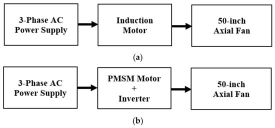
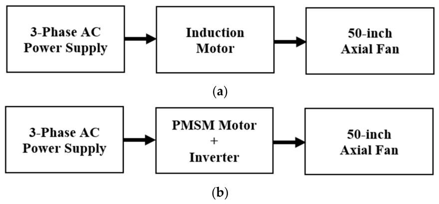
In typical agricultural installations, ventilation fans with diameters around 50 inches (approximately 1.27 m) are commonly used due to their ability to deliver large airflow volumes at relatively low rotational speeds. However, the large fan diameter inherently requires high torque at low rotational speeds, which presents significant challenges for conventional motor drives. Many existing systems employ multi-pole induction motors operating directly from the power grid at a fixed frequency. As illustrated in Figure 1a, the commercial ventilation system typically consists of a three-phase AC supply driving an induction motor connected directly to a large axial fan. Although induction motors [1,2,3] are robust and widely used in industrial applications, their fixed speed operation limits their ability to match ventilation demand under varying farm conditions.
Figure 1.
Direct-drive ventilation system using (a) an induction motor and (b) a PMSM.
In contrast, inverter-fed permanent magnet synchronous motors (PMSMs) enable flexible speed control and improved torque density, making them suitable for demand following ventilation applications. As shown in Figure 1b, the proposed system replaces the commercial induction motor with a direct-drive PMSM controlled by an inverter, allowing continuous speed regulation within the operational range required by agricultural ventilation systems. This demand following capability is particularly important for large axial fans where airflow and power consumption strongly depend on rotational speed.
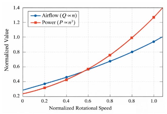
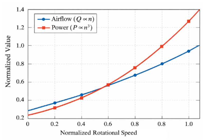
The physical relationship between airflow and fan speed can be explained using fan affinity laws. For geometrically similar fans operating under similar aerodynamic conditions, the airflow rate is proportional to rotational speed, while the input power is proportional to the cube of speed. Figure 2 illustrates the normalized relationship between rotational speed, airflow, and input power according to fan affinity laws. This cubic relationship indicates that small reductions in rotational speed can significantly reduce power consumption. Consequently, the ability to regulate motor speed according to ventilation demand can substantially improve the overall energy efficiency [4,5] of agricultural ventilation systems.
Figure 2.
Normalized relationship between rotational speed, airflow, and input power.
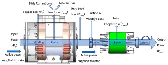
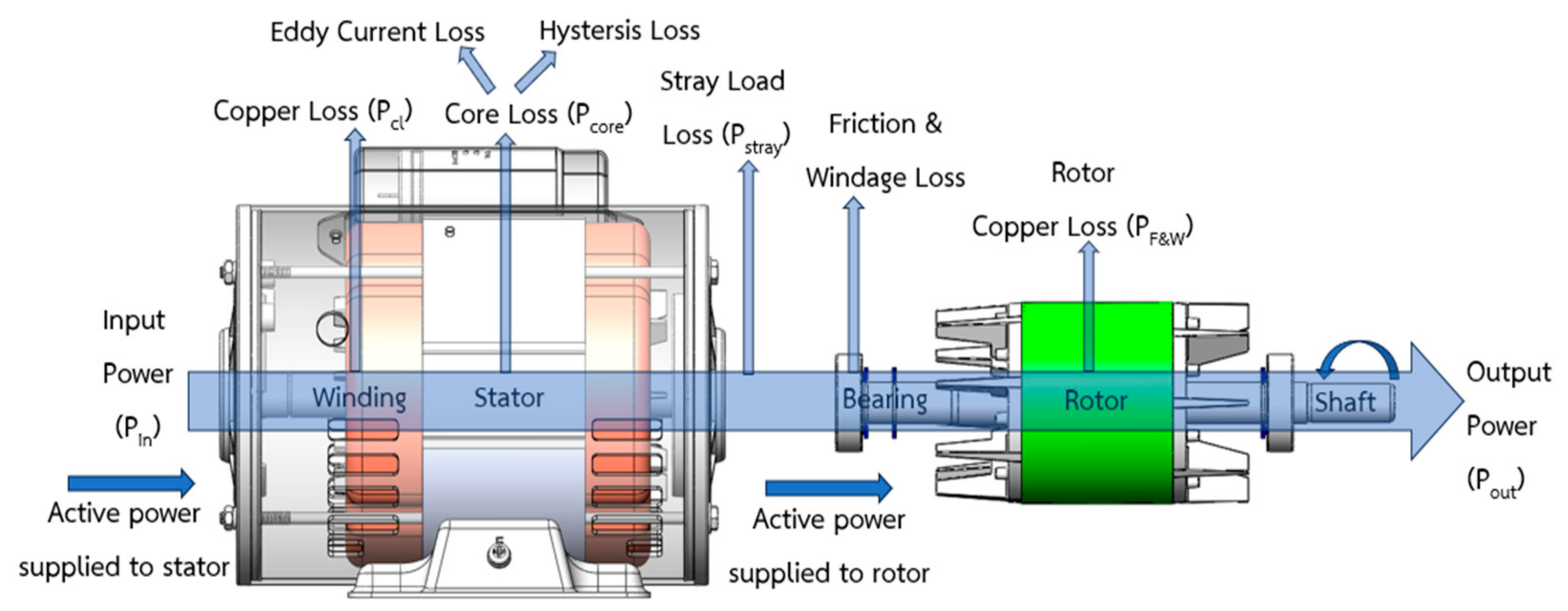
Despite the advantages of variable-speed operation, commercial ventilation systems based on induction motors exhibit several fundamental limitations under low-speed, high-torque conditions. When induction motors operate under increasing mechanical load, the rotor speed decreases relative to the synchronous speed, resulting in increased slip. This slip generates rotor currents that produce torque but simultaneously introduce rotor copper losses. The magnitude of rotor copper loss increases proportionally with slip, leading to substantial efficiency degradation under heavy load conditions. Figure 3 conceptually illustrates the slip-dependent loss mechanism in induction motors. Under high-torque conditions, slip levels can exceed 20%, resulting in significant rotor heating and reduced energy efficiency within the operating region most relevant to agricultural ventilation.
Figure 3.
Conceptual power flow and loss components in an induction motor, highlighting the slip-dependent rotor copper loss mechanism.
Permanent magnet synchronous motors provide a fundamentally different torque production mechanism that eliminates slip-dependent rotor copper losses. In PMSMs, torque is generated through the interaction between stator current [6,7,8] and permanent magnet flux, allowing synchronous operation without rotor current induction. As a result, PMSMs inherently avoid rotor copper loss [9,10] and can maintain higher efficiency across a broader operating envelope compared with induction motors. These characteristics make PMSMs attractive candidates for direct-drive fan applications requiring high torque at relatively low speeds.
However, the practical adoption of PMSMs in existing agricultural ventilation systems is often limited by manufacturing constraints. Many agricultural motor platforms have established production lines designed for induction motors, including stator lamination dimensions, housing structures, winding equipment, and assembly processes. Developing an entirely new motor platform can introduce substantial tooling costs and production risks. Therefore, an important challenge in industrial motor development is how to upgrade existing induction motor platforms to PMSM technology [11,12] while preserving key manufacturing infrastructure.
This study addresses this challenge by proposing a manufacturing constrained conversion framework that transforms a commercial induction motor platform into a direct-drive surface PMSM. Instead of developing a completely new motor platform, the proposed design reuses the original stator outer diameter, housing structure, and winding production process while redesigning the rotor to incorporate surface-mounted permanent magnets [13]. By maintaining compatibility with existing manufacturing processes, the conversion strategy minimizes tooling modification while enabling a high-efficiency direct-drive operation.
To validate the proposed approach, comprehensive experimental testing was conducted on both the commercial induction motor and the converted PMSM prototype. The commercial induction motor baseline was characterized through multi-point load testing to identify slip-dependent efficiency degradation. The proposed PMSM prototype was evaluated through multi-speed efficiency mapping within the practical ventilation operating range of 650–750 rpm. The experimental results demonstrate that the PMSM significantly expands the high-efficiency operating envelope compared with the commercial induction motor system while enabling flexible demand following speed control.
The main contributions of this work are as follows:
- Experimental identification of slip-dominated loss mechanisms in a commercial induction motor driving a large-diameter axial fan.
- Development of a manufacturing constrained induction to surface PMSM conversion methodology.
- Comparative analysis of electromagnetic loss redistribution between induction and permanent magnet torque production mechanisms [14,15].
- Multi-speed efficiency validation of a demand following direct-drive PMSM within real ventilation operating conditions.
- System-level analysis linking ventilation demand, fan affinity laws, and electrical efficiency improvement.
Unlike conventional motor design studies [16,17,18,19] that focus on unconstrained electromagnetic optimization, this work emphasizes a manufacturing-constrained conversion framework that preserves existing industrial infrastructure. This approach enables practical implementation while maintaining significant efficiency improvement, thereby addressing the gap between theoretical motor design and real-world industrial deployment.
2. Materials and Methods
2.1. Literature Background and Theoretical Basis
The design of energy-efficient electric drives for large-diameter ventilation fans has attracted increasing attention in agricultural and industrial applications. Poultry houses, livestock facilities, and greenhouse ventilation systems require continuous airflow regulation to maintain appropriate thermal comfort, humidity control, and air quality. As illustrated in Figure 4, ventilation fans in such applications are commonly driven by electric motors operating in the low-speed, high-torque region [20,21,22]. Consequently, the selection of motor topology and drive configuration significantly affects system efficiency and operational flexibility.
Figure 4.
Application for ventilation fans.
2.1.1. Direct-Drive PMSMs for Ventilation and Fan Applications
Permanent magnet synchronous motors (PMSMs) have become increasingly attractive for applications requiring high-torque density and high efficiency over a wide operating range. Compared with conventional induction motors, PMSMs generate torque through the interaction between stator current and the magnetic field produced by permanent magnets. This mechanism eliminates the need for rotor current induction, which in turn removes rotor copper losses associated with slip.
Several studies have investigated the application of PMSMs in fan and ventilation systems due to their superior efficiency and controllability. Direct-drive PMSM solutions eliminate mechanical transmission components such as gearboxes or belt drives, thereby reducing mechanical losses and maintenance requirements. Furthermore, PMSMs can operate efficiently over a wide speed range when combined with inverter-based control, enabling demand following operation that is particularly beneficial in ventilation systems where airflow demand varies with environmental conditions.
For large-diameter axial fans used in agricultural ventilation, direct-drive PMSMs offer several advantages. First, the high-torque density of PMSMs enables direct coupling between the motor shaft and the fan without intermediate transmission mechanisms. Second, inverter-fed PMSMs allow continuous speed regulation, enabling the fan to operate at different airflow levels depending on the ventilation requirements. Despite these advantages, practical implementation of PMSM solutions in existing ventilation systems remains limited in many agricultural facilities because commercial installations are often based on standardized induction motor platforms with well-established manufacturing processes.
2.1.2. Induction Motor Loss Under Low-Speed, High-Torque Operation
Induction motors remain widely used in industrial applications due to their robustness, simplicity, and cost-effectiveness. However, their performance [23,24,25] under low-speed, high-torque operating conditions is inherently limited by slip-dependent loss mechanisms.
The synchronous speed of an induction motor is determined by the supply frequency and the number of poles according to Equation (1):
where is the synchronous speed in revolutions per minute, is the electrical frequency, and is the number of poles.
Under load conditions, the rotor rotates at a slightly lower speed than the synchronous speed. The difference between these two speeds is defined as the slip according to Equation (2):
where is the rotor speed. Slip is necessary for torque production in induction motors, but it also introduces additional electrical losses in the rotor conductors.
In contrast, limited attention has been given to improving efficiency under **manufacturing-constrained conditions**, where the stator geometry, housing, and production infrastructure must be preserved. This constraint is particularly relevant in industrial retrofit scenarios, where replacing the entire motor system is not economically feasible.
Therefore, there remains a gap in developing approaches that simultaneously:
- (i)
- Mitigate slip-dependent losses;
- (ii)
- Operate efficiently under low-speed, high-torque conditions;
- (iii)
- Maintain compatibility with existing manufacturing infrastructure.
This limitation motivates the present study, which proposes a manufacturing-constrained conversion from an induction motor to a PMSM, enabling improved efficiency through the elimination of slip-dependent loss mechanisms while preserving the original stator platform.
2.1.3. Fan Affinity Laws and Ventilation Demand
The operating characteristics of ventilation systems are governed not only by motor performance but also by the aerodynamic behavior of the fan. For geometrically similar fans operating in similar flow regimes, fan affinity laws describe the relationship between rotational speed, airflow rate, pressure rise, and power consumption as follows:
- Equation (3):
- Equation (4):
- Equation (5):
The cubic relationship between power consumption and rotational speed indicates that small changes in fan speed can lead to significant changes in power demand. This principle forms the basis of energy efficient ventilation strategies based on variable-speed control.
2.1.4. Manufacturing Constrained Conversion and Research Gap
While the performance advantages of PMSMs are well-recognized, their widespread adoption in existing agricultural ventilation systems is often constrained by manufacturing considerations. Many agricultural motors are produced on established induction motor platforms, where the stator laminations [24,25], housing structures, and winding processes are optimized for large-scale production. Introducing an entirely new motor design may require significant changes to tooling, production equipment, and assembly procedures.
Recent research has therefore explored retrofit and conversion approaches that upgrade existing motor platforms while preserving key manufacturing infrastructure. Nevertheless, most existing studies on PMSM design focus primarily on electromagnetic optimization without considering the constraints imposed by baseline manufacturing platforms. Similarly, many studies on fan drive systems investigate variable-speed operation but do not explicitly examine the conversion of existing induction motor platforms to PMSM architectures.
From the literature reviewed above, three research gaps can be identified. First, relatively few studies investigate the conversion of existing induction motor platforms to PMSM designs under realistic manufacturing constraints. Second, previous studies on ventilation fan applications rarely provide experimental baseline comparisons with commercial induction motor systems. Third, most motor design studies focus primarily on electromagnetic optimization without explicitly linking motor performance to demand following ventilation requirements governed by fan affinity laws.
To address these gaps, the present work investigates a manufacturing constrained conversion of an existing induction motor platform to a direct-drive surface PMSM designed for large-diameter agricultural ventilation fans. By combining experimental baseline measurements of the induction motor with efficiency mapping of the proposed PMSM prototype, this study provides a comprehensive analysis of efficiency improvement and loss redistribution in a practical ventilation application.
2.2. Motor Platform and Conversion Methodology
This section describes the design framework used to convert a baseline induction-motor platform into a direct-drive surface PMSM suitable for large-diameter agricultural ventilation fans. Unlike conventional PMSM design approaches that begin with a completely new electromagnetic structure, the proposed method is constrained by existing manufacturing infrastructure. Therefore, the design process focuses on reusing the original induction motor platform while modifying only a limited number of key components. The conversion strategy consists of three major stages: identification of the existing motor platform, definition of manufacturing constraints, and redesign of the electromagnetic structure to enable PMSM operation.
2.2.1. Commercial Induction Motor Platform
The baseline system used in this study is a multi-pole three-phase induction motor platform commonly deployed in agricultural ventilation applications. These motors typically drive large-diameter axial fans operating at relatively low rotational speeds. The existing motor platform includes two main configurations: a 6-pole induction motor and an 8-pole induction motor. Both configurations share a common mechanical platform designed for industrial production. The platform includes a standardized stator lamination, housing structure, and winding manufacturing process [16,21].
Table 1 summarizes the key design parameters of the baseline induction motors and the converted PMSM prototype.
Table 1.
Design parameters of commercial induction motors and the converted PMSM prototype.
The most important features of the existing platform include a common stator outer diameter, a common motor housing and mechanical interface, and an existing winding production process. Because the stator, housing, and manufacturing process remain unchanged, the baseline induction motor platform provides a practical foundation for developing a PMSM solution under industrial production constraints.
2.2.2. Manufacturing Constraints
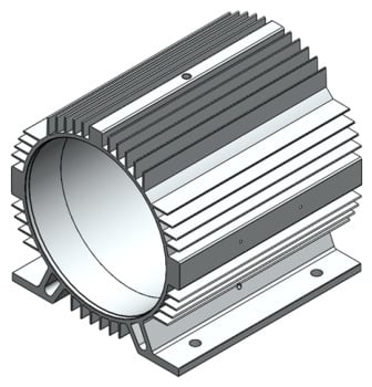
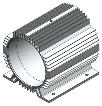
A key novelty of the proposed design lies in the manufacturing constrained conversion framework. Instead of designing a completely new motor structure, the PMSM is developed under strict constraints imposed by the commercial induction motor platform. The original motor housing is retained to preserve mechanical compatibility with the existing agricultural ventilation system. The reused housing structure is shown in Figure 5.
Figure 5.
Motor housing structure reused from the commercial induction motor platform in the converted PMSM design.
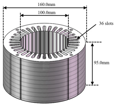
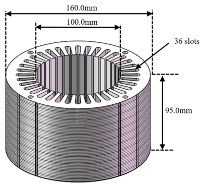
The stator lamination geometry of the original commercial induction motor platform is also preserved. Key stator parameters, including outer diameter, inner diameter, slot structure, and stack length, remain unchanged. The dimensions of the reused stator structure are illustrated in Figure 6, where the stator outer diameter is 160 mm, the inner diameter is 100 mm, the stack length is 95 mm, and the stator contains 36 slots.
Figure 6.
Reused stator lamination geometry of the commercial induction motor platform (outer diameter 160 mm, inner diameter 100 mm, stack length 95 mm, and 36 slots).
The existing winding production process must also be preserved. Only a limited number of components are modified during the conversion process, including the rotor electromagnetic structure [23], wire diameter, number of turns, and winding connection scheme. By limiting the design modifications to these elements, the conversion strategy enables the reuse of most mechanical components and manufacturing processes of the baseline motor platform.
2.2.3. Rotor Conversion and Inverter-Based Direct Drive
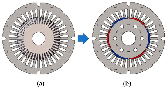
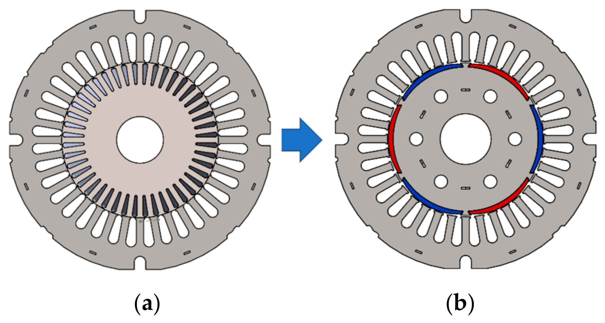
The conversion of the baseline induction motor platform to a PMSM prototype follows a systematic procedure. In the proposed conversion framework, the rotor of the original induction motor was redesigned to enable synchronous operation while maintaining compatibility with the existing stator geometry. The original rotor of the commercial induction motor employed a conventional squirrel cage structure in which electromagnetic torque was produced through currents induced in the rotor bars [14,19,23]. To achieve synchronous torque production, the squirrel cage rotor was replaced with a surface permanent magnet rotor configuration, as illustrated in Figure 7.
Figure 7.
Comparison of rotor structures: (a) squirrel cage rotor and (b) permanent magnet rotor with alternating north (red) and south (blue) magnet poles.
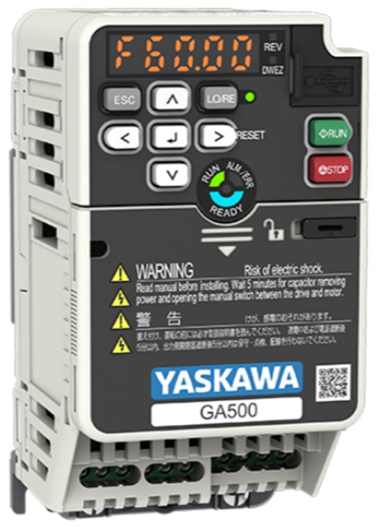
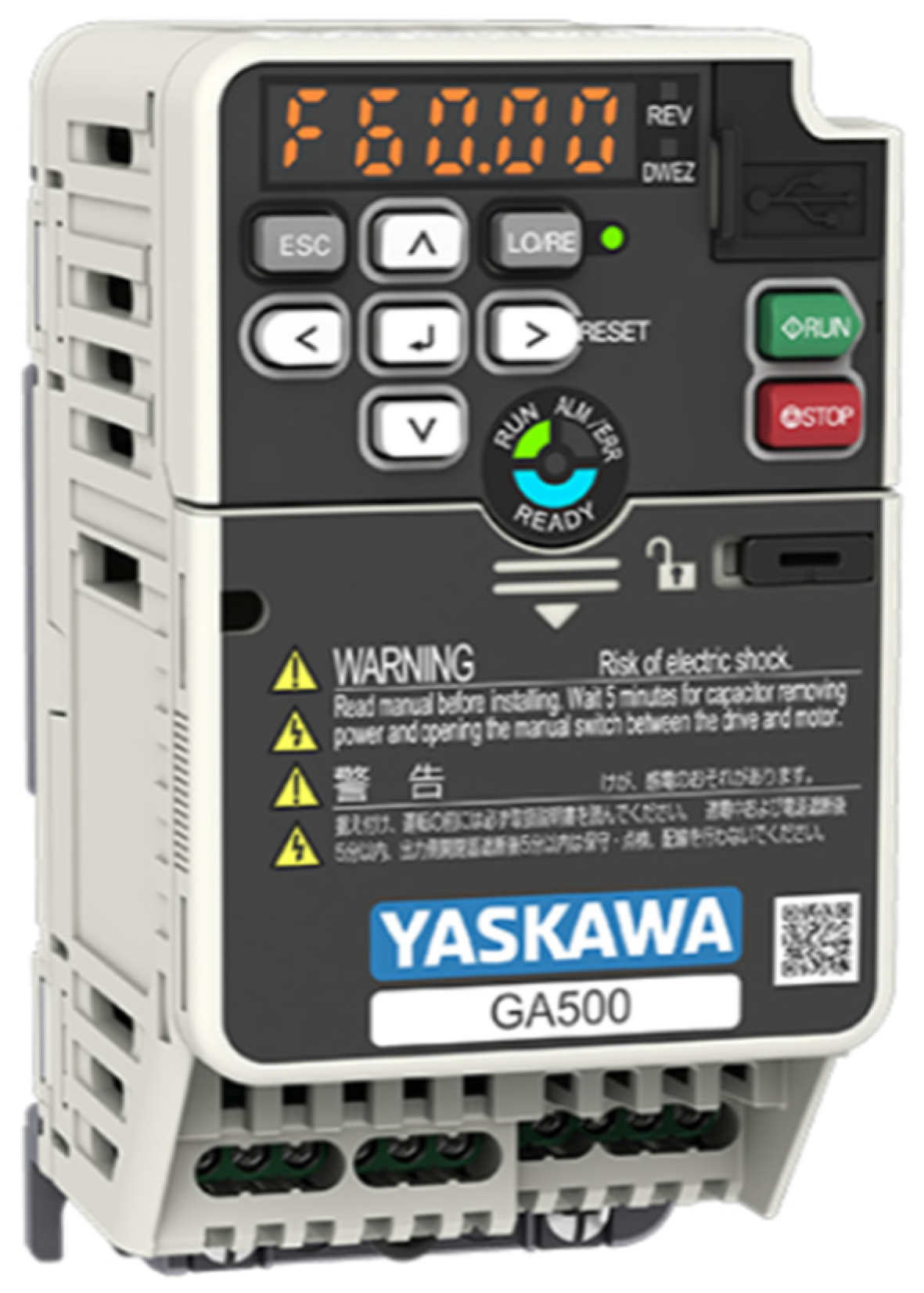
Because PMSM operation requires different electromagnetic characteristics compared with induction motors, the stator winding parameters were modified while preserving the original stator slot structure. The main adjustments included the number of turns, wire diameter, and phase connection configuration. In addition, the converted PMSM was operated using an inverter drive to enable variable-speed control. A commercially available inverter drive was used to control the PMSM prototype, as shown in Figure 8.
Figure 8.
Commercial inverter drive used for PMSM control in the experimental system.
This inverter-based control enables the PMSM to operate within the required speed range of approximately 650–750 rpm, which corresponds to the typical operating range of large-diameter axial ventilation fans. By regulating the inverter output frequency, the motor speed could be adjusted to follow ventilation demand under different environmental conditions.
2.2.4. Prototype Fabrication
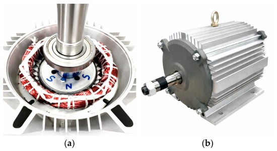
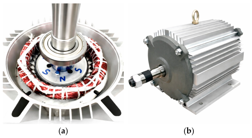
Finally, the PMSM prototype was fabricated based on the existing induction motor platform while incorporating the redesigned permanent magnet rotor and modified stator winding parameters [16,21]. During the fabrication process, the original motor housing, stator lamination [24,25], and mechanical mounting interfaces were preserved in order to maintain compatibility with the existing ventilation fan system. The stator winding implementation of the converted PMSM and the fully assembled PMSM prototype are shown in Figure 9.
Figure 9.
Prototype fabrication of the converted PMSM: (a) stator winding implementation; (b) assembled PMSM prototype.
2.3. Physics-Based Design Considerations
2.3.1. Pole and Slot Configuration
The pole number and stator slot structure significantly influence torque production and back EMF characteristics [20,21]. The converted PMSM adopted a 6-pole, 36-slot configurations to achieve the required operating speed range for large axial ventilation fans.
2.3.2. Winding Layout
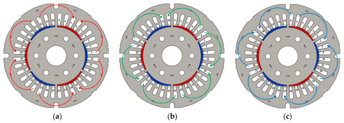
The stator winding of the converted PMSM adopts a distributed three-phase winding configuration designed to be fully compatible with the original stator lamination and existing manufacturing process. The winding layout was implemented based on a 6-pole, 36-slot configuration, resulting in a slots-per-pole-per-phase (q) value of 2, which ensured a balanced three-phase system and reduced harmonic content in the air gap magnetic field.
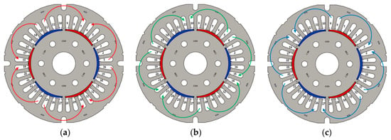
Figure 10 illustrates the detailed winding distribution for each phase. The stator slots are symmetrically arranged, and the three-phase windings are spatially shifted by 120 electrical degrees to achieve balanced electromagnetic operation.
Figure 10.
Distributed three-phase winding layout of the 6-pole, 36-slot stator: (a) Phase A (red), (b) Phase B (green), and (c) Phase C (blue). The arrows indicate winding direction, and the windings are spatially shifted by 120 electrical degrees to produce a balanced rotating magnetic field and reduce harmonic distortion.
In Figure 10a, Phase A windings are distributed across the stator slots with alternating coil directions to form a sinusoidal magnetomotive force (MMF) distribution. Figure 10b and Figure 10c show the corresponding winding layouts for Phase B and Phase C, respectively, each shifted by 120 electrical degrees relative to Phase A.
The distributed winding configuration improves the spatial distribution of the MMF and reduces space harmonics compared to concentrated winding structures. This is particularly important for PMSM operation, as it contributes to smoother torque production, reduced torque ripple, and improved efficiency.
Furthermore, by preserving the original slot geometry and adapting the winding distribution within the existing stator structure, the design maintains full compatibility with current manufacturing processes. This approach supports the manufacturing-constrained design framework proposed in this study, enabling performance improvement without requiring major modifications to tooling or production infrastructure.
2.3.3. Permanent Magnet Sizing
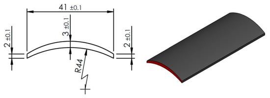
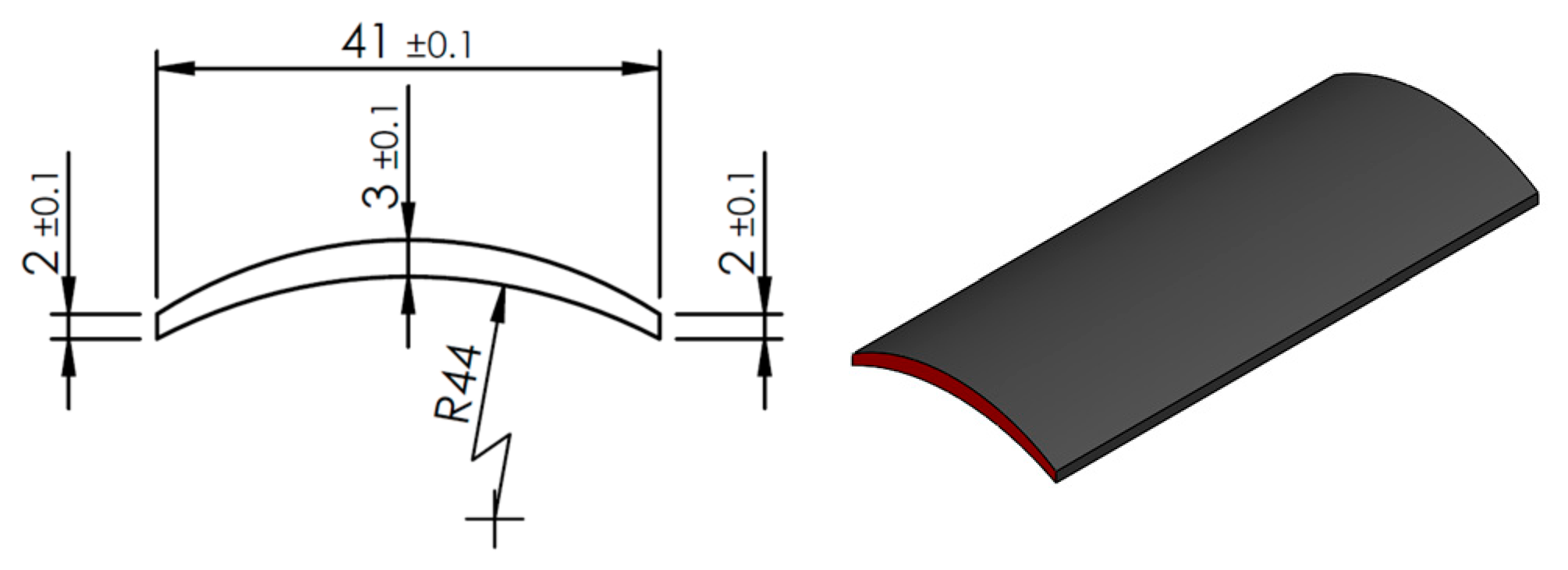
The dimensions and placement of the surface permanent magnets were determined to provide sufficient air gap magnetic flux for torque production [20,21] while maintaining compatibility with the existing stator geometry. The selected magnet dimensions were 41 mm in width, 97 mm in arc length, and 2 mm in thickness, as illustrated in Figure 11.
Figure 11.
Permanent magnet dimensions: width 41 mm, length 97 mm, and thickness 2 mm.
2.3.4. Air Gap Geometry
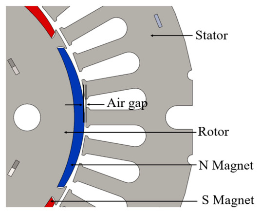
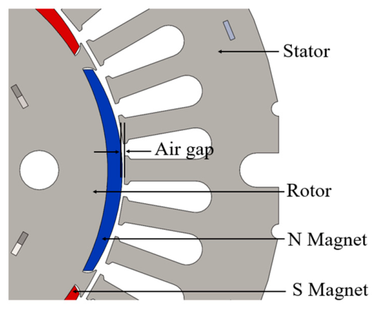
The air gap length and rotor diameter must be carefully selected to maintain an appropriate balance between electromagnetic performance and mechanical tolerance. Based on the mechanical tolerances of the reused stator structure and the required electromagnetic coupling for direct-drive fan operation, the air gap length was selected as 0.5 mm, as illustrated in Figure 12.
Figure 12.
Air gap length of 0.5 mm.
2.3.5. Back EMF Design Target and Torque Density
The back-electromotive force (back EMF) constant of the converted PMSM was designed to be compatible with the voltage capability of the inverter drive while supporting the target operating speed range of the agricultural ventilation system. Based on the design target, the measured line-to-line back EMF of the prototype PMSM is approximately 308 Vrms at the rated speed condition. This value confirms that the selected magnet dimensions and winding configuration provide a suitable balance between torque capability and inverter voltage margin for direct-drive ventilation operation.
Because the motor must drive a large axial fan directly, the torque density requirement is higher than in many standard industrial motor applications. The PMSM design therefore aims to achieve sufficient torque at rotational speeds between approximately 650 rpm and 750 rpm.
2.4. Experimental Setup and Measurement Procedure
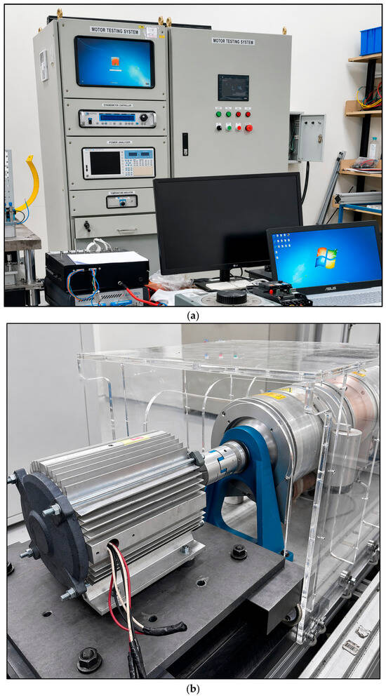
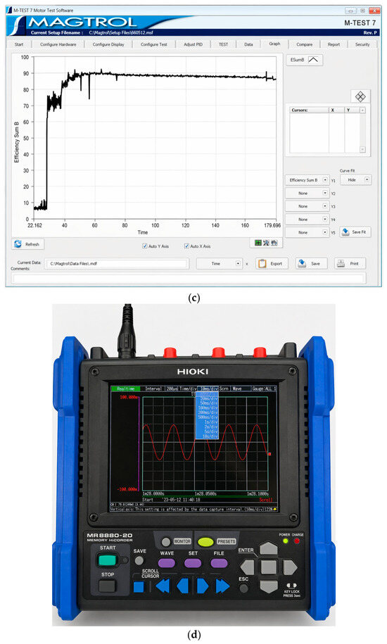
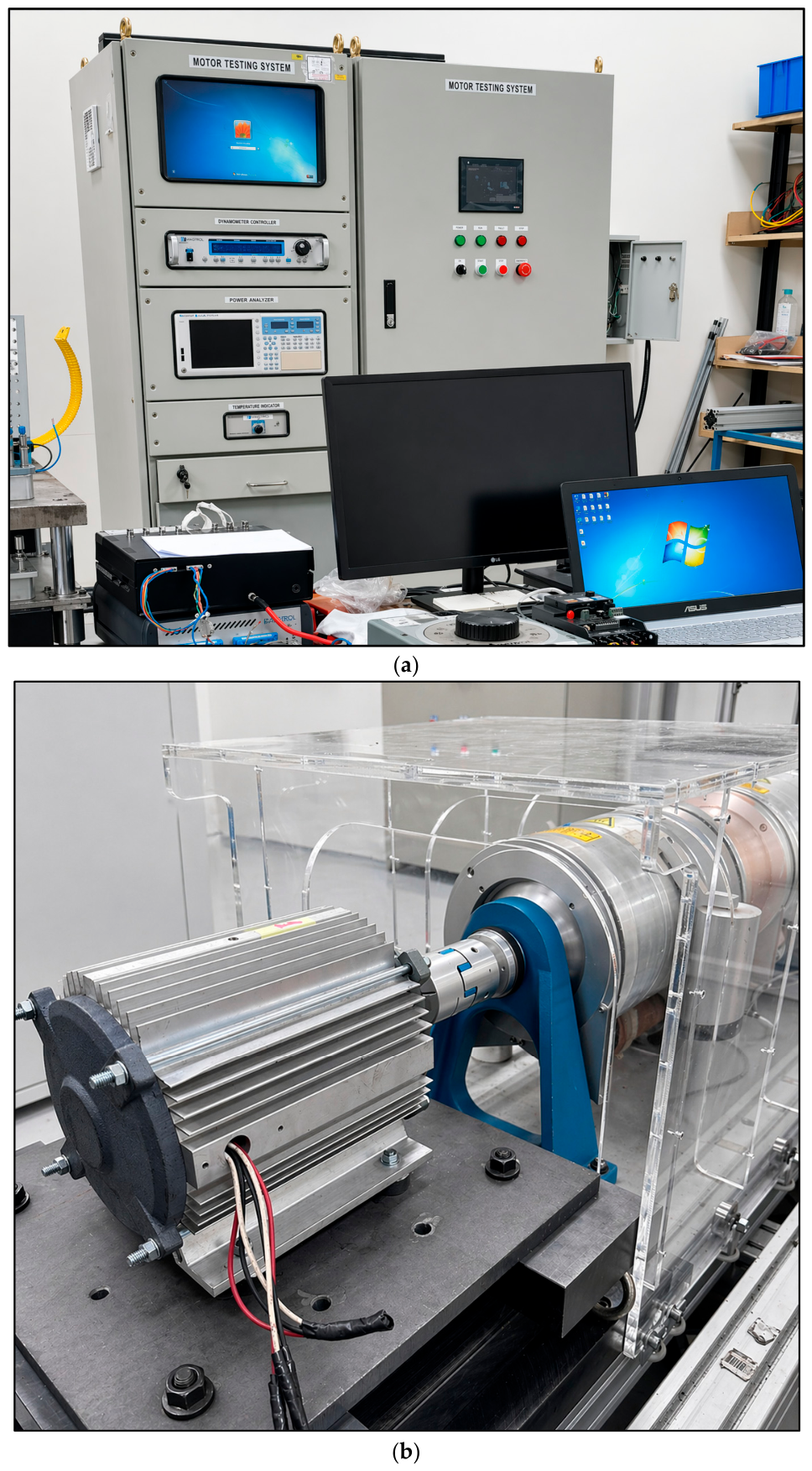
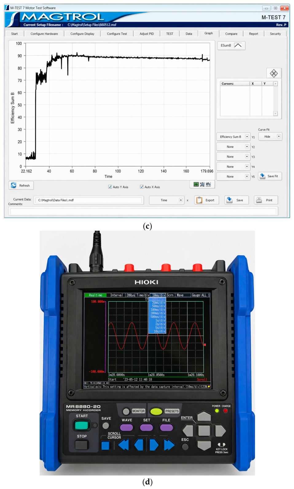
The motor performance tests were conducted using a dynamometer-based measurement system designed for electric motor characterization. The system allows controlled loading of the motor while measuring electrical and mechanical quantities required for efficiency analysis. The main components of the measurement system include power-measurement instruments, a dynamometer test machine, a torque and speed measurement system, an inverter drive controller for PMSM testing, and Magtrol data acquisition software (M-Test 7 Motor Testing Software).
Figure 13 shows the complete experimental setup used in this study, including the power measurement instruments and control system, the PMSM prototype mounted on the dynamometer test bench, the Magtrol interface, and the back EMF measurement arrangement.
Figure 13.
Experimental setup for motor performance measurement: (a) power measurement instruments and control system; (b) PMSM prototype mounted on the dynamometer test bench; (c) Magtrol interface mounted on the test machine; (d) back EMF measurement.
2.4.1. Commercial Induction Motor Baseline Test
The commercial induction motor serves as the baseline reference for evaluating the performance improvement achieved by the PMSM conversion. The induction motor was operated under fixed-frequency conditions without inverter-based speed control. Mechanical loading was applied using the dynamometer to obtain torque speed performance data across the operating range. During the test procedure, the following quantities were measured: line voltage, phase current, input electrical power, rotational speed, and mechanical torque.
The mechanical output power is calculated using Equation (6):
where is the measured torque (N·m) and is the rotational speed (rpm).
The efficiency of the motor is calculated as follows:
where is the measured electrical input power.
2.4.2. PMSM Prototype Experimental Test
The converted PMSM prototype was evaluated using a similar dynamometer test setup. However, unlike the induction motor, the PMSM operates with an inverter-based drive system that enables variable-speed operation. During PMSM testing, the inverter controller regulated the motor speed to predefined operating points corresponding to the expected ventilation operating range of approximately 650–750 rpm. At each operating point, the dynamometer applied mechanical loading while electrical and mechanical parameters were recorded.
2.4.3. Back EMF Measurement
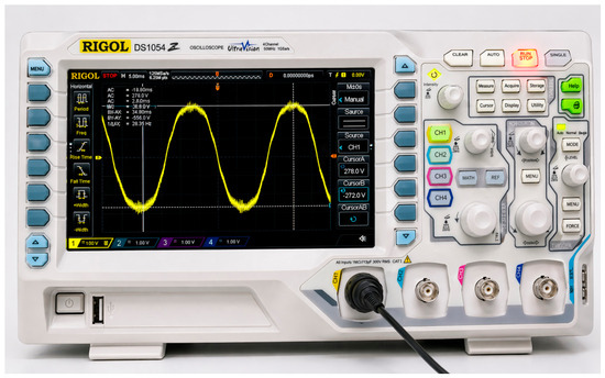
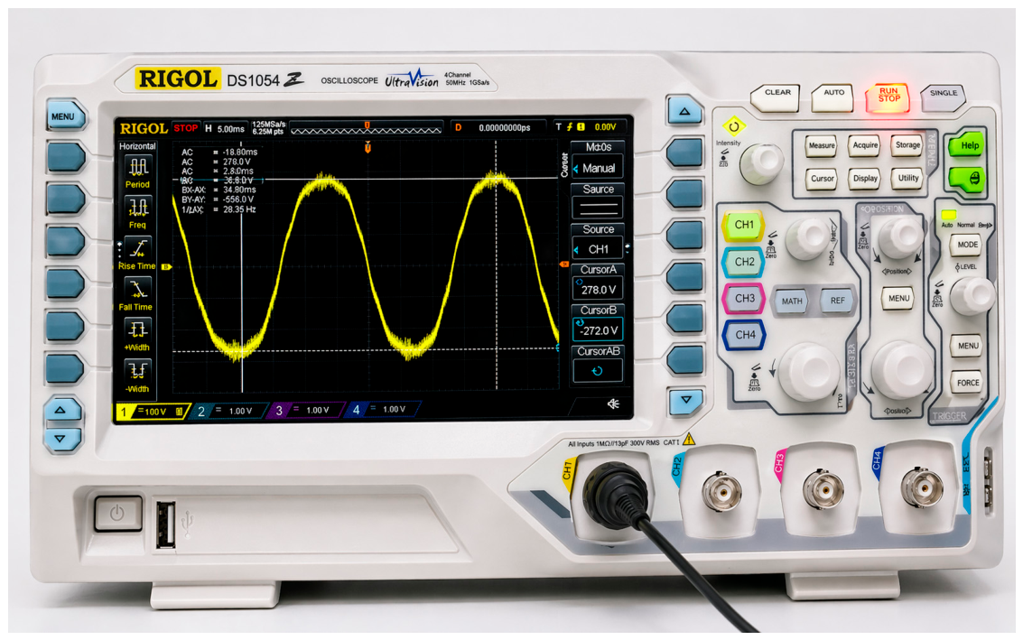
To verify the electromagnetic characteristics of the PMSM prototype, back EMF measurements were conducted by mechanically driving the rotor while leaving the stator windings open-circuited. The induced voltage waveform was measured using an oscilloscope.
As shown in Figure 14, the measured back EMF waveform exhibits a near-sinusoidal shape, indicating that the distributed winding configuration produces a smooth air gap flux distribution with low harmonic distortion.
Figure 14.
Presents the measured back EMF waveform obtained from the oscilloscope. The waveform exhibits a near-sinusoidal shape, indicating good electromagnetic symmetry and low harmonic distortion.
These characteristics are essential for PMSM operation, as they contribute to reduced torque ripple, lower harmonic losses, and improved stability under inverter-driven conditions. The observed behavior is consistent with the winding design described in Section 2.3.2.
2.5. Fair Comparison Framework Considering Drive Conditions
In this study, the performance comparison between the commercial induction motor (IM) and the converted permanent magnet synchronous motor (PMSM) must be carefully interpreted due to the fundamental differences in their operating conditions. The IM operates under a direct grid connection with a fixed frequency, whereas the PMSM is driven by an inverter that enables variable-speed control. As a result, the two systems are not evaluated under identical control conditions.
To address this limitation, the comparison presented in this work is defined as a system-level performance evaluation rather than a purely electromagnetic motor-to-motor comparison. This distinction is essential because, in practical agricultural ventilation applications, motor performance cannot be decoupled from the drive system and operating strategy. In real installations, PMSMs are typically deployed together with inverter-based drives to enable demand following operation, while induction motors are commonly operated under fixed-frequency conditions.
The inverter-fed PMSM provides a key advantage by enabling continuous speed regulation within the required operating range of approximately 650–750 rpm. According to fan affinity laws, airflow is proportional to rotational speed and input power is proportional to the cube of speed. Therefore, the ability to adjust motor speed according to ventilation demand leads to significant reductions in energy consumption under partial load conditions. In contrast, the fixed-speed induction motor cannot adapt to varying airflow requirements and often operates under suboptimal conditions, resulting in increased slip and higher rotor copper losses.
It is also important to note that inverter losses are not explicitly included in the efficiency calculations of the PMSM system in this study. In practical applications, inverter efficiency typically ranges between 95% and 98%, which would slightly reduce the net system efficiency. However, even when considering inverter losses, the PMSM-based system is expected to maintain a significant efficiency advantage due to the elimination of slip-dependent rotor copper losses and the capability for demand-based speed control.
Furthermore, the comparison was performed under equivalent functional requirements rather than identical electrical conditions. Both motor systems were evaluated based on their ability to deliver the required torque and operate within the practical speed range of large-diameter axial ventilation fans. This approach ensures that the comparison reflects realistic application scenarios rather than idealized laboratory conditions.
By explicitly defining the comparison framework in this manner, this study ensures that the reported efficiency improvements are interpreted within the correct context of real-world agricultural ventilation systems. This framework also aligns the evaluation with industrial practice, where motor–drive integration plays a critical role in the overall system performance.
The operating conditions and performance targets used for both motor systems are summarized in Table 2. This table serves as a reference for system-level comparison under practical ventilation requirements rather than identical electrical operating conditions.
Table 2.
Operating performance summary of commercial induction motors and the proposed PMSM under practical ventilation conditions.
The relatively high slip observed in the induction motor is associated with high-torque demand under practical ventilation operating conditions.
3. Results
The experimental results obtained from the dynamometer-based test system were used to evaluate the performance of the converted PMSM prototype and compare it with the commercial induction motor platform. The comparison focuses on efficiency behavior, loss characteristics, and input power consumption under different load and torque conditions relevant to direct-drive ventilation systems. All measurements were conducted across multiple load conditions ranging from 25% to 100% load.
3.1. Measured Performance Data
Table 3 and Table 4 summarize the measured performance data of the baseline induction motors and the converted PMSM prototype under different load conditions. The measurements include load, motor, current, input power, torque, speed, output power, and efficiency for load levels ranging from 25% to 100%.
Table 3.
Measured performance data of the 6-pole induction motor and converted PMSM prototype.
Table 4.
Measured performance data of the 8-pole induction motor and converted PMSM prototype.
These experimentally obtained data serve as the basis for constructing the performance characteristics presented in Figure 15, Figure 16, Figure 17, Figure 18, Figure 19 and Figure 20. To further verify the accuracy and consistency of the measured efficiency values reported in Table 3 and Table 4, an additional validation step is performed using both raw measurement signals and processed data.
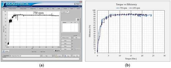
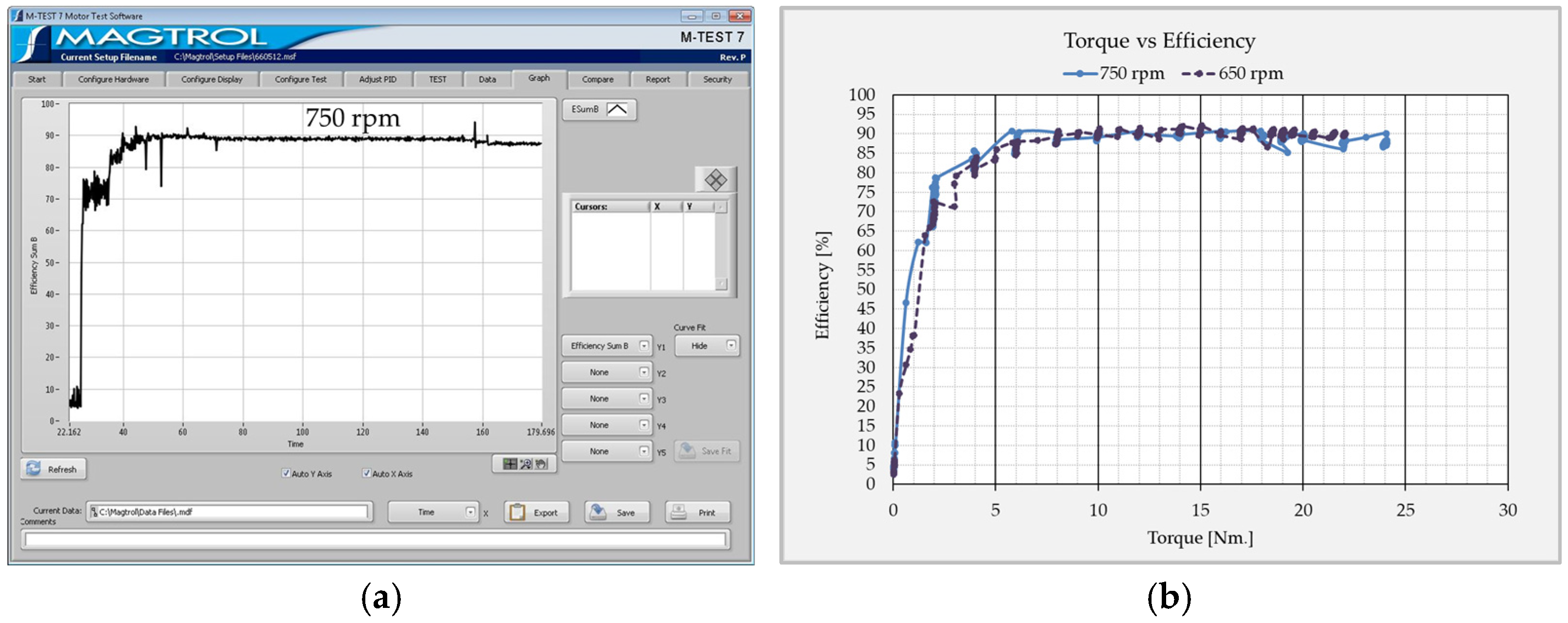
Figure 15.
Validation of PMSM efficiency measurement: (a) real-time efficiency signal obtained from the dynamometer system (MAGTROL), showing the steady-state operating region; (b) efficiency versus torque curve derived from experimentally measured data at 750 rpm. The steady-state efficiency values are consistent with the reported results in Table 3 and Table 4, confirming the accuracy of the calculated efficiency.
Figure 16.
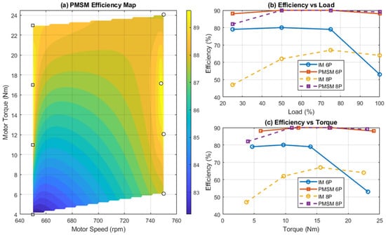
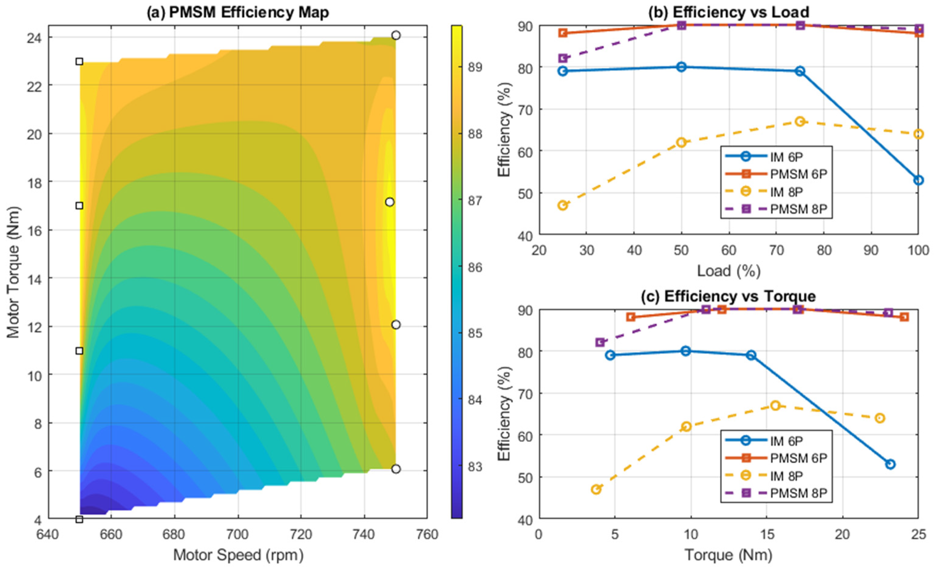
Combined efficiency visualization of the proposed PMSM and baseline induction motors: (a) PMSM efficiency map constructed from experimentally measured torque speed data using interpolation, (b) efficiency versus load, and (c) efficiency versus torque. Circular markers represent induction motor (IM) data, while square markers represent PMSM data.
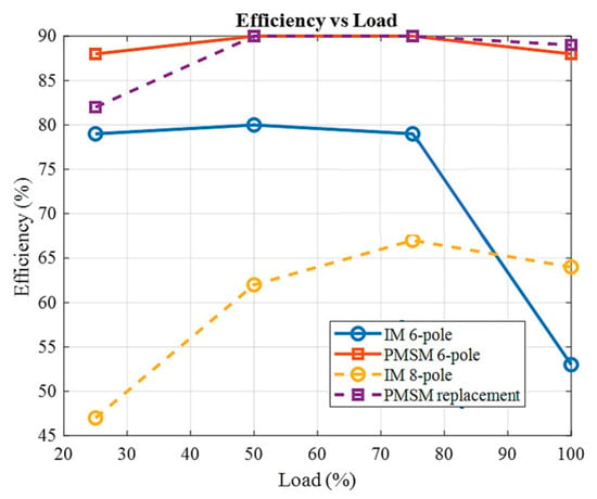
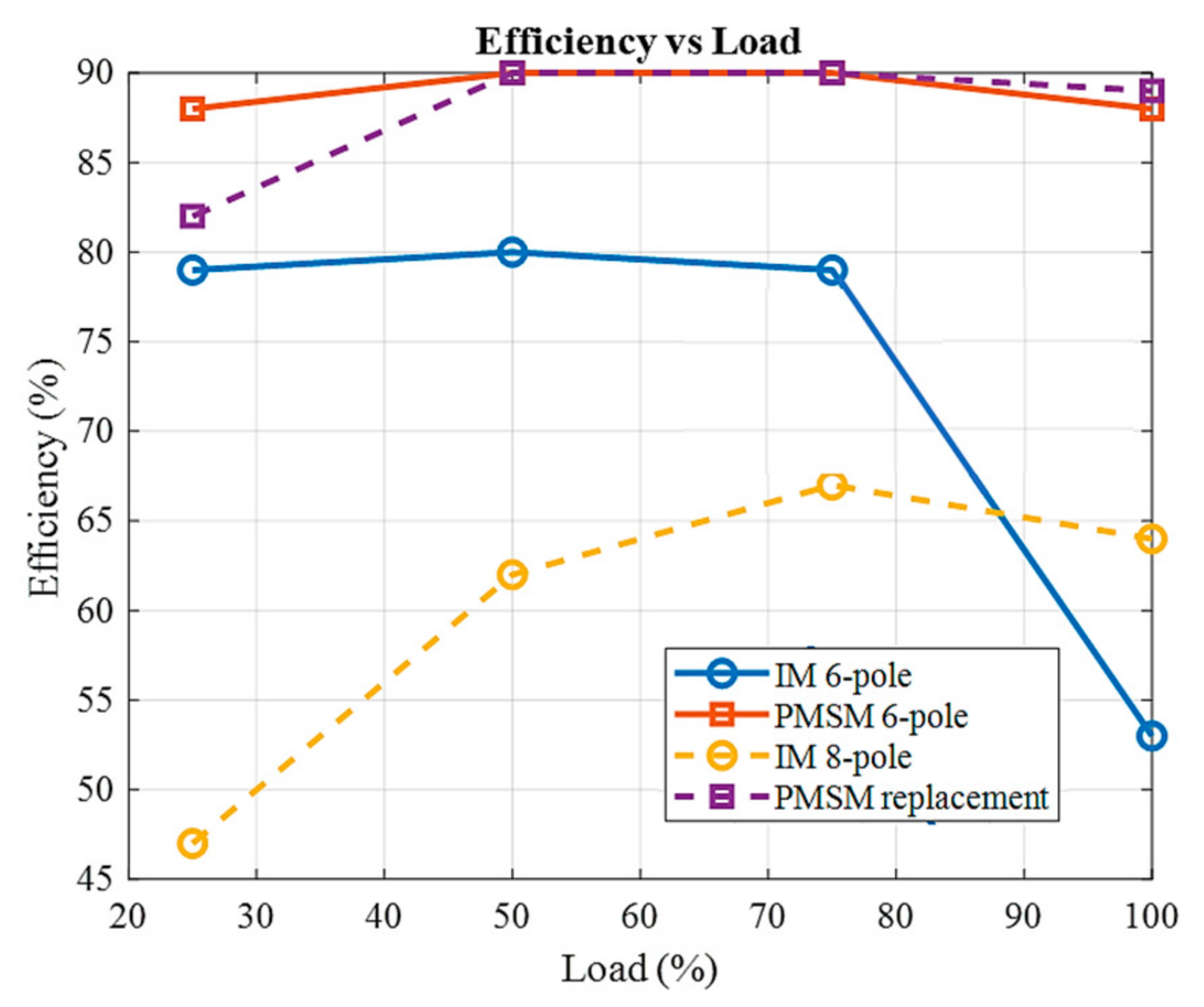
Figure 17.
Efficiency versus load.
Figure 18.
Motor loss versus load.
Figure 19.
Efficiency improvement of the PMSM relative to the induction motor.
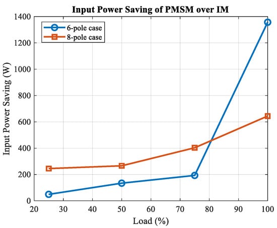
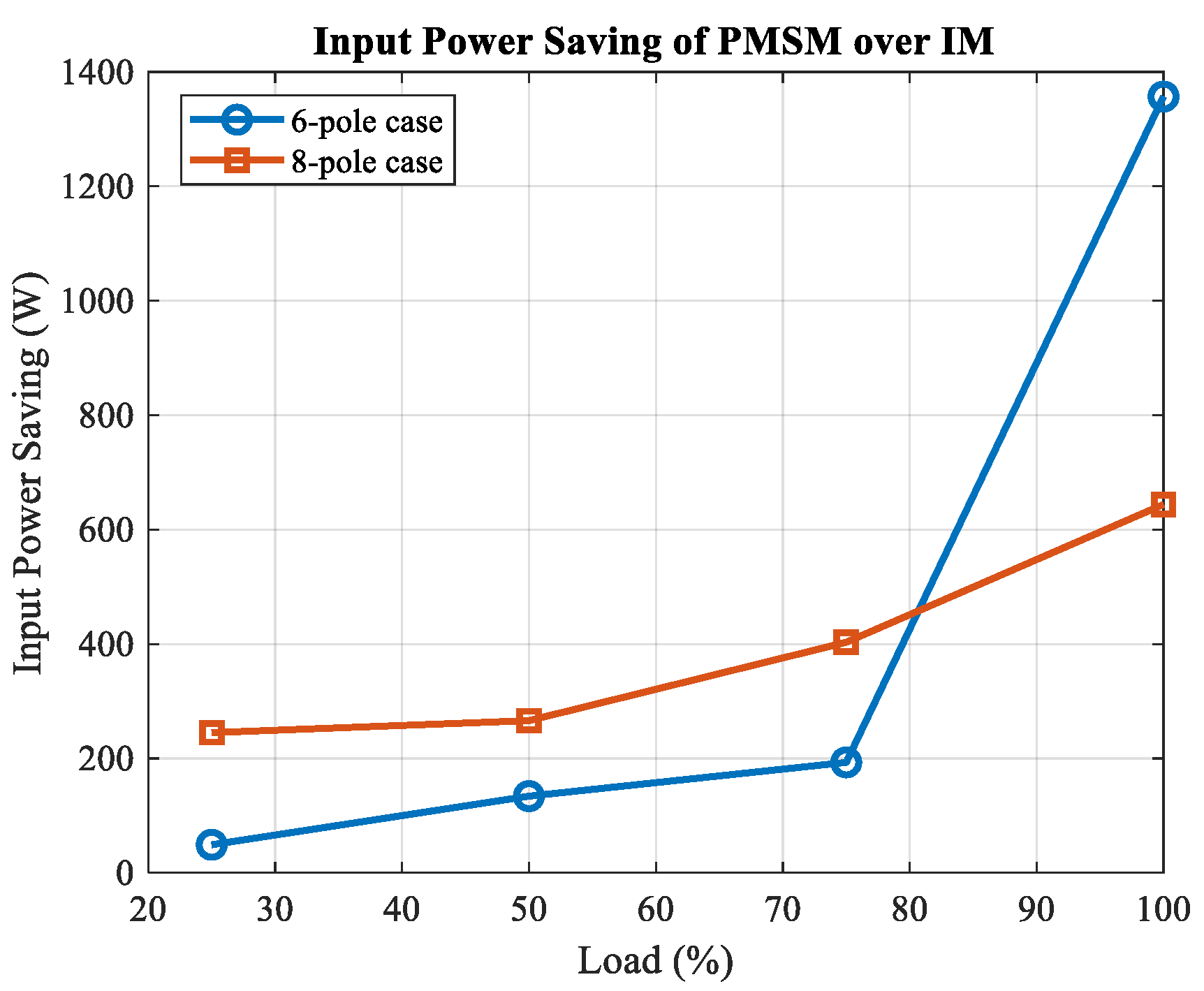
Figure 20.
Input power saving of the PMSM relative to the induction motor.
Figure 15 presents a comparison between the real-time efficiency signal obtained from the dynamometer system and the corresponding efficiency–torque curve derived from the recorded experimental data. This validation ensures that the reported efficiency values are directly traceable to the measured quantities and are not affected by calculation or transcription errors.
As shown in Figure 15a, the measured efficiency signal exhibits a stable steady-state region after transient startup, indicating reliable measurement conditions. The corresponding processed efficiency–torque relationship in Figure 15b confirms that the PMSM maintains efficiency values in the range of approximately 88–90% within the practical operating torque range.
These results are consistent with the efficiency values reported in Table 3 and Table 4, thereby validating the correctness of the calculated efficiency. This cross-verification between raw measurement data and processed results ensures the reliability of the experimental dataset used for subsequent efficiency mapping and performance analysis.
3.2. Combined Efficiency Map and Comparative Performance Analysis
To provide a comprehensive and balanced evaluation of motor performance, the efficiency characteristics of the proposed PMSM and the baseline induction motor (IM) are presented using a combined visualization approach, as shown in Figure 15. This figure integrates (a) a continuous efficiency map of the PMSM and (b) discrete efficiency comparisons between the PMSM and IM as functions of load and torque.
The efficiency map of the PMSM is constructed from experimentally measured operating points obtained from the dynamometer test system. These data points, corresponding to different combinations of torque and speed within the practical ventilation operating range, are interpolated using a grid-based method to generate a continuous efficiency distribution. The resulting map, shown in Figure 16a, illustrates that the PMSM maintains high efficiency across a broad operating region, particularly within the speed range of 650–750 rpm and torque range of approximately 10–24 Nm. In this region, the efficiency consistently exceeds 88% and reaches peak values above 90%, indicating a wide high-efficiency operating envelope.
In contrast, a full efficiency map cannot be constructed for the induction motor due to its fixed-frequency operation, which restricts the motor to a narrow speed range determined by slip. Therefore, the IM performance is evaluated using discrete experimental data, as shown in Figure 16b,c. These plots present efficiency as functions of load and torque, derived directly from the measured data in Table 3 and Table 4.
The comparison reveals a clear difference in efficiency behavior between the two motor types. The PMSM demonstrates consistently high efficiency across the entire load range, maintaining values close to 90% under medium-to-high load conditions. In contrast, the induction motor exhibits a noticeable efficiency drop at higher load levels. This degradation is primarily attributed to increased slip, which leads to higher rotor current and consequently larger rotor copper losses.
The efficiency–torque relationship further highlights this distinction. As torque increases, the efficiency of the induction motor decreases significantly, particularly in the high-torque region relevant to direct-drive ventilation systems. Conversely, the PMSM maintains stable, high efficiency across the same torque range. This behavior is explained by the fundamental difference in torque production mechanisms. In the induction motor, torque generation requires slip, which inherently introduces rotor copper losses proportional to load. In the PMSM, torque is produced through the interaction between the stator current and permanent magnet flux, eliminating slip-dependent losses and enabling a more efficient operation under high-torque conditions.
It is important to interpret these results within the system-level comparison framework defined in Section 2.5. The PMSM operates with inverter-based variable-speed control, allowing it to adjust speed according to ventilation demand, whereas the induction motor operates at a fixed frequency. This difference enables the PMSM to maintain operation within a high-efficiency region over a wider range of operating conditions. According to fan affinity laws, the ability to regulate speed results in significant reductions in input power, particularly under partial-load conditions, further enhancing system-level efficiency.
Overall, the combined visualization demonstrates that the PMSM not only improves peak efficiency but also significantly expands the high-efficiency operating region. This characteristic is particularly beneficial for agricultural ventilation systems, where operating conditions vary continuously and demand following control is essential for energy-efficient operation.
The PMSM demonstrates a broader high-efficiency operating region compared to the induction motor, particularly under high-torque conditions where the induction motor efficiency degrades due to slip-dependent rotor copper losses. This comparison is consistent with the system-level evaluation framework defined in Section 2.5.
To improve the clarity of the performance comparison, the PMSM efficiency map is presented together with discrete efficiency comparisons of the induction motor and PMSM as functions of load and torque. Since the induction motor operates under fixed-frequency conditions, a full torque speed efficiency map cannot be constructed in the same manner as for the inverter-driven PMSM. Therefore, the induction motor performance is presented using experimentally measured discrete operating points, which provide a balanced basis for comparison.
3.3. Efficiency Versus Load
The variation in motor efficiency as a function of load level is shown in Figure 17.
The PMSM prototype consistently demonstrates higher efficiency compared with the induction motor across the entire load range. At medium load levels (50–75%), the PMSM reaches efficiencies close to 90%, while the induction motor remains around 80%. The efficiency difference becomes more significant at higher load conditions, where the efficiency of the induction motor decreases due to increasing slip and the associated rotor copper losses.
3.4. Motor Loss Versus Load
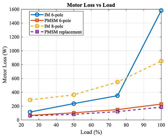
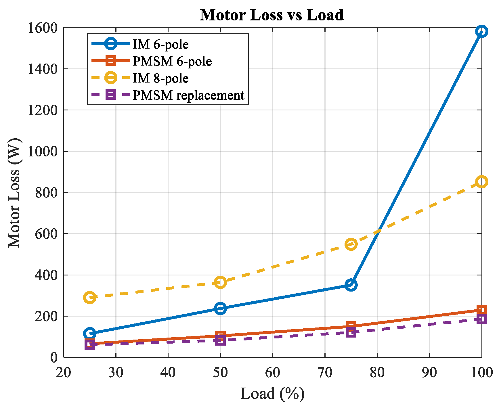
The total motor losses as a function of load are presented in Figure 18.
The results show that the induction motor exhibits a substantial increase in losses as load increases, particularly at higher load levels. This behavior is mainly attributed to rotor copper losses, which increase with slip under higher torque demand. In contrast, the PMSM prototype exhibits significantly lower total losses across the entire load range.
3.5. Efficiency Improvement of PMSM over IM
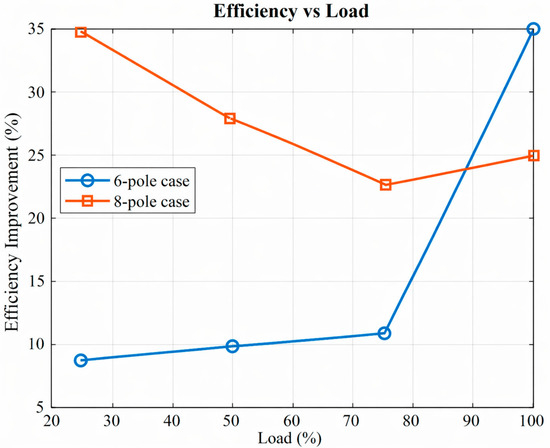
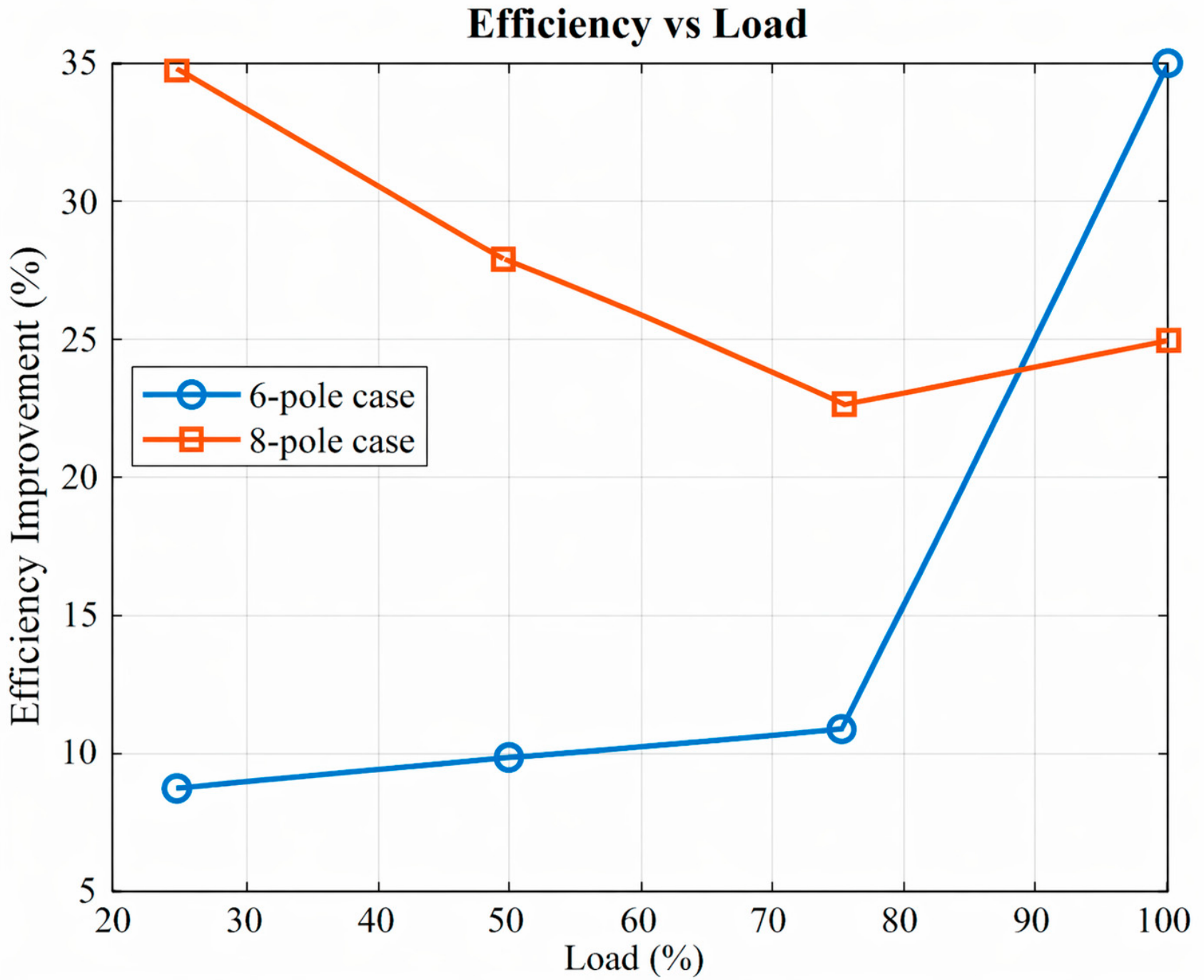
The efficiency improvement achieved by the PMSM relative to the induction motor under different load conditions is shown in Figure 19.
For the 6-pole configuration, the efficiency improvement is relatively moderate at partial load but increases significantly at full load due to the substantial efficiency drop of the induction motor at high load. For the 8-pole configuration, the efficiency improvement remains consistently high across the entire load range.
3.6. Input Power Saving of PMSM over IM
The reduction in electrical input power achieved by replacing the induction motor with the PMSM prototype is shown in Figure 20.
The difference becomes particularly noticeable at higher load levels, where rotor copper losses in the induction motor increase substantially due to higher slip. In contrast, the PMSM maintains lower electrical power consumption because the rotor magnetic field is produced by permanent magnets rather than induced currents.
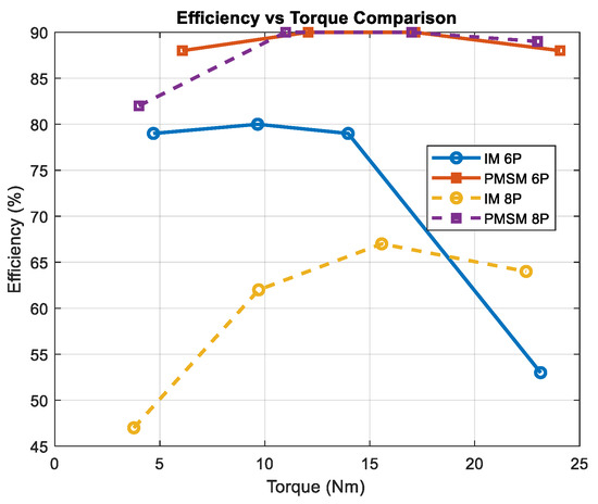
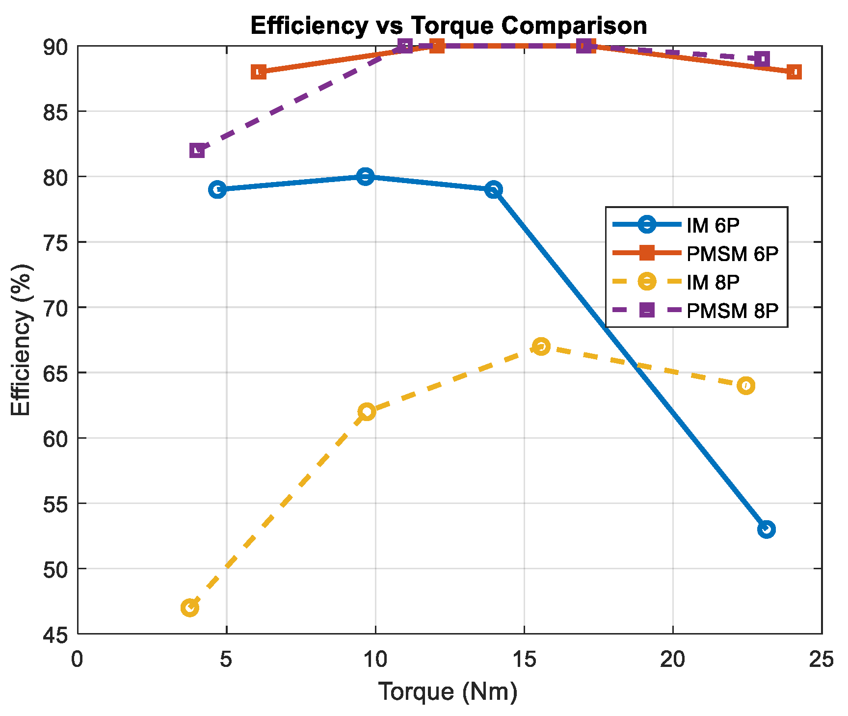
3.7. Efficiency Versus Torque
The relationship between motor efficiency and output torque is shown in Figure 21.
Figure 21.
Efficiency versus torque.
The PMSM maintains high efficiency across a wide torque range, whereas the induction motor efficiency decreases significantly as torque increases. This characteristic is particularly beneficial for direct-drive fan applications, where high torque is required at relatively low rotational speeds.
4. Discussion
The experimental results demonstrate a clear distinction in performance characteristics between the conventional induction motor and the converted PMSM, particularly under operating conditions relevant to large-diameter agricultural ventilation systems. The most notable difference is observed in the efficiency behavior across varying load and torque conditions.
For the induction motor, efficiency degradation becomes significant at higher load levels. This behavior is associated with the inherent operating principle of induction machines, where torque production requires a difference between synchronous speed and rotor speed. As the mechanical load increases, this speed difference becomes larger, leading to increased rotor current and higher associated losses. Consequently, efficiency decreases in the high-torque operating region, which is particularly critical for direct-drive fan applications.
In contrast, the PMSM maintains consistently high efficiency across the entire operating range. This is due to its synchronous operating nature, where torque is generated through the interaction between stator current and the magnetic field of permanent magnets. As a result, the PMSM avoids the loss mechanisms associated with induced rotor currents and demonstrates more stable efficiency characteristics under varying load conditions.
Another important observation is the expansion of the high-efficiency operating region in the PMSM. The efficiency map and comparative plots show that the PMSM is capable of sustaining high efficiency over a wide range of torque values within the practical speed range of 650–750 rpm. This operating region corresponds closely to the typical requirements of agricultural ventilation systems, where high torque at relatively low speeds is required.
From an application perspective, the ability to operate efficiently across a broader range of conditions is highly advantageous. Ventilation demand varies continuously depending on environmental conditions and livestock requirements. The PMSM, when combined with inverter-based control, can adjust its operating speed accordingly. According to fan affinity laws, reducing rotational speed leads to a disproportionate reduction in input power, which enhances overall system efficiency. This effect cannot be fully utilized in fixed-speed induction motor systems.
It should also be noted that the comparison between the two motor types reflects practical operating configurations rather than identical control conditions. The induction motor operates under a fixed-frequency supply, while the PMSM utilizes inverter-based speed control. Therefore, the observed performance differences represent realistic system-level behavior in actual ventilation applications, as discussed in Section 2.5.
Overall, the results indicate that the PMSM not only achieves higher peak efficiency, but also provides superior performance across a wider operating envelope. This characteristic is essential for improving energy efficiency in demand-driven ventilation systems.
Manufacturing-Constrained Design Insight and Novelty
The contribution of this work extends beyond performance comparison by introducing a design framework that explicitly incorporates manufacturing constraints into the motor development process. This perspective is essential for bridging the gap between theoretical motor optimization and practical industrial implementation.
A key contribution of this study lies not only in the performance improvement achieved by the PMSM conversion, but also in the development of a manufacturing constrained design framework that bridges the gap between theoretical motor optimization and practical industrial implementation.
These constraints define the performance boundaries of the design, particularly in terms of magnetic loading, slot utilization, and achievable torque density.
In conventional PMSM design studies, the motor is typically developed from a clean-sheet approach, allowing full freedom in selecting stator geometry, materials, and manufacturing processes. In contrast, the present study is based on an existing commercial induction motor platform, where key components such as stator laminations, housing structure, and winding production processes are preserved. This constraint significantly limits the design space and requires a different engineering strategy.
Under these conditions, performance improvement cannot rely solely on conventional electromagnetic optimization. Instead, the design must focus on selectively modifying critical elements while maintaining compatibility with existing production infrastructure. In this work, the redesign of the rotor structure enables a fundamental shift in torque production mechanism, allowing synchronous operation within the constraints of the original stator configuration.
From a design insight perspective, this approach demonstrates that efficiency improvement can be achieved through a redistribution of loss mechanisms rather than purely through maximizing electromagnetic performance. The transition from induction-based torque production to permanent magnet excitation removes the dependency on rotor-induced currents, thereby reducing loss sensitivity to load variations. This effect becomes particularly important in applications that require sustained operation under high-torque conditions.
The novelty of this work lies in the integration of three key aspects: (1) constraint-aware motor redesign based on an existing industrial platform, (2) experimental validation of performance improvement under realistic operating conditions, and (3) system-level interpretation of efficiency behavior in relation to application requirements. This combination differentiates the present study from prior work that focuses either on unconstrained motor optimization or on application-level analysis without detailed consideration of motor conversion.
From an industrial standpoint, the proposed framework provides a practical pathway for upgrading existing motor systems without significant changes to tooling or manufacturing processes. This reduces implementation complexity and supports faster adoption in real-world applications, particularly in sectors such as agricultural ventilation where cost and reliability are critical.
In summary, this study highlights the importance of integrating manufacturing constraints into motor design and demonstrates that substantial efficiency gains can be achieved through targeted structural modifications aligned with practical production environments.
In contrast to previously reported retrofit approaches, the present work uniquely combines manufacturing-constrained redesign, experimentally validated efficiency mapping, and system-level performance analysis within a single unified framework.
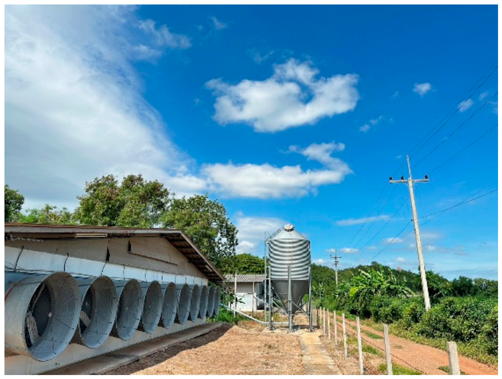
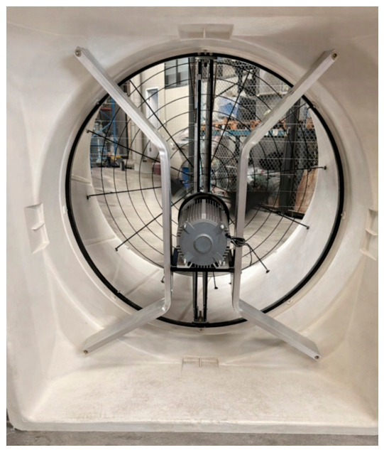
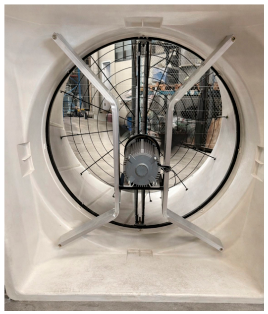
To further demonstrate the practical applicability of the proposed PMSM system, a field-level validation was conducted using a direct-drive axial fan installed in an agricultural ventilation environment, as shown in Figure 22.
Figure 22.
Field validation setup of the PMSM-driven ventilation system, showing the direct-drive axial fan, motor assembly, and structural support integrated within the ventilation housing under practical installation conditions.
The system was operated using an inverter-based drive under near-zero static pressure conditions, which serves as a baseline reference for system behavior. In real operating scenarios, the static pressure typically ranges from 0.10 to 0.25 inch H2O depending on environmental and ventilation requirements.
Although the field conditions are not identical to laboratory-controlled performance testing, the system demonstrates stable and reliable operation under real installation conditions. The observed behavior is consistent with the system-level performance characteristics discussed earlier, particularly the ability of the PMSM to operate efficiently under low-speed, high-torque conditions.
This field validation supports the industrial feasibility of the proposed manufacturing-constrained conversion approach and confirms its applicability in practical ventilation systems.
5. Conclusions
This study presented a manufacturing constrained conversion approach for transforming a commercial induction motor platform into a direct-drive permanent magnet synchronous motor suitable for large-diameter agricultural ventilation systems. The proposed method preserves the existing stator geometry, motor housing, and manufacturing infrastructure while redesigning the rotor structure and stator winding configuration to enable synchronous operation.
Experimental validation using a dynamometer-based test system demonstrates that the converted PMSM consistently achieves higher efficiency than the conventional induction motor across the operating load range. The efficiency advantage becomes more pronounced at higher load conditions, where the induction motor experiences increased slip and corresponding rotor copper losses. The loss analysis further confirmed that the PMSM maintains substantially lower losses due to the elimination of slip-dependent rotor copper losses. As a result, the PMSM prototype shows considerable efficiency improvement, lower input power demand, and a broader high-efficiency operating envelope.
Overall, the results confirm that the proposed manufacturing constrained conversion framework provides a practical pathway for upgrading conventional induction motor platforms to PMSM technology while minimizing manufacturing disruption. The proposed approach offers a promising solution for improving the energy efficiency of industrial ventilation systems and other low-speed, high-torque applications.
Author Contributions
Conceptualization, B.P. and R.R.; methodology, R.R.; validation, R.R., W.W., S.N. and S.P.; formal analysis, R.R. and W.W.; investigation, R.R. and T.M.; resources, W.W. and B.P.; data curation, R.R.; writing—original draft preparation, R.R.; writing—review and editing, B.P. and T.M.; supervision, B.P. All authors have read and agreed to the published version of the manuscript.
Funding
This research has received funding support from the NSRF via the Research and Innovation Acceleration Agency for Competitiveness and Area Development (RCAD) (Program Management Unit for Frontier Brainpower and Future Industries) [grant number B13F690105].
Data Availability Statement
The experimental data and analysis procedures used to support the findings of this study are available from the corresponding authors upon reasonable request.
Acknowledgments
The authors acknowledge the technical support and experimental facilities provided by Rajamangala University of Technology Thanyaburi.
Conflicts of Interest
The authors declare no conflicts of interest.
References
- Ertan, H.B.; Siddique, M.S.; Koushan, S.; Azuaje-Berbecí, B.J. Designing high power density induction motors for electric propulsion. In Proceedings of the IEEE 20th International Power Electronics and Motion Control Conference (PEMC), Brasov, Romania, 25–28 September 2022; pp. 553–558. [Google Scholar] [CrossRef] [Scilit]
- Dems, M.; Komeza, K. Designing an energy-saving induction motor operating in a wide frequency range. IEEE Trans. Ind. Electron. 2022, 69, 4387–4397. [Google Scholar] [CrossRef] [Scilit]
- Popescu, M.; Di Leonardo, L.; Fabri, G.; Volpe, G.; Riviere, N.; Villani, M. Design of induction motors with flat wires and copper rotor for electric vehicle traction systems. IEEE Trans. Ind. Appl. 2023, 59, 3889–3900. [Google Scholar] [CrossRef] [Scilit]
- Deepayan, G.; Goel, S.K. Design optimization of permanent magnet synchronous motor using Taguchi method and experimental validation. Int. J. Emerg. Electr. Power Syst. 2021, 22, 9–20. [Google Scholar] [CrossRef] [Scilit]
- Ozer, K.; Yilmaz, M. Design and optimization of IPMSM for enhanced efficiency, cost reduction, and performance in light electric vehicles. IEEE Access 2025, 13, 80621–80636. [Google Scholar] [CrossRef] [Scilit]
- Chen, P.; Xie, Y.; Li, D. Thermal field and stress analysis of induction motor with stator inter-turn fault. Machines 2022, 10, 504. [Google Scholar] [CrossRef] [Scilit]
- Enokizono, M.; Shimoji, H.; Horibe, T. Effect of stator construction of three-phase induction motors on core loss. IEEE Trans. Magn. 2003, 39, 1484–1487. [Google Scholar] [CrossRef]
- Wu, P.; Sun, Y. A hybrid model for calculating on load performance of delta type IPM machines accounting for rotor and stator saturation. IEEE Trans. Ind. Electron. 2024, 71, 15349–15359. [Google Scholar] [CrossRef] [Scilit]
- Tian, Y.; Liang, S.; Wang, F.; Tian, J.; Chen, K.; Liu, S. Analysis of rotor lamination sleeve loss in high-speed permanent magnet synchronous motor. Machines 2025, 13, 236. [Google Scholar] [CrossRef] [Scilit]
- Siddique, M.S.; Ertan, H.B.; Alam, M.S.; Khan, M.U. Investigation of harmonic losses to reduce rotor copper loss in induction motors for traction applications. World Electr. Veh. J. 2025, 16, 248. [Google Scholar] [CrossRef] [Scilit]
- Hsu, J.S.; Campbell, S.L. Design considerations for PMSM drives in industrial applications. IEEE Trans. Ind. Appl. 2003, 39, 926–933. [Google Scholar]
- Lee, S.-K.; Lee, S.-H.; Jeon, S.-B.; Lim, Y.-R.; Kim, W.-H. Asymmetric permanent magnets for reducing axial leakage flux in double-spoke type PMSM. Machines 2026, 14, 300. [Google Scholar] [CrossRef] [Scilit]
- Ma, Y.; Song, Z.; Liang, Y.; Cao, J. Topology optimization for a spoke-type permanent magnet synchronous motor based on a Siamese convolutional network. In Proceedings of the International Conference on Electrical Machines and Systems (ICEMS), Fukuoka, Japan, 26–29 November 2024; pp. 3346–3351. [Google Scholar] [CrossRef] [Scilit]
- Karatepe, H.C.; Tekgun, B.; Tekgun, D. Design and optimization of an outer rotor spoke type PMSM with improved saliency for a lightweight racing vehicle. In Proceedings of the 7th International Conference on Electric Power and Energy Conversion Systems (EPECS), Sharjah, United Arab Emirates, 12–14 November 2024. [Google Scholar] [CrossRef] [Scilit]
- Prabhu, S.; Vijayakumar, A.; Stonier, A.A.; Peter, G.; Dorji, S.; Ganji, V. Analysis of isolated phase windings and permanent magnet assists high energy efficient hybrid-reluctance motor for electric vehicle. IET Electr. Syst. Transp. 2023, 13, e12081. [Google Scholar] [CrossRef] [Scilit]
- Anthony, Z.; Nazir, R.; Hamid, M.I. An innovative winding configuration to enhance 3-phase induction motor performance. Int. J. Power Electron. Drive Syst. 2026, 17, 82–94. [Google Scholar] [CrossRef] [Scilit]
- Cong, T.T.; Vu, T.N.; Pinto, G.; Quoc, V.D. Optimization design of surface mounted permanent magnet synchronous motors using genetic algorithms. EAI Endorsed Trans. Energy Web 2024, 11, 1–8. [Google Scholar] [CrossRef] [Scilit]
- Sarac, V.; Minovski, D.; Aneva, S.; Janiga, P.; Smitkova, M.F.; Bogatinov, D.; Atanasova, A. Various designs of spoke-type permanent magnet motor for performance optimization. Machines 2025, 13, 375. [Google Scholar] [CrossRef] [Scilit]
- Jung, W.-S.; Lee, H.-K.; Lee, Y.-K.; Kim, S.-M.; Lee, J.-I.; Choi, J.-Y. Analysis and comparison of permanent magnet synchronous motors according to rotor type under the same design specifications. Energies 2023, 16, 1306. [Google Scholar] [CrossRef] [Scilit]
- Jeong, M.-J.; Jung, D.-H.; Lee, S.-H.; Nam, D.-W.; Kim, W.-H. A study on the design method of spoke-type PMSMs for reducing cogging torque and axial force. Energies 2025, 18, 6257. [Google Scholar] [CrossRef] [Scilit]
- Khan, S.A.; Yousif, M.; Tameemi, A.; Alsahlan, F.; Jadoon, U. Design and optimization of high torque density spoke-type inverted V shape IPMSM with concentrated winding for EV applications. Results Eng. 2025, 26, 105473. [Google Scholar] [CrossRef] [Scilit]
- Kashif, M.; Singh, B. Improvement of torque and permanent magnet operating flux density in a novel flux-intensifying spoke PMSM based on peripheral and internal barriers. Sādhanā 2022, 47, 42. [Google Scholar] [CrossRef] [Scilit]
- Mahmoudian, Y.; Izadfar, H.R.; Foroud, A.A. Analysis of rotor bar number on induction motor performance characteristics and rotor temperature. Trans. Energy Syst. Eng. Appl. 2026, 7, 759. [Google Scholar] [CrossRef] [Scilit]
- Mahmouditabar, F.; Baker, N. A review on the effect of electrical steel manufacturing processes on the performance of electric machines. Energies 2023, 16, 7954. [Google Scholar] [CrossRef] [Scilit]
- Seo, U.-J.; Kim, D.-J.; Chun, Y.-D.; Han, P.-W. Mechanical cutting effect of electrical steel on the performance of induction motors. Energies 2020, 13, 6314. [Google Scholar] [CrossRef] [Scilit]

Disclaimer/Publisher’s Note: The statements, opinions and data contained in all publications are solely those of the individual author(s) and contributor(s) and not of MDPI and/or the editor(s). MDPI and/or the editor(s) disclaim responsibility for any injury to people or property resulting from any ideas, methods, instructions or products referred to in the content. |
© 2026 by the authors. Published by MDPI on behalf of the International Institute of Knowledge Innovation and Invention. Licensee MDPI, Basel, Switzerland. This article is an open access article distributed under the terms and conditions of the Creative Commons Attribution (CC BY) license.