


Abstract
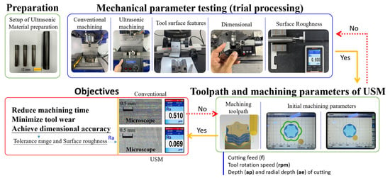
Precision machining of tungsten carbide (WC) presents challenges in surface quality, dimensional accuracy, and processing efficiency. This study developed an integrated computer numerical control (CNC) machining workflow combining ultrasonic-assisted machining (USM), stage-specific parameter allocation, and localized helical finishing. Conventional machining and USM were compared using DR14C, followed by machining parameter adjustments and toolpath optimization. The selected workflow was subsequently applied to TR15C and KG5. Under identical baseline conditions, USM reduced surface roughness from Ra 0.600 to 0.510 μm on the flat surface and from 0.617 to 0.504 μm in the groove, representing reductions of 15.0% and 18.3%, respectively. Confocal measurements further revealed reductions in mean Ra from 0.255 to 0.133 μm and mean Rz from 2.208 to 1.560 μm. The optimized process reduced CNC controller-simulated machining time by 82.7%. Localized helical finishing achieved Ra values of 0.352 and 0.429 μm on the flat and groove surfaces, respectively. Scanning electron microscopy (SEM), backscattered electron (BSE) imaging, and energy-dispersive X-ray spectroscopy (EDS) provided supplementary surface and elemental characterization. These findings demonstrated the effectiveness of the integrated workflow in improving machining quality and controller-predicted efficiency.
1. Introduction
1.1. Tungsten Carbide Overview
Tungsten carbide (WC)-based cemented carbides have been widely employed in cutting tools, precision molds, wear-resistant components, and advanced manufacturing systems owing to their high hardness, compressive strength, and wear resistance. The development of WC-based cemented carbides established an important foundation for the manufacturing of high-performance industrial components [1]. In conventional WC-Co cemented carbides, hard WC particles were distributed within a metallic cobalt (Co) binder, which contributed to densification, fracture toughness, and resistance to crack propagation [2]. The hardness and mechanical strength of these materials were strongly influenced by WC grain size, binder concentration, and microstructural characteristics [3]. The deformation and fracture behavior of WC-Co cemented carbides was associated with the mechanical interaction between hard carbide particles and the metallic binder [4]. The chemical composition and microstructural development of cemented carbides were influenced by binder selection, carbon content, and the incorporation of additional carbide phases [5,6]. Previous studies investigated the effects of carbide additives on phase formation and mechanical properties [7]. Changes in WC particle size and distribution were associated with variations in hardness, toughness, and microstructural uniformity [8]. Grain growth during sintering further affected the mechanical performance of cemented carbides [9], while carbide additives such as VC and Cr3C2 were investigated for controlling grain growth and microstructural development [10]. Despite these advantageous material properties, precision machining of WC-based cemented carbides presented significant challenges because of their high hardness, heterogeneous microstructure, and resistance to material removal. Tool wear, surface cracking, localized fracture, and dimensional deviations were important factors affecting machining quality. Zeng et al. [11] reviewed cutting and abrasive machining techniques for cemented carbide materials and identified tool selection, machining conditions, material characteristics, and surface integrity as principal factors influencing machining performance. These findings highlighted the importance of developing machining strategies that simultaneously considered surface quality, dimensional accuracy, and processing efficiency.
1.2. Conventional Machining and Ultrasonic Machining
Conventional machining methods for hard-to-machine materials have been investigated using different tool materials, machining configurations, and process parameters. Previous studies examined ultrasonic vibration-assisted high-speed milling and its influence on machining behavior under high-speed cutting conditions [12]. Diamond turning was also investigated for tungsten carbide components, with particular attention to dimensional accuracy and machined surface characteristics [13]. However, diamond-tool performance was influenced by thermochemical wear mechanisms under demanding cutting conditions [14]. Related studies on ultra-precision diamond turning further emphasized the importance of tool–workpiece interactions and machining conditions in determining surface quality [15]. Electrical discharge machining (EDM) was investigated as an alternative process for sintered tungsten carbide, where material removal was governed by localized electrical discharges and the resulting thermal effects [16]. Ultrasonic-assisted machining (USM) introduced high-frequency mechanical vibration into the machining process to modify the dynamic interaction between the tool and workpiece. Commercial ultrasonic machining systems were developed to integrate vibration-assisted toolholders with CNC machine tools [17]. Previous investigations of vibration-assisted micro-milling demonstrated the influence of high-frequency excitation on cutting characteristics and machining performance [18]. Recent studies have provided quantitative evidence of the effects of ultrasonic vibration on grinding performance and surface integrity. Ji et al. [19] investigated ultrasonic vibration-assisted grinding of high-velocity oxygen fuel (HVOF)-sprayed WC-10Co-4Cr coatings. Compared with conventional grinding, ultrasonic assistance reduced the normal grinding force by 22.23% and the tangential grinding force by 15.47%, while surface roughness decreased by 29.14%. These results demonstrated the relationship between ultrasonic vibration, grinding forces, and surface quality. Martins and Puga [20] reviewed ultrasonic-assisted milling applications and identified machining parameters, tool selection, vibration characteristics, and system integration as important factors affecting machining feasibility and performance. The reported findings indicated that ultrasonic assistance influenced machining performance through changes in tool–workpiece contact conditions, abrasive trajectories, and material removal behavior. The effectiveness of vibration assistance was associated with machining configuration, material characteristics, and process parameters. Consequently, the selection of suitable machining conditions remained important for achieving consistent surface quality and dimensional accuracy.
1.3. Machining Parameters and Toolpaths
Machining parameters and abrasive-tool characteristics played important roles in determining the surface integrity and processing efficiency of WC-based cemented carbides. Previous investigations of tungsten carbide grinding demonstrated the influence of machining conditions on material removal and surface formation [21]. Kataria et al. [22] investigated ultrasonic machining of WC-Co composites and evaluated the relationships among machining parameters and process responses. Further investigations using the Taguchi method examined the effects of ultrasonic machining parameters on the surface quality of WC-Co materials [23]. These studies established the importance of parameter selection in controlling machining performance. Abrasive characteristics and finishing strategies were also investigated for precision machining of cemented carbides. Feng et al. [24] examined ultra-precision grinding of WC-Ni hard metals, while Hsue and Zheng [25] investigated fine grinding of tungsten carbide using a flexible tool equipped with a rotary ultrasonic spindle. A #400 abrasive tool was employed during the initial grinding stage, followed by a #1000 abrasive tool with an approximate grain size of 13 μm for finishing. The use of different abrasive grades demonstrated the importance of distributing material removal and surface finishing across multiple machining stages. Guo and Zhao [26] investigated ultrasonic vibration-assisted grinding of hard and brittle microstructured surfaces and evaluated the effects of vibration trajectory and workpiece orientation on surface generation. More recent investigations further quantified the influence of machining configuration and finishing processes. Yavuzbarut et al. [27] investigated ultrasonic-assisted grinding of WC-25Co using a vibration frequency of 40 kHz and different tool orientations. Under the reported 45° grinding configuration, surface roughness decreased from Ra 0.86 to 0.33 μm, corresponding to a reduction of approximately 61.6%. Another grinding configuration produced a reduction from Ra 0.39 to 0.29 μm, representing an improvement of approximately 25.6%. Different surface responses were also observed during ultrasonic-assisted drilling, demonstrating the influence of machining direction and tool orientation on the resulting surface quality. Riu-Perdrix et al. [28] investigated the surface integrity of WC-Co cemented carbides subjected to different shaping and finishing processes. Surface roughness values of Ra 0.29 ± 0.01 μm and Ra 0.01 ± 0.01 μm were reported for ground and mechanically polished specimens, respectively. These results demonstrated the significant influence of finishing strategy on the achievable surface quality.
In addition to experimental surface characterization, grinding-force relationships were investigated through material removal rate, specific grinding energy, and grinding speed. Ren et al. [29] examined specific grinding energy in tungsten carbides with different grain sizes, establishing relationships between microstructural characteristics and grinding energy. Molaie et al. [30] investigated ultrasonic vibration-assisted grinding under different lubrication conditions, further demonstrating the importance of grinding-interface conditions in controlling machining performance. Recent investigations published between 2025 and 2026 provided additional quantitative evidence regarding ultrasonic vibration, grinding conditions, surface damage, and material removal mechanisms. Wen et al. [31] investigated ultrasonic vibration-assisted grinding of WC-10Co-4Cr coatings using a single diamond grain. The experiments employed an ultrasonic frequency of 20.6 kHz, a vibration amplitude of 6 μm, grinding speeds of 60–120 m/s, and a grinding depth of 20 μm. Ultrasonic assistance reduced the single-grain grinding force by 4.28–61% and decreased the reported subsurface damage depth from 37 to 31 μm. These findings demonstrated the relationship between vibration-assisted material removal, grinding-force reduction, and subsurface damage. Wen et al. [32] further investigated tangential ultrasonic vibration-assisted grinding of WC-10Co-4Cr coatings. Reductions of 5.05–14.04% in normal grinding force and 3.04–17.09% in tangential grinding force were reported. Surface roughness was reduced by 4.09–17.86%, and differences in grinding-force response were observed between grinding speeds of 20 and 80 m/s. The reported improvement ranges demonstrated the dependence of surface quality and grinding behavior on the selected machining conditions. Wu et al. [33] investigated laser pre-softening-assisted grinding of WC-Co cemented carbide. The selected grinding conditions consisted of a depth of cut of 5 μm, a workpiece feed rate of 20 mm/s, and a grinding speed of 39.58 m/s. Under the reported softening conditions, the normal and tangential grinding forces were reduced by approximately 50% and 45%, respectively, while a minimum areal surface roughness of Sa 0.136 μm was obtained. These results demonstrated the influence of material condition and grinding parameters on surface generation and grinding performance. Peng et al. [34] investigated the effects of machining parameters on surface integrity during creep-feed grinding of WC-Co cemented carbide. Surface roughness increased from Ra 0.507 to 0.595 μm with increasing grinding depth and from Ra 0.525 to 0.671 μm with increasing feed rate. In contrast, an increase in grinding wheel speed reduced Ra from 0.664 to 0.501 μm. The maximum subsurface crack depth increased from 2.06 to 6.33 μm with increasing grinding depth. Analysis of variance further identified feed rate as the principal factor affecting surface roughness, while grinding depth strongly influenced subsurface damage. Peng et al. [35] investigated surface integrity and material removal mechanisms during precision grinding of WC-Co cemented carbide using experimental characterization and multiscale analysis. The reported material removal behavior was associated with WC particle fracture, Co binder deformation, interfacial debonding, and brittle crack propagation. These findings demonstrated the relationship between microstructural characteristics, local material removal, and surface damage.
Recent developments in toolpath optimization further emphasized the importance of machining strategy in precision grinding. Gu et al. [36] developed an ultra-precision grinding and error-compensation strategy for WC-Co microstructured optical surfaces. The optimized machining process achieved a peak-to-valley surface form error below 200 nm and an areal surface roughness below Sa 15 nm. These results demonstrated the contribution of coordinated toolpath planning, grinding conditions, and error compensation to precision surface generation. The quantitative findings reported in recent studies demonstrated that machining performance was strongly influenced by material composition, grinding speed, feed rate, depth of cut, vibration characteristics, and finishing configuration. Different studies reported performance through surface roughness, grinding forces, subsurface damage, and dimensional accuracy. The investigated materials also differed between bulk WC-Co cemented carbides and WC-based coatings, resulting in different material removal conditions and surface responses. These differences highlighted the importance of evaluating machining performance under clearly defined experimental conditions. Furthermore, processing efficiency was associated with toolpath length, machining allowance, material removal distribution, and the selected finishing strategy. Although recent studies demonstrated improvements in grinding forces and surface quality, the reported results varied considerably with material composition, machining configuration, vibration direction, and selected process parameters. Ji et al. [19] and Wen et al. [31,32] investigated WC-based coatings, whereas Wu et al. [33], Peng et al. [34,35], and Gu et al. [36] focused on bulk WC-Co cemented carbides. These differences in material systems influenced the corresponding removal mechanisms and surface responses. Furthermore, surface roughness was evaluated using different indicators, including Ra and Sa, while processing performance was characterized through grinding forces, subsurface damage, and geometric accuracy. The reported findings emphasized the importance of evaluating machining parameters and finishing strategies within clearly defined experimental configurations. Accordingly, the present study integrated ultrasonic assistance, staged machining-parameter allocation, and localized helical finishing to investigate surface quality, dimensional accuracy, and controller-simulated machining efficiency in three commercial tungsten carbide grades.
1.4. Research Objectives and Contributions
Previous studies established the importance of ultrasonic vibration, machining parameters, abrasive characteristics, and material removal mechanisms in determining the surface integrity of WC-based materials [19,22,27,31,32,33,34,35,36]. Recent investigations further demonstrated the influence of grinding speed, feed rate, cutting depth, vibration direction, and toolpath planning on machining quality. Building upon these findings, the present study focused on integrating ultrasonic assistance, stage-specific machining parameter allocation, and localized helical finishing within a three-axis computer numerical control (CNC) machining system. The primary objective was to develop and evaluate an integrated machining workflow for precision tungsten carbide components. Three commercial WC grades, DR14C, TR15C, and KG5, were selected to investigate machining performance across different material characteristics. Conventional machining and USM were initially compared under identical programmed conditions to evaluate surface roughness, dimensional accuracy, and diamond-point surface condition. Subsequently, feed rate, radial depth of cut, and machining allowance were adjusted for roughing, semi-finishing, and finishing operations. Full-profile and localized helical finishing strategies were compared to investigate the effects of finishing-toolpath configuration on the resulting surface quality. The machining performance was evaluated through dimensional measurements, surface roughness, confocal surface topography, and CNC controller-simulated machining time. Scanning electron microscopy (SEM), backscattered electron (BSE) imaging, and energy-dispersive X-ray spectroscopy (EDS) were additionally employed to characterize surface morphology, microstructural contrast, and elemental compositions. The principal contribution of this study was the coordinated implementation of ultrasonic assistance, stage-specific machining parameters, and localized helical finishing within a practical CNC machining workflow. The controlled baseline comparison quantified the surface-quality response associated with ultrasonic assistance, while subsequent machining stages evaluated the combined effects of parameter adjustment and finishing-toolpath selection. The application of the selected machining conditions to three WC grades further provided comparative experimental data for materials with different nominal binder contents and mechanical properties. This integrated approach provided a systematic framework for evaluating precision machining quality and controller-predicted processing efficiency in WC-based components.
2. Materials and Methods
A staged machining study was conducted using a USM system integrated into a three-axis CNC machining center. Conventional machining and USM were first compared under identical baseline conditions using DR14C WC. Machining parameters were then adjusted for roughing, semi-finishing, and finishing, followed by a comparison of finishing toolpaths. The selected conditions were subsequently applied to TR15C and KG5. Diamond point condition, dimensional error, surface roughness, and CNC controller-simulated machining time were evaluated. The experimental design, equipment, materials, machining conditions, and measurement methods are described in the following sections.
2.1. Experimental Design and Baseline Machining Conditions
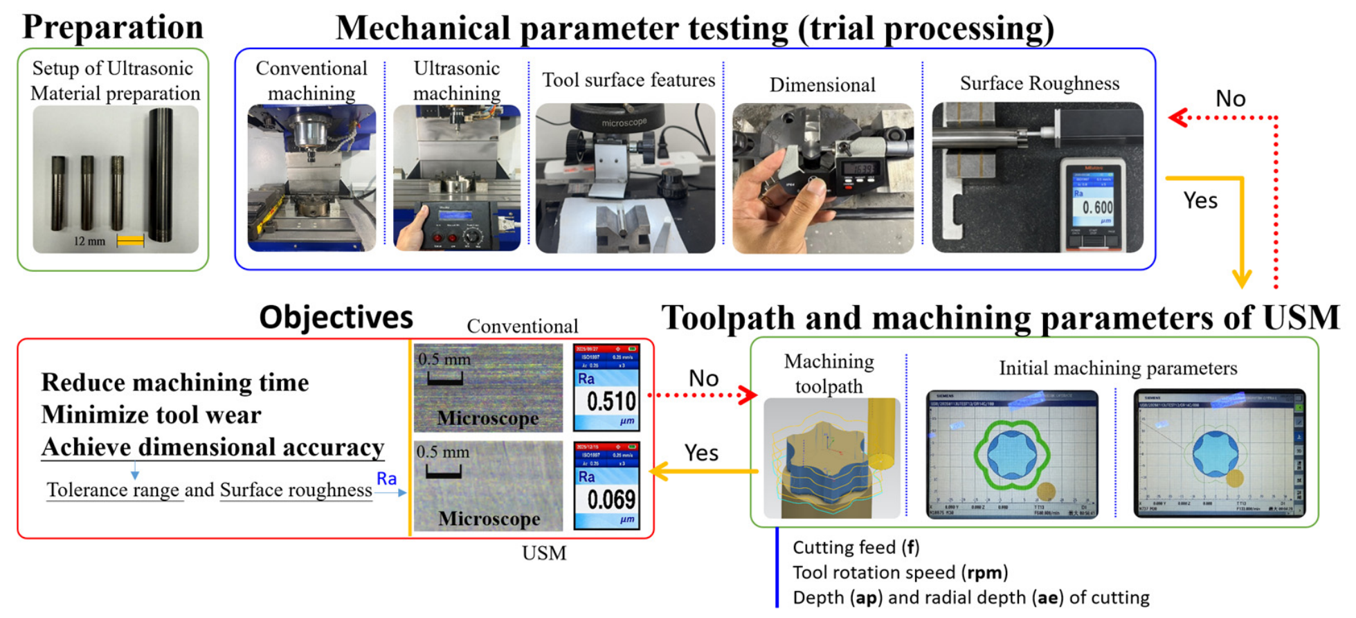
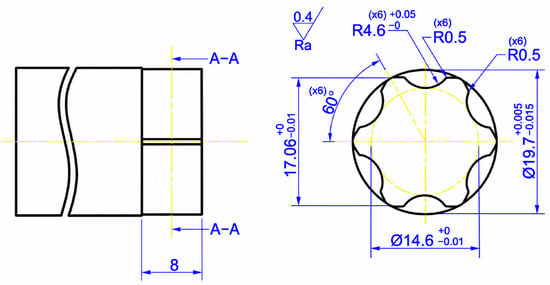
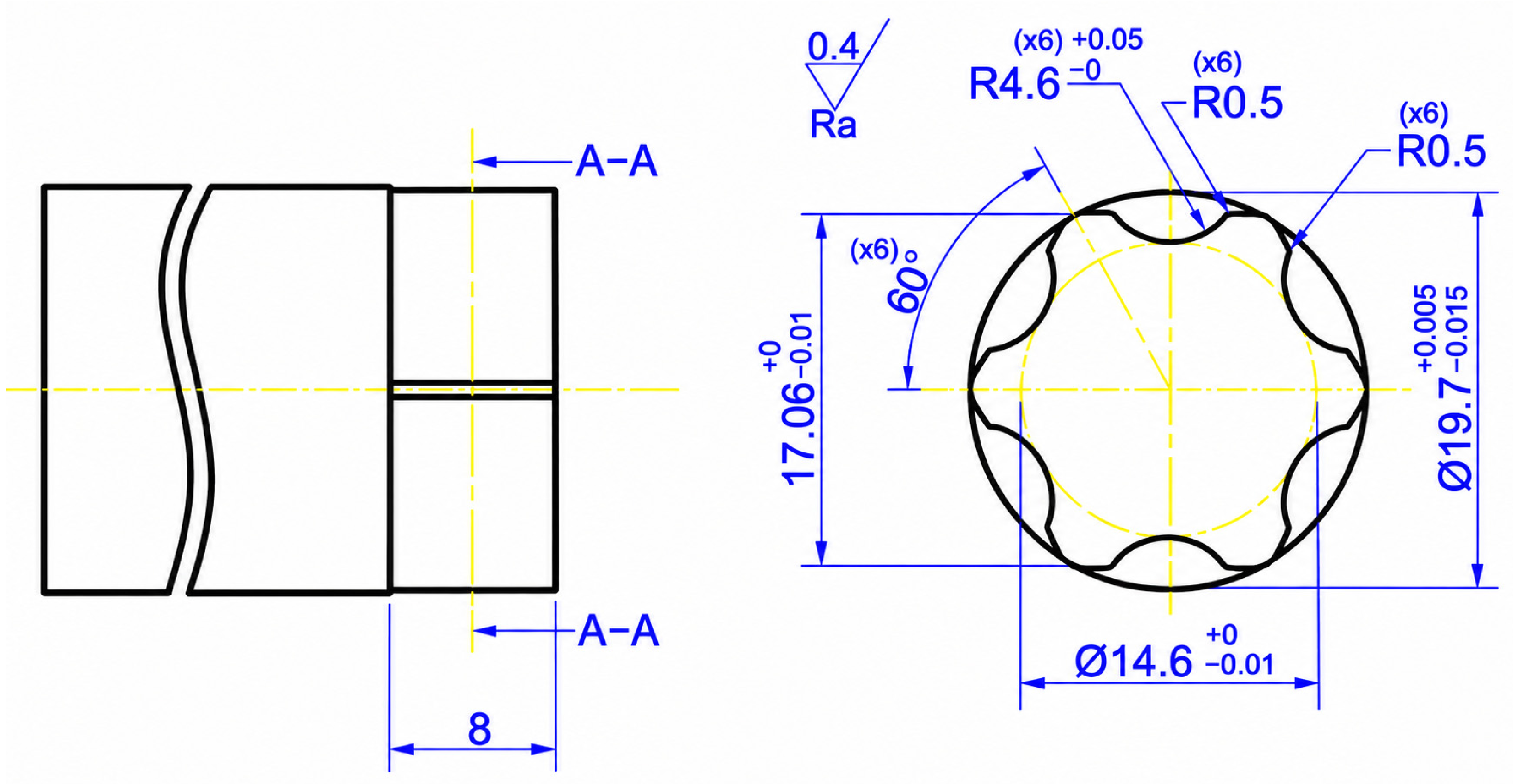
A USM system was integrated into a three-axis CNC machine tool. Staged machining experiments were performed on three WC grades: DR14C, TR15C, and KG5. Diamond points with grit sizes of #100, #400, and #800 were assigned to roughing, semi-finishing, and finishing, respectively. The experimental sequence is shown in Figure 1. Specimen geometry and machining features were defined by the manufacturing drawing shown in Figure 2.
Figure 1.
Experimental Procedure.
Figure 2.
Manufacturing Drawing.
DR14C was used for the initial comparison. Conventional machining and USM were performed under identical spindle-speed, feed-rate, depth-of-cut, machining-allowance, and coolant-delivery conditions. One independently machined workpiece was evaluated for each tested machining condition. For each workpiece, the #100, #400, and #800 machining operations were conducted sequentially as the roughing, semi-finishing, and finishing stages, respectively. The dimensional values recorded at locations A1–A6 were obtained from six specified locations on the same workpiece and therefore represent within-workpiece spatial measurements rather than six independent machining replicates. Similarly, the surface-roughness measurements and confocal profile lines were obtained from the corresponding machined surface rather than from independently machined specimens. Because no independently repeated machining trials were performed, the experimental sample size was n = 1 workpiece per condition. Dimensional error, surface roughness, and diamond-point surface condition, including qualitative WC-powder adhesion, were evaluated during the initial comparison. Feed rate, depth of cut, and machining allowance were subsequently adjusted for each machining stage. Side-finishing and helical plunge-finishing toolpaths were then examined. The selected process conditions were subsequently applied to TR15C and KG5, and the machining responses of the three WC grades were compared. Controller-predicted machining times were obtained from the Siemens 840D controller (Siemens AG, Erlangen, Germany) simulation and were used to compare the programmed process. conditions. A semi-synthetic water-soluble cutting fluid (LW-611EP, SLUBE, Da-Jin Lubricants Co., Ltd., Tainan, Taiwan) was used throughout the machining experiments. The coolant concentrate contains refined mineral oil and extreme-pressure additives. The coolant was prepared at a water-to-concentrate ratio of 20:1, corresponding to an approximate concentrate volume fraction of 4.76 vol.%. This dilution ratio was within the manufacturer-recommended range of 20:1–40:1. The machining center was operated using its external flood-coolant system, and the coolant was continuously supplied through adjustable external nozzles directed toward the tool–workpiece contact region. The same coolant product, dilution ratio, nozzle arrangement, pump setting, and valve setting were maintained throughout the conventional, ultrasonic, parameter-adjustment, and finishing-toolpath experiments. However, the nozzle supply pressure and total coolant flow rate were not instrumented during the experiments. In Table 1, “Flood” refers to the continuous external supply of the SLUBE LW-611EP coolant described above. The baseline machining parameters are listed in Table 1.
Table 1.
Machining Parameters.
2.2. Experimental Equipment and Machining System
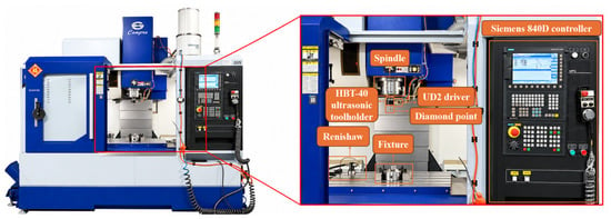
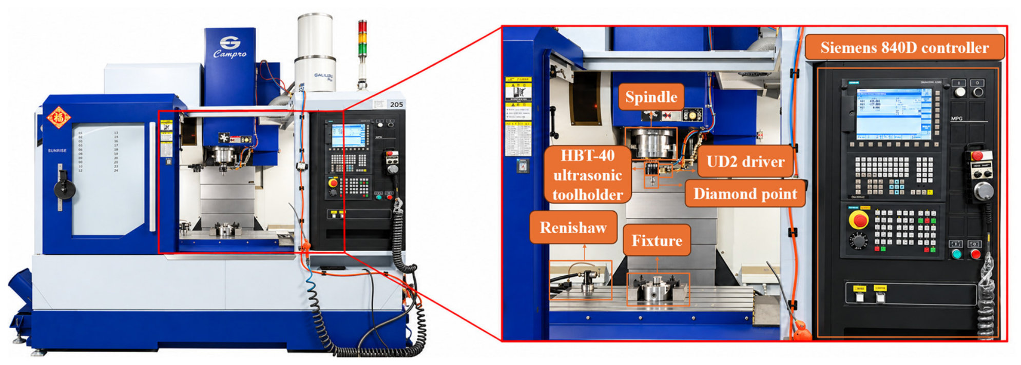
A CAMPRO CNV-850 vertical machining center equipped with a Siemens 840D controller was used for the machining experiments. Travels of 850, 520, and 520 mm were provided along the X, Y, and Z axes, respectively. A maximum spindle speed of 10,000 rpm and a BT-40 tool interface were specified for the machining center. The machining center was photographed, as presented in Figure 3. Its main specifications are listed in Table 2.
Figure 3.
CAMPRO CNV-850 vertical machining center.
Table 2.
Specifications of the CAMPRO CNV-850 vertical machining center.
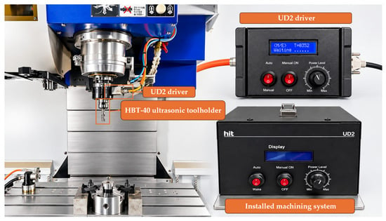
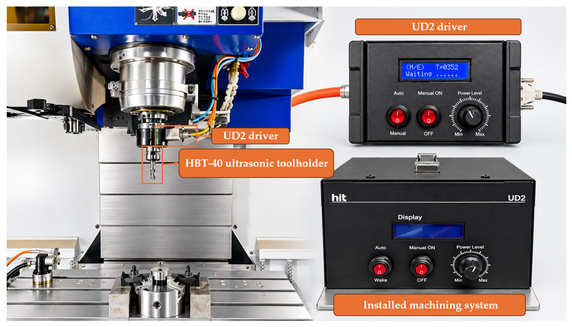
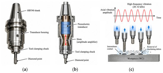
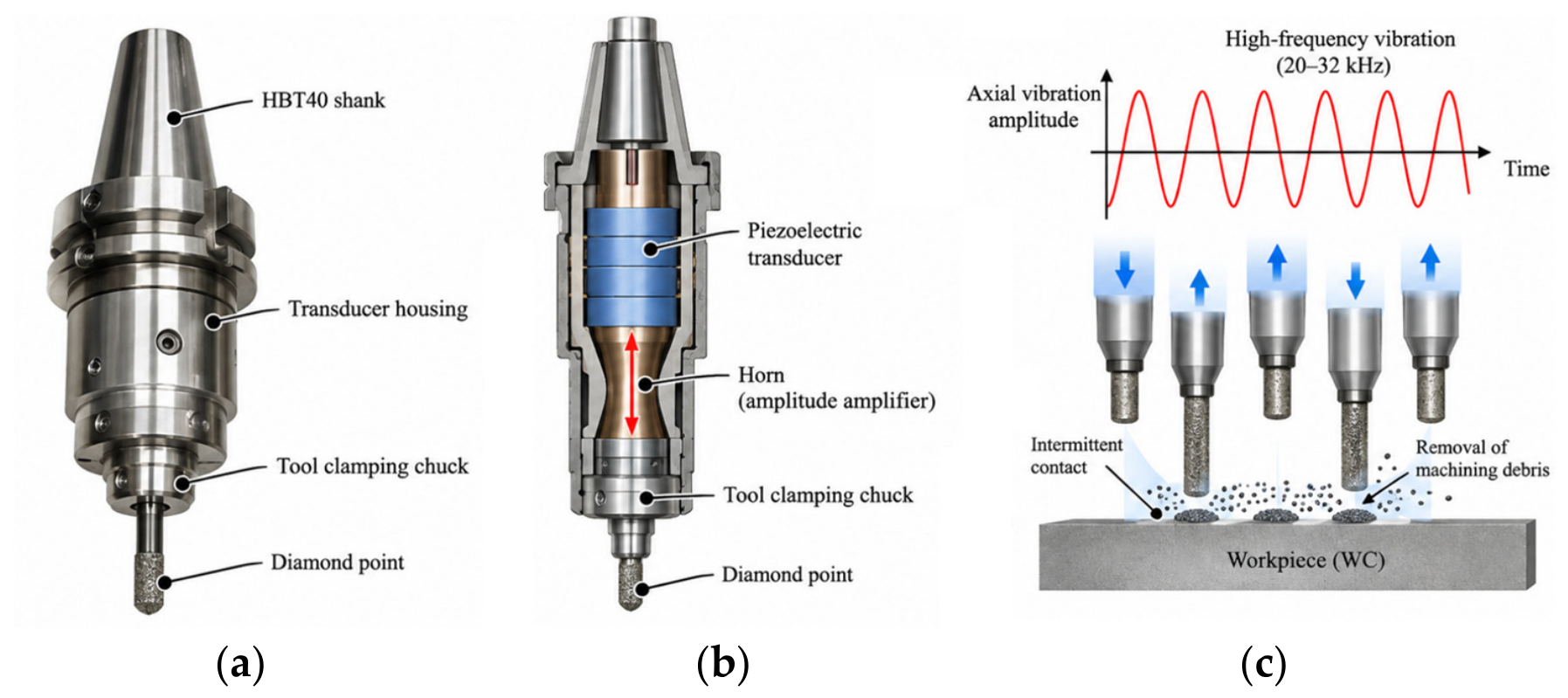
An ultrasonic machining system consisting of a UD2 driver (Hantop Intelligence Technology Co., Ltd., Taichung, Taiwan) and an HBT-40 ultrasonic toolholder (Hantop Intelligence Technology Co., Ltd., Taichung, Taiwan) was installed on the machining center. A frequency range of 14–56 kHz and a maximum power of 60 W were specified for the UD2 driver. An operating frequency of 20–32 kHz and a tool runout below 5 μm were specified for the HBT-40 toolholder. The system components and their installation are presented in Figure 4, and their specifications are listed in Table 3 and Table 4. The structure and operating principle of the ultrasonic toolholder are illustrated in Figure 5. Electrical energy supplied by the ultrasonic driver was converted into high-frequency mechanical vibration by the piezoelectric transducer inside the toolholder. The generated vibration was transmitted through the horn and was delivered to the diamond point along the axial direction. During machining, axial ultrasonic vibration at an operating frequency of approximately 24.66 kHz, as indicated by the UD2 driver, was superimposed on the rotational and feed motions of the tool. Periodic contact and separation between the diamond point and the WC workpiece were therefore expected to occur. The resulting intermittent tool–workpiece contact may have reduced continuous mechanical contact and friction at the machining interface and promoted the removal of machining debris and WC powder from the machining region.
Figure 4.
Ultrasonic machining system, including the HBT-40 ultrasonic toolholder, UD2 driver, and installed machining system.
Table 3.
Specifications of the UD2 ultrasonic driver.
Table 4.
Specifications of the HBT-40 ultrasonic toolholder.
Figure 5.
Structure and operating principle of the ultrasonic toolholder: (a) HBT-40 ultrasonic toolholder; (b) internal structure and vibration transmission; (c) working principle of ultrasonic machining with axial high-frequency vibration.
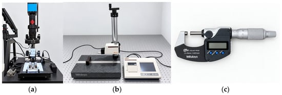
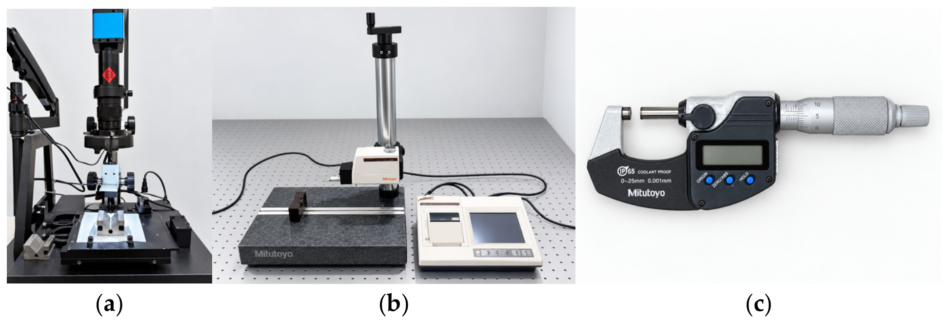
Machined surfaces were measured using a surface roughness tester. Diamond point surfaces and powder adhesion were examined using an industrial microscope. Workpiece dimensions were measured using an outside micrometer with a measurement range of 0–25 mm and a resolution of 0.001 mm. The inspection instruments are documented in Figure 6. Their main specifications are listed in Table 5, Table 6 and Table 7.
Figure 6.
Inspection instruments: (a) surface roughness tester; (b) industrial microscope; (c) outside micrometer.
Table 5.
Specifications of the surface roughness tester.
Table 6.
Specifications of the industrial microscope.
Table 7.
Specifications of the outside micrometer.
Additional surface-topography measurements were performed by an external testing laboratory using a VK-X1000-series three-dimensional laser scanning confocal microscope (KEYENCE Corporation, Osaka, Japan). The system employs a pinhole confocal optical system and focus-variation measurement with a 16-bit photomultiplier and a high-definition color CMOS sensor (VK-X1000 system) (KEYENCE Corporation, Osaka, Japan). According to the manufacturer, the system provides a total magnification of up to 28,800× and a field-of-view range from 11 to 7398 μm. Additional microscopic characterization was performed using a scanning electron microscope (SEM; S-3400, Hitachi High-Technologies Corporation, Tokyo, Japan) equipped with a backscattered electron (BSE) detector (Hitachi High-Technologies Corporation, Tokyo, Japan) and an energy-dispersive X-ray spectroscopy (EDS) system (HORIBA, Ltd., Kyoto, Japan). The SEM and BSE imaging techniques were employed to examine the machined surface morphology and microstructural contrast of the tungsten carbide specimens. EDS analysis was conducted to characterize the elemental compositions of DR14C, TR15C, and KG5.
2.3. Workpiece Materials and Cutting Tools
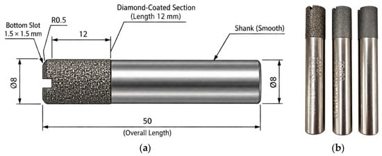
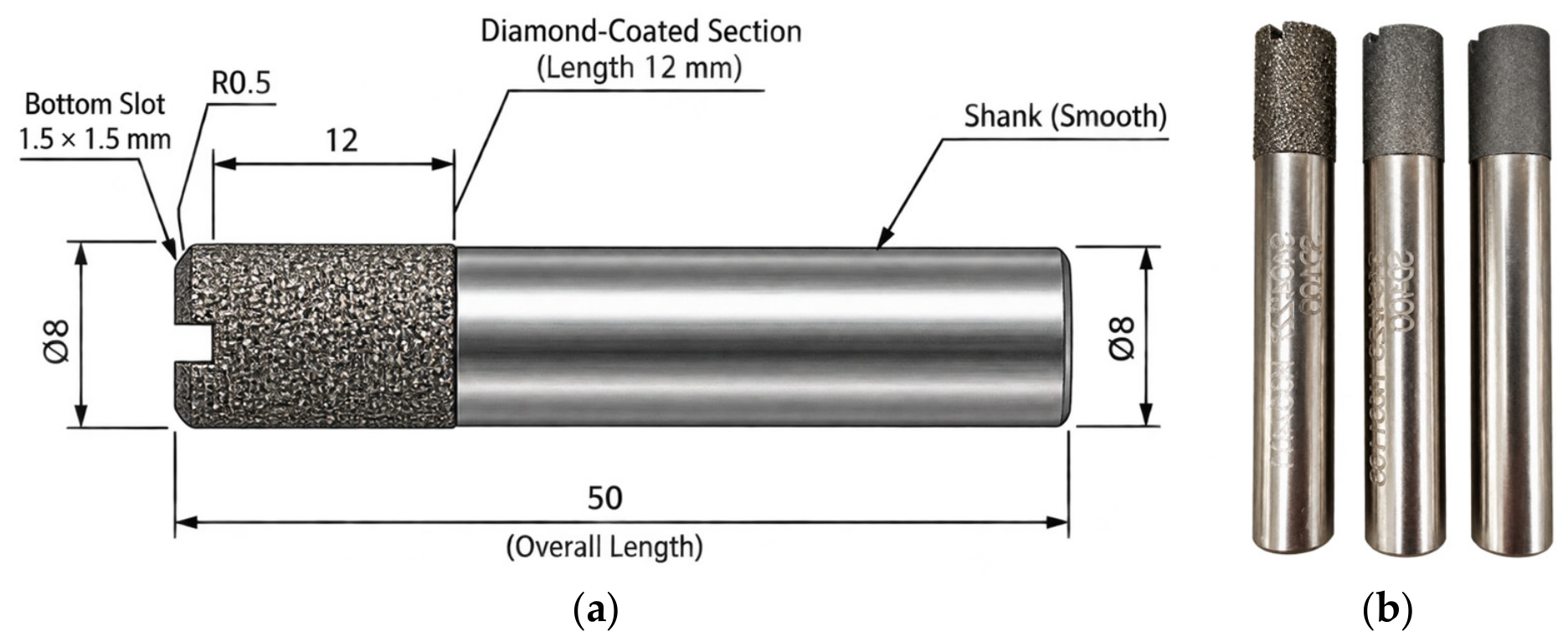
Three tungsten carbide (WC) grades supplied by the industrial partner were used as workpiece materials: DR14C and TR15C manufactured by NotoAlloy (NOTOALLOY Co., Ltd., Shika, Ishikawa, Japan), and KG5 manufactured by CB-CERATIZIT (CB-CERATIZIT Taiwan Co., Ltd., New Taipei City, Taiwan). Each cylindrical workpiece was prepared with a diameter of 20 mm. According to the nominal manufacturer-supplied compositions, the Co binder contents of DR14C, TR15C, and KG5 were 14, 15, and 12 wt.%, respectively. The corresponding remaining fractions, consisting of WC and additives, were 86, 85, and 88 wt.%, respectively, as summarized in Table 8. The specific gravities of DR14C, TR15C, and KG5 were 14.10, 14.00, and 14.31 g/cm3, respectively, while their corresponding hardness values were 89.00, 87.00, and 88.30 HRA. The fracture toughness values were 20, 29, and 17 MPa ⋅ m1/2, respectively. DR14C and TR15C were classified as fine-grained cemented carbides, whereas KG5 was classified as a medium-grained cemented carbide. Diamond points manufactured by Taiwan Asahi Diamond Industrial Co., Ltd. (Taoyuan, Taiwan) were used as the machining tools. Nominal abrasive grit sizes of #100, #400, and #800 were selected for roughing, semi-finishing, and finishing, respectively. Each diamond point had a nominal diameter of 8 mm and a tip radius of 0.5 mm. The geometry and appearance of the three diamond points are presented in Figure 7.
Table 8.
Nominal chemical compositions and properties of the tungsten carbide workpieces.
Figure 7.
Diamond points used in the machining experiments: (a) tool geometry; (b) diamond points with grit sizes of #100, #400, and #800.
2.4. Adjustment of Machining Parameters
Machining parameters were adjusted in the second experimental stage based on the comparison between conventional machining and ultrasonic machining. Feed rate, axial depth of cut, radial depth of cut, and machining allowance were assigned to the roughing, semi-finishing, and finishing stages, as listed in Table 9. Dimensional errors and surface roughness were evaluated after each adjustment. Machining times for the baseline and adjusted conditions were obtained from the CNC controller simulation and compared.
Table 9.
Adjusted machining parameters for each machining stage.
2.5. Helical Toolpath Design and Finishing Strategies
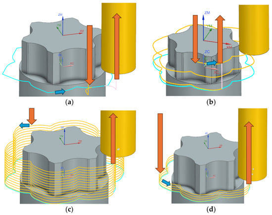
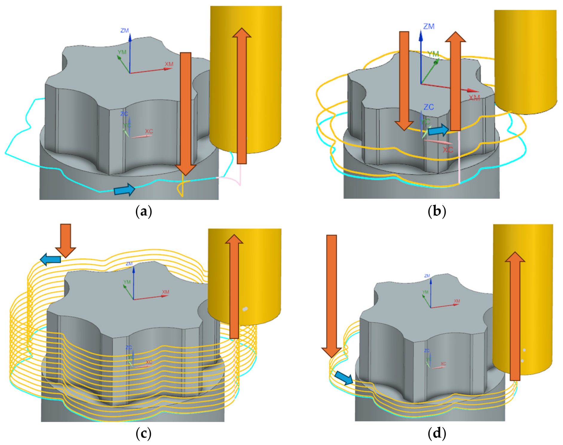
Finishing toolpaths were adjusted after the machining parameters were selected. Conventional side-finishing and helical plunge-finishing were initially compared, as illustrated in Figure 8a,b. Based on the preliminary comparison, two helical plunge-finishing strategies were further evaluated. Full-profile helical finishing was initiated at an actual Z-coordinate of 0 mm, and the complete workpiece profile was machined (Figure 8c). In contrast, localized helical finishing was initiated at an actual Z-coordinate of −6 mm and was restricted to the local finishing region (Figure 8d). The corresponding machining parameters are listed in Table 10 and Table 11. Dimensional error and surface roughness were compared to evaluate the performance of both finishing strategies.
Figure 8.
Finishing toolpaths and helical plunge-finishing strategies: (a) side-finishing; (b) helical plunge-finishing; (c) full-profile helical finishing; and (d) localized helical finishing.
Table 10.
Machining parameters for full-profile helical finishing.
Table 11.
Machining parameters for localized helical finishing.
2.6. Measurement and Performance Evaluation
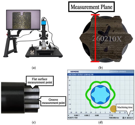
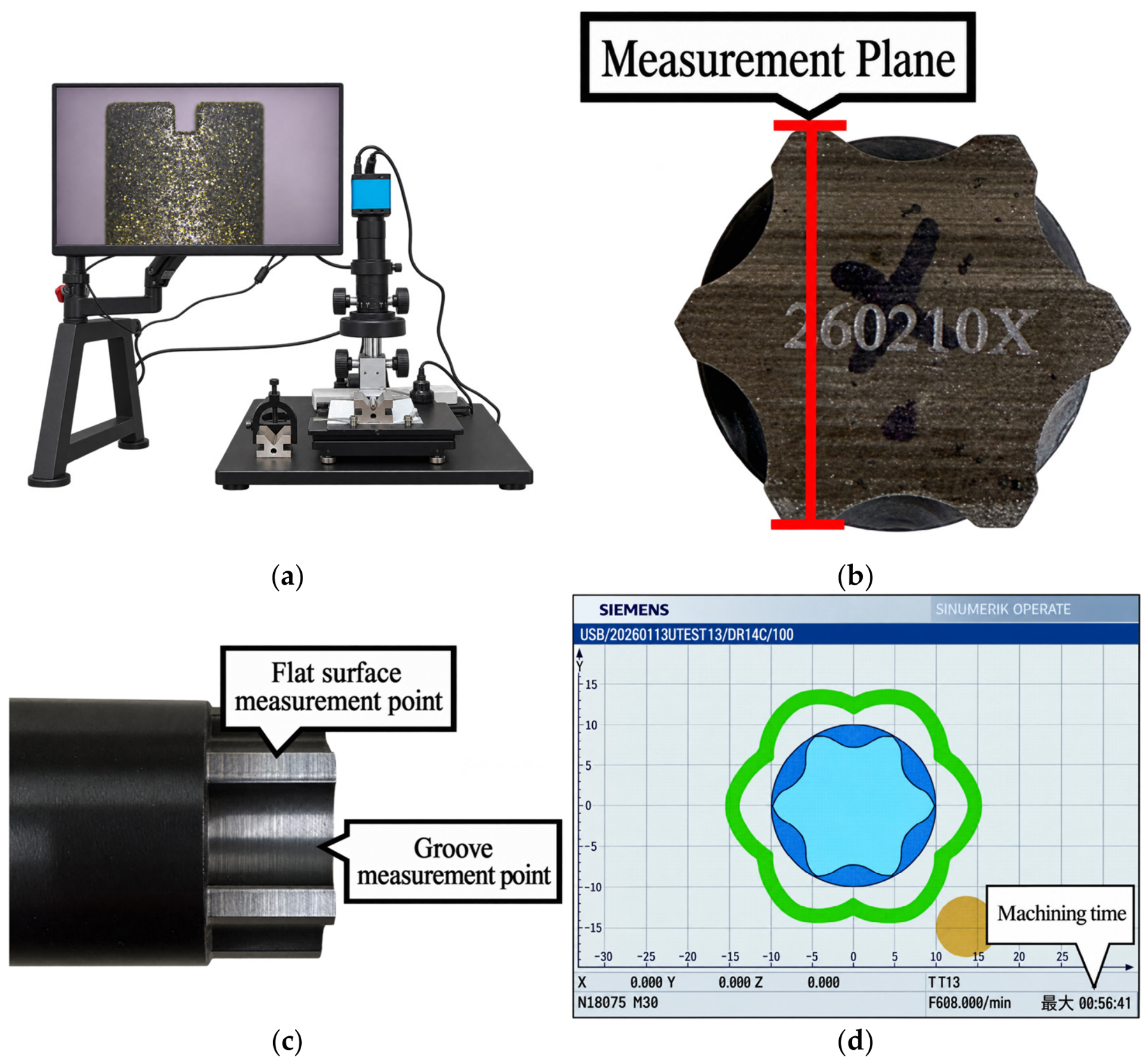
Diamond-point surfaces were examined using an industrial microscope to assess the condition of the diamond coating and the adhesion of WC powder. The microscope setup used for the inspection is shown in Figure 9a. Dimensions at six specified workpiece surfaces were measured using an outside micrometer, and the corresponding measurement plane is presented in Figure 9b. Dimensional error was calculated as the difference between each measured dimension and its nominal value. Surface roughness was measured using a surface roughness tester. One measurement location on the flat surface and one location in the groove were selected for each measurement, as shown in Figure 9c. Toolpaths were simulated using the Siemens 840D controller, and the simulation interface is presented in Figure 9d. The CNC-controller-predicted machining times were recorded for the baseline and adjusted process plans. These values represent simulated program-execution times rather than experimentally measured machining cycle times. The time comparison was therefore interpreted only as an estimate of the effect of the combined process-plan changes.
Figure 9.
Measurement and performance-evaluation procedures: (a) industrial microscope setup used to inspect the diamond-point surface; (b) workpiece measurement plane used for dimensional evaluation; (c) surface-roughness measurement locations on the flat surface and in the groove; and (d) Siemens 840D controller interface used for machining-time simulation.
To characterize the nominal mechanical loading associated with the three abrasive grit stages, an energy-based grinding-force formulation was adopted based on established relationships among grinding power, specific grinding energy, material removal rate, wheel speed, and tangential grinding force [29,30]. The formulation was applied to the baseline machining conditions listed in Table 1. The calculation was based on the diamond-point diameter, spindle speed, feed rate, axial engagement depth, and radial depth of cut. The programmed machining allowance was not included in the calculation because it represents the residual stock assigned to a machining stage rather than the instantaneous radial depth of cut. For each abrasive grit stage j, the peripheral speed of the diamond point was calculated as
where Dj is the diamond-point diameter in mm and nj is the spindle speed in rpm. The nominal feed per revolution was calculated as
where Vf,j is the feed rate in mm/min. The nominal material-removal cross-sectional area was calculated as
where ap,j and ae,j are the axial engagement depth and radial depth of cut, respectively. The volumetric material removal rate was calculated as
The grinding power was related to the volumetric material removal rate through the specific grinding energy [29,30]
where m denotes conventional machining or ultrasonic-assisted machining, and uj,m is the specific grinding energy in J/mm3. A separate specific grinding energy uj,m was retained for each abrasive-grit stage and machining mode because the specific grinding energy of WC depends on material properties, abrasive-workpiece interactions, and grinding conditions [29]. Because grinding power is equal to the product of tangential grinding force and peripheral speed [30], the nominal tangential grinding-force relationship was expressed as
Because neither spindle grinding power nor condition-specific grinding energy was experimentally determined, Equation (6) was used to establish nominal force relationships rather than absolute cutting-force values.
For supplementary surface-topography evaluation, the surfaces machined with and without ultrasonic vibration were measured by an external testing laboratory using a VK-X1000-series three-dimensional laser scanning confocal microscope (KEYENCE Corporation, Osaka, Japan). The nominal measurement area was approximately 280 × 220 μm. Multiple parallel profile lines perpendicular to the machining marks were evaluated. The instrument software provided two-dimensional surface images, three-dimensional topography maps, and summary statistics for Ra, Rz, and RSm, including the mean, maximum, minimum, and standard deviation. The surfaces machined with and without ultrasonic vibration were evaluated using the same reported analysis procedure. Additional surface characterization was performed using scanning electron microscopy (SEM), backscattered electron (BSE) imaging, and energy-dispersive X-ray spectroscopy (EDS). SEM and BSE observations were conducted on the machined tungsten carbide specimens at magnifications of 1000× and 4000×, respectively. The observed regions were selected according to the machining conditions, finishing strategies, and surface locations investigated in this study. EDS measurements were performed to determine the normalized elemental concentrations of C, Co, W, and the additionally detected Cr in the analyzed regions. The corresponding characterization results are presented in Section 3.5 and Section 3.6.
3. Results and Discussion
3.1. Comparison of Conventional and Ultrasonic Machining
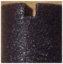
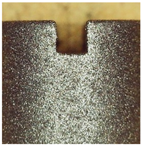
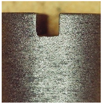
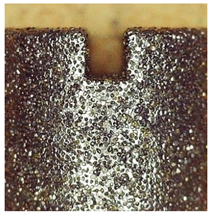
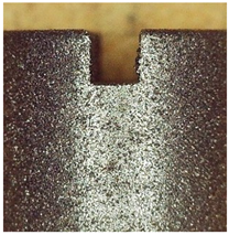
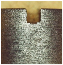
Qualitative microscopic inspection revealed visibly lower WC-powder accumulation on the diamond-point surfaces after ultrasonic machining than after conventional machining, as shown in Table 12. Because no calibrated image-segmentation or deposited-area analysis was performed, the tool-surface images were used for qualitative comparison, and no exact percentage reduction was assigned. The lower powder accumulation is consistent with improved debris evacuation under ultrasonic vibration. Periodic tool–workpiece contact and separation may reduce continuous interfacial friction and facilitate the entry of cutting fluid into the machining region. The driver-indicated ultrasonic operating frequency remained approximately 24.66 kHz during the monitored machining operations, suggesting that the ultrasonic system operated under a similar frequency condition for the three diamond-point assemblies.
Table 12.
Qualitative comparison of the diamond-point surface condition after conventional and ultrasonic machining.
Based on the baseline machining parameters listed in Table 1, the peripheral speed of the 8 mm diameter diamond points at 8000 rpm was 3.351 m/s. Because a feed rate of 200 mm/min was used for all three abrasive grit stages, the nominal feed per revolution was 0.025 mm/rev. For the #100 roughing stage, an axial engagement depth of 8 mm and a radial depth of cut of 0.015 mm produced a nominal material-removal cross-sectional area of 0.120 mm2 and a volumetric material removal rate of 0.4000 mm3/s. Substitution of these values into Equation (6) gave the following nominal tangential-force relationship:
For the #400 semi-finishing stage, an axial engagement depth of 8 mm and a radial depth of cut of 0.005 mm produced a nominal material-removal cross-sectional area of 0.040 mm2 and a volumetric material removal rate of 0.1333 mm3/s. The corresponding force relationship was
The #800 finishing stage was conducted using the same spindle speed, feed rate, axial engagement depth, and radial depth of cut as the #400 stage. Therefore, its nominal material-removal cross-sectional area and volumetric material removal rate were also 0.040 mm2 and 0.1333 mm3/s, respectively. However, the force relationship was expressed using a separate condition-specific grinding energy because the finer abrasive grit may produce different rubbing, ploughing, and effective grain-contact characteristics:
The nominal force coefficient for the #100 stage was three times that obtained for the #400 and #800 stages because of its larger radial depth of cut under the baseline conditions. In addition, because conventional machining and USM were conducted using identical kinematic parameters, any difference between their actual cutting forces would have to be reflected in the condition-specific grinding energy or measured spindle power.
Dimensional measurements obtained after conventional machining and USM were listed in Table 13 and Table 14, respectively. For the baseline comparison, the drawing sizes corresponding to the #100, #400, and #800 machining stages were 17.32, 17.11, and 17.06 mm, respectively. These dimensions represented the staged removal of the reserved machining allowance from roughing to semi-finishing and finally to the target finishing dimension of 17.06 mm. The effect of USM on dimensional accuracy varied with abrasive grit size. Dimensional accuracy improved by approximately 18.4% for #100 and 50.0% for #800, while a slight decrease of approximately 2.6% was observed for #400. Surface roughness measured using the contact surface roughness tester decreased from Ra 0.600 to 0.510 μm on the flat surface, corresponding to a reduction of 15.0%. In the groove, Ra decreased from 0.617 to 0.504 μm, corresponding to a reduction of 18.3%. Thus, the effect of ultrasonic vibration depended on the machining stage and evaluation parameter: improvements were observed in surface roughness and in the dimensional errors after the #100 and #800 stages, whereas no improvement in dimensional error was obtained after the #400 stage.
Table 13.
Dimensional measurements and errors after conventional machining.
Table 14.
Dimensional measurements and errors after USM.
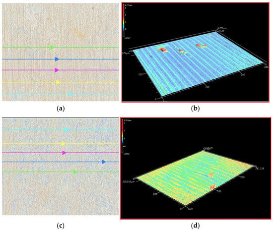
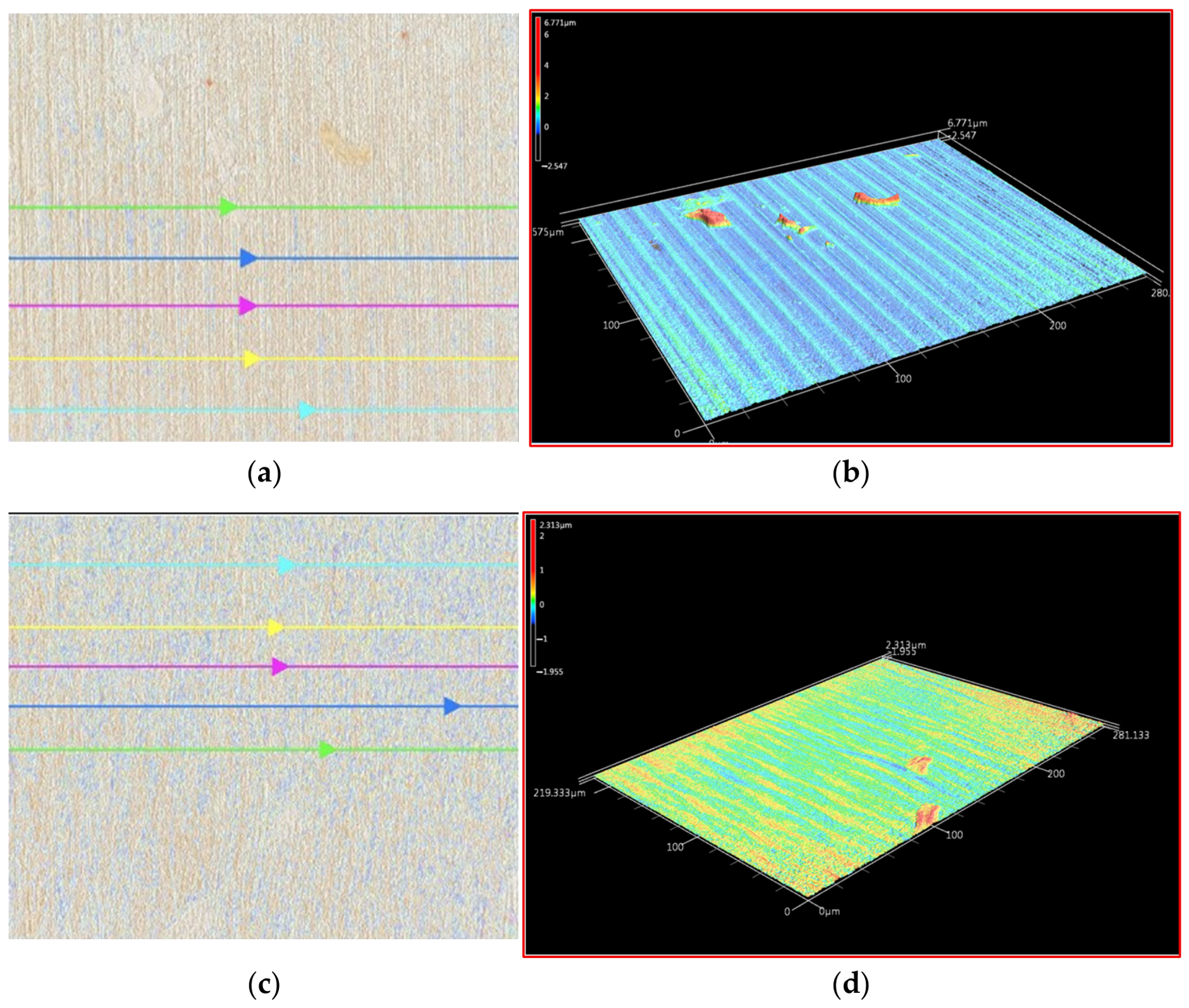
Surface topography was further evaluated using a VK-X1000-series three-dimensional laser scanning confocal microscope. The resulting two-dimensional and three-dimensional surface maps are presented in Figure 10, and the profile parameters are summarized in Table 15. Without ultrasonic vibration, the surface exhibited more pronounced parallel machining marks and greater profile-height variation. With ultrasonic vibration, the profile-averaged Ra decreased from 0.255 ± 0.019 to 0.133 ± 0.004 μm, corresponding to a reduction of 47.8%. Similarly, Rz decreased from 2.208 ± 0.086 to 1.560 ± 0.239 μm, representing a reduction of 29.3%. RSm increased from 16.524 ± 1.904 μm without ultrasonic vibration to 17.884 ± 1.490 μm with ultrasonic vibration. This increase indicates a change in the mean spacing of the profile elements and should not be interpreted directly as either an improvement or deterioration in surface roughness. Without ultrasonic vibration, Ra ranged from 0.232 to 0.284 μm, Rz ranged from 2.101 to 2.289 μm, and RSm ranged from 15.081 to 20.269 μm. With ultrasonic vibration, the corresponding ranges were 0.129–0.141 μm for Ra, 1.359–2.022 μm for Rz, and 16.121–20.603 μm for RSm.
Figure 10.
Confocal surface characterization of DR14C WC after #800 finishing using a KEYENCE VK-X1000 series three-dimensional laser scanning confocal microscope: (a) two-dimensional surface image and profile-measurement lines without ultrasonic vibration; (b) corresponding three-dimensional surface topography without ultrasonic vibration; (c) two-dimensional surface image and profile-measurement lines with ultrasonic vibration; and (d) corresponding three-dimensional surface topography with ultrasonic vibration. The nominal measurement area was approximately 280 × 220 μm. Different height-scale limits were retained in (b,d) for visualization; therefore, the surface colors should not be compared directly. Quantitative comparisons were based on the extracted Ra, Rz, and RSm values.
Table 15.
Confocal profile parameters of surfaces machined with and without ultrasonic vibration.
In the displayed three-dimensional topographies, the height scale extended from −2.547 to 6.771 μm without ultrasonic vibration and from −1.955 to 2.313 μm with ultrasonic vibration, corresponding to displayed height spans of 9.318 and 4.268 μm, respectively. However, isolated particles produced local height peaks, and the two maps were originally exported using different height scales. Therefore, these displayed height spans were treated as supporting qualitative observations and were not interpreted as standardized Sz values. The lower Ra and Rz values are consistent with a reduction in the amplitude of the residual machining marks. Periodic tool–workpiece separation under ultrasonic vibration may reduce continuous abrasive ploughing and the re-cutting of detached WC particles, thereby producing shallower machining marks. Nevertheless, this mechanism was inferred from the surface-topography results and was not directly verified through cutting-force or debris-flow measurements. The absolute Ra values obtained by confocal microscopy should not be directly compared with those obtained using the contact surface roughness tester because the two methods used different measurement principles, evaluation areas, profile lengths, and filtering procedures. The confocal results were therefore used as supplementary comparative evidence between the ultrasonic and non-ultrasonic conditions. Furthermore, confocal microscopy characterizes surface geometry only and does not provide evidence regarding crystallographic phase transformation, subsurface deformation, or microstructural damage. Overall, under the tested conditions, USM was associated with lower WC-powder accumulation on the diamond points, lower surface roughness, and reduced dimensional errors after the #100 and #800 machining stages. No dimensional improvement was observed after the #400 stage. These results were subsequently used to guide the adjustment of machining parameters and finishing toolpaths.
3.2. Effect of Machining Parameter Adjustment on Controller-Simulated Machining Time
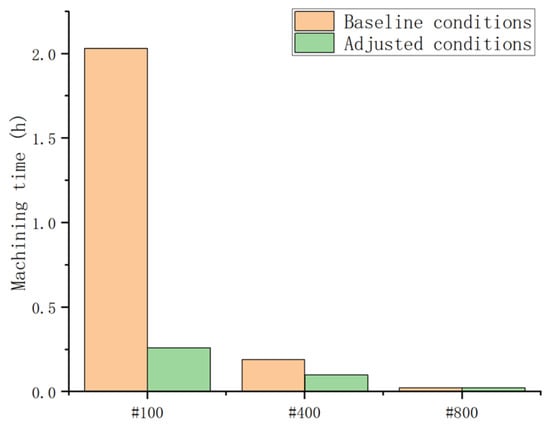
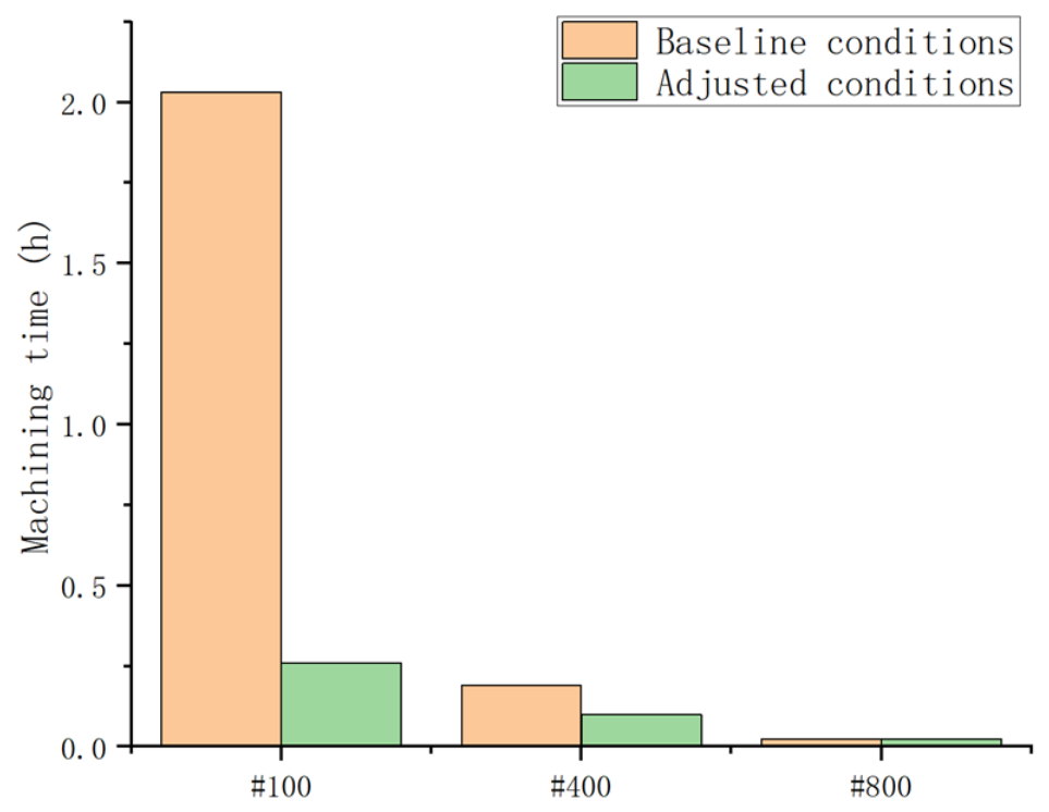
Machining parameters were adjusted for the three machining stages after the baseline comparison. Feed rate, axial depth of cut, and radial depth of cut were assigned according to the grit size used at each stage, as listed in Table 9. Controller-simulated machining time was reduced from 2 h 14 min 56 s under the baseline conditions to 23 min 22 s under the adjusted conditions. A reduction of 82.7% was obtained, as presented in Figure 11. The reduction in simulated machining time was primarily associated with the redistribution of material removal toward the roughing stage. For the #100 diamond point, the feed rate was increased from 200 to 550 mm/min, while the radial depth of cut was increased from 0.015 to 0.025 mm. These changes increased the nominal material-removal capacity and reduced the tool–workpiece contact time required to traverse a given cutting path. Meanwhile, the remaining machining allowance after roughing was reduced from 0.260 to 0.025 mm, so that a greater proportion of the material was removed using the coarser tool at the higher feed rate. For the #400 stage, increasing the radial depth of cut from 0.005 to 0.010 mm and reducing the remaining allowance from 0.050 to 0.012 mm decreased the number of passes required before final finishing. In the controller simulation, machining time was governed primarily by the programmed toolpath length, feed rate, and non-cutting motions. Increasing the feed rate directly reduced the time required to traverse a given cutting path, whereas increasing the radial depth of cut and redistributing the machining allowance reduced the required number of passes and, consequently, the total programmed toolpath length. The axial depth of cut remained at 8 mm during these comparisons and therefore did not contribute to the time reduction. Although the #800 finishing feed rate was reduced from 200 to 100 mm/min to provide more controlled finishing, only a small machining allowance remained after the #400 stage. Consequently, this slower finishing stage did not dominate the total simulated machining time. Therefore, the reported 82.7% reduction represents the combined effects of feed-rate adjustment, radial-depth adjustment, machining-allowance redistribution, and the resulting controller-generated toolpath.
Figure 11.
Controller-simulated machining time under baseline and adjusted machining parameters. The values represent predicted program-execution times rather than experimentally measured machining cycle times.
3.3. Comparison of Full-Profile and Localized Helical Finishing Configurations
Surface roughness values obtained with full-profile helical finishing were Ra 0.454 μm on the flat surface and Ra 0.497 μm in the groove. With localized helical finishing, the corresponding values decreased to Ra 0.352 and 0.429 μm, respectively. These results represent reductions of 22.5% on the flat surface and 13.7% in the groove. The improvement can be related to the different contact distributions produced by the two toolpaths. Full-profile helical finishing was initiated at a Z-coordinate of 0 mm and traversed the entire workpiece profile. Consequently, the #800 diamond point repeatedly contacted regions that had already approached the target dimension. This full-profile re-cutting increased the accumulated tool–workpiece contact length and created a greater possibility of secondary abrasive scratching or excessive removal from previously finished regions. In contrast, localized helical finishing was initiated at a Z-coordinate of −6 mm and restricted the finishing action to the region requiring final correction. At the #800 stage, the axial depth of cut was reduced from 1.00 mm for full-profile finishing to 0.04 mm for localized finishing, while the feed rate and radial depth of cut remained constant at 100 mm/min and 0.006 mm, respectively. The smaller axial increment generated more closely spaced and overlapping abrasive trajectories within the selected region. This localized overlap reduced the spacing between adjacent tool marks and promoted the removal of residual surface asperities, while avoiding unnecessary repeated cutting over the remainder of the workpiece profile. The progressive helical motion may also have facilitated the displacement of detached WC particles toward an open evacuation path, thereby reducing the probability that loose particles were trapped and re-cut between the diamond point and the workpiece. This mechanism is consistent with the lower Ra values obtained using localized finishing. The smaller reduction observed in the groove (13.7%) than on the flat surface (22.5%) may be attributed to the confined groove geometry, which limits cutting-fluid access and debris evacuation and therefore reduces the benefit of toolpath localization. Because debris flow was not measured directly, this explanation should be regarded as a mechanism consistent with the observations rather than direct experimental proof. The staged target dimensions were 17.11, 17.07, and 17.06 mm for the #100, #400, and #800 machining stages, respectively. The dimensional measurements and corresponding errors obtained with full-profile and localized helical finishing are summarized in Table 16 and Table 17, respectively. As shown in these tables, the average dimensional error decreased from 0.139 to 0.137 mm after the #100 stage, from 0.036 to 0.020 mm after the #400 stage, and from 0.004 to 0.001 mm after the #800 stage when localized finishing was used. The largest reduction occurred during the #800 finishing stage, where restricting the finishing region reduced unnecessary removal from surfaces that had already reached the target dimension. The smaller axial increment also allowed the final material removal to be distributed over more closely spaced tool trajectories, resulting in a final dimension closer to the nominal value. However, because the numerical machining parameters used at the #100 and #400 stages were identical for the two strategies, the differences observed at these stages cannot be attributed solely to parameter adjustment and should be interpreted cautiously in the absence of repeated trials.
Table 16.
Dimensional measurements and errors obtained with full-profile helical finishing.
Table 17.
Dimensional measurements and errors obtained with localized helical finishing.
3.4. Application of the Selected Process to Different Tungsten Carbide Grades
Selected machining parameters and the localized helical finishing toolpath were applied to TR15C and KG5, and the resulting machining performance was compared with that obtained for DR14C. The target dimensions for the #100, #400, and #800 machining stages were maintained at 17.11, 17.07, and 17.06 mm, respectively, with 17.06 mm defined as the final finishing dimension. After finishing, the measured surface roughness values (Ra) for TR15C were 0.428 μm on the flat surface and 0.281 μm in the groove, whereas the corresponding values for KG5 were 0.428 and 0.436 μm, respectively. Thus, TR15C and KG5 exhibited the same roughness on the flat surface, while the groove roughness of TR15C was 0.155 μm lower than that of KG5. The surface roughness results for KG5 were also comparable to the corresponding results obtained for DR14C. The dimensional results for TR15C and KG5 are presented in Table 18 and Table 19, respectively. The dimensional errors measured for KG5 were close to those obtained for DR14C, whereas smaller dimensional errors were observed for TR15C during the #100 roughing stage. These results support the practical feasibility of the integrated workflow under the tested conditions. However, the individual contributions and interactions of ultrasonic assistance, parameter adjustment, and finishing configuration were not independently quantified, and independently repeated trials are required to establish statistical repeatability and generality.
Table 18.
Dimensional measurements and errors for TR15C.
Table 19.
Dimensional measurements and errors for KG5.
3.5. SEM and BSE Characterization of Machined Tungsten Carbide Surfaces
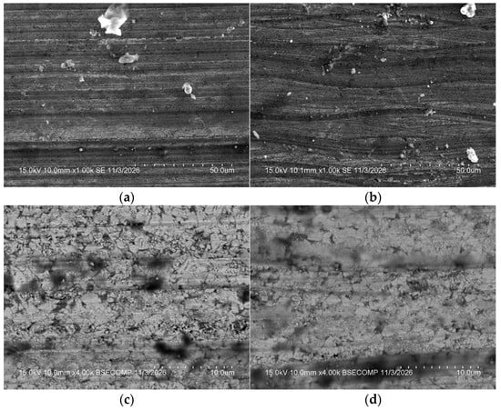
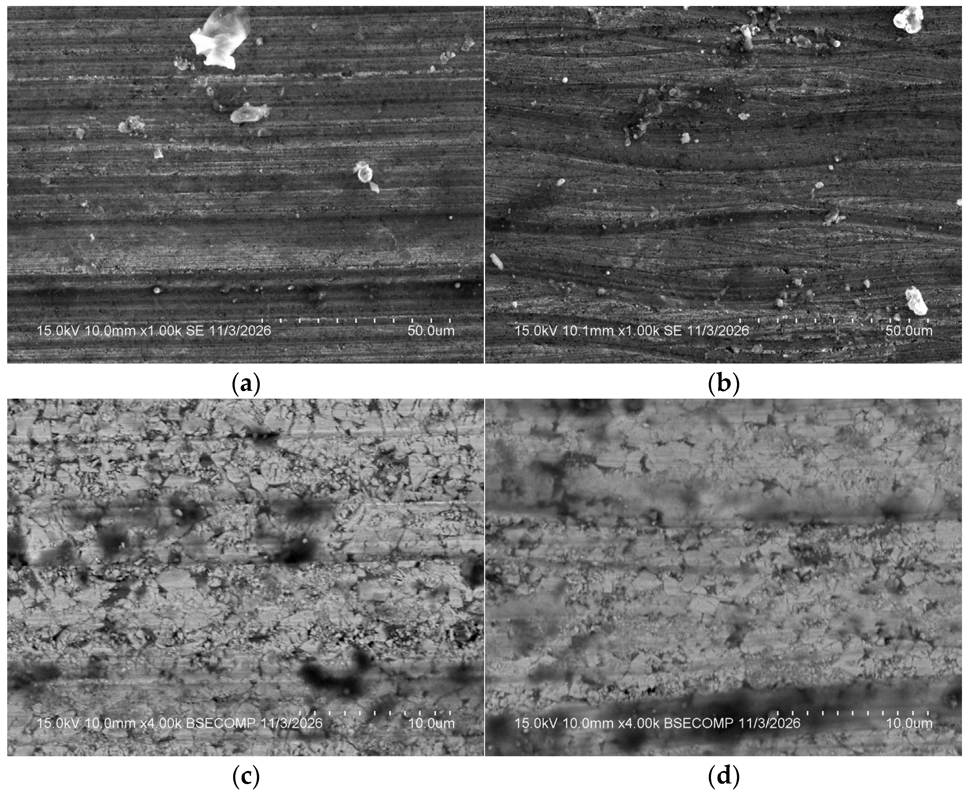
Scanning electron microscopy (SEM) and backscattered electron (BSE) imaging were performed to investigate the surface morphology and microstructural contrast of the machined tungsten carbide specimens. Surface characterization was conducted at magnifications of 1000× and 4000×. Three experimental comparisons were established to evaluate the surface characteristics associated with machining conditions, finishing strategies, and material properties. Conventional machining and ultrasonic-assisted machining (USM) were first compared using DR14C specimens. Full-profile and localized helical finishing were subsequently evaluated on the flat and groove surfaces of DR14C. Finally, the surface characteristics of DR14C, TR15C, and KG5 after localized helical finishing were examined. The microscopic observations were evaluated together with the corresponding surface roughness measurements. The surface morphologies of DR14C after conventional machining and USM are presented in Figure 12. The SEM images in Figure 12a,b exhibit predominantly parallel machining marks along the cutting direction, accompanied by localized surface irregularities and scattered particulate features. Differences in the appearance and continuity of the machining marks were observed between the two machining conditions. The corresponding BSE images in Figure 12c,d exhibited heterogeneous grayscale contrast and granular microstructural features within the machined surface regions. These characteristics reflected variations in the local microstructural contrast of the cemented carbide surfaces. Under identical baseline machining conditions, the measured surface roughness decreased from Ra 0.600 to 0.510 μm on the flat surface and from Ra 0.617 to 0.504 μm in the groove, corresponding to reductions of 15.0% and 18.3%, respectively. The combination of directional machining marks, local surface features, and measured roughness provided complementary evidence for evaluating the surface-quality response associated with ultrasonic assistance.
Figure 12.
SEM and BSE images of DR14C surfaces after conventional machining and ultrasonic-assisted machining: (a) conventional machining, SEM at 1000×; (b) ultrasonic-assisted machining, SEM at 1000×; (c) conventional machining, BSE at 4000×; and (d) ultrasonic-assisted machining, BSE at 4000×.
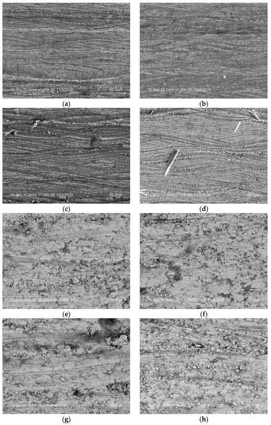
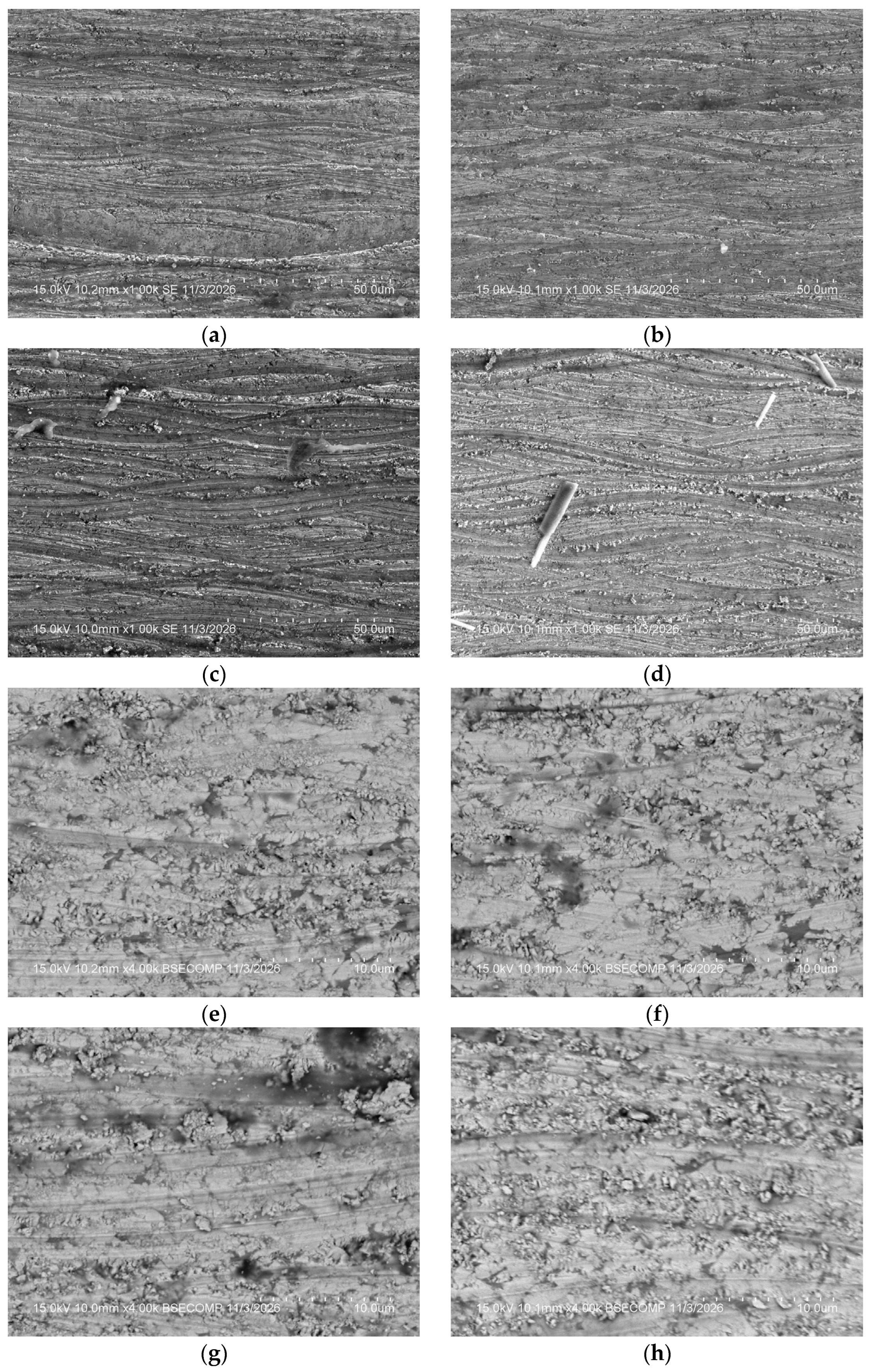
The surface morphologies produced by full-profile and localized helical finishing of DR14C are compared in Figure 13. The SEM images of the flat surfaces in Figure 13a,b exhibited directional machining marks distributed along the finishing paths. In contrast, the groove surfaces in Figure 13c,d exhibited curved machining traces associated with the geometric configuration of the machined regions. Localized particulate features and variations in the continuity of the surface traces were also observed. The corresponding BSE images in Figure 13e–h revealed granular microstructural contrast and local variations in surface appearance across the different finishing regions. The finishing configurations produced different tool–workpiece engagement paths, with full-profile helical finishing covering the complete workpiece profile and localized helical finishing concentrating the final machining operation within the designated finishing region. The surface roughness decreased from Ra 0.454 to 0.352 μm on the flat surface and from Ra 0.497 to 0.429 μm in the groove after localized helical finishing, corresponding to reductions of 22.5% and 13.7%, respectively. These results demonstrated that the selected finishing-toolpath configuration influenced the resulting surface characteristics and achieved lower measured roughness under the investigated conditions.
Figure 13.
SEM and BSE images of DR14C surfaces after full-profile and localized helical finishing: (a–d) SEM images of flat and groove surfaces at 1000×; and (e–h) corresponding BSE images at 4000×. The images were arranged to compare full-profile and localized finishing under the same surface configurations.
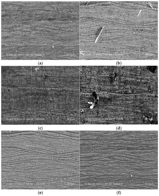
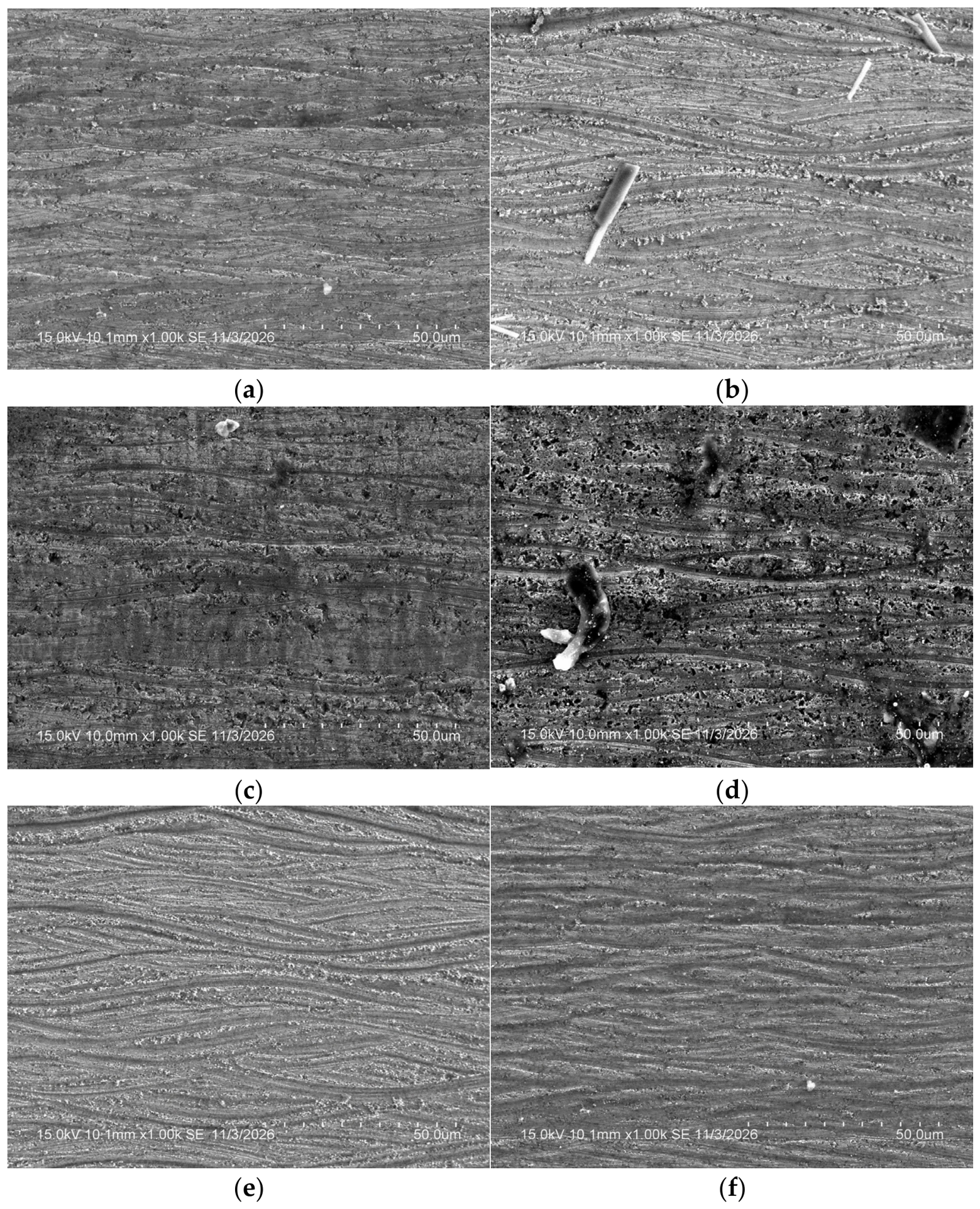
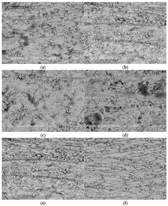
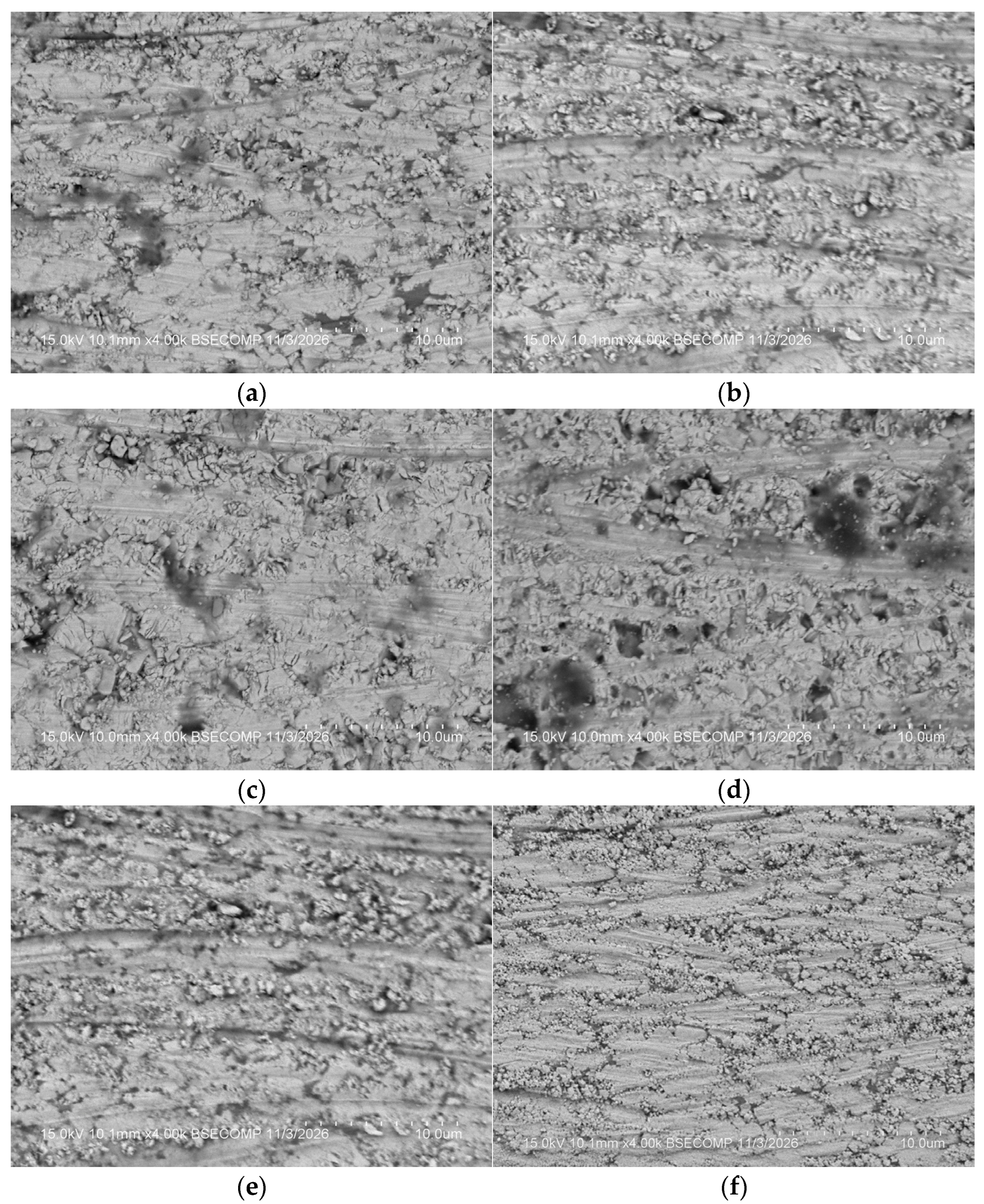
The surface morphologies of DR14C, TR15C, and KG5 after localized helical finishing are presented in Figure 14 and Figure 15. The SEM images in Figure 14 exhibited directional machining traces across the flat and groove surfaces of all three tungsten carbide grades. DR14C exhibited fine machining marks and localized surface irregularities, whereas TR15C exhibited more distinct dark surface features and scattered particulate regions within the observed fields. KG5 exhibited curved and closely spaced machining traces with local variations in surface texture. The BSE images in Figure 15 further revealed granular microstructural contrast and differences in the appearance of the constituent surface regions among the three materials. The measured surface roughness values on the flat and groove surfaces were Ra 0.352 and 0.429 μm for DR14C, Ra 0.428 and 0.281 μm for TR15C, and Ra 0.428 and 0.436 μm for KG5, respectively. DR14C exhibited the lowest flat-surface roughness of Ra 0.352 μm, while TR15C exhibited the lowest groove roughness of Ra 0.281 μm. These findings demonstrated material-dependent differences in the surface response obtained using the selected localized helical finishing strategy. The microscopic observations and surface roughness measurements provided complementary characterization of the finishing results across the three commercial tungsten carbide grades.
Figure 14.
SEM images of three tungsten carbide grades after localized helical finishing at 1000×: (a,b) flat and groove surfaces of DR14C; (c,d) flat and groove surfaces of TR15C; and (e,f) flat and groove surfaces of KG5.
Figure 15.
BSE images of three tungsten carbide grades after localized helical finishing at 4000×: (a,b) flat and groove surfaces of DR14C; (c,d) flat and groove surfaces of TR15C; and (e,f) flat and groove surfaces of KG5.
The SEM and BSE observations provided additional evidence of the surface characteristics associated with ultrasonic assistance, finishing-toolpath configuration, and tungsten carbide grade. The corresponding elemental compositions were further investigated using energy-dispersive X-ray spectroscopy (EDS), as presented in Section 3.6.
3.6. Elemental Composition Analysis of Tungsten Carbide Specimens
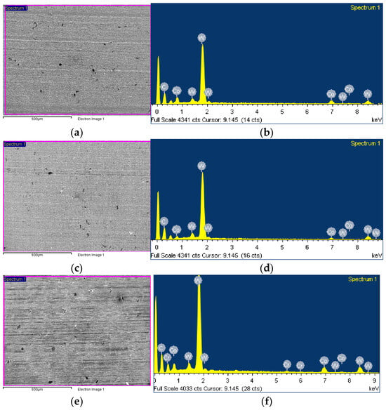
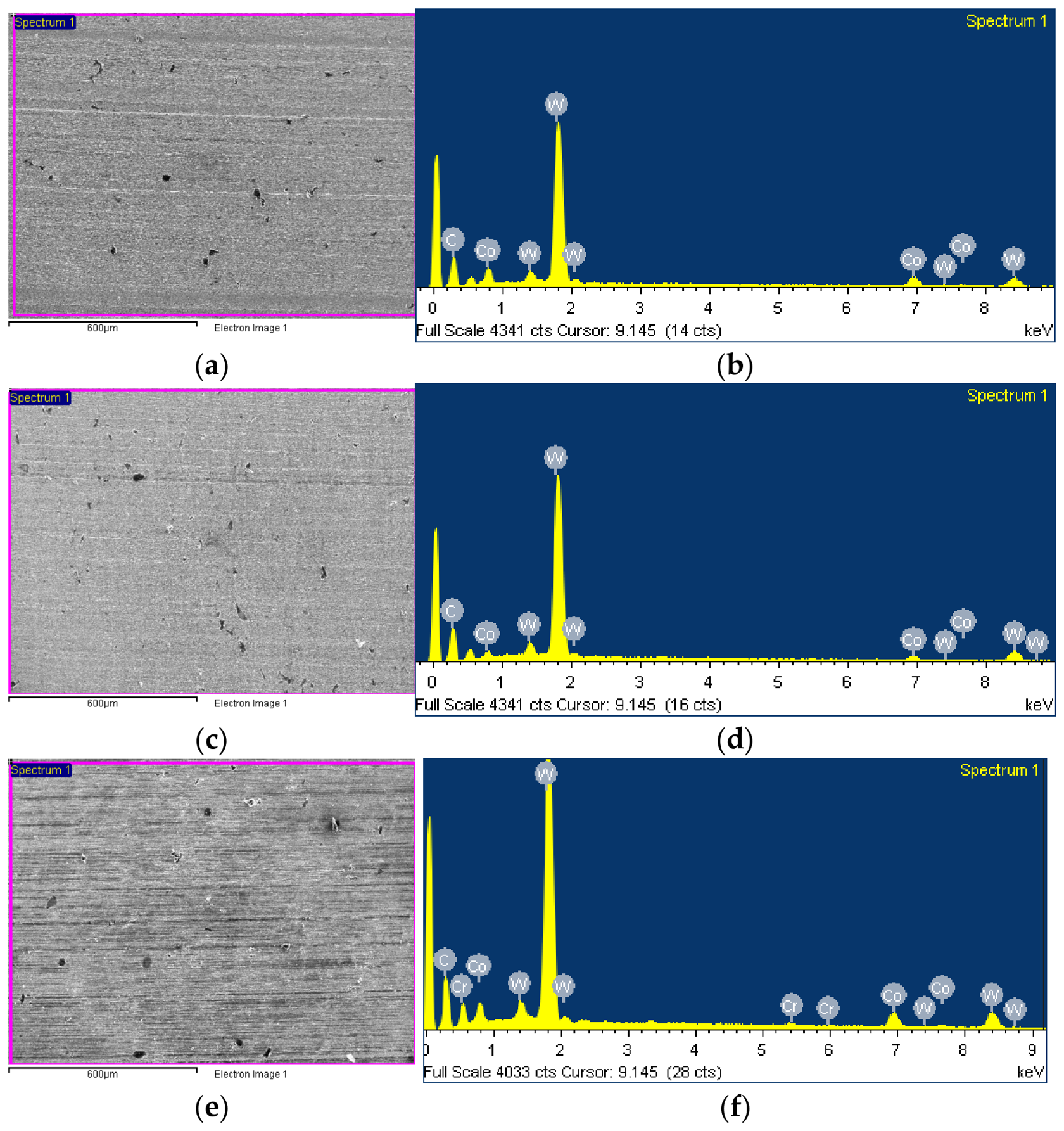
Energy-dispersive X-ray spectroscopy (EDS) was performed to characterize the elemental compositions of the DR14C, TR15C, and KG5 tungsten carbide specimens. The corresponding electron images and EDS spectra are presented in Figure 16, while the quantitative elemental compositions are summarized in Table 20. Carbon (C), cobalt (Co), and tungsten (W) were detected in all three specimens. DR14C exhibited elemental concentrations of 21.61 wt.% C, 12.06 wt.% Co, and 66.33 wt.% W. TR15C exhibited concentrations of 23.29 wt.% C, 4.47 wt.% Co, and 72.24 wt.% W. KG5 exhibited concentrations of 21.93 wt.% C, 9.84 wt.% Co, 67.71 wt.% W, and 0.52 wt.% Cr. Chromium (Cr) was additionally identified in KG5, indicating the presence of a minor constituent within the analyzed surface region. The EDS results revealed differences in the elemental distributions among the three tungsten carbide grades. Tungsten exhibited the highest measured weight percentage in all specimens, followed by carbon and cobalt. TR15C exhibited the highest W concentration at 72.24 wt.% and the lowest Co concentration at 4.47 wt.%. DR14C exhibited the highest Co concentration at 12.06 wt.%, whereas KG5 exhibited an intermediate Co concentration of 9.84 wt.%. The measured elemental concentrations reflected the characteristics of the analyzed surface regions and provided supplementary compositional information for the three tungsten carbide grades. The EDS results complemented the nominal material compositions presented in Table 8 and supported the comparative characterization of the tungsten carbide specimens.
Figure 16.
Electron images and EDS spectra of the machined tungsten carbide specimens: (a,b) DR14C; (c,d) TR15C; and (e,f) KG5.
Table 20.
EDS elemental compositions of the machined tungsten carbide specimens.
4. Conclusions
An integrated CNC machining workflow combining ultrasonic-assisted machining (USM), stage-specific parameter allocation, and localized helical finishing was developed and evaluated for precision machining of tungsten carbide (WC). Under identical baseline machining conditions, USM reduced the surface roughness of DR14C from Ra 0.600 to 0.510 μm on the flat surface and from Ra 0.617 to 0.504 μm in the groove, corresponding to reductions of 15.0% and 18.3%, respectively. Confocal measurements further revealed reductions in mean Ra from 0.255 to 0.133 μm and mean Rz from 2.208 to 1.560 μm. Stage-specific adjustment of machining parameters and toolpath configuration reduced the CNC controller-simulated machining time from 2 h 14 min 56 s to 23 min 22 s, representing an 82.7% reduction in predicted processing time. Localized helical finishing further decreased Ra from 0.454 to 0.352 μm on the flat surface and from 0.497 to 0.429 μm in the groove, corresponding to reductions of 22.5% and 13.7%, respectively. The selected machining workflow was applied to DR14C, TR15C, and KG5, achieving final flat-surface roughness values of Ra 0.352, 0.428, and 0.428 μm, respectively. SEM and BSE observations provided supplementary characterization of the machined surface morphology and microstructural contrast, while EDS analysis identified the principal constituent elements of the three WC grades. These findings demonstrated the effectiveness of integrating ultrasonic assistance, machining-parameter adjustment, and localized helical finishing for improving surface quality and controller-predicted processing efficiency under the investigated conditions.
Author Contributions
Conceptualization, C.-K.Y.; methodology, C.-K.Y.; software, W.-L.H. and X.-Y.L.; validation, S.-K.C.; formal analysis, W.-L.H., X.-Y.L. and S.-K.C.; investigation, W.-L.H., X.-Y.L. and S.-K.C.; resources, C.-K.Y.; data curation, S.-K.C.; writing—original draft preparation, W.-L.H. and X.-Y.L.; writing—review and editing, C.-K.Y.; visualization, C.-K.Y.; supervision, C.-K.Y.; project administration, C.-K.Y.; funding acquisition, C.-K.Y. All authors have read and agreed to the published version of the manuscript.
Funding
This research was funded by the National Science and Technology Council (NSTC), Taiwan, under grant numbers NSTC 114-2622-E-214-001, NSTC 115-2221-E-214-010, and NSTC 114-2221-E-214-013, for which the authors express their sincere gratitude.
Data Availability Statement
The raw data supporting the conclusions of this article will be made available by the authors on request.
Acknowledgments
The authors gratefully acknowledge the financial support provided by the National Science and Technology Council (NSTC), Taiwan. The support enabled the completion of the experimental work, system development, and data analysis presented in this study and contributed to the successful completion of this research.
Conflicts of Interest
The authors declare no conflicts of interest.
References
- Ortner, H.M.; Ettmayer, P.; Kolaska, H. The history of the technological progress of hardmetals. Int. J. Refract. Met. Hard Mater. 2014, 44, 148–159. [Google Scholar] [CrossRef] [Scilit]
- Exner, H.E. Physical and chemical nature of cemented carbides. Int. Met. Rev. 1979, 24, 149–173. [Google Scholar] [CrossRef] [Scilit]
- Armstrong, R.W. The hardness and strength properties of WC–Co composites. Materials 2011, 4, 1287–1308. [Google Scholar] [CrossRef] [Scilit] [PubMed]
- Roebuck, B.; Almond, E.A. Deformation and fracture processes and the physical metallurgy of WC–Co hardmetals. Int. Mater. Rev. 1988, 33, 90–110. [Google Scholar] [CrossRef]
- Chaporova, I.N.; Shchetlina, Y.A. Investigations of the carburizing process in tungsten carbide hard alloys with cobalt and nickel. In Hard Metals Production Technology and Research in the U.S.S.R.; Bashkirov, S.I., Ed.; Pergamon Press: Oxford, UK, 1964; pp. 196–211. Available online: https://shop.elsevier.com/books/hard-metals-production-technology-and-research-in-the-ussr/bashkirov/978-0-08-010267-2 (accessed on 30 June 2026).
- Chaporova, I.N.; Tret’yakov, V.I.; Shchetina, E.A.; Makarenko, T.G. The solid solubilities of some stable carbides in cobalt, nickel and iron at 1250 °C. In Hard Metals Production Technology and Research in the U.S.S.R.; Bashkirov, S.I., Ed.; Pergamon Press: Oxford, UK, 1964; pp. 165–178. Available online: https://shop.elsevier.com/books/hard-metals-production-technology-and-research-in-the-ussr/bashkirov/978-0-08-010267-2 (accessed on 30 June 2026).
- Genga, R.M.; Cornish, L.A.; Akdogan, G. Effect of Mo2C additions on the properties of SPS-manufactured WC–TiC–Ni cemented carbides. Int. J. Refract. Met. Hard Mater. 2013, 41, 12–21. [Google Scholar] [CrossRef] [Scilit]
- Liu, C.; Lin, N.; He, Y.; Wu, C.; Jiang, Y. The effects of micron WC contents on the microstructure and mechanical properties of ultrafine WC–(micron WC–Co) cemented carbides. J. Alloys Compd. 2014, 594, 76–81. [Google Scholar] [CrossRef] [Scilit]
- Pötschke, J.; Richter, V.; Gestrich, T.; Michaelis, A. Grain growth during sintering of tungsten carbide ceramics. Int. J. Refract. Met. Hard Mater. 2014, 43, 309–316. [Google Scholar] [CrossRef] [Scilit]
- Pötschke, J.; Richter, V.; Holke, R. Influence and effectivity of VC and Cr3C2 grain growth inhibitors on sintering of binderless tungsten carbide. Int. J. Refract. Met. Hard Mater. 2012, 31, 218–223. [Google Scholar] [CrossRef] [Scilit]
- Zeng, K.; Wu, X.; Jiang, F.; Shen, J.; Zhu, L.; Li, L. A comprehensive review on the cutting and abrasive machining of cemented carbide materials. J. Manuf. Process. 2023, 108, 335–358. [Google Scholar] [CrossRef] [Scilit]
- Chiu, T.-Y. The Study of Ultrasonic Vibration Assisted High-Speed Milling Inconel 718. Master’s Thesis, National Taiwan University, Taipei, Taiwan, 2022. [Google Scholar] [CrossRef]
- Liao, L.-Y.; Liao, Y.-H. A study of single point diamond turning of tungsten carbide. J. Ind. Mechatron. 2017, 414, 57–64. [Google Scholar]
- Shimada, S.; Tanaka, H.; Higuchi, M.; Yamaguchi, T.; Honda, S.; Obata, K. Thermo-chemical wear mechanism of diamond tool in machining of ferrous metals. CIRP Ann. 2004, 53, 57–60. [Google Scholar] [CrossRef] [Scilit]
- Lai, T.-Y. Study of Ultra-Precision Diamond Turning of Ferrous Alloys. Master’s Thesis, National Taiwan University, Taipei, Taiwan, 2016. [Google Scholar] [CrossRef]
- Lin, Y.-C.; Hwang, L.-R. Machining characteristics of sintered tungsten carbide via EDM. Chung Chou J. 2002, 15, 292–305. [Google Scholar]
- Hantop Intelligence Tech. Official Website. Available online: https://www.hit-tw.com/tw/ (accessed on 30 June 2026).
- Pan, G.-W. Study on High Speed Micro Milling with Vibration Machining. Master’s Thesis, National Yunlin University of Science and Technology, Yunlin, Taiwan, 2004. Available online: https://ndltd.ncl.edu.tw/cgi-bin/gs32/gsweb.cgi/login?o=dnclcdr&s=id%3D%22092YUNT5489027%22.&searchmode=basic (accessed on 30 June 2026).
- Ji, N.; Zhang, J.; Liu, M.; Dai, H.; Ding, K.; Yu, J.; Zhang, X. Experimental Investigation of Ultrasonic Vibration-Assisted Grinding of HVOF-Sprayed WC-10Co-4Cr Coating. Coatings 2023, 13, 1788. [Google Scholar] [CrossRef] [Scilit]
- Martins, H.; Puga, H. Ultrasonic Assisted Machining Overview: Accessing Feasibility and Overcoming Challenges for Milling Applications. Metals 2023, 13, 908. [Google Scholar] [CrossRef] [Scilit]
- Beju, L.D.; Brindasu, D.P.; Vulc, S. Grinding tungsten carbide used for manufacturing gun drills. Stroj. Vestn. J. Mech. Eng. 2015, 61, 571–582. [Google Scholar] [CrossRef] [Scilit]
- Kataria, R.; Singh, R.P.; Kumar, J. An experimental study on ultrasonic machining of tungsten carbide-cobalt composite materials. AIMS Mater. Sci. 2016, 3, 1391–1409. [Google Scholar] [CrossRef] [Scilit]
- Kataria, R.; Kumar, J.; Pabla, B.S. Experimental investigation of surface quality in ultrasonic machining of WC-Co composites through Taguchi method. AIMS Mater. Sci. 2016, 3, 1222–1235. [Google Scholar] [CrossRef] [Scilit]
- Feng, G.; Wang, T.; Huang, Q.; Guo, W.; Liu, R. Experimental study on ultra-precision grinding characteristics of WC–Ni hard metals. Proc. Inst. Mech. Eng. Part B J. Eng. Manuf. 2020, 234, 600–609. [Google Scholar] [CrossRef] [Scilit]
- Hsue, A.W.-J.; Zheng, Y.-Z. A novel flexible tool with rotary ultrasonic spindle for fine grinding of tungsten carbide. MATEC Web Conf. 2018, 185, 00018. [Google Scholar] [CrossRef] [Scilit]
- Guo, B.; Zhao, Q. Ultrasonic vibration assisted grinding of hard and brittle linear micro-structured surfaces. Precis. Eng. 2017, 48, 98–106. [Google Scholar] [CrossRef] [Scilit]
- Yavuzbarut, T.; Sandal, E.; Aydın, K.B. Investigation of the ultrasonic effect on surface topography of WC-Co in grinding operation with different cutting variants. J. Adv. Manuf. Eng. 2025, 6, 14–21. [Google Scholar] [CrossRef] [Scilit]
- Riu-Perdrix, G.; Slawik, S.; Mücklich, F.; Llanes, L.; Roa, J.J. Influence of Different Shaping and Finishing Processes on the Surface Integrity of WC-Co Cemented Carbides. Metals 2024, 14, 52. [Google Scholar] [CrossRef] [Scilit]
- Ren, Y.H.; Zhang, B.; Zhou, Z.X. Specific energy in grinding of tungsten carbides of various grain sizes. CIRP Ann.–Manuf. Technol. 2009, 58, 299–302. [Google Scholar] [CrossRef] [Scilit]
- Molaie, M.M.; Zahedi, A.; Akbari, J. Effect of water-based nanolubricants in ultrasonic vibration assisted grinding. J. Manuf. Mater. Process. 2018, 2, 80. [Google Scholar] [CrossRef] [Scilit]
- Wen, D.; Shi, Y.; Cao, Y.; Zhao, J.; Ding, W.; Zhao, B. Material removal mechanisms during ultrasonic vibration-assisted grinding of WC-10Co-4Cr coatings with a single diamond grain. Int. J. Adv. Manuf. Technol. 2025, 139, 4747–4757. [Google Scholar] [CrossRef] [Scilit]
- Wen, D.; Wang, Z.; Shi, Y.; Zhou, P.; Xiang, H.; Yu, W.; Liu, Q.; Zhao, B.; Ding, W. Surface integrity evolution of WC-10Co-4Cr coating under tangential ultrasonic vibration-assisted grinding. Int. J. Adv. Manuf. Technol. 2026, 142, 3421–3432. [Google Scholar] [CrossRef] [Scilit]
- Wu, C.; Song, Z.; Li, S.; Wang, Q.; Jiang, N.; Liang, S.Y. Laser pre-softening assisted grinding process and material removal mechanisms of WC-Co cemented carbide. Ceram. Int. 2026, 52, 35779–35794. [Google Scholar] [CrossRef] [Scilit]
- Peng, R.; Zhang, W.; Zhao, L.; Gao, J. Process-parameter effects in WC–Co cemented carbide creep-feed grinding. Mater. Manuf. Process. 2026, 41, 779–790. [Google Scholar] [CrossRef] [Scilit]
- Peng, R.; Yang, Z.; Yang, Q.; Zhang, Y.; Huang, X.; Zhao, L. Multi-scale investigation of surface integrity and removal mechanisms in precision grinding of WC-Co carbide. Precis. Eng. 2026, 101, 96–113. [Google Scholar] [CrossRef] [Scilit]
- Gu, P.; Zhou, Y.; Tan, L.; Ren, M.; Zhang, X.; Xiong, Y.; Liu, X.; Zhu, L. Ultra-precision grinding process for optical surfaces with microstructure arrays: Surface generation and error compensation. Precis. Eng. 2026, 101, 199–215. [Google Scholar] [CrossRef] [Scilit]

Disclaimer/Publisher’s Note: The statements, opinions and data contained in all publications are solely those of the individual author(s) and contributor(s) and not of MDPI and/or the editor(s). MDPI and/or the editor(s) disclaim responsibility for any injury to people or property resulting from any ideas, methods, instructions or products referred to in the content. |
© 2026 by the authors. Published by MDPI on behalf of the International Institute of Knowledge Innovation and Invention. Licensee MDPI, Basel, Switzerland. This article is an open access article distributed under the terms and conditions of the Creative Commons Attribution (CC BY) license.