


Abstract
Metal–polymer hybrid composites blend the high strength and stiffness of metals with the low weight and corrosion resistance of polymers. This synergy is expected to provide better crashworthiness, energy absorption, and design flexibility compared to traditional single-material structures. The present research intended to examine the crashworthiness features of an aluminium/CFRP structure under various operating conditions by optimizing process parameters through Design Expert software and experimental investigation. The design of the experiment was carried out using Design Expert software version 13 with response surface methodology (RSM) where working temperature, isothermal holding time, and crushing speed are taken as process variables. The test results demonstrate that the peak load, energy absorption (EA), and specific energy absorption (SEA) are significantly higher for the sample with working temperature, isothermal holding time, and crushing speed set at 25 °C, 13 h, and 5 mm/min, respectively. Moreover, EA and SEA are also relatively higher for this sample compared to the other samples. The test results showcased that temperature is a decisive factor for the mechanical properties of the tube, which is clearly reflected in experimental results. The higher peak force and EA indicate greater strength and a more energy-dissipative system. Moreover, a close correlation was observed between the experimentally measured and RSM-based optimization. Hence, RSM was found to be suitable for designing the experiments and for understanding the failure modes of the CFRP/aluminium structure.
1. Introduction
Over the years, traditional metals have been recognized as a leading material for various engineering applications owing to their superior mechanical properties [1]. Lately, composite materials such as carbon fiber reinforced polymers (CFRP) have been increasingly popular in replacing conventional materials for developing lightweight and high-strength materials to target specific properties like stiffness, strength, and impact performance [2]. Extensive research has been performed on thin-walled metal and composite structures, with emphasis on crushing performance, failure modes, and energy absorption (EA) under axial load [3,4,5]. Initially, pure composites were investigated for crashworthiness behavior; however, researchers later shifted their focus to hybrid composite alloys [6]. Owing to their slower crack propagation, progressive crushing, and higher specific energy absorption (SEA) under compressive loads, hybrid composite alloys were preferred over traditional composites. For instance, Shin et al. [7] explored an aluminium/glass fiber-reinforced polymer hybrid square tube to investigate EA response under axial and bending load [8]. The study confirmed that the hybrid tube with 90° ply sequencing showcased the best EA compared to 0° and ±45° sequencing. The average crushing load is affected by the thickness of the tube. However, for the bending collapsing assessment, 0°/90° ply orientation outperformed the rest hybrid tube orientations [9]. Later on, the crashworthiness of the aluminium/CFRP hybrid square section was investigated [10,11]. They have observed that composite collapses by axisymmetric, non-axisymmetric, and compound modes [12,13]. The study confirmed that the collapse mode is directional-sensitive, the failure mode is axisymmetric when stacking is 15°, whereas for 45° stacking, it is almost non-axisymmetric [14]. In continuation, the crushing behavior of glass/polyester composite tubes with varied geometries (circular, conical, hourglass, square, and hexagonal), thickness, and triggering mechanisms was investigated by Palanivelu et al. [15]. They revealed that geometries and dimensional ratios significantly improve the failure modes and EA [16,17]. The maximum SEA was recorded for hourglass and conical geometries.
Furthermore, the crushing behavior of a CFRP square tube with aluminium honeycomb filling was studied by Liu et al. [18]. The outcome of the study confirmed that the peak load and EA increased by more than 10% with filled aluminium honeycomb compared to bare CFRP, from 12.41% to 27.22% and from 10.49% to 21.83%, respectively [19]. They reported that the increment in crushing behavior of aluminium honeycomb-filled CFRP is due to asymmetrical deformation during the application of load. In another work, Liu et al. [20] evaluated the lateral and bending response of the same sample and reported that aluminium honeycomb-filled CFRP designs are more capable of EA and SEA. Furthermore, Tamer A. Sebaey [21] investigated the influence of pre-crushing temperatures (90 °C to 180 °C) on the crashworthiness behavior of carbon/epoxy composite rectangular tubes when subjected to axial compression [22,23]. The study highlighted a 40% drop in load-carrying capacity and a 70% decrease in EA as the temperature increased from room temperature (RT) to 120 °C. This degradation was attributed to the reduced interfacial strength caused by thermal aging. To assess superior crashworthiness under transverse load, aluminium–basalt/glass hybrid composite tubes with multi-walled carbon nanotube fillers were investigated [24,25]. The experimental outcome demonstrated that incorporating carbon nanotubes helps in reducing delamination and fiber fracture due to strong interfacial bonding [26].
Recent literature emphasizes the increasing importance of metal–polymer hybrid and composite systems across transportation, infrastructure, healthcare, and energy sectors [27]. A comprehensive review details multi-material hybrid structures and advanced joining methods, such as rapid mechanical and thermomechanical interlocking, for weight reduction and enhanced strength [28]. An experimental study demonstrates GFRP-wrapped aluminium cylinders under axial compression, with response surface methodology (RSM) analysis confirming improved crashworthiness. Recently, a review article by Akhtar et al. [29] highlighted the potential of metal-oxide–polymer hybrid composites in various fields, including biomedical, energy storage, chemical, thermal stability, electrical conductivity, and more. The study confirms the growing significance and research opportunities of metal-oxide–polymer hybrid composites [30].
Based on the studies mentioned above, it is confirmed that the crashworthiness characteristics of different composite tubes are generally influenced by various parameters such as material type and properties, orientation/lay-up sequence, volume fraction, tube geometry, cross-sectional shape, manufacturing method, loading conditions, crushing rate, temperature, humidity and boundary conditions [29,31]. Despite the articles mentioned above, systematic experimental and numerical studies of CFRP with metal structures are still lacking. The detailed analysis of how various process parameters and their interactions affect the crashworthiness of CFRP–metal structures remains unclear, requiring comprehensive experimental research. In this study, only three different parameters, namely, working temperature, isothermal holding time, and crushing speed, were considered for an axial crushing test of aluminium/CFRP composite [32,33]. In the present study, to the best of our knowledge, the design of the experiment was conducted for the first time using Design Expert software via RSM to optimize a large number of process variables. Over time, optimization techniques, especially RSM, have been adopted in research as they provide a systematic and statistical framework to analyze process variables with fewer experimental runs. Moreover, RSM helps in implementing efficient and cost-effective methods to better capture variable interactions. The optimal parameters and the interactions among selected parameters were studied to maximize crashworthiness characteristics.
2. Materials and Methods
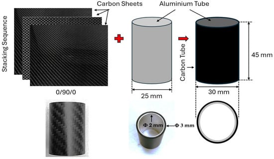
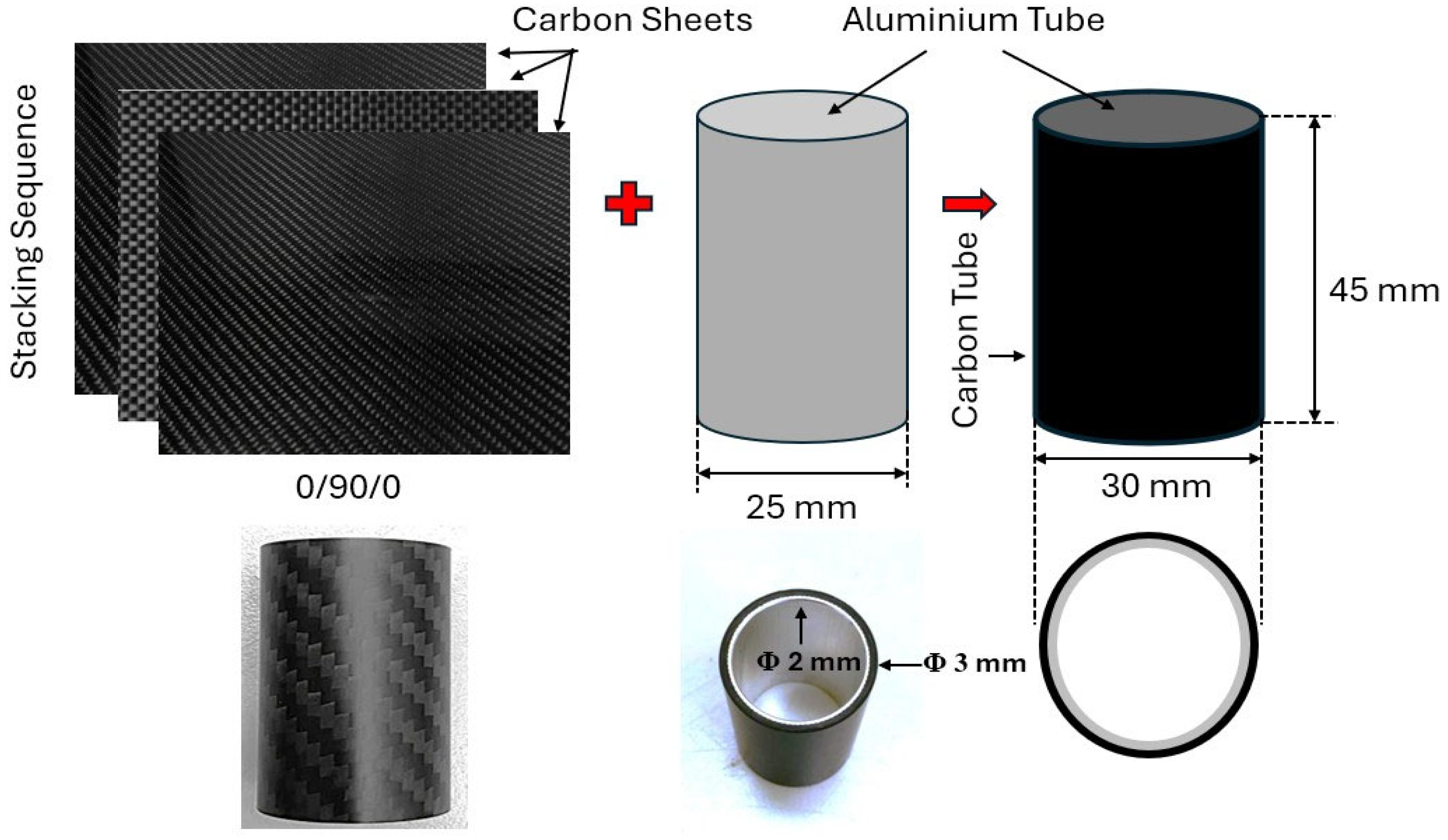
The crashworthiness of thin-walled circular aluminium/CFRP tubes exposed to axial compression was examined, as presented in Figure 1. The specimens were prepared using aluminium alloy 6063-T6, with the corresponding properties provided in Table 1. Aluminium alloy 6063 is selected for this study as it offers a balance of adhesion and compatibility with CFRP wrapping to reproduce crushing behavior.
Figure 1.
Shape and size of thin-walled aluminium/CFRP tube.
Table 1.
Properties of aluminium specimens [34].
CFRP specimens were produced in-house using a 0°/90° woven T300 carbon fiber/epoxy prepreg system. The specific material properties of the yarn and the resin are given in Table 2.
Table 2.
Properties of yarn [34].
The composite tube samples were supplied by Toray, known for their exceptional reliability and excellent processability in standard procedures like weaving, braiding, filament winding, and prepreg. In this experimental study, a composite hybrid tube was constructed with a round aluminium tube (inner and outer diameter of 25 mm and 30 mm, respectively, 45 mm long) wrapped with carbon fiber. The carbon fiber layer was very thin at just 1.5 mm and arranged in a nearly balanced sequence of ±45°/0°/90°/0°/0°/±45° to enhance axial and bending stiffness. The surface treatment of the aluminium tube was carried out using a knurling process, while the carbon fibers were prepared from prepregs through a lay-up method.
The curing behavior of the carbon fiber composite primarily depends on temperature. During processing, the preheating temperature was maintained between 30 and 70 °C, followed by vulcanization at 80 to 90 °C. The final curing was performed at 130 °C for a duration of 150 min. The prepreg used in this study consisted of 67% fiber volume and 33% epoxy resin by weight. During the preparation of around cylindrical tubes, location of the seam where two ends of prepreg meet can influence the stress distribution, failure behavior, and uniformity of the tube. The overlapping of seams leads to localized thickness build up results in asymmetric failure during crushing. This can be avoided by controlled fiber orientation and employing a mandrel so that prepreg edges meet in a butt joint configuration without overlap. The seam effect was controlled by using helical wrapping, debulking during the hand layup process, and ensuring uniform wall thickness to pertain unpredictable crushing behavior. After impregnating the structure with the selected resin and curing it under controlled temperature and pressure, the hybrid tubes were cut and machined into the specified test shapes and sizes. This internal manufacturing process allowed for strict control of material quality and processing conditions. In this study, 13 samples designed using Design Expert software, along with pure aluminium/CFRP samples, were tested for crashworthiness metrics.
2.1. Design of Experiments
This experiment applies RSM with a Box–Behnken Design to optimize three independent variables, namely, working temperature, isothermal holding time, and crushing speed. The ranges of various variables used for conducting experiments are displayed in Table 3. The selection of these variables was guided by insights obtained from a thorough literature review. The selected crushing speed in a range of 2 to 5 mm/min ensures stable progressive crushing, with minimal experimental scatter, and allows consistent contrast between specimens while avoiding dynamic amplification effects.
Table 3.
Range of independent parameters.
The configuration list of the experiments designed using the software is provided in Table 4. The sample IDs range from S1 to S13, where S denotes a particular set. Although a total of 17 experiments were designed using Design Expert software, some repeated experiments were neglected to avoid confusion. All the obtained samples were tested to verify the repeatability of the results. Although experimental results should be based on at least 3 or 5 specimens, the present study is not totally on experiments. The present study aimed to optimize process parameters using Design Expert software where software suggested the best combination of process variables and only one set of data was utilized for experimental work.
Table 4.
Design of experiments using Design Expert software.
Analytical Analysis
Design Expert version 10.0.7.0 was employed for experimental analysis and graphical representation. The response surface regression in this study was modeled using a polynomial Equation (1), expressed as follows:
Here, Y denotes the response, Xi and Xj represent uncoded independent variables, and k is the number of factors optimized. is a coefficient and is a random error [35].
2.2. Axial Crushing Tests
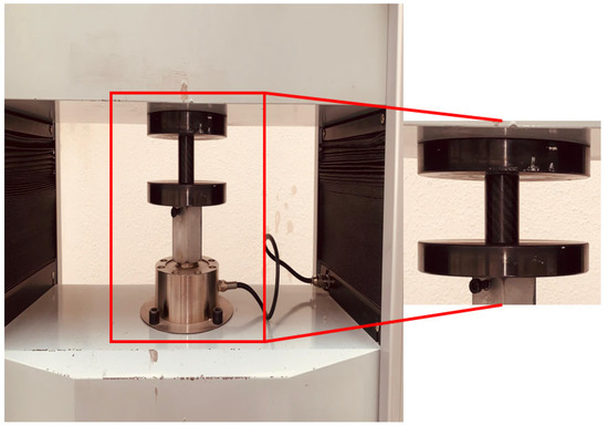
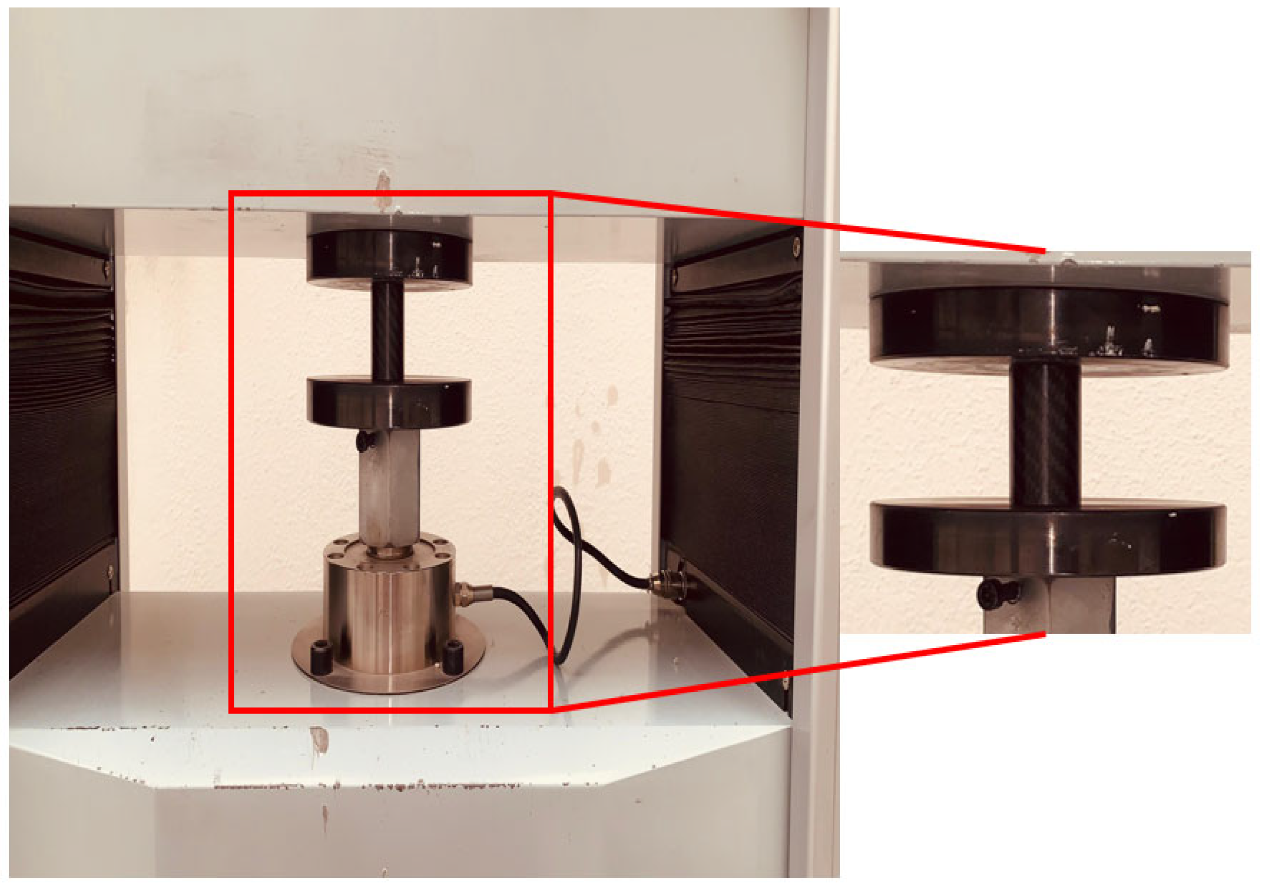
Axial crushing tests were performed at various temperatures, using the 300 kN universal testing machine (UTM) [36,37]. Each tube was installed in the testing machine using the design of experiments as illustrated in Figure 2. The crushing speed at which the jaw moves is set in a range of 2 to 5 mm/min.
Figure 2.
Axial crushing test of hybrid alloy on UTM-300 kN.
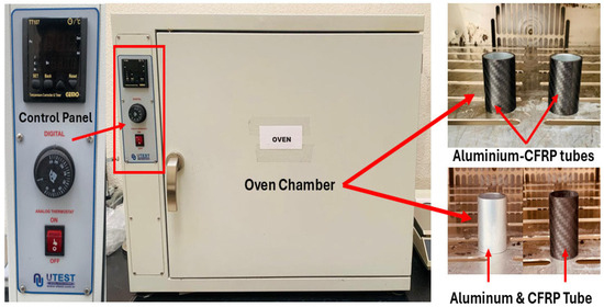
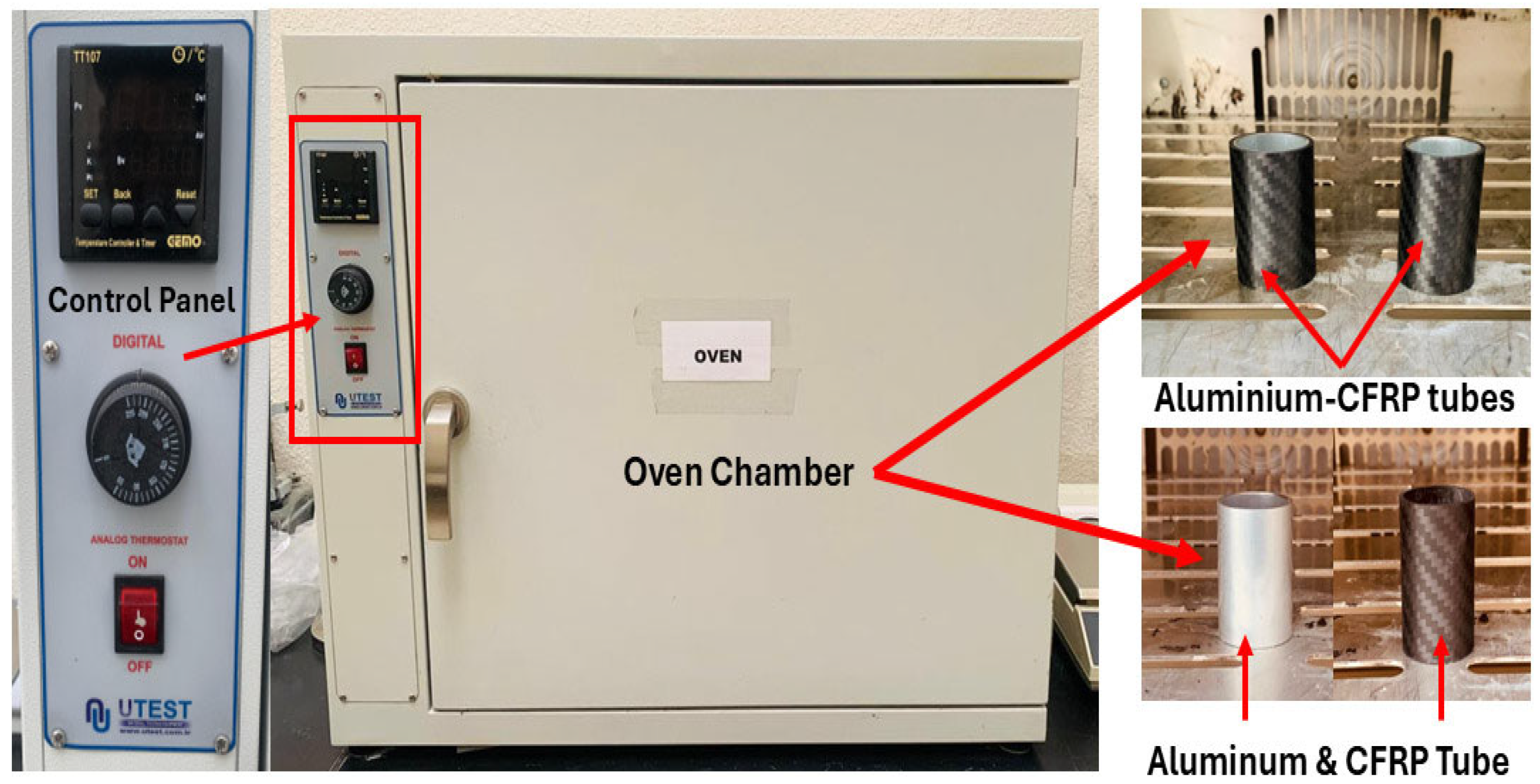
Each specimen was loaded until reaching 80% axial strain or a sudden load drop indicating a loss of load-bearing capacity, at which point the test was stopped. During testing, the machine recorded the entire load–displacement history, which was later converted into stress–strain data and used to calculate crashworthiness parameters such as peak load, mean load, crushing force efficiency, EA, and SEA. Before testing, the specimens were conditioned in an oven at the specified temperature and duration to ensure consistent moisture and thermal states across all samples, as shown in Figure 3.
Figure 3.
Specimens are conditioned in an oven at the specified temperature.
2.3. Crashworthiness Metrics
To assess the crashworthiness of thin-walled aluminium/CFRP structures, several criteria were often used. Each criterion employed to evaluate the crashworthiness properties of the structure is elaborated below.
2.3.1. Peak Load
Peak load (Pmax) relates to the maximum load reached during the pre-crushing stage. It reflects the most significant resistance the structure provides before the material begins to deform progressively.
2.3.2. Mean Crushing Force
Mean crushing load (Pmean) is the average load sustained during the crushing process. It is denoted as the ratio of EA to crushing displacement.
2.3.3. Crush Force Efficiency
Crush force efficiency (CFE) is the ratio of average crushing force to primary Pmax. A higher CFE indicates better crash performance, as described by the following Equation (2):
2.3.4. Energy Absorption
Energy absorption (EA) is obtained as the area enclosed by the load–displacement curve. The high EA is anticipated for improved safety of the structure, which is mathematically expressed as
2.3.5. Specific Energy Absorption
Specific energy absorption (SEA) is defined as the energy absorbed per unit mass (m) of crushed structure. An enhanced SEA value implies improved structural performance.
The mass of each tube is weighted as 18.08 ± 0.23 g.
3. Results and Discussion
An axial crushing experiment was executed to identify the failure mechanisms and measure the crashworthiness of the composite tubes across different configurations. A UTM was utilized to conduct the tests, maintaining a crosshead speed between 2 mm/min and 5 mm/min for all trials. The experiment setups were designed considering three key influencing factors, as detailed in the Materials and Methods Section. Five crashworthiness parameters were evaluated to measure the axial crushing performance: Pmax, Pmean, CFE, EA, and SEA.
3.1. Load–Displacement Curves
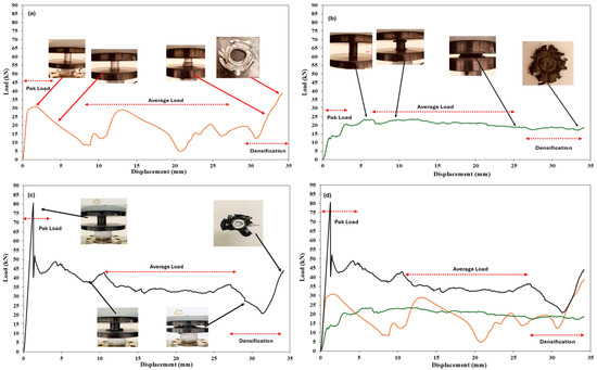
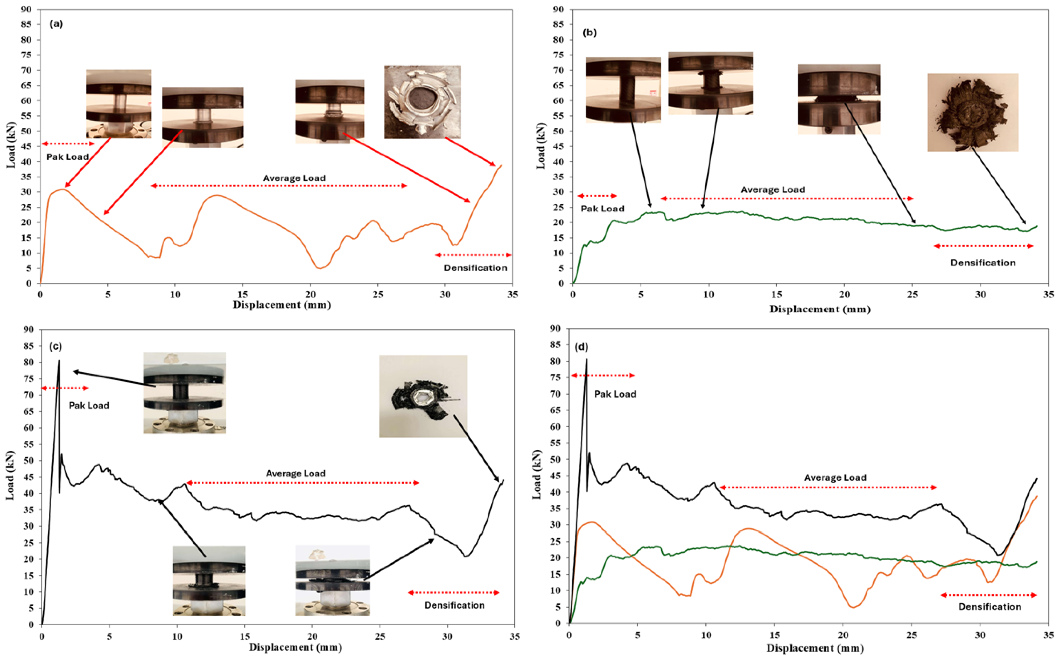
The load–displacement plots can be seen in Figure 4, where Figure 4a depicts the pure aluminium tube, Figure 4b displays the CFRP tube, and Figure 4c illustrates the aluminium/CFRP hybrid composite tube. The pure aluminium specimen, with an outer diameter of 30 mm and 45 mm long, was crushed at RT for comparative analysis with other specimens. The temperature of 25 °C was maintained for up to 13 h, followed by axial compression at a crushing speed of 5 mm/min. These parameters were selected because the optimal load-carrying capacity and EA were achieved for the S8 specimen. The peak load for the pure aluminium tube was measured at 30,840 N, which is approximately 2.6 times lower than that of S8. Similarly, axial crushing tests on the CFRP composite tube resulted in a Pmax of 23,385 N, which is nearly 3.45 times lower than that of S8. The aluminium tube exhibits higher loads and shows a typical progressive plastic buckling and folding crushing pattern. In contrast, the CFRP tube exhibits the lowest crushing load throughout the test due to its brittle nature. The fiber breakage, matrix cracking, and interfacial debonding contribute to a lower value of Pmax. Moreover, the hybrid composite outperforms both, maintaining the highest and most stable crushing performance. In a hybrid composite tube, the ductility of aluminium supports progressive folding, while the brittleness of CFRP provides stiffness, leading to a delay in delamination and local buckling.
Figure 4.
Load–displacement plot: (a) Pure aluminium specimen, (b) CFRP specimen, (c) specimen S8, and (d) comparative analysis.
It is evident from Figure 4d that there is an abrupt increase in crushing load values, known as the pre-crushing region, followed by a more gradual increase during the crushing process. At first, the crushing load increases sharply, and after reaching its peak, the slope immediately decreases and stays almost curved throughout. The peak values of crushing load for all samples occur below a range of 1–5 mm. The load displacement curve attains a peak value, and then it has a continuously declining slope throughout the crushing test. Such trends of the curve can be linked to the tube wall’s compressive shear fracture. The trends resemble the behavior of the composite tube described in earlier studies [6,38,39,40].
It was found that sample S8, which was crushed at RT with an isothermal holding time of 13 h and a crushing rate of 5 mm/min, exhibited a maximum crushing load of 80,650 N. When the speed was increased to 3.5 mm/min, the Pmax again increased to 64,630 N. This load decreased to 56,365 N when the temperature remained the same, but the speed was reduced to 2 mm/min. Therefore, at RT, crushing speed has a more significant impact than the other factors. The test results indicate that crushing speed is a key factor at RT because it directly controls the strain rate. Strain rate affects failure modes and how the material absorbs energy. Furthermore, when the temperature is around 63 °C and the isothermal holding time is 24 h, the crushing load ranges from 65,725 N to 58,845 N for crushing speeds of 5 mm/min and 2 mm/min, respectively. The crushing load decreases significantly at higher temperatures, but the effect of the crushing rate still influences the results. It is observed that at elevated temperatures, the structural integrity of the material was affected by thermal softening, leading to a lower crushing load compared to RT. However, even with thermal softening, the impact of crushing speed remains clear, as the load at 5 mm/min is higher than at 2 mm/min. This shows that higher temperature weakens the material, but a higher crushing speed provides relatively greater resistance than a slower speed. Therefore, both temperature and crushing speed are competing factors influencing higher loading capacity.
3.2. Initial Peak Force and Mean Crushing Force
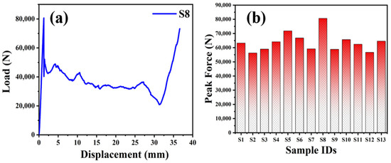
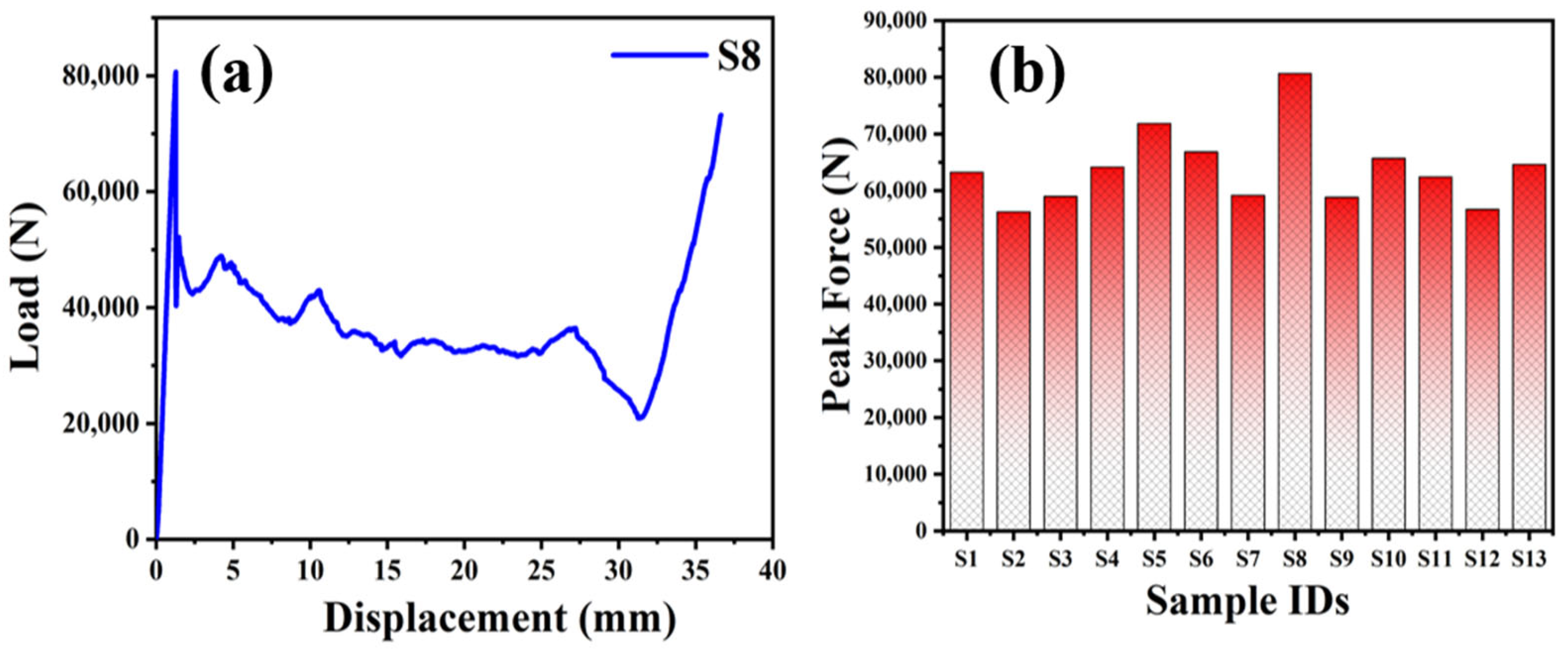
The load–displacement curve for the sample with the maximum crushing load is depicted in Figure 5. The plot indicates that the load gradually increases until reaching the initial peak, then decreases until complete crushing. The Pmax marks the first significant failure of the tube, which shifts to lower values with changes in temperature, speed, and processing time.
Figure 5.
Crushing test rests: (a) Load vs. displacement curve for S8 and initial peak load curves for all specimens and (b) Bar diagram for peak loads for all sample sets S1 to S13.
The values of Pmax and Pmean are summarized along with EA, SEA, and CFE in Table 5. The Table reviews all the crashworthiness characteristics obtained from the experimental work.
Table 5.
Tabulated data for Pmax, Pmean, EA, SEA, and CFE.
The Pmean ranges between 35,365.2 N and 29,644.2 N in the present study. The Pmean value indicates the ability to maintain structural integrity before material failure under crushing. The maximum Pmean value was observed for samples at RT, while at elevated temperatures, the Pmean decreases due to reduced material strength. A higher Pmean reflects better EA and structural stability, whereas a lower Pmean suggests premature failure of the materials. It is evident from Figure 5a that the maximum values of Pmax and Pmean, i.e., 80,650 N, 35,365.2 N, respectively, were recorded for the S8 sample. Furthermore, the values of Pmax and Pmean for other samples can be visualized from Figure 5b. It can be observed that maintaining a constant temperature of 63 °C and an isothermal holding time of 13 h results in crushing loads of 59,005 N at a crushing speed of 3.5 mm/min for samples S3. However, when the crushing speed increases to 5 mm/min, the crushing load rises to 71,840 N. At the highest temperature used in this experiment, 100 °C, keeping the sample at this temperature for 13 h causes the crushing load to increase with higher crushing speeds, 66,835 N at 5 mm/min and 64,160 N at 2 mm/min.
3.3. Energy Absorption Capacity
EA and SEA are two essential parameters for evaluating the crashworthiness of structural members under axial loading. A higher EA value represents the structure’s greater ability to absorb energy before failure, lowering the risk of catastrophic collapse. In this study, EA values range from 984.3 J (S3) to 1173.6 J (S8), with most specimens falling between 1000 and 1100 J. The EA data indicate consistent and stable energy dissipation. Meanwhile, SEA is equally essential for high-strength-to-weight-ratio applications. SEA values range from 54.1 J/g to 64.6 J/g, with most specimens falling between 57 and 62 J/g. A higher SEA suggests that the structure can absorb more energy per unit weight, which is crucial for lightweight applications. Among the tested specimens, S8 shows superior performance with an EA of 1173.6 J and an SEA of 64.8 J/g. Conversely, S3 records the lowest EA and SEA values, indicating poor crash performance. The remaining samples have EA and SEA values within a moderate range. The higher values of EA ensure that the material can dissipate a considerable amount of impact energy before experiencing sudden collapse. At the same time, higher SEA indicates the ability to absorb more energy with minimal material mass. This is particularly vital for engineering fields like automobile, aerospace, and defense, where lightweight design is essential.
3.4. Crushing Force Efficiency
The studied hybrid composite samples show values ranging from 0.44 to 0.59, indicating moderate to high stability after peak crushing. The CFE for most tube configurations ranges from 0.50 to 0.51, demonstrating the composite’s ability to withstand half of the peak load during axial crushing. However, some composite samples exhibit CFE values up to 0.58–0.59, reflecting enhanced structural integrity and significant energy absorption. Conversely, the lowest CFE observed was 0.44, suggesting an unexpected reduction in load-carrying capacity before reaching peak load, which is less desirable for axial load crashworthiness. The lowest CFE value is recorded for S8 (0.44) due to pronounced peak load (80,650 N) at low temperature, where material retains its strength and hardness, leading to limited progressive plastic deformation. Additionally, higher crushing speed increases strain rate, resulting in dislocation motion and cell wall folding. Hence, deformation becomes more localized, causing a large difference between Pmax and Pmean), thereby reducing the load uniformity and ultimately lowering the CFE. The higher CFE in composite tubes indicates that the structure maintains a consistent load-bearing capacity during axial crushing, which benefits energy-absorbing applications [41].
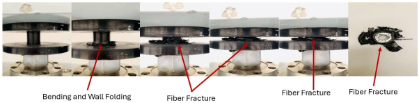
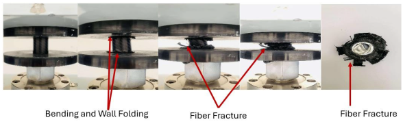
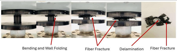
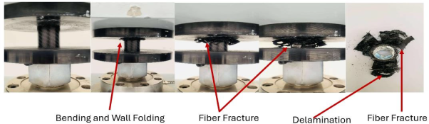
3.5. Failure Modes
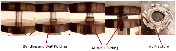
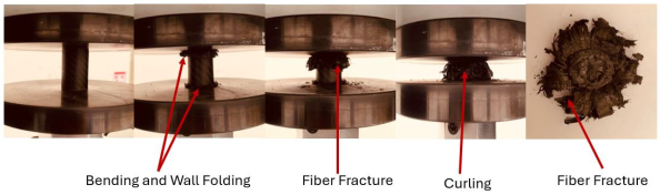
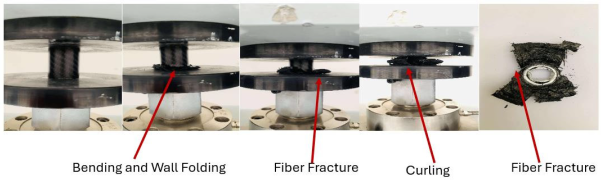
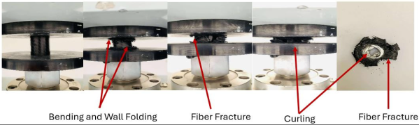
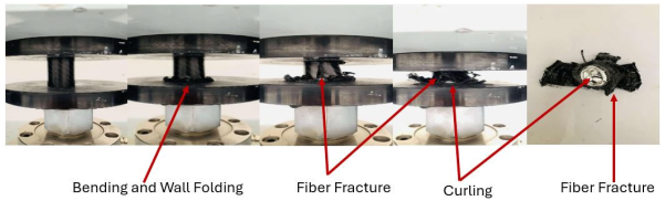
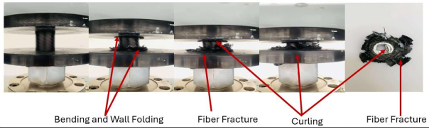
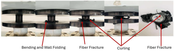
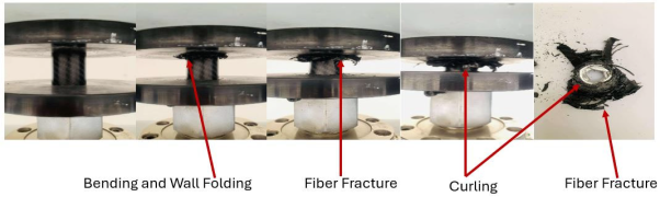
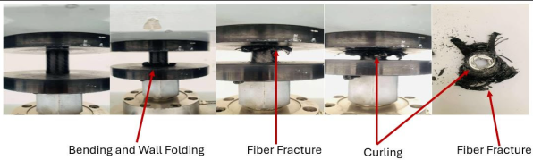
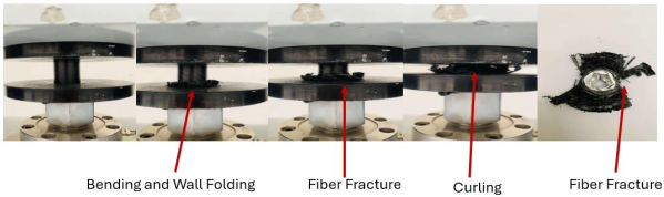
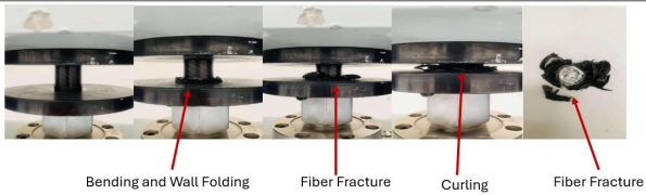
The failure mode of the hybrid composite tube specimen is summarized in Table 6. The data reveal the progressive failure of the tube through three main stages: initial end-crushing, unstable local buckling, and final collapse. When a tube is first subjected to a crushing load, microcracks form at the edges and spread rapidly as the load increases. As loading continues, local buckling occurs in the tube wall after reaching a critical peak force, causing fibers to splay outward and creating a petal-like fracture pattern. Later, matrix cracking develops in the composite, leading to fiber pullout, and ultimately, the tube collapses completely.
Table 6.
Failure modes of the hybrid composite tube specimens.
During the crushing test, it was observed that the failure of a tube depends upon parameters like temperature, isothermal holding time, and crushing speed. The influence of these parameters on crushing load has been examined using a 3D plot generated using Design Expert software and discussed in Section 4.
4. Predicted vs. Actual Plot
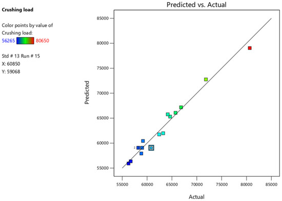
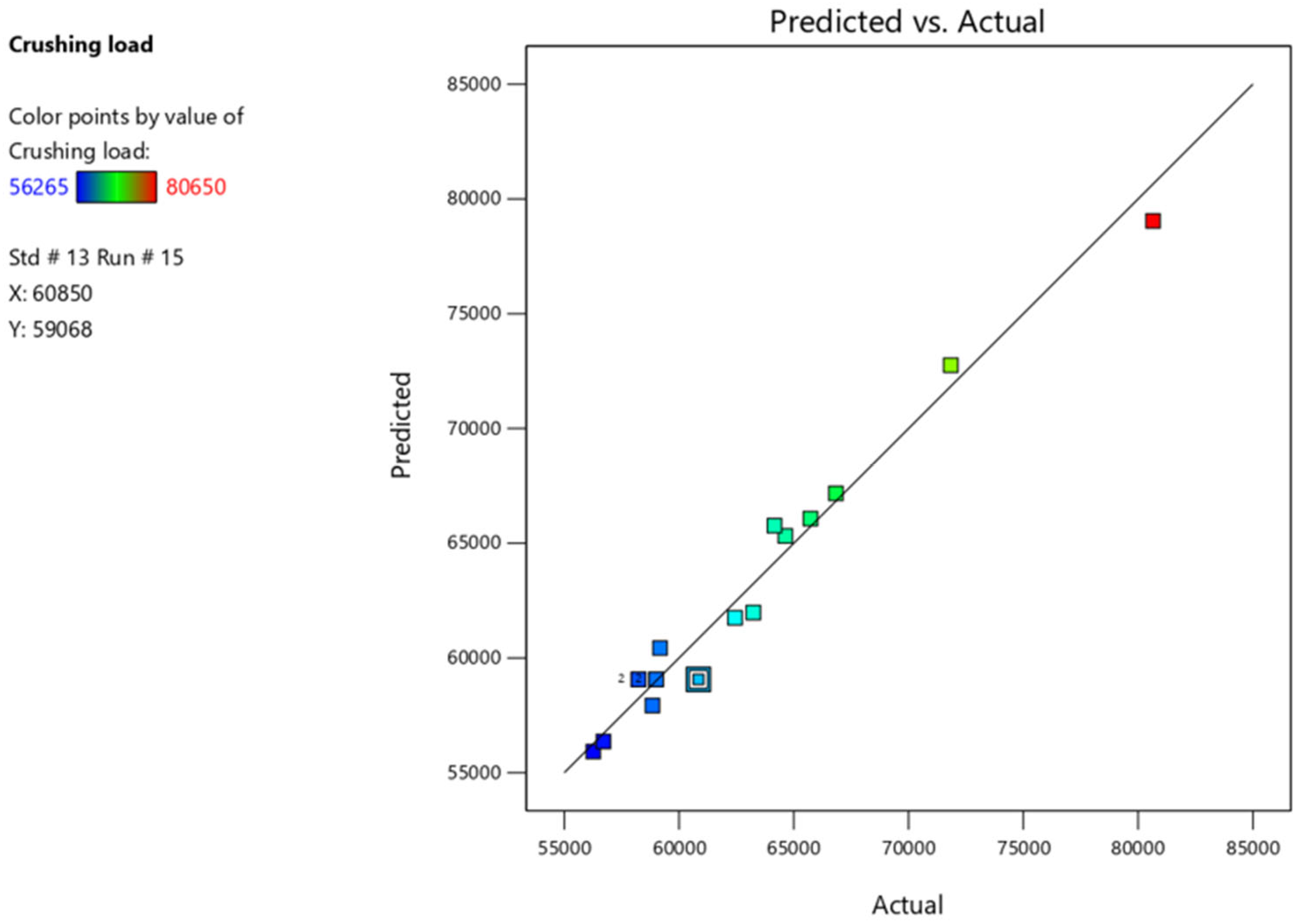
Figure 6 shows a Predicted vs. Actual plot generated using Design Expert software to analyze the crushing load performance of a predictive model. The actual crushing load is shown on the X-axis, while the Y-axis displays the predicted crushing load. A straight line indicates the ideal scenario where predicted and actual values match exactly, representing a perfect model fit. The crushing load is marked by a square symbol, with each symbol representing a specific experimental run. The blue square indicates lower values, the green square shows intermediate values, and the red square signifies the highest crushing loads.
Figure 6.
Predicted vs. Actual plot generated using Design Expert software.
Most data points are close to the straight line, indicating that the model is accurate, especially for lower and intermediate crushing load values. The plot’s trends show that the model fits well for almost all crushing load values.
4.1. ANOVA
ANOVA of the experiments is given in Table 7, which indicates whether the model is significant or not, lack of fit, R2 value, Adjusted R2, F-value, and p-value. The results of the RSM mode indicate that the model is highly reliable and adequate for predicting the response. The model is significant, demonstrating that the selected variables have a strong influence on the output, which is the crushing load. The insignificant lack of fit confirmed that the residual variation in experimental results is due to random error. The high R2 (0.9739) and adjusted R2 (0.9404) values indicate excellent predictive capability with minimal overfitting. Additionally, the high F-value (20.57) further supports the strong statistical influence of the model variables on output.
Table 7.
ANOVA of Experimental Result of RSM analysis.
The predicted values of yield % are determined by using the quadratic regression Equation (5), which is given below:
Crushing load = 59,068 − 505.62 A − 1279.37 B + 6133.75 C + 1163.75 AB − 5427.50 AC − 2062.50 BC + 3500.37 A2 − 197.13 B2 + 4409.13 C2
Equation (5) clearly indicates that output is highly influenced by process variables such as A, B, and C. The effect of the process variable on the output variable is interpreted in the subsections.
4.2. Effect of Independent Parameters on Crushing Behavior
It has been observed that working temperature, isothermal holding time, and crushing speed play a significant role in determining the crushing load.
4.2.1. Crushing Speed vs. Temperature Factor
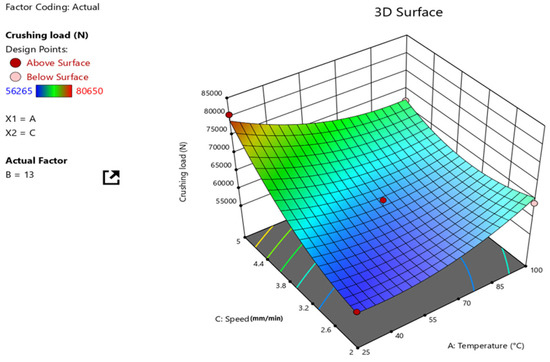
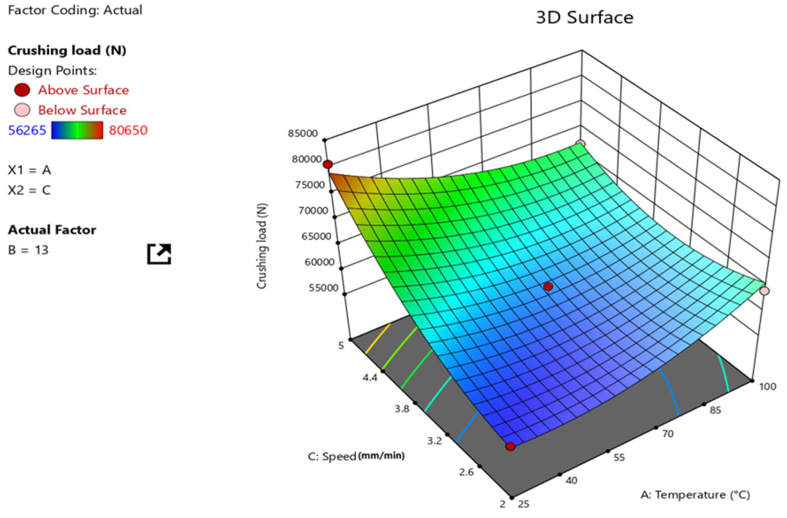
The role of two process parameters, specifically temperature (°C) and crushing speed (mm/min), on the crushing load (N) while keeping the third factor, isothermal holding time, constant, is illustrated using a 3D curve as depicted in Figure 7. The X-axis shows temperature (A) from 25 °C to 100 °C, and the Y-axis shows crushing speed (C) from about 2 mm/min to 5 mm/min, while the Z-axis indicates the crushing load, which ranges between 56,265 N and 80,650 N.
Figure 7.
A 3D surface plot generated using Design Expert software represents the influence of speed and temperature on crushing load.
The 3D plot is color-coded, with blue representing lower values, green indicating intermediate values, and red showing higher crushing loads. The solid red point on the 3D surface plot indicates actual experimental runs that are away from the best-fit line. It is observed that crushing load has a nonlinear interaction with temperature and speed, which increases at lower temperatures and higher speeds. The lowest crushing load is indicated by the blue color, showing that the structural integrity of the hybrid tube weakens at high temperatures and low speeds. From the curvature, it is clear that crushing load is affected by temperature and speed, enabling the identification of an optimal region for higher load-carrying capacity in structural applications.
4.2.2. Isothermal Holding Time vs. Crushing Speed Factor
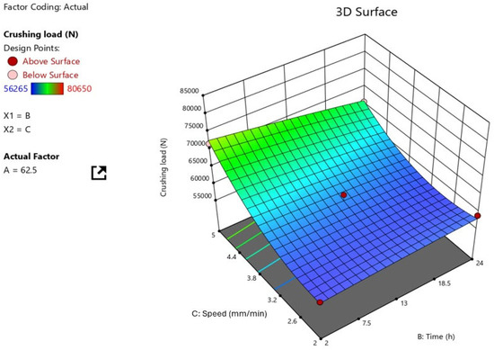
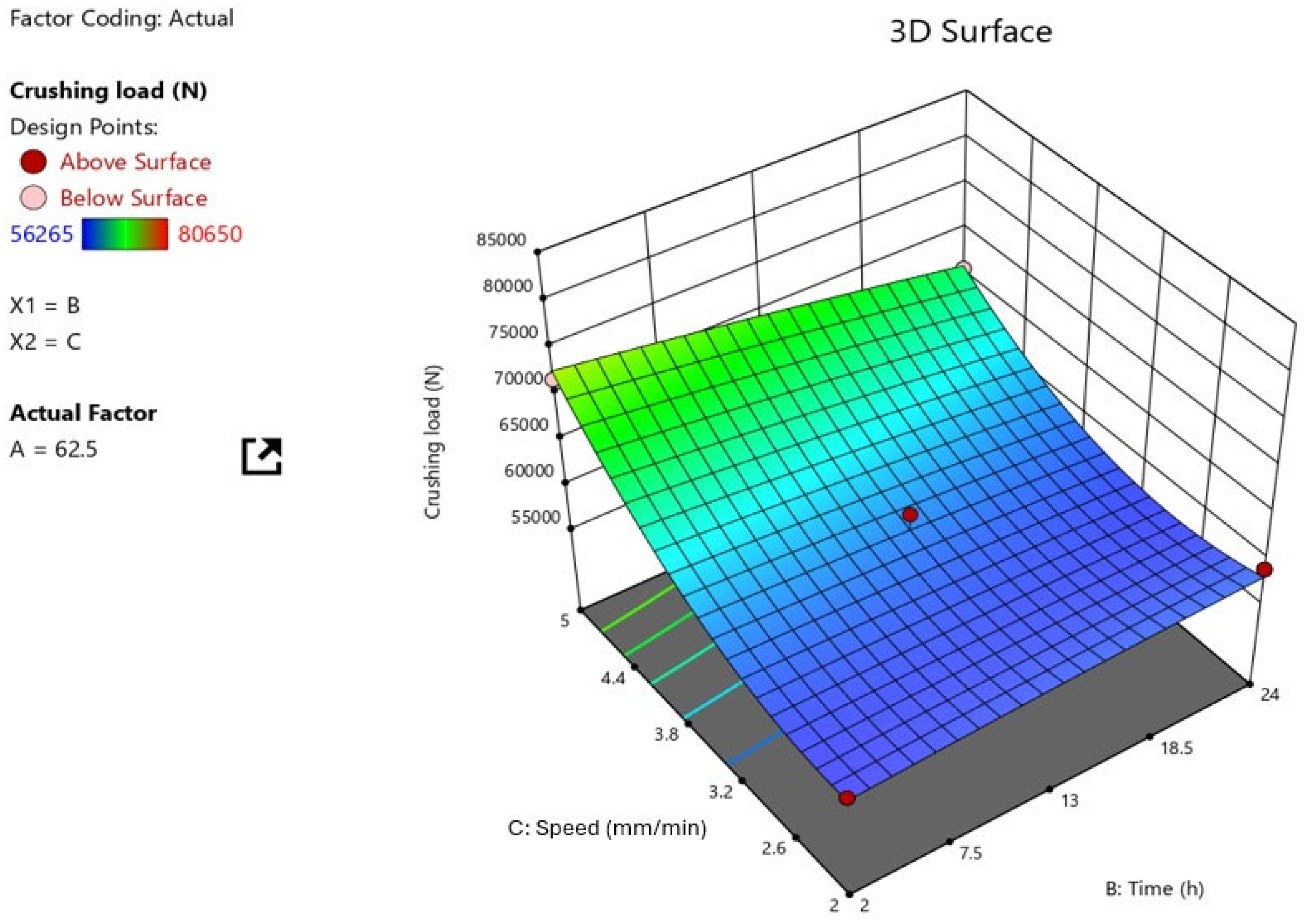
The 3D surface plot (Figure 8) shows the relationship between two process parameters, isothermal holding time and crushing speed, on the crushing load, with temperature (A) held constant at 62.5 °C. The X-axis displays time ranging from 2 h to 24 h, the Y-axis represents speed from 2 mm/min to 5 mm/min, and the Z-axis indicates the output function.
Figure 8.
A 3D surface plot generated using Design Expert software represents the influence of isothermal holding time and speed on crushing load.
The 3D curve surface clearly demonstrates that the crushing load increases with higher speeds and shorter exposure times. Shorter processing times and higher speeds enhance structural performance during crushing, while longer isothermal holding times and lower speeds lead to a significant decrease in crushing load. Therefore, an optimal parameter can be identified to achieve better structural performance under crushing loads.
4.2.3. Isothermal Holding Time vs. Temperature Factor
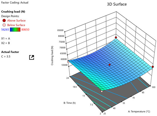
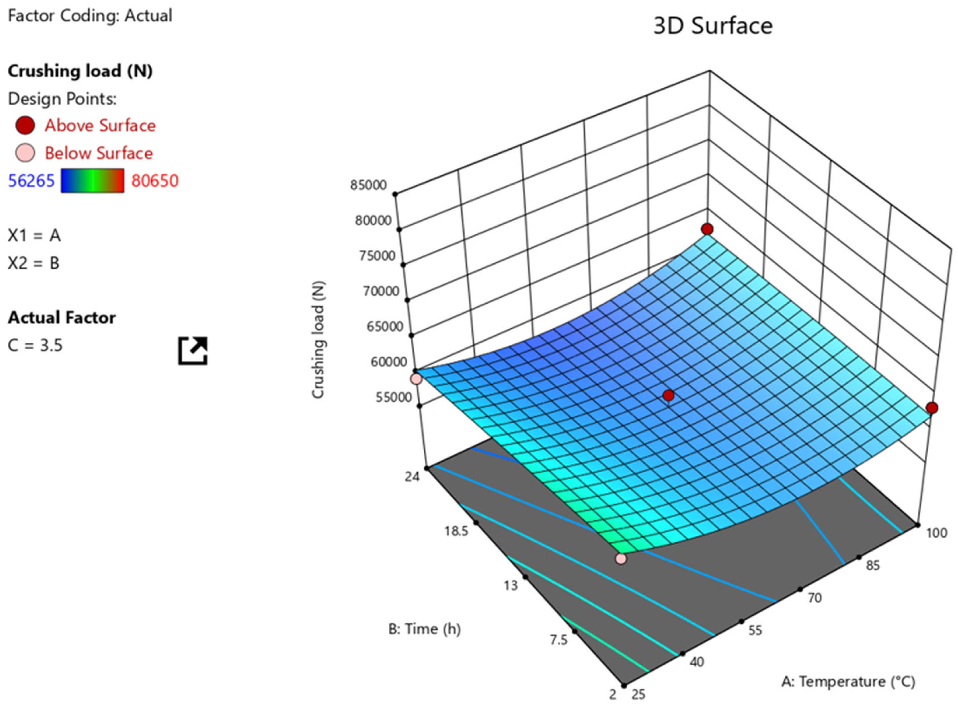
The 3D surface plot is created using Design Expert software to examine how temperature and isothermal holding time affect the crushing load while keeping the speed steady at 3.5 mm/min. The X-axis shows temperature, the Y-axis denotes time, and the Z-axis represents the crushing load. Figure 9 shows that crushing load increases as both isothermal holding time and temperature rise, but it appears to be lowest at low temperature and high time. However, the effect of these variables on crushing load is minor, not exponential, as the plot is nearly blue in color. The influence of crushing speed on the hybrid tube is found to be slight due to the sensitivity of fiber composite against strain rate compared to pure metals or alloys. Polymer composites are moderately strain-sensitive, resulting in a slight change in load-carrying capacity and EA during crushing.
Figure 9.
A 3D surface plot generated using Design Expert software represents the influence of time and temperature on crushing load.
The current study uses Design Expert software with RSM-based optimization for experimental design, offering significant advantages over traditional methods by systematically optimizing multiple variables with fewer trials, less time, lower costs, and reduced material use. Unlike standard approaches, RSM effectively captures interactions between factors and nonlinear effects, resulting in more precise predictive models. From an industrial standpoint, this analysis helps determine the best process parameters more efficiently, with greater reliability, lower costs, and higher accuracy.
5. Conclusions
The study analyzed the axial crash performance of aluminium/CFRP tubes using experimental RSM optimization methods. Crashworthiness properties were assessed through typical load–displacement plots and observed failure modes. The optimal parameters (working temperature, isothermal holding time, and crushing speed) were identified for maximum crushing loads across the tested specimens. The Pmax and EA of the tubes were found to be maximum for S8, at 80,650 N and 1173.6 J, respectively, whereas, the lowest Pmax was recorded for S2 (56,265 N), and the lowest EA was observed for S3 sample (984.3 J). Furthermore, the SEA capacity of the aluminium/CFRP tube was recorded the highest for S8 (64.8 J/g) and lowest for S3 (54.4 J/g). The data indicates that at higher temperatures, the crushing behavior of aluminium/CFRP is poor, resulting in lowered structural performance under crushing loads. The failure of composite tube was found mainly occurred in three modes: progressive end crushing, unstable local buckling, and unstable collapse. Besides the three parameters chosen in the current study, tube dimensions are also an essential factor. The crashworthiness of composite tubes can be further explored by considering tube dimensions as one of the variables in optimizing crashworthiness characteristics for higher crushing speeds.
Author Contributions
T.K., R.C., T.A.S. and H.J.: conceptualization, visualization, writing—original draft, experiment design: formal analysis. All authors have read and agreed to the published version of the manuscript.
Funding
This research received no external funding.
Data Availability Statement
The raw data supporting the conclusions of this article will be made available by the authors on request.
Acknowledgments
The authors would like to thank and sincerely appreciate the structure and materials lab, Department of Engineering Management, Faculty of Engineering, Prince Sultan University, Saudi Arabia, for providing the lab facility to conduct this study. The authors would like to acknowledge the support of Prince Sultan University, Riyadh, for paying the Article Processing Charge (APC) of this publication.
Conflicts of Interest
The authors declare no conflicts of interest.
References
- Ge, F.; Lin, Y.; Zhang, F.; Zhang, Z.; Wang, M. Crushing characteristics comparison between aluminum/CFRP and aluminum/CFRP/aluminum hybrid tubes. Polymers 2022, 14, 4034. [Google Scholar] [CrossRef] [Scilit]
- Mou, H.; Chen, Y.; Feng, Z.; Liu, H. Damage and energy absorption behavior of CFRP/aluminum hybrid open-section thin-walled columns subjected to quasi-static loading. Thin-Walled Struct. 2024, 197, 111593. [Google Scholar] [CrossRef] [Scilit]
- Sun, G.; Li, S.; Li, G.; Li, Q. On crashing behaviors of aluminium/CFRP tubes subjected to axial and oblique loading: An experimental study. Compos. B Eng. 2018, 145, 47–56. [Google Scholar] [CrossRef] [Scilit]
- Ataabadi, P.B.; Karagiozova, D.; Alves, M. Crushing and energy absorption mechanisms of carbon fiber-epoxy tubes under axial impact. Int. J. Impact Eng. 2019, 131, 174–189. [Google Scholar] [CrossRef] [Scilit]
- Zhou, G.; Sun, Q.; Fenner, J.; Li, D.; Zeng, D.; Su, X.; Peng, Y. Crushing behaviors of unidirectional carbon fiber reinforced plastic composites under dynamic bending and axial crushing loading. Int. J. Impact Eng. 2020, 140, 103539. [Google Scholar] [CrossRef] [Scilit]
- Zang, M.; Hu, Y.; Zhang, J.; Ye, W.; Zhao, M. Crashworthiness of CFRP/aluminum alloy hybrid tubes under quasi-static axial crushing. J. Mater. Res. Technol. 2020, 9, 7740–7753. [Google Scholar] [CrossRef] [Scilit]
- Shin, K.C.; Lee, J.J.; Kim, K.H.; Song, M.C.; Huh, J.S. Axial crush and bending collapse of an aluminum/GFRP hybrid square tube and its energy absorption capability. Compos. Struct. 2002, 57, 279–287. [Google Scholar] [CrossRef] [Scilit]
- Zhang, Z.; Liu, Q.; Fu, J.; Lu, Y. Parametric study on the crashworthiness of the Al/CFRP/GFRP hybrid tubes under quasi-static crushing. Thin-Walled Struct. 2023, 192, 111156. [Google Scholar] [CrossRef] [Scilit]
- Abu Bakar, M.S.; Salit, M.S.; Mohamad Yusoff, M.Z.; Zainudin, E.S.; Ya, H.H. The crashworthiness performance of stacking sequence on filament wound hybrid composite energy absorption tube subjected to quasi-static compression load. J. Mater. Res. Technol. 2020, 9, 654–666. [Google Scholar] [CrossRef] [Scilit]
- Lee, K.S.; Hwang, W.C.; Yang, I.Y. Crashworthiness of aluminum/CFRP hybrid member with various stacking condition. Int. Conf. Smart Mater. Nanotechnol. Eng. 2007, 6423, 642346. [Google Scholar] [CrossRef] [Scilit]
- Junaedi, H.; Khan, T.; Sebaey, T. Characteristics of Carbon-Fiber-Reinforced Polymer Face Sheet and Glass-Fiber-Reinforced Rigid Polyurethane Foam Sandwich Structures under Flexural and Compression Tests. Materials 2023, 16, 5101. [Google Scholar] [CrossRef] [Scilit] [PubMed]
- Hanssen, A.G.; Langseth, M.; Hopperstad, O.S. Static and dynamic crushing of square aluminium extrusions with aluminium foam filler. Int. J. Impact Eng. 2000, 24, 347–383. [Google Scholar] [CrossRef] [Scilit]
- Shen, Y.; Wu, Z.; Hu, X. Effect of reinforcement layer number on energy absorption of aluminum-CFRP hybrid square tubes under axial loading: Experimental and numerical study. Thin-Walled Struct. 2020, 155, 106935. [Google Scholar] [CrossRef] [Scilit]
- Khan, T.; Alshahrani, H.; Abd-Elaziem, W.; Umarfarooq, M.A.; Sebaey, T.A. Quasi-static axial crushing of multi-tubular foam-filled carbon fiber reinforced composite structures. Polym. Compos. 2023, 44, 7843–7854. [Google Scholar] [CrossRef] [Scilit]
- Palanivelu, S.; Van Paepegem, W.; Degrieck, J.; Vantomme, J.; Kakogiannis, D.; Van Ackeren, J.; Van Hemelrijck, D.; Wastiels, J. Crushing and energy absorption performance of different geometrical shapes of small-scale glass/polyester composite tubes under quasi-static loading conditions. Compos. Struct. 2011, 93, 992–1007. [Google Scholar] [CrossRef] [Scilit]
- Alshahrani, H.; Sebaey, T.A. Bearing Properties of CFRP Composite Laminates Containing Spread-Tow Thin-Plies. Polymers 2022, 14, 2076. [Google Scholar] [CrossRef] [Scilit]
- Tang, E.; Zhang, X.; Han, Y. Experimental research on damage characteristics of CFRP/aluminum foam sandwich structure subjected to high velocity impact. J. Mater. Res. Technol. 2019, 8, 4620–4630. [Google Scholar] [CrossRef] [Scilit]
- Liu, Q.; Mo, Z.; Wu, Y.; Ma, J.; Pong Tsui, G.C.; Hui, D. Crush response of CFRP square tube filled with aluminum honeycomb. Compos. B Eng. 2016, 98, 406–414. [Google Scholar] [CrossRef] [Scilit]
- Demir, S.; Ersoy, N.; Engül, M.C. Axial quasi-static crushing of composite tubes: An investigation on the influence of the modeling techniques. J. Reinf. Plast. Compos. 2023, 44, 17–35. [Google Scholar] [CrossRef] [Scilit]
- Liu, Q.; Xu, X.; Ma, J.; Wang, J.; Shi, Y.; Hui, D. Lateral crushing and bending responses of CFRP square tube filled with aluminum honeycomb. Compos. B Eng. 2017, 118, 104–115. [Google Scholar] [CrossRef] [Scilit]
- Xiao, Z.; Mo, F.; Zeng, D.; Yang, C. Experimental and numerical study of hat-shaped CFRP structures under quasi-static axial crushing. Compos. Struct. 2020, 249, 112465. [Google Scholar] [CrossRef] [Scilit]
- Asyraf, M.R.M.; Ishak, M.R.; Syamsir, A.; Nurazzi, N.M.; Sabaruddin, F.A.; Shazleen, S.S.; Norrrahim, M.N.F.; Rafidah, M.; Ilyas, R.A.; Abd Rashid, M.Z.; et al. Mechanical Properties of Oil Palm Fibre-Reinforced Polymer Composites: A Review. J. Mater. Res. Technol. 2022, 17, 33–65. [Google Scholar] [CrossRef] [Scilit]
- Afzal, A.; Bangash, M.K.; Hafeez, A.; Shaker, K. Aging Effects on the Mechanical Performance of Carbon Fiber-Reinforced Composites. Int. J. Polym. Sci. 2023, 2023, 4379307. [Google Scholar] [CrossRef] [Scilit]
- Kumar, P.; Shunmugasundaram, M.; Sivasankar, S.; Baig, M.A.A.; PonrajSankar, L. An experimental analysis on the transverse crushing behaviour of Nano-filler reinforced composite cylindrical tubular elements. IOP Conf. Ser. Mater. Sci. Eng. 2021, 1057, 012018. [Google Scholar] [CrossRef] [Scilit]
- Samim, S.; Mahdi, E.; Mustapha, M.; Rusli, A.; Shakoor, R.A. Quasi-static axial crushing investigation of filament-wound eco-friendly energy-absorbing glass fiber and jute fiber composite structures. J. Mater. Res. Technol. 2024, 30, 6389–6403. [Google Scholar] [CrossRef] [Scilit]
- Khan, R.A.; Mahdi, E. Effect of trigger mechanisms on the quasi-static axial crushing behavior of glass epoxy/polyvinyl chloride hybrid composite tubes. Thin-Walled Struct. 2023, 182, 110306. [Google Scholar] [CrossRef] [Scilit]
- Sampath, V.; Rao, C.L.; Reddy, S. Energy Absorption of Foam Filled Aluminum Tubes under Dynamic Bending. Procedia Manuf. 2017, 7, 225–233. [Google Scholar] [CrossRef] [Scilit]
- Tezara, C.; Hadi, A.E.; Siregar, J.P.; Muhamad, Z.; Hamdan, M.H.M.; Oumer, A.N.; Jaafar, J.; Irawan, A.P.; Rihayat, T.; Fitriyana, D.F. The Effect of Hybridisation on Mechanical Properties and Water Absorption Behaviour of Woven Jute/Ramie Reinforced Epoxy Composites. Polymers 2021, 13, 2964. [Google Scholar] [CrossRef] [Scilit]
- Akhtar, M.; Shahzadi, S.; Arshad, M.; Akhtar, T.; Saeed Ashraf Janjua, M.R. Metal oxide-polymer hybrid composites: A comprehensive review on synthesis and multifunctional applications. RSC Adv. 2025, 15, 18173–18208. [Google Scholar] [CrossRef] [Scilit]
- Zhu, G.; Liao, J.; Sun, G.; Li, Q. Comparative study on metal/CFRP hybrid structures under static and dynamic loading. Int. J. Impact Eng. 2020, 141, 103509. [Google Scholar] [CrossRef] [Scilit]
- Pawlak, A.M.; Górny, T.; Dopierała, Ł.; Paczos, P. The Use of CFRP for Structural Reinforcement—Literature Review. Metals 2022, 12, 1470. [Google Scholar] [CrossRef] [Scilit]
- Xiao, Y.; Wen, X.; Lu, S.; Liang, D.; Hu, H.; Long, H.; Xie, W. Analysis of Factors Affecting Crashworthiness of CFRP Thin-Walled Square Tubes Filled with Gradient Aluminum Foam. J. Mater. Eng. Perform. 2024, 33, 7334–7344. [Google Scholar] [CrossRef] [Scilit]
- He, W.; Yao, L.; Meng, X.; Sun, G.; Xie, D.; Liu, J. Effect of structural parameters on low-velocity impact behavior of aluminum honeycomb sandwich structures with CFRP face sheets. Thin-Walled Struct. 2019, 137, 411–432. [Google Scholar] [CrossRef] [Scilit]
- Ueda, M.; Tasaki, Y.; Kawamura, C.; Nishida, K.; Honda, M.; Hattori, K.; Miyanaga, T.; Sugiyama, T. Estimation of axial compressive strength of unidirectional carbon fiber reinforced plastic considering local fiber kinking. Compos. Part C Open Access 2021, 6, 100180. [Google Scholar] [CrossRef] [Scilit]
- Chamola, R.; Khan, M.F.; Raj, A.; Verma, M.; Jain, S. Response surface methodology based optimization of in situ transesterification of dry algae with methanol, H2SO4 and NaOH. Fuel 2019, 239, 511–520. [Google Scholar] [CrossRef] [Scilit]
- Cetin, E.; Baykasoğlu, A.; Erdin, M.E.; Baykasoğlu, C. Experimental investigation of the axial crushing behavior of aluminum/CFRP hybrid tubes with circular-hole triggering mechanism. Thin-Walled Struct. 2022, 182, 110321. [Google Scholar] [CrossRef] [Scilit]
- Yao, R.-Y.; Zhang, B.; Yin, G.-S.; Zhao, Z.-Y. Energy absorption behaviors of foam-filled holed tube subjected to axial crushing: Experimental and theoretical investigations. Mech. Adv. Mater. Struct. 2020, 28, 2501–2514. [Google Scholar] [CrossRef] [Scilit]
- Kaman, M.O.; Erdem, S.; Albayrak, M.; Gur, M.; Asan, A.M.; Eroglu, M.; Bozkurt, I. Experimental and Numerical Investigation of Axial Crushing Behavior of Hybrid Sandwich Pipes. Proc. Inst. Mech. Eng. Part L J. Mater. Des. Appl. 2026. [Google Scholar] [CrossRef] [Scilit]
- Sebaey, T.A.; Junaedi, H.; Alshahrani, H.; Alyamani, R.; Akkad, K. Effect of thermal aging on the crashworthiness of foam-filled CFRP composite tubes under lateral compression. J. Mater. Res. Technol. 2023, 23, 1–12. [Google Scholar] [CrossRef] [Scilit]
- Khan, T.; Junaedi, H.; Sebaey, T.A. Mechanical behavior of micro-fiber-reinforced foam-filled carbon fiber composite tubes under axial compression loading. Polym. Compos. 2025, 46, 12174–12183. [Google Scholar] [CrossRef] [Scilit]
- Zha, Y.B.; Wang, S.; Ma, Q.H.; Zhang, H.; Xue, H.; Zhou, T.J. Study on the axial impact of Al–CFRP thin-walled tubes with induced design. Polym. Compos. 2022, 43, 4660–4686. [Google Scholar] [CrossRef] [Scilit]

Disclaimer/Publisher’s Note: The statements, opinions and data contained in all publications are solely those of the individual author(s) and contributor(s) and not of MDPI and/or the editor(s). MDPI and/or the editor(s) disclaim responsibility for any injury to people or property resulting from any ideas, methods, instructions or products referred to in the content. |
© 2026 by the authors. Licensee MDPI, Basel, Switzerland. This article is an open access article distributed under the terms and conditions of the Creative Commons Attribution (CC BY) license.