Abstract
Additive manufacturing technologies, well known as three-dimensional printing (3DP) technologies, have been applied in many industrial fields, including aerospace, automobiles, shipbuilding, civil engineering and nuclear power. However, despite the high material utilization and the ability to rapidly construct complex shaped structures of 3D printing technologies, the application of additive manufacturing technologies in railway track infrastructure is still at the exploratory stage. This paper reviews the state-of-the-art research of additive manufacturing technologies related the railway track infrastructure and discusses the challenges and prospects of 3D printing technology in this area. The insights will not only help the development of 3D printing technologies into railway engineering but also enable smarter railway track component design and improve track performance and inspection strategies.
1. Introduction
The railway industry is a traditional part of civil engineering. Since the first railway line was built in 1825, the railway system has been one of the most important transportation methods in every country around the world [1]. The railway includes tram, metro, intercity, freight railway and passenger railways (normal-speed and high-speed). According to the type of supporting layer, railway systems can be classified into ballasted track and ballast-less track (slab track) [2]. The ballasted railway track is usually composed of the rails (including stock rails, closure rails, wing rails and guardrails in turnout area), fastener system, sleepers (bears in crossing area), ballasted bed (including ballast layer and sub-ballast layer) and subgrade [3]. In slab track railway systems, the concrete track slab serves as a substitution for the sleepers and the ballasted layer to support the rails [4,5]. Ballasted tracks are more widely used than concrete slab tracks because of their easy maintenance and low construction cost. Concrete slab tracks are adopted in high-speed railway lines for high track stiffness and good ride comfort [5]. The railway track system also includes special components for particular issues, for example, retaining walls in bridge railways [6], geogrids for locking ballast particles [7], soundproof walls for noise reduction [8] and sand-blocking fences for preventing the sand from damaging the track components [9]. The railway tracks (including ballasted track and slab track) are an assembly of many structures, working collaboratively to keep the rail gauge and rail elevation.
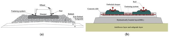
The components of ballasted track and concrete slab track systems are present in Figure 1. Railway infrastructure can redistribute the dynamic loads induced by passing trains, prevent rails from deforming and moving, reduce noise and improve ride comfort [2]. The stress inside railway infrastructure is greatest near the wheel–rail interface and is redistributed to a lower value on the rail-to-sleeper (including embedded sleeper in slab track) contact surface with a larger contact area. The dynamic loads are also redistributed at the sleeper to ballasted layer, ballasted layer to subgrade, embedded sleeper to concrete slab and concrete slab to subgrade interfaces. In order to serve in safe and comfortable conditions, railway infrastructure is designed with strong parts (e.g., rails and sleepers) on the top and weak parts (e.g., ballasted layer with crushed rocks and subgrade) on the sublayer. This can be observed from the strength of materials used for the components. For example, the mechanical strengths of rail (steel), sleeper (concrete, timber, composite and steel), ballasted layer (crushed rock particles) and subgrade (soil) are from high to low, accordingly.
Figure 1.
Schematic view of (a) ballasted track; (b) concrete slab track (reproduced from [5]).
In recent decades, ultra-high-speed and heavier-haul railways have been developed in many countries (such as China, France and Japan) [10]. The rolling stocks with higher speed and larger mass can induce dynamic axle load with greater magnitude and higher frequency than in the past, which puts forward stricter requirements on the reliability of the railway systems than before. Most recently, the railway turnout system’s safety and reliability are becoming a major problem due to the aforementioned trends. The failure and deterioration of the railway infrastructures caused by the train passing, the environmental variation, and the deterioration of ballasted layers is more frequent than before. The typical components of the railway turnout system, such as rail pads, concrete bearers and ballasted beds, were designed to support the rolling stocks with normal speed and mass. Those components may fail when subjected to the current complex load, which results in a great risk to comfort and safety. In extreme cases, it may lead to safety incidents such as derailment and roll-over. The performance of conventional railway components is limited. Also, the severe loads can result in wheel and rail wear and difficulty in track detection. Thus, it is of great significance to design components with better energy absorption and vibration reduction performance given the current railway serving load. Many researchers have phased in new technologies to improve conventional railway track systems, such as machine learning [11], additive manufacturing [12], 3D scanning [13,14], topology optimization [15], etc.
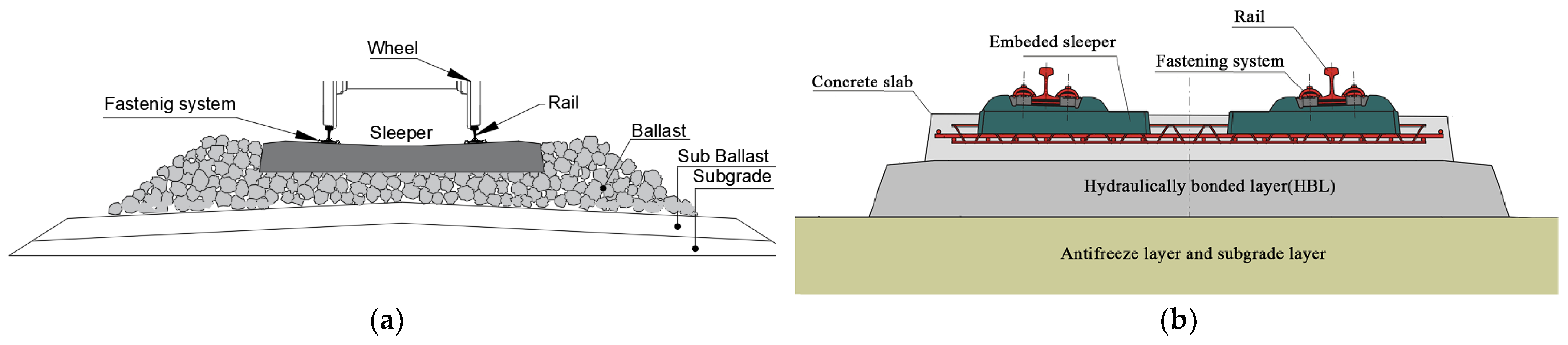
Additive manufacturing technology, well known as 3D printing, is based on digital model files using layer-by-layer addition of metal powders or plastic materials to fabricate three-dimensional objects [16,17]. According to ASTM Standard F2792 [18], the 3D printing technologies can be classified by the processing similarities into seven groups: binder jetting, directed energy deposition, material extrusion, material jetting, powder bed fusion, sheet lamination and vat photopolymerization. Their main principles are layered manufacturing and layered overlaying. As a product of the fusion of machinery, materials, computer science and other technologies, additive manufacturing technology has made direct manufacturing driven by digital models a reality and has become a landmark technology for the new industrial revolution [19,20]. Compared with traditional manufacturing technology, 3D printing enables the integration of complex structures and mould-free manufacturing, personalized customization, multi-components and multi-materials, while reducing material waste [21]. As reported in [22], 3D printing technologies have been widely used in many fields including industrial machines, consumer products/electronics, aerospace, medical/dental, academic, government/military, architectural and etc. Figure 2 presents the proportions of 3D printing technologies adopted in different fields. The government and academic institutions have shown growing interest in 3D printing technologies for the ability to produce complex objects and the increasing 3D printing market all over the world [23]. In the last few decades, many railway institutions and researchers started to combine railway industry with 3D printing technologies. For example, Germany Siemens Mobility has established the Alliance for Availability system and plan to 3D print spare parts for railway vehicles; Mobility Goes Additive (MGA) has printed the first safety component for the railway sectors; the China Academy of Railway Sciences (CARS) established the 3D printing lab in 2016 for phasing 3D printing into track structures.
Figure 2.
Industrial usage of 3D printing technologies.
This paper focuses on additive manufacturing technology (3D printing) application in railway track infrastructure components. The state-of-art review has summarised the 3D printing technology about railway track research in the following contents, by presenting the relevant research on the rails, fasteners, rail pads, sleepers(bearers), supporting layers (ballasted bed and concrete track slab) and special components. The challenges of adopting additive manufacturing to produce railway infrastructures are discussed. The future prospects of 3D printing technologies in railway infrastructure component design and improving track detection and maintenance are concluded. The insight can promote the development of additive manufacturing technology in railway engineering. Furthermore, this will help to put forward new solutions for addressing some railway problems, such as railway track stiffness issues in transition zones and rail/wheel wear problems.
2. Additive Manufacturing in Railway Components
The railway track infrastructure is a complex system composed of multiple components. Each component must have sufficient strength, elasticity and durability to provide adequate lateral and longitudinal resistance and proper track stiffness. In this section, the research about each component related to additive manufacturing technology is reviewed.
2.1. Rails
The rail directly supports the rolling stock and guides the direction of passing trains. The dynamic loads induced by the moving vehicles can result in rail corrugation, wear, rolling contact fatigue (RCF) issues and surface damage [24,25,26]. With the rapid development of high-speed and heavy-haul railway lines, the risk of rail damage and failure is increasing [27,28]. In order to improve the rail wear and RCF resistance, the select laser melting(SLM) additive manufacturing technology, also called laser melting, have been adopted by many researchers to produce an enhanced layer on the rail top surfaces [29].
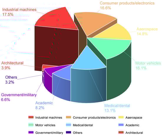
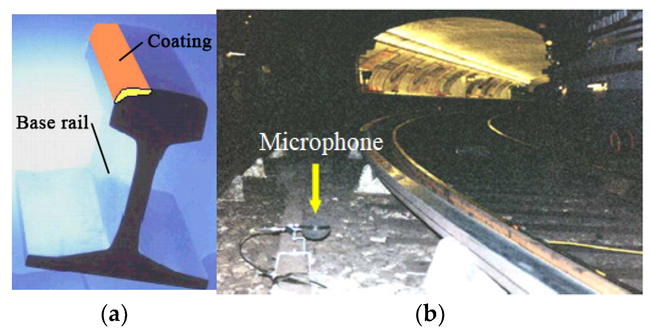
The European InfraStar project first used the laser cladding technology to produce a reinforced layer on the railhead area [30,31,32,33], as shown in Figure 3a. The noise measurements of the enhanced bi-material rails with different Duroc materials were then carried out in Malmbanan (Figure 3b). This approach can increase rolling contact fatigue performance, shorten the maintenance intervals and reduce the noise caused by wheel–rail interaction [30]. Compared with past repairing technology, the additive manufacturing not only can repair the local real damage but also can improve the rail performance and prolong rail service life [34].
Figure 3.
European InfraStar project. (a) the two-material rail; (b) noise measurements at Malmbanan. (Both reproduced from [30]).
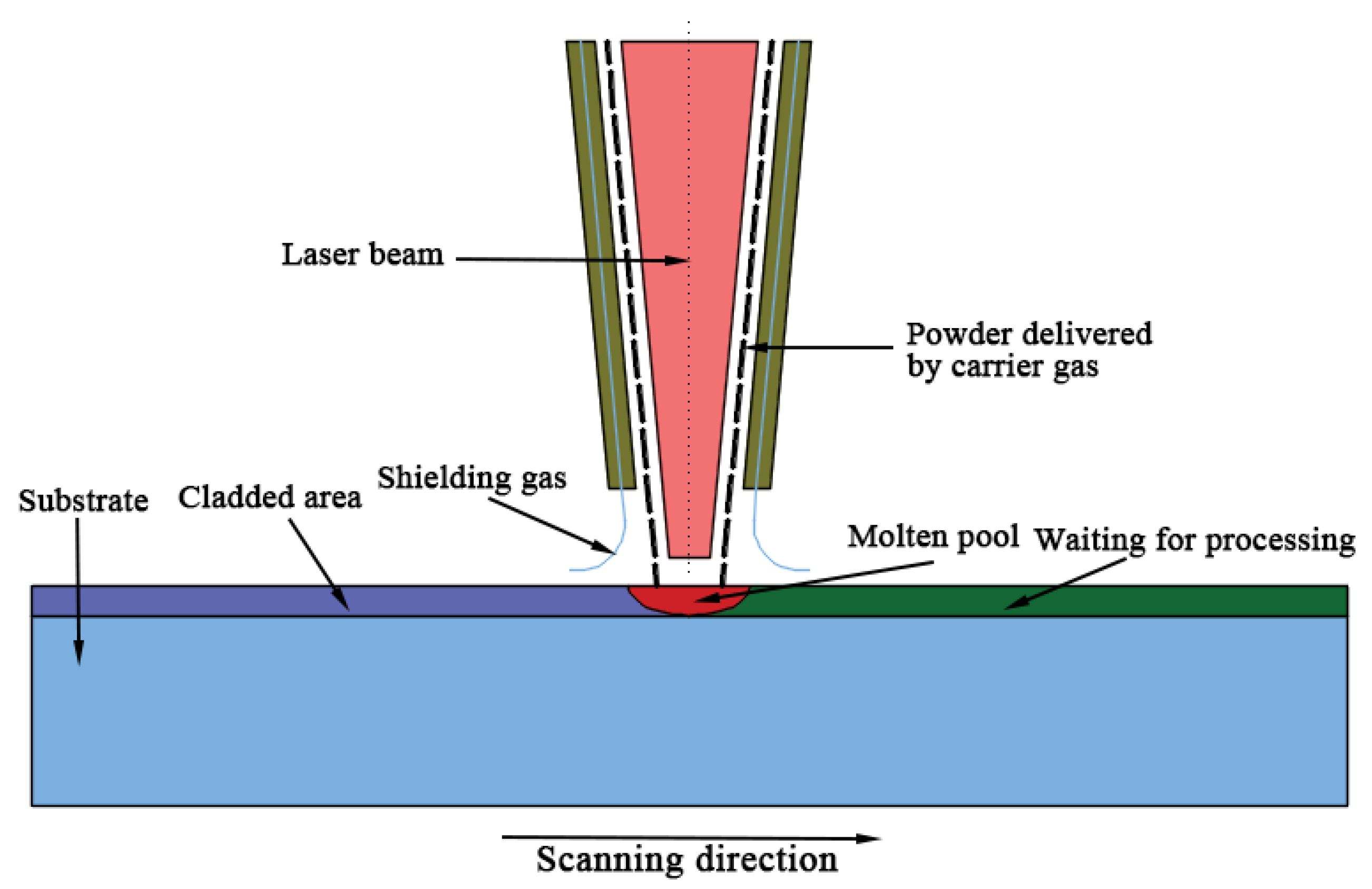
Figure 4 shows the schematic of the laser cladding process. The laser cladding process includes: (1) a molten pool is built on the substrate (railhead) using laser beam; (2) metallic powders are delivered to the molten pool area by carrier gas; (3) the metallic powders are molten, fused with the base substrate in molten pool and cooled down; (4) the nozzles and laser beam are moved through a certain routine controlled by the computer. The processes are repeated [35,36].
Figure 4.
Schematic diagram of laser cladding process.
The mechanical properties (e.g., tensile strength and residual stress) of laser cladded rail is affected by the material type, the granularity of alloy powders and 3D printing processes (e.g., scanning pattern, designed angle, printing speed and laser power) [37,38]. The laser cladding can be used to enhance many types of rails, including hyper-eutectoid rail, U71Mn rail (GB), R400HT(EN), HE400(EN), R260(EN), R200(EN). The cladded layer can be classified into Fe-based, Ni-based, Co-based and other types according to the base material type. The summary of cladding materials for enhancing rails and the related 3D printing process are listed in Table 1. The influence of laser cladding on the rail has not been fully understood. However, it can be concluded from the present research that: (1) increasing laser power can help create fine cladding grain [39,40]. (2)The size of cladded layer is significantly affected by the powder feeding speed [41,42]. (3) The grain size and morphology of the cladding layer are determined by the thermal history [38,43]. The high G/R, the ratio of temperature gradient at the solid-liquid interface (G) to thermal gradient cooling rate(R), can promote the occurrence of columnar crystal [24]. The low G/R can help the generation of dendrite crystal [44,45,46]. (4) Angular microstructures can provide higher hardness than the leaf-like microstructures [47]. (5) Laser cladding can increase the hardness of rail. The hardness increases to the max at around 0.25 mm along the depth direction in the cladded layer and then decreases to the same as the substrate rail [48]. (6) The hardness of cladded rail is not sensitive to small changes in laser cladding processes [49]. (7) The higher content of MxCy phases and martensitic structure can make the rail cladded layer harder [50]. (8) Increasing the hardness of rail can prevent wear and crack occurrence on the rail-wheel interface [51,52]. (9) The thermal processing(heating and cooling) in laser cladding can produce residual stress inside the rail, which will damage rail fatigue and anti-cracking performance [53,54,55]. (10) Post-heat treatment to the cladding layer can improve ductility and elongation [56]. (11) The bending strength of the cladding layer is better than the substrate rail [28], and the formation of fine pearlite microstructures can benefit the bending behaviour [50,57]. (12) The fatigue performance of cladding layers is determined by the properties of the heat affected zone. The laser cladded layer has a uniform deformation when exposed to dynamic load, which can restrain the crack and rail surface failure [48,58,59,60]. (13) Adding reinforcement materials into the cladding layer can help improve the mechanical properties of the rail [61]. (14) Optimization of additive manufacturing processes, such as a magnetic approach, WAAM and HF-WAAM, can help improve the yield strength and ultimate tensile strength of rails [62,63,64,65].
Table 1.
Materials used in laser cladding repaired and enhanced rail.
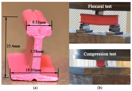
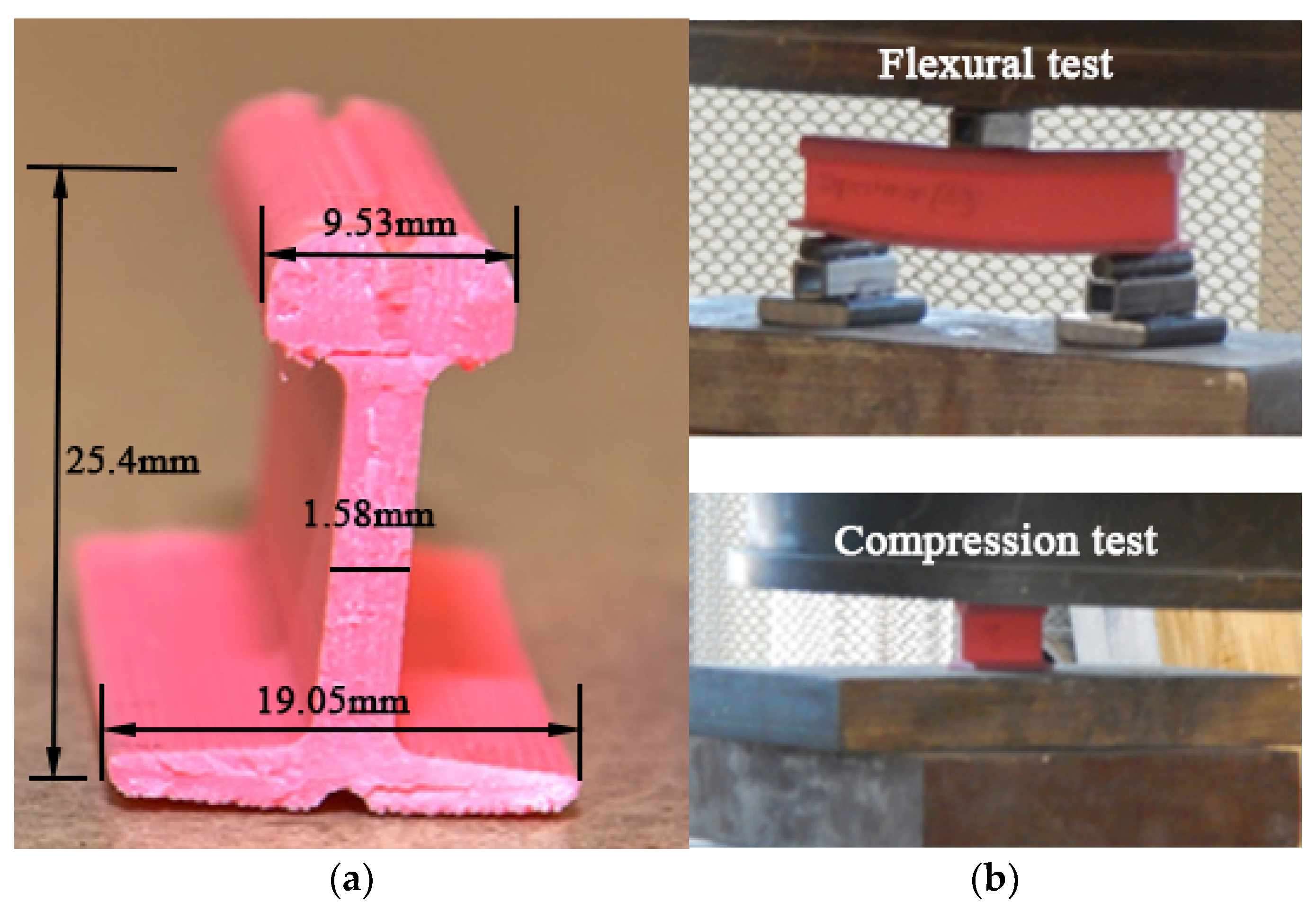
Ref. [73] adopted the fused deposition modelling method to fabricate composite rails for micro-people movers (MPM) and evaluated the failure modes of the printed rails with different polylactide fibre contents (material density) under static load tests. The size of the printed rail and the test settings are present in Figure 5. The results indicate that the bearing capacity of the 3D printed rails is determined by the fibre contents and the printing direction, and the failure modes change from material-control to structure-control as the fibre contents increase from 20% to 100%.
Figure 5.
Prototyping rail for micro-people movers using additive manufacturing: (a) 3D printed composite rail; (b) compression and flexural tests. Both have been reproduced from [73].
2.2. Fasteners
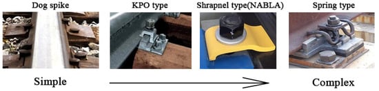
The railway fastener system helps to fix rails on sleepers or track slabs and provides elasticity for the rails [74,75]. There are many types of fastener system all over the world, such as 102 and 8 K types from Japan, Nabla from French [76], RST and VOSSLOH 300 from German [77,78], Pandrol series from the UK [79] and WJ series from China [80]. Their components and structures are different, but they can be regarded as comprising three parts: withholding parts (e.g., clips, clamps), jointing parts (e.g., dog spikes, screw spikes and dowels) and elastic pads (rail pads). The railway fastener systems develop from simple shapes to complex structures, as shown in Figure 6. The fastener systems can be classified into rigid type (Dog spike and KPO type) and elastic type (Shrapnel type and Spring type). The elastic fasteners provide greater elasticity, better fatigue performance and higher corrosion resistance than rigid type fasteners and have become the most widely used fastener systems in current railway lines.
Figure 6.
The change of railway fastener systems.
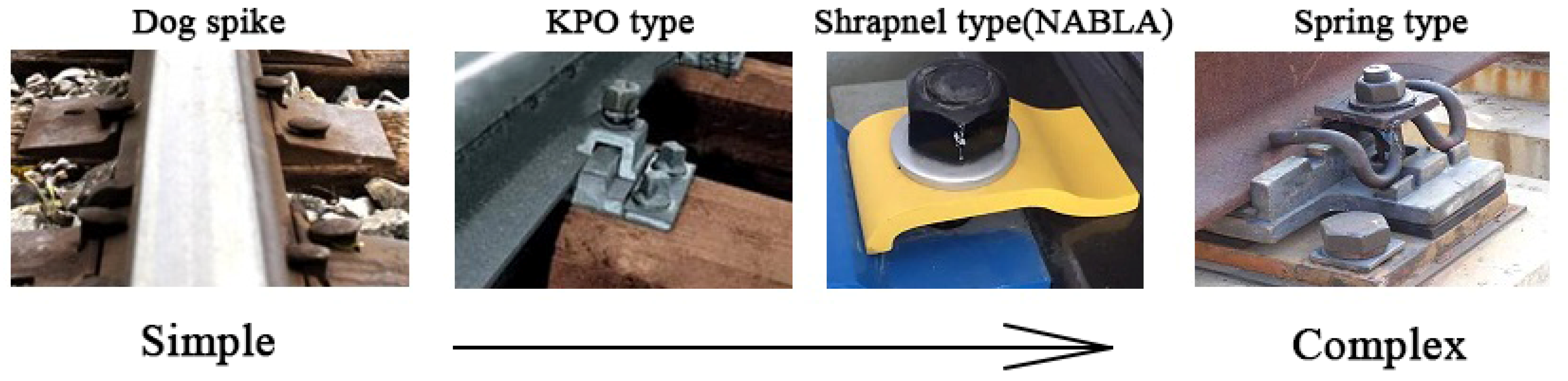
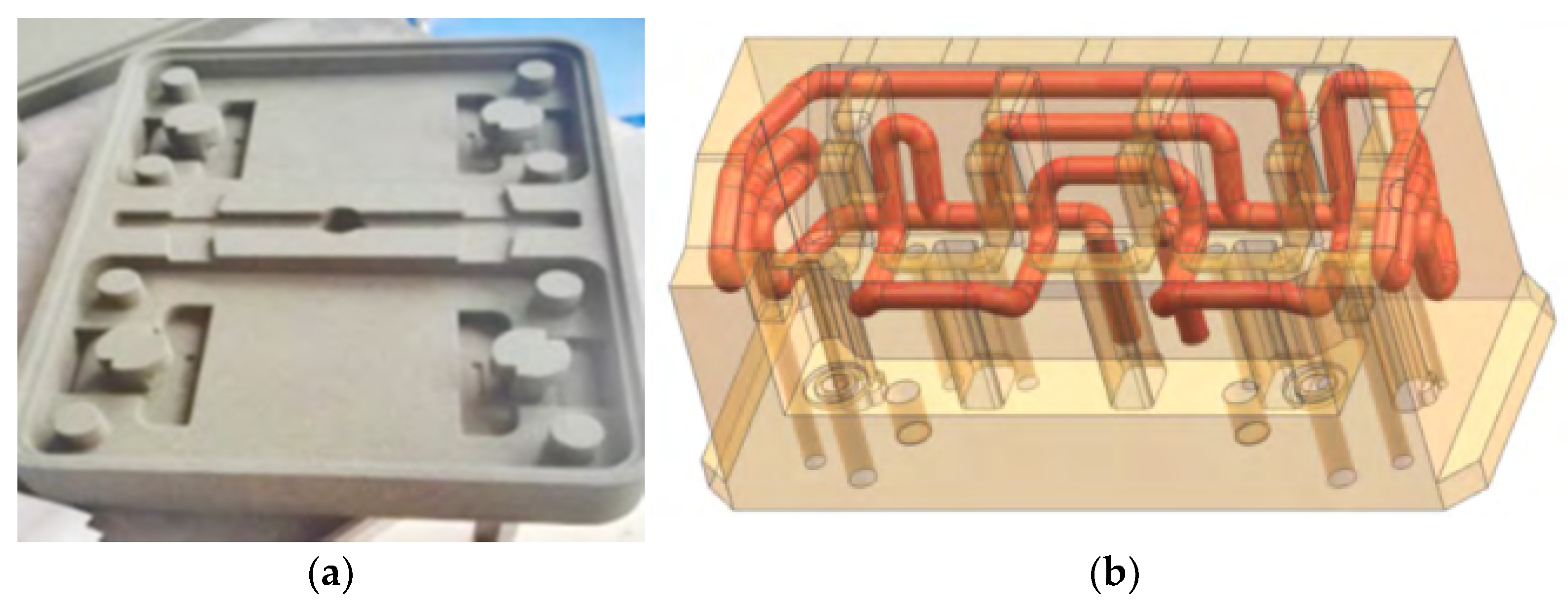
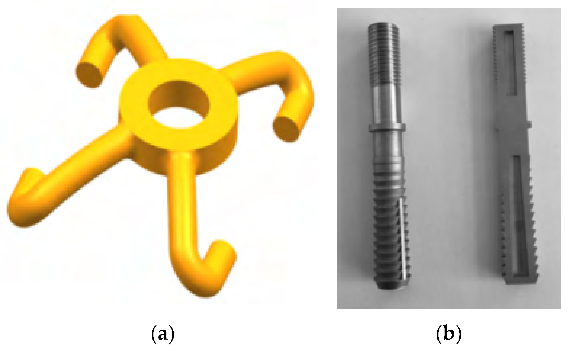
However, it is easy for the fastener systems to fail or be damaged under long-term railway dynamic loads, especially on high-speed and heavy-haul railway lines. In order to design a new type of railway fastener, the CARS in China has adopted 3D printing technology to produce sand-casting moulds for helping fabricate steel fastener plates [81], as present in Figure 7a. Compared with traditional methods, the 3D printing process had shortened the manufacturing time to about 25 days and decreased the cost. Moreover, the 3D printing sand-casting moulds can help the cooling process by the embedded water cooling path, as shown in Figure 7b. The water-cooling path was designed to follow the fastener clip shape, which can make the cooling more effective and reduce the sample deformation. This approach can reduce the moulding time from 150–190 s to 124.5 s. CARS also used the 3D printing technology to optimize the geometry shape of the clip and the crews of the railway fastener system, as shown in Figure 8a,b [81]. The design can decrease material usage, increase elasticity by a special shape, and increase mechanical strength and chemical resistance by combining high-performance materials. Also, reference [82] tested the reinforcing effects of 3D printed bolts on rocks.
Figure 7.
Three-dimensional printed sand-casting moulds: (a) 3D printed moulds for fastener steel plate; (b) schematic smart moulds with embed complex cooling path. Retrieved from [81].
Figure 8.
Optimization of railway fastener clip and screw: (a) schematic clip with shape optimization; (b) 3D printed optimized screws. Retrieved from [81].
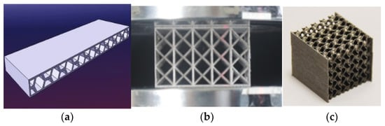
Rail pads in fastener systems provide the most elasticity and can reduce the magnitude of the wheel–rail contact force [83,84]. The dynamic performance of railway fastener systems is affected by the pad material, thickness and geometric shape [85]. Thus, the 3D printing technology can be used to produce elastic pads with enough strength and stiffness for railway fastener systems. There is no report directly related to 3D printed rail pads, but similar research in 3D printed elastic pads has been investigated in aerospace members and civil engineering fields. For example, the cellular honeycomb structures have high specific strength and energy absorption capacity [86]. The stiffness of the honeycomb structure can be designed by a given thickness [87,88,89], which can match different railway line requirements. These honeycomb structures have already been adopted in fabricating aeroplanes to replace conventional metallic components for noise reduction, impact load reduction and thermal control [90,91]. Lattice structures are also a prospecting structure for rail pads. The lattice structures have good vibration properties [92,93,94], high indentation resistance and greater mechanical strength and stiffness when exposed to bending moments and compressive loads [95]. Moreover, by structural design, the lattice structures can gain a negative Poisson’s ratio [96]. Triply periodic minimal surface (TPMS) structures are newly developed porous structures inspired by natural creatures [97,98]. Those TPMS structures have higher specific strength and stiffness compared to common lattice and honeycomb structures [99]. Examples of honeycomb structures, lattice structures and TPMS structures are present in Figure 9. These structures have the potential to be used as elastic sandwich layers in rail pads for their designable stiffness and high specific strength.
Figure 9.
Prospecting structures for rail pads: (a) a honey-comb structure reproduced from [100]; (b) a multi-layer lattice structure, reproduced from [95]; (c) a multi-layer triply periodic minimal surface (TPMS) structure with gyroid surface reproduced from [101].
2.3. Sleepers
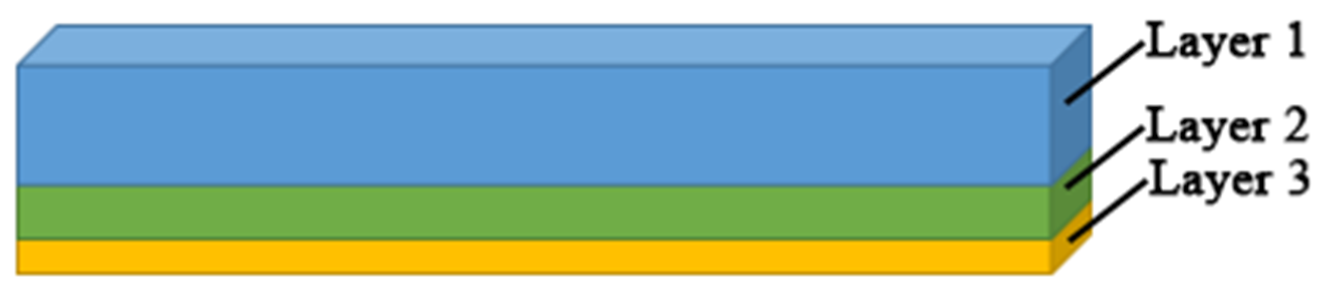
Sleepers support the rail and redistribute the loads to the ballasted layer. The sleepers can be classified into timber, concrete and steel sleepers according to the materials. Concrete sleepers have been widely adopted for their vast resources, good elasticity, long life cycle and good chemical resistance [102]. The optimization of present sleepers is conducted from the material aspects. For example, by adding fibres and rubber particles into composite and concrete sleepers, the mechanical performance of sleepers can be improved. Composite sleepers were newly developed in the 1980s, and the base materials include glass fibre, polyurethane, rubber and resin [103,104]. Because the materials are recyclable and have good elasticity and insulation, the market share of composite sleepers is increasing year by year. The shift2rail project has tried using 3D printing technology to produce a composite bearer with multi-layers [105], as shown in Figure 10. Layer 1 should exceed 150 mm to provide enough stiffness and space for installing fastener systems. layer 3 (soft layer) works as an under-sleeper pad; its depth should exceed 10 mm for 63 mm ballast, 8 mm for 53 mm ballast and 6 mm for ballast less than 53 mm. The depth of layer 2 is determined by the balance of the total depth of bears, layer 1 and layer 3. The required Young’s modulus and density for Layer 1, 2 and 3 decreases as the depth increases.
Figure 10.
Three-dimensional (3D)-printed composite bearers with multi-layers.
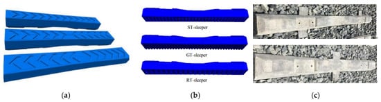
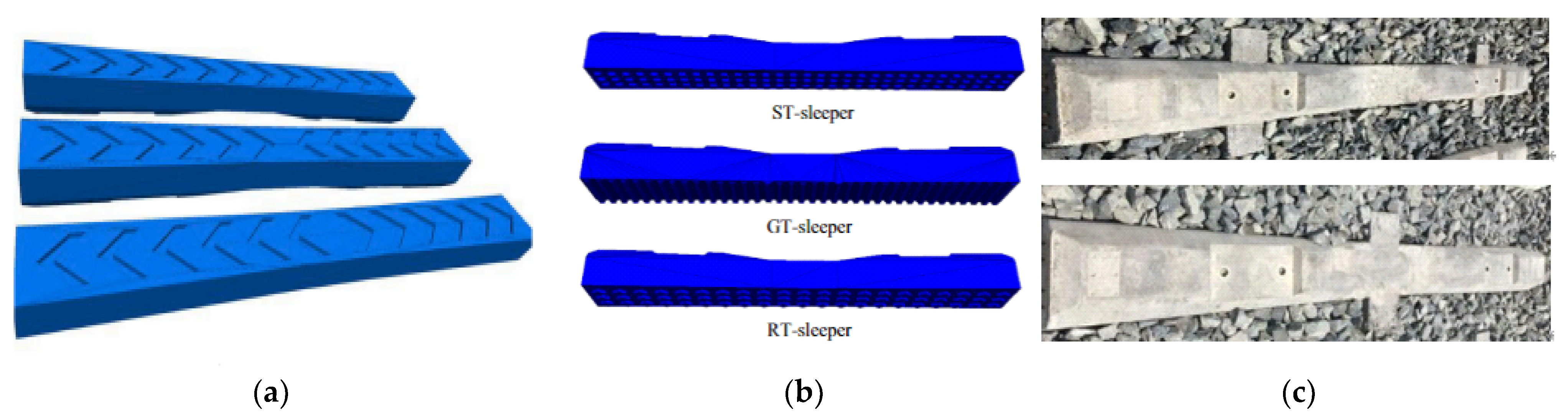
For timber sleepers and concrete sleepers, no research related to additive manufacturing technologies has been conducted. Some researchers have conducted shape optimisation of the sleepers, such as sleepers with arrowhead grooves [106], sleepers with bottom textures [107] and winged sleepers [108,109], as shown in Figure 11. The sleeper can distribute loads more evenly by optimising the geometric shape and providing better lateral and longitudinal resistance [107,108]. It should be noted that producing sleepers with complex shapes using a traditional moulding method is difficult; prototype sleepers with complex shapes for research purposes can be fabricated easily using 3D printing process.
Figure 11.
Shape optimized sleepers; (a) sleepers with arrowhead grooves reproduced from [106]; (b) sleepers with bottom textures reproduced from [107]; (c) winged sleepers reproduced from [108].
2.4. Supporting Layers
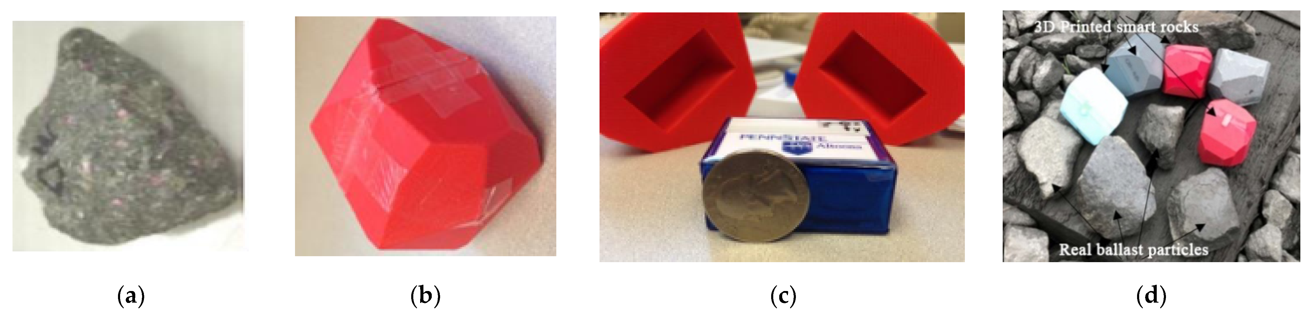
Ballasted beds are the assembly of crushed rock particles with specific particle size distribution, which differs according to the designed railway line conditions. The ballast particles move, rotate and interact with each other under dynamic train loads and then deteriorate. The maintenance of a ballasted track is important for keeping ballasted track with enough stiffness and elasticity. One difficulty of ballasted tracks is to detect the ballasted bed conditions. Because the ballasted bed is composed of small discrete particles with a porosity of 0.2–0.4, it is hard to evaluate the mechanical behaviour of the ballasted layer and access the dynamic reactions of ballast particles. References [110,111,112,113] used 3D printing technology to fabricate several smart ballast rocks to record ballast particle movement (e.g., acceleration and rotation) in field tests. The geometric shapes of smart rocks were obtained by mimicking an actual ballast particle shape, and the removable sensor was installed in the 3D printed rock, as shown in Figure 12. Also, ref. [114] adopted similar SmartRocks to evaluate the ballast condition. Reference [115] 3D printed ballast particles with/without predefined fissure using photosensitive resin material and gypsum powder. Their time-dependent behaviours were compared with limestone ballast particles. The 3D scanning approach was adopted to obtain the geometric shape of real limestone ballast particles. References [116,117] tried using 3D printing technology to fabricate the sample with similar mechanical behaviour to real rocks. The results indicate that 3D printed samples have good mechanical behaviour, but the 3D printing technology still needs to be improved [116,117,118,119].
Figure 12.
Smart ballast particles: (a) real ballast particle; (b) 3D printed smart rock; (c) removable sensor; (d) smart rocks and real ballast particles. Reproduced from [113,120].
A number of railway track slabs, including sleepers on slab systems, embedded sleeper systems and direct systems, have been developed in the past few decades [5]. Most ballast-less track slabs are fabricated from concrete, CA mortar fillings and steel tendons. Many railway companies (e.g., SATEBA in Europe and Stabirail in Belgium) have been developed advanced railway track slabs with optimized geometry for high-speed and heavy-haul railway lines; 3D printing concrete technologies have already been adopted in bridges, civil buildings and art architectures [121,122], which strengthens the railway industry’s desire for 3D printed concrete infrastructures. The British HS2 claimed to launch the ‘Printfra-structure’ project in 2022, which will 3D print concrete slab onsite [123]. The concrete materials will be enhanced with graphene for replacing steel tendons. This approach can decrease carbon emission and concrete usage [123].
2.5. Special Components
Railway track infrastructure includes some special components for addressing particular issues on sites, such as geogrids and geocells for increasing ballast interaction, retaining walls for constraining ballast movement, sound barriers for noise reduction, and sand guard walls for blocking sands. The 3D printing technologies have been utilized in geogrids, geocells and sound barriers.
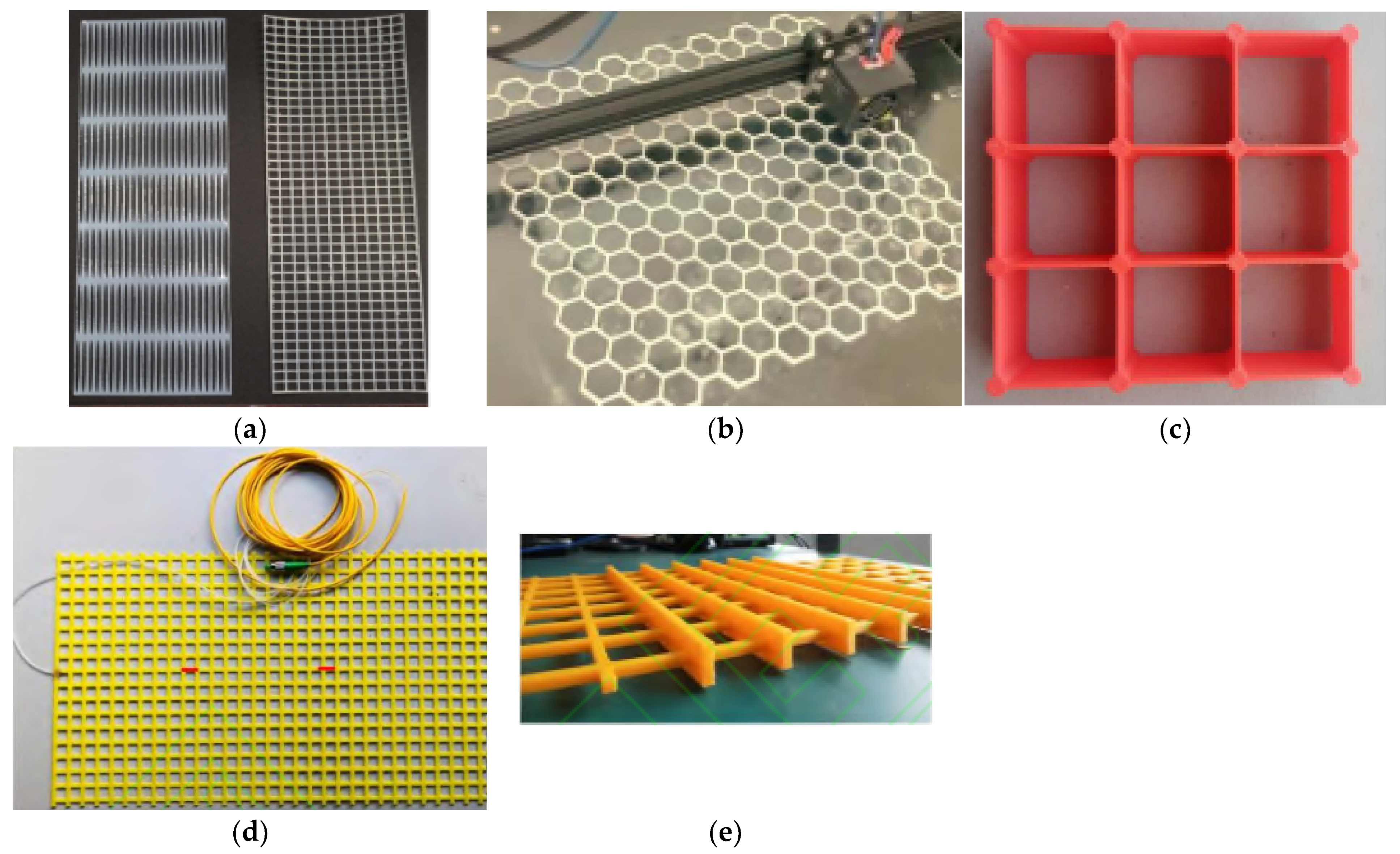
A geogrid and geocells are used to increase the cohesion of granular materials. Reference [124] 3D printed two types of 1:10 mode geogrids, as shown in Figure 13a. The 3D-printed models have lower yielding strain (5% to 6%) than full-scale geogrids (10%), which indicates the printed geogrids need to be enhanced. Reference [125] printed a bio-inspired honeycomb geogrid for soil reinforcement, as shown in Figure 13b. Ref. [126] 3D printed geocells, as shown in Figure 13c, and optimized the integral node shape. Reference [127] printed a smart geogrid, as shown in Figure 13d. The geogrid is equipped with fibre Bragg grating, which enables real-time accurate strain detection. Reference [128] printed a three-dimensional geogrid, as shown in Figure 13e, and tested the shearing performance. These applications can also be used in ballast layers for increasing the ballast biting effects.
Figure 13.
Three-dimensional printed geogrids and geocells: (a) 3D printed 1:10 model geogrids from [124]; (b) a 3D printed bio-inspired honeycomb geogrid from [125]; (c) a 3D printed geocell from [126]; (d) a 3D printed smart geogrid from [127]; (e) a 3D printed three-dimensional geogrid from [128].
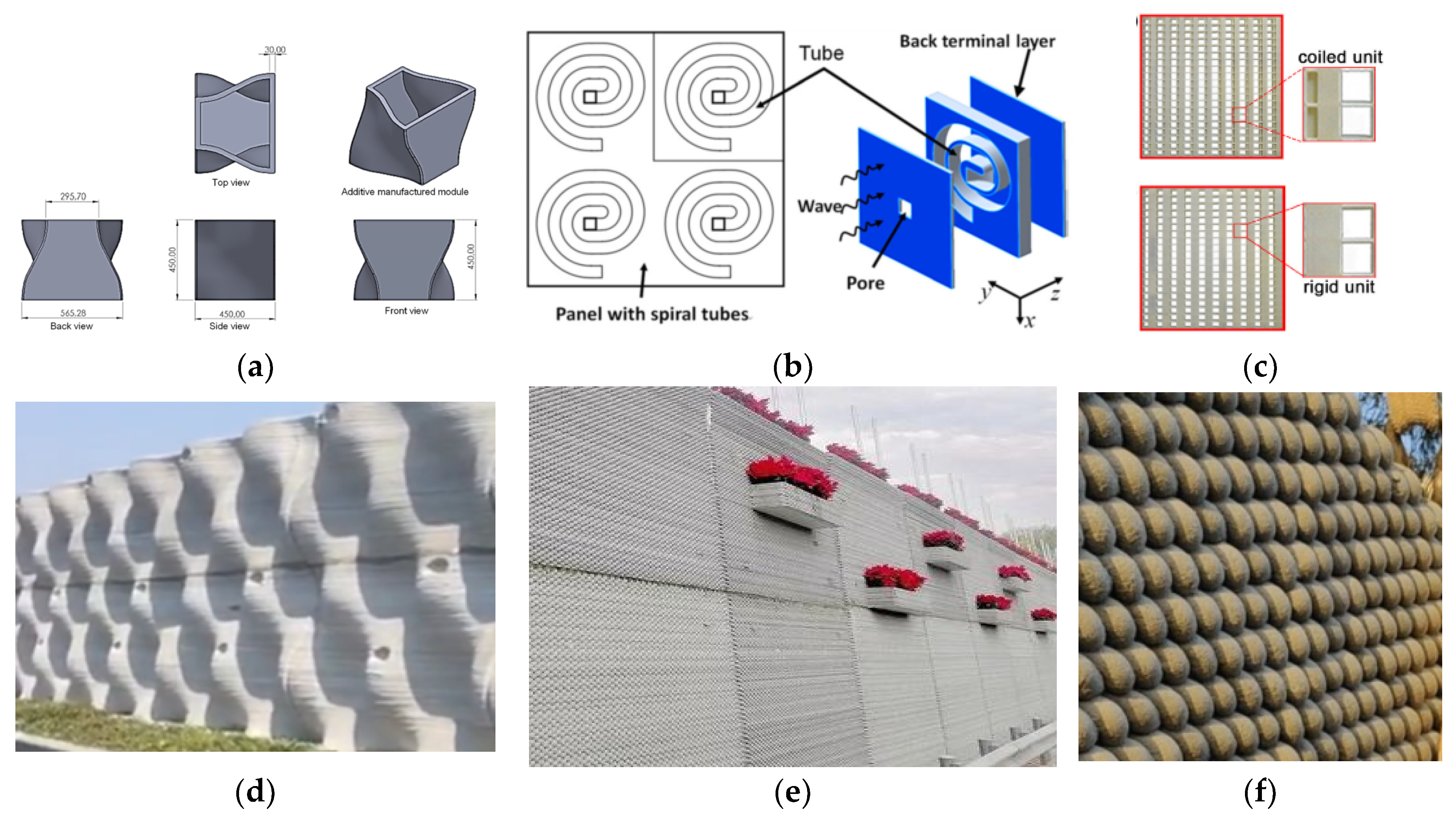
With the development of ultra-high-speed and heavy-haul railway lines, noise has become much more severe and affects the normal life of residents near the railway lines [129]. Sound barriers are a solution for reducing the noise caused by moving railway trains [130,131]. By optimizing the barrier shape, the noise reduction effect can be improved. The 3D printing technology can help produce sound barriers with complex geometric properties. A low-height noise barrier for railway systems was reported in [132]. The size of the unit cell is present in Figure 14a. The unit can be printed in factories and assembled on site. The approach can reduce more than 50% carbon emission [132]. Reference [133] designed a 3D printable ultrathin low-frequency sound absorbing panel, as shown in Figure 14b. Reference [134] designed, 3D printed two types of sound barriers with coiled and rigid unit cells, as shown in Figure 14c, and tested the noise reduction performance. As for 3D printed concrete noise barriers, several acoustic walls, as shown in Figure 14d–f, were built by WINSUN Ltd. in Suzhou, China. These noise barriers can reduce noise by a total of 30 decibels. The 3D printing sound barrier technology is well-developed for adoption in railway noise barriers.
Figure 14.
Three-dimensional printed sound barriers: (a) a low-height noise barrier for railway system (concept by Design Reform Ltd., 2020), from [132]; (b) unit cell of the ultrathin low-frequency sound absorbing panel from [133]; (c) two 3D printed acoustic barrier samples, from [134]; (d–f) 3D printed acoustic walls in Suzhou, China.
3. Challenges
Even though additive manufacturing technologies have many advantages and have been applied in some civil buildings and lightweight structures for aerospace fields, the application of 3D printing in railway engineering is still in the explosion stage. This is due to the limitations as follows.
3.1. Reliability
The materials used for 3D printing can be classified into three main types, including polymer materials (e.g., photosensitive resin, thermoplastic polymer and hydrogels), metallic materials(e.g., Fe-based, Ti-based, Co-based, Cu-based alloys and etc.) and ceramic materials(e.g., cement materials, clay materials and silicate glass materials) [135,136]. Even though those materials can be 3D printed in complex shapes by different additive manufacturing processes, the mechanical properties of many 3D printed samples are usually less than casting samples due to the error in the 3D printing process [137]. Conventional railway track infrastructure is of simple geometric shapes and can be produced easily with well-developed conventional railway construction methods.
Moreover, many additive manufacturing technology processes include heating(melting) and cooling processes, which result in uneven deformation and residual stress inside the 3D printed samples. Other printing processes may also produce defects in 3D printed samples, such as small voids (bubbles) and microcracks. These defects will decrease the strength and life cycle of printed samples. The mechanical performance of 3D printed samples is greatly affected by printing speed, printing orientation, printing temperature, etc. [138]. However, there is no specific standards for 3D printing samples to ensure the 3D printed sample quality. This uncertainty of 3D printed samples hinders the use of 3D printing technology in railway engineering fields. Many 3D printed samples have rough surfaces due to the poorer accuracy than casting mould methods [135]. When additive manufacturing technology is adopted to produce an enhanced layer on the top of rails, grinding and polishing processes are compulsory for making a smooth surface. These processes are time-consuming.
Most importantly, the railway track infrastructure is required to have good fatigue performance under long-term moving train loads [139]. Most 3D printed samples are tested under static and quasi-static loads; the behaviours of 3D printed samples under dynamic loads and long-term loads have not been fully understood yet, which may result in the risk of failure of the railway system under long-term service.
In general, the risk in reliability of 3D printing components in railway engineering is caused by poor raw material properties and 3D printing defects. The development of 3D printable materials, technologies and standards will gradually solve the reliability problems of 3D printing in railway track infrastructures.
3.2. Size and Space Limitation
The size limitations of different 3D printing technologies are different. The maximum size of 3D printed metallic, and polymer samples are usually less than 1 m, which is limited by the size of 3D printing machines. The length of railway sleepers is 2.6 m, and the width of ballast beds and slab tracks are more than 2.6 m [102]. It is not easy to use 3D printing to manufacture all-in-one large-size composite sleepers or track supporting.
3D printing concrete technology allows large size 3D printed constructions, such as 3D printed civil buildings and bridges, but the printing equipment (e.g., robotic arm and removable tracks) needs to be put on-site [140,141]. The land areas of 3D printed houses and bridges are in the order of hundreds of square meters, and the construction site is mostly located in downtown areas on plate ground. Unlike these infrastructures, the length of railway lines is much greater, and much railway infrastructure is located on mountain tunnels, underground tunnels, bridges, and in open suburbs. The field conditions make the preparation and placement of 3D printing machines difficult.
3.3. Cost
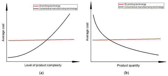
The qualitative comparison of the average cost of fabricating products between 3D printing technology and conventional manufacturing technology is present in Figure 15. The average cost of products fabricated using conventional subtractive manufacturing methods (e.g., CNC) increases when the product complexity increases or when the product quantity decreases. This is because manufacturing products with complex shapes by subtractive technology needs complicated processes (e.g., cutting, drilling and milling). The average cost of 3D printing technologies is not sensitive to product complexity and quantity. Thus, 3D printing technologies show excellent prospects for a small quantity of complex products. However, the geometric shape of railway track infrastructure components is simple, and the demand for railway components for constructing a railway line is massive. This means that using conventional subtractive manufacturing technologies to build railway infrastructures is cheaper than 3D printing technologies, which hinders 3D printing in railway infrastructures.
Figure 15.
Qualitative comparison of costs between 3D printing technology and conventional manufacturing technology. (a) cost of the level of product complexity; (b) cost of the product quantity.
4. Perspectives
Based on the previous study, the highlight findings and the knowledge gap of 3D printing application in railway track infrastructures can be described well in Table 2.
Table 2.
Summary of 3D printing application and research in railway track infrastructure.
Based on the present research of 3D printing in railway engineering and the pros and cons of additive manufacturing technology, the prospects of 3DP technologies in railway engineering are concluded as the following aspects:
- 3D printing technologies can help optimize and construct small components of railway infrastructures, e.g., fastener components (clips, screw spikes and rail pads), geogrids and geocells.
- The rail can be enhanced by additive manufacturing technologies. The approach can help lengthen the life cycle of railway turnout systems by increasing the fatigue behaviour of rails (including stock rails, closure rails, wing rails and guardrails). With the development of new printable metallic and polymer materials, the rails can be fabricated with good mechanical properties using 3D printing technologies.
- 3D printing technologies have the potentials to be used in fabricating composite sleepers (bearers) with multi-layers and producing sleepers with complex shapes.
- 3D printed concrete technologies are well-developed and can be used to construct sound barriers in railway engineering. 3D printing concrete slab track is being prepared in the UK.
- Smart track detection methods can be developed using 3D printing technologies help to detect the track dynamic response in real-time.
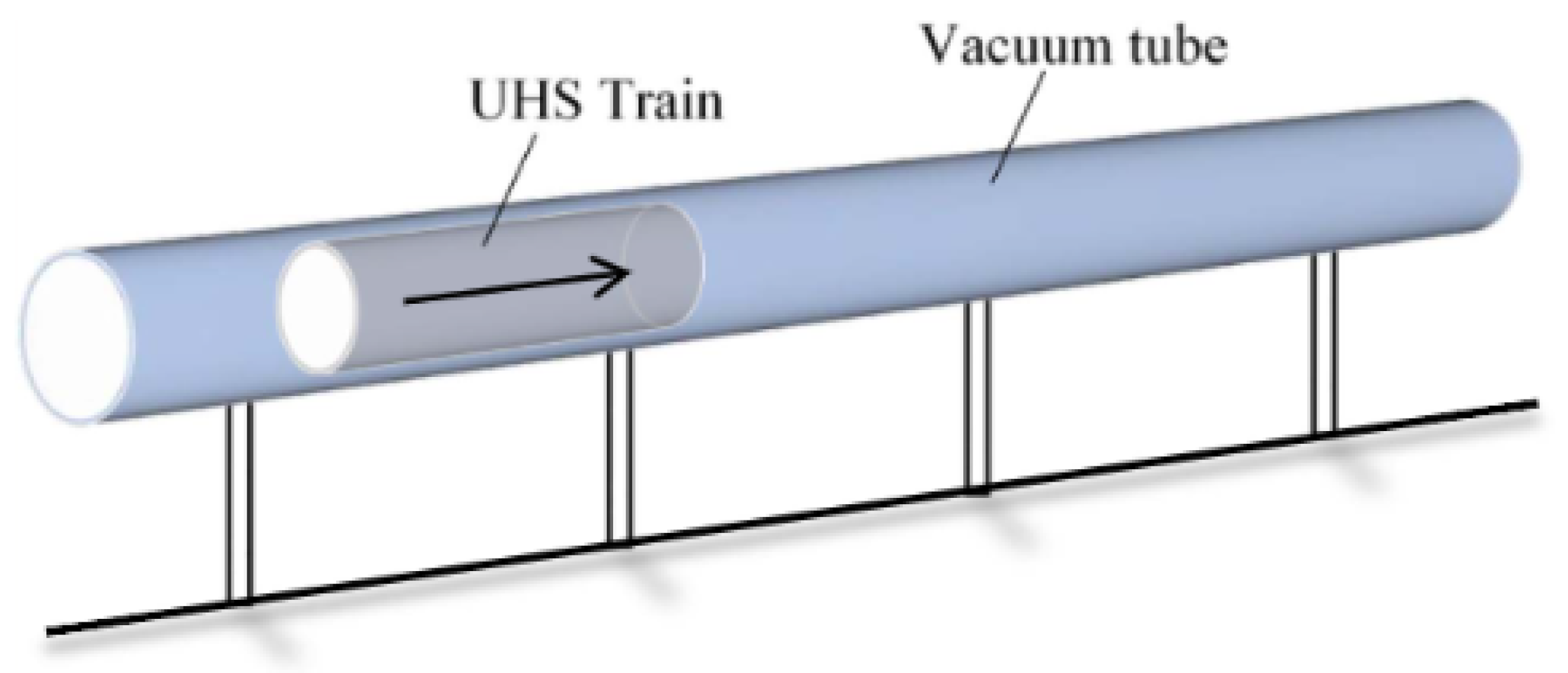
- The 3D printing technologies enable the fabrication of an ultra-high-speed tube track system (also called hyperloop), which allows the train to speed up to 1200 km/h. Figure 16 indicates an initial conceptual design of the prototype hyperloop railway structure. Moreover, all-in-one track supports can be designed with a gradient density in accordance with the stress distribution inside the railway track support. The track stiffness is designable by changing the porosity and structural form of the all-in-one structures. The all-in-one track supports with gradient porosity will have a gradient track stiffness, which can help solve the problem of discontinuous stiffness in the transition areas.Figure 16. A conceptual design of hyperloop track system from [142].
5. Conclusions
This paper presents an overview of 3D printing application and research in railway track infrastructures and the challenges and perspectives of 3D printed railway tracks. The main benefits of additive manufacturing technologies are fabricating complex objects, saving materials, reducing carbon emission, and shortening the product production cycle. The recent research and application of additive manufacturing (3DP) technologies in railway track infrastructures have been reviewed. Presently, the 3DP in railway infrastructures is still in the exploration stage; only the laser melting methods for enhancing rail and wheel surfaces are well developed. This is due to the poor reliability and other limitations of 3D printing technologies for railway engineering. However, 3D printing shows excellent prospects in building all-in-one track infrastructures and designing transition zone supports. In the future, with the development of 3D printing materials, technologies and standards, additive manufacturing will be adopted for building smart railway track infrastructures. This research can promote the research and application of 3D printing in railway engineering.
Author Contributions
Conceptualization, H.F. and S.K.; writing—original draft preparation, H.F.; writing—review and editing, H.F. and S.K.; graphics and visualization, H.F.; project administration, S.K.; funding acquisition, S.K. All authors have read and agreed to the published version of the manuscript.
Funding
The first author has received the PhD scholarship from China Scholarship Council. The research was funded by the European Commission for H2020-MSCA-RISE Project No. 691135 “RISEN: Rail Infrastructure Systems Engineering Network,” which enables a global research network that tackles the grand challenge in railway infrastructure resilience and advanced sensing under extreme conditions [143].
Conflicts of Interest
The authors declare no conflict of interest.
References
- Debrezion, G.; Pels, E.; Rietveld, P. The impact of railway stations on residential and commercial property value: A meta-analysis. J. Real Estate Financ. Econ. 2007, 35, 161–180. [Google Scholar] [CrossRef] [Green Version]
- Kaewunruen, S.; Remennikov, A.M. Dynamic properties of railway track and its components: A state-of-the-art review. New Res. Acoust. 2008, 28, 197–220. [Google Scholar]
- Remennikov, A.M.; Kaewunruen, S. A review of loading conditions for railway track structures due to train and track vertical interaction. Struct. Control Health Monit. 2008, 15, 207–234. [Google Scholar] [CrossRef]
- Kaewunruen, S.; Remennikov, A.M. Current state of practice in railway track vibration isolation: An Australian overview. Aust. J. Civ. Eng. 2016, 14, 63–71. [Google Scholar] [CrossRef]
- Gautier, P.E. Slab track: Review of existing systems and optimization potentials including very high speed. Constr. Build. Mater. 2015, 92, 9–15. [Google Scholar] [CrossRef]
- Tatsuoka, F.; Tateyama, M.; Koda, M.; Koseki, J. Seismic Design, Construction and Performance of Geosynthetic-Reinforced Soil Retaining Walls and Bridge Abutments for Railways in Japan. In Proceedings of the 2013 Geo-Congress, San Diego, CA, USA, 3–7 March 2013. [Google Scholar] [CrossRef]
- Brown, S.F.; Kwan, J.; Thom, N.H. Identifying the key parameters that influence geogrid reinforcement of railway ballast. Geotext. Geomembr. 2007, 25, 326–335. [Google Scholar] [CrossRef]
- Lee, H.P.; Lim, K.M.; Kumar, S. Noise assessment of elevated rapid transit railway lines and acoustic performance comparison of different noise barriers for mitigation of elevated railway tracks noise. Appl. Acoust. 2021, 183, 108340. [Google Scholar] [CrossRef]
- Mehdipour, R.; Baniamerian, Z. A new approach in reducing sand deposition on railway tracks to improve transportation. Aeolian Res. 2019, 41, 100537. [Google Scholar] [CrossRef]
- Zhong, W.; Hu, J.J.; Shen, P.; Wang, C.Y.; Lius, Q.Y. Experimental investigation between rolling contact fatigue and wear of high-speed and heavy-haul railway and selection of rail material. Wear 2011, 271, 2485–2493. [Google Scholar] [CrossRef]
- Tsunashima, H. Condition Monitoring of Railway Tracks from Car-Body Vibration Using a Machine Learning Technique. Appl. Sci. 2019, 9, 2734. [Google Scholar] [CrossRef] [Green Version]
- Seo, J.-W.; Kim, J.C.; Kwon, S.-J.; Jun, H.-K. Effects of Laser Cladding for Repairing and Improving Wear of Rails. Int. J. Precis. Eng. Manuf. 2019, 20, 1207–1217. [Google Scholar] [CrossRef]
- Guo, Y.; Markine, V.; Zhang, X.; Qiang, W.; Jing, G. Image analysis for morphology, rheology and degradation study of railway ballast: A review. Transp. Geotech. 2019, 18, 173–211. [Google Scholar] [CrossRef]
- Li, Y.; Trinh, H.; Haas, N.; Otto, C.; Pankanti, S. Rail Component Detection, Optimization, and Assessment for Automatic Rail Track Inspection. IEEE Trans. Intell. Transp. Syst. 2014, 15, 760–770. [Google Scholar] [CrossRef]
- Ferdous, W.; Manalo, A.; Van Erp, G.; Aravinthan, T.; Ghabraie, K. Evaluation of an Innovative Composite Railway Sleeper for a Narrow-Gauge Track under Static Load. J. Compos. Constr. 2018, 22, 04017050. [Google Scholar] [CrossRef]
- Attaran, M. The rise of 3-D printing: The advantages of additive manufacturing over traditional manufacturing. Bus. Horiz. 2017, 60, 677–688. [Google Scholar] [CrossRef]
- Lipson, H.; Kurman, M. Fabricated: The New World of 3D Printing; John Wiley & Sons: Hoboken, NJ, USA, 2013; Available online: https://www.wiley.com/en-gb/Fabricated%3A+The+New+World+of+3D+Printing-p-9781118416945 (accessed on 6 December 2021).
- ASTM F2792-12a; Standard Terminology for Additive Manufacturing Technologies. ASTM International: Montgomery, PA, USA, 2012. Available online: https://web.mit.edu/2.810/www/files/readings/AdditiveManufacturingTerminology.pdf (accessed on 6 December 2021).
- Bortolini, M.; Calabrese, F.; Galizia, F.G.; Mora, C.; Ventura, V. Industry 4.0 Technologies: A Cross-sector Industry-Based Analysis. In Sustainable Design and Manufacturing, Proceedings of the 8th International Conference on Sustainable Design and Manufacturing (KES-SDM 2021), Split, Croatia, 15–17 September 2021; Springer: Singapore, 2021. [Google Scholar] [CrossRef]
- Gräbe, H.; Mpye, D.; Vandoorne, R.; Broekman, A.; Pienaar, D.; Hawley, C.; van Schalkwyk, H. Advancing the digital railway with 4IR technologies. Civ. Eng. Siviele Ing. 2021, 29, 30–35. [Google Scholar] [CrossRef]
- Shahrubudin, N.; Lee, T.C.; Ramlan, R. An overview on 3D printing technology: Technological, materials, and applications. Procedia Manuf. 2019, 35, 1286–1296. [Google Scholar] [CrossRef]
- Kianian, B. Wohlers Report 2017: 3D Printing and Additive Manufacturing State of the Industry, Annual Worldwide Progress Report; Wohlers Associates, Inc.: Fort Collins, CO, USA, 2017; Available online: https://portal.research.lu.se/en/publications/wohlers-report-2017-3d-printing-and-additive-manufacturing-state- (accessed on 6 December 2021).
- Kwon, Y.M.; Lee, Y.-A.; Kim, S.J. Case study on 3D printing education in fashion design coursework. Fash. Text. 2017, 4, 26. [Google Scholar] [CrossRef] [Green Version]
- Guo, H.-M.; Wang, Q.; Wang, W.-J.; Guo, J.; Liu, Q.-Y.; Zhu, M.-H. Investigation on wear and damage performance of laser cladding Co-based alloy on single wheel or rail material. Wear 2015, 328–329, 329–337. [Google Scholar] [CrossRef]
- Biazon, L.; Ferrer, B.P.; Toro, A.; Cousseau, T. Correlations between rail grease formulation and friction, wear and RCF of a wheel/rail tribological pair. Tribol. Int. 2021, 153, 106566. [Google Scholar] [CrossRef]
- Ringsberg, J.W.; Bjarnehed, H.; Johansson, A.; Josefson, B.L. Rolling contact fatigue of rails—Finite element modelling of residual stresses, strains and crack initiation. Proc. Inst. Mech. Eng. Part F J. Rail Rapid Transit. 2000, 214, 7–19. [Google Scholar] [CrossRef]
- Ringsberg, J.W.; Skyttebol, A.; Josefson, B.L. Investigation of the rolling contact fatigue resistance of laser cladded twin-disc specimens: FE simulation of laser cladding, grinding and a twin-disc test. Int. J. Fatigue 2005, 27, 702–714. [Google Scholar] [CrossRef]
- Zerbst, U.; Lundén, R.; Edel, K.O.; Smith, R.A. Introduction to the damage tolerance behaviour of railway rails—A review. Eng. Fract. Mech. 2009, 76, 2563–2601. [Google Scholar] [CrossRef] [Green Version]
- Wang, X.; Lei, L.; Yu, H. A Review on Microstructural Features and Mechanical Properties of Wheels/Rails Cladded by Laser Cladding. Micromachines 2021, 12, 152. [Google Scholar] [CrossRef] [PubMed]
- Hiensch, M.; Larsson, P.-O.; Nilsson, O.; Levy, D.; Kapoor, A.; Franklin, F.; Nielsen, J.; Ringsberg, J.W.; Josefson, B.L. Two-material rail development: Field test results regarding rolling contact fatigue and squeal noise behaviour. Wear 2005, 258, 964–972. [Google Scholar] [CrossRef]
- Franklin, F.J.; Weeda, G.J.; Kapoor, A.; Hiensch, E.J.M. Rolling contact fatigue and wear behaviour of the infrastar two-material rail. Wear 2005, 258, 1048–1054. [Google Scholar] [CrossRef]
- Hiensch, E.J.M.; Franklin, F.J.; Nielsen, J.C.O.; Ringsberg, J.W.; Weeda, G.J.; Kapoor, A.; Josefson, B.L. Prevention of RCF damage in curved track through development of the INFRA-STAR two-material rail. Fatigue Fract. Eng. Mater. Struct. 2003, 26, 1007–1017. [Google Scholar] [CrossRef]
- Hiensch, M.; Kapoor, A.; Josefson, B.L.; Ringsberg, J.W.; Nielsen, J.; Franklin, F.J. Two-Material Rail Development to Prevent Rolling Contact Fatigue and Reduce Noise Levels in Curved Rail Track. In Proceedings of the 5th World Congress on Railway Research: WCRR 2001, Cologne, Germany, 25–29 November 2001; Available online: http://www.railway-research.org/IMG/pdf/112.pdf (accessed on 6 December 2021).
- Vilar, R. Laser cladding. J. Laser Appl. 1999, 11, 64–79. [Google Scholar] [CrossRef]
- Wang, X.; Deng, D.; Zhang, H. Effects of mass energy and line mass on characteristics of the direct laser fabrication parts. Rapid Prototyp. J. 2018, 24, 270–275. [Google Scholar] [CrossRef]
- Wang, X.; Deng, D.; Hu, Y.; Ning, F.; Wang, H.; Cong, W.; Zhang, H. Overhang structure and accuracy in laser engineered net shaping of Fe-Cr steel. Opt. Laser Technol. 2018, 106, 357–365. [Google Scholar] [CrossRef]
- Thawari, N.; Gullipalli, C.; Chandak, A.; Gupta, T.V.K. Influence of laser cladding parameters on distortion, thermal history and melt pool behaviour in multi-layer deposition of stellite 6: In-situ measurement. J. Alloys Compd. 2021, 860, 157894. [Google Scholar] [CrossRef]
- Shamsaei, N.; Yadollahi, A.; Bian, L.; Thompson, S.M. An overview of Direct Laser Deposition for additive manufacturing; Part II: Mechanical behavior, process parameter optimization and control. Addit. Manuf. 2015, 8, 12–35. [Google Scholar] [CrossRef]
- Zhu, G.; Li, D.; Zhang, A.; Pi, G.; Tang, Y. The influence of laser and powder defocusing characteristics on the surface quality in laser direct metal deposition. Opt. Laser Technol. 2012, 44, 349–356. [Google Scholar] [CrossRef]
- Lai, Q.; Abrahams, R.; Yan, W.; Qiu, C.; Mutton, P.; Paradowska, A.; Soodi, M.; Wu, X. Influences of depositing materials, processing parameters and heating conditions on material characteristics of laser-cladded hypereutectoid rails. J. Mater. Processing Technol. 2019, 263, 1–20. [Google Scholar] [CrossRef]
- Hemmati, I.; Ocelík, V.; De Hosson, J.T.M. The effect of cladding speed on phase constitution and properties of AISI 431 stainless steel laser deposited coatings. Surf. Coat. Technol. 2011, 205, 5235–5239. [Google Scholar] [CrossRef] [Green Version]
- Hemmati, I.; Ocelík, V.; De Hosson, J.T.M. Microstructural characterization of AISI 431 martensitic stainless steel laser-deposited coatings. J. Mater. Sci. 2011, 46, 3405–3414. [Google Scholar] [CrossRef] [Green Version]
- Fu, Z.K.; Ding, H.H.; Wang, W.J.; Liu, Q.Y.; Guo, J.; Zhu, M.H. Investigation on microstructure and wear characteristic of laser cladding Fe-based alloy on wheel/rail materials. Wear 2015, 330–331, 592–599. [Google Scholar] [CrossRef]
- Selcuk, C. Laser metal deposition for powder metallurgy parts. Powder Metall. 2011, 54, 94–99. [Google Scholar] [CrossRef]
- Zhou, S.; Dai, X.; Zheng, H. Microstructure and wear resistance of Fe-based WC coating by multi-track overlapping laser induction hybrid rapid cladding. Opt. Laser Technol. 2012, 44, 190–197. [Google Scholar] [CrossRef]
- Navas, C.; Cadenas, M.; Cuetos, J.M.; de Damborenea, J. Microstructure and sliding wear behaviour of Tribaloy T-800 coatings deposited by laser cladding. Wear 2006, 260, 838–846. [Google Scholar] [CrossRef]
- Clare, A.; Oyelola, O.; Folkes, J.; Farayibi, P. Laser cladding for railway repair and preventative maintenance. J. Laser Appl. 2012, 24, 032004. [Google Scholar] [CrossRef]
- Wang, W.J.; Hu, J.; Guo, J.; Liu, Q.Y.; Zhu, M.H. Effect of laser cladding on wear and damage behaviors of heavy-haul wheel/rail materials. Wear 2014, 311, 130–136. [Google Scholar] [CrossRef]
- Niederhauser, S.; Karlsson, B. Fatigue behaviour of Co–Cr laser cladded steel plates for railway applications. Wear 2005, 258, 1156–1164. [Google Scholar] [CrossRef]
- Meng, L.; Zhao, W.; Hou, K.; Kou, D.; Yuan, Z.; Zhang, X.; Xu, J.; Hu, Q.; Wang, D.; Zeng, X. A comparison of microstructure and mechanical properties of laser cladding and laser-induction hybrid cladding coatings on full-scale rail. Mater. Sci. Eng. A 2019, 748, 1–15. [Google Scholar] [CrossRef]
- Jin, Y.; Ishida, M.; Namura, A. Experimental simulation and prediction of wear of wheel flange and rail gauge corner. Wear 2011, 271, 259–267. [Google Scholar] [CrossRef]
- Lewis, S.R.; Lewis, R.; Fletcher, D.I. Assessment of laser cladding as an option for repairing/enhancing rails. Wear 2015, 330–331, 581–591. [Google Scholar] [CrossRef]
- Wang, X.; Deng, D.; Yi, H.; Xu, H.; Yang, S.; Zhang, H. Influences of pulse laser parameters on properties of AISI316L stainless steel thin-walled part by laser material deposition. Opt. Laser Technol. 2017, 92, 5–14. [Google Scholar] [CrossRef]
- Wang, K.; Chang, B.; Lei, Y.; Fu, H.; Lin, Y. Effect of Cobalt on Microstructure and Wear Resistance of Ni-Based Alloy Coating Fabricated by Laser Cladding. Metals 2017, 7, 551. [Google Scholar] [CrossRef] [Green Version]
- Roy, T.; Paradowska, A.; Abrahams, R.; Law, M.; Mutton, P.; Soodi, M.; Yan, W. Residual stress in laser cladded heavy-haul rails investigated by neutron diffraction. J. Mater. Process. Technol. 2020, 278, 116511. [Google Scholar] [CrossRef]
- Roy, T.; Abrahams, R.; Paradowska, A.; Lai, Q.; Mutton, P.; Soodi, M.; Fasihi, P.; Yan, W. Evaluation of the mechanical properties of laser cladded hypereutectoid steel rails. Wear 2019, 432–433, 202930. [Google Scholar] [CrossRef]
- Meng, L.; Zeng, X.; Hou, K.; Hu, Q.; Wang, D. Effect of laser cladding and laser-induction hybrid cladding coatings on the bending properties and fracture behavior of rails. Surf. Coat. Technol. 2019, 374, 1038–1050. [Google Scholar] [CrossRef]
- Cantini, S.; Cervello, S. The competitive role of wear and RCF: Full scale experimental assessment of artificial and natural defects in railway wheel treads. Wear 2016, 366–367, 325–337. [Google Scholar] [CrossRef]
- Ocelík, V.; de Oliveira, U.; de Boer, M.; de Hosson, J.T.M. Thick Co-based coating on cast iron by side laser cladding: Analysis of processing conditions and coating properties. Surf. Coat. Technol. 2007, 201, 5875–5883. [Google Scholar] [CrossRef] [Green Version]
- De Oliveira, U.; Ocelík, V.; De Hosson, J.T.M. Residual stress analysis in Co-based laser clad layers by laboratory X-rays and synchrotron diffraction techniques. Surf. Coat. Technol. 2006, 201, 533–542. [Google Scholar] [CrossRef] [Green Version]
- Wang, W.J.; Fu, Z.K.; Cao, X.; Guo, J.; Liu, Q.Y.; Zhu, M.H. The role of lanthanum oxide on wear and contact fatigue damage resistance of laser cladding Fe-based alloy coating under oil lubrication condition. Tribol. Int. 2016, 94, 470–478. [Google Scholar] [CrossRef]
- Duarte, V.R.; Rodrigues, T.A.; Schell, N.; Miranda, R.M.; Oliveira, J.P.; Santos, T.G. Hot forging wire and arc additive manufacturing (HF-WAAM). Addit. Manuf. 2020, 35, 101193. [Google Scholar] [CrossRef]
- Donoghue, J.; Antonysamy, A.A.; Martina, F.; Colegrove, P.A.; Williams, S.W.; Prangnell, P.B. The effectiveness of combining rolling deformation with Wire–Arc Additive Manufacture on β-grain refinement and texture modification in Ti–6Al–4V. Mater. Charact. 2016, 114, 103–114. [Google Scholar] [CrossRef]
- Hongxi, L.; Shengwei, J.; Yehua, J.; Xiaowei, Z.; Chuanqi, W. Microstructure and Property of Fe60 Composite Coatings by Rotating Magnetic Field Auxiliary Laser Cladding. Chin. J. Lasers 2013, 40, 0103007. [Google Scholar] [CrossRef]
- Hu, Y.; Wang, L.; Yao, J.; Xia, H.; Li, J.; Liu, R. Effects of electromagnetic compound field on the escape behavior of pores in molten pool during laser cladding. Surf. Coat. Technol. 2020, 383, 125198. [Google Scholar] [CrossRef]
- Lu, P.; Lewis, S.R.; Fretwell-Smith, S.; Engelberg, D.L.; Fletcher, D.I.; Lewis, R. Laser cladding of rail; the effects of depositing material on lower rail grades. Wear 2019, 438–439, 203045. [Google Scholar] [CrossRef]
- Roy, T.; Lai, Q.; Abrahams, R.; Mutton, P.; Paradowska, A.; Soodi, M.; Yan, W. Effect of deposition material and heat treatment on wear and rolling contact fatigue of laser cladded rails. Wear 2018, 412–413, 69–81. [Google Scholar] [CrossRef]
- Zhu, Y.; Yang, Y.; Mu, X.; Wang, W.; Yao, Z.; Yang, H. Study on wear and RCF performance of repaired damage railway wheels: Assessing laser cladding to repair local defects on wheels. Wear 2019, 430–431, 126–136. [Google Scholar] [CrossRef]
- Lewis, S.R.; Fretwell-Smith, S.; Goodwin, P.S.; Smith, L.; Lewis, R.; Aslam, M.; Fletcher, D.I.; Murray, K.; Lambert, R. Improving rail wear and RCF performance using laser cladding. Wear 2016, 366–367, 268–278. [Google Scholar] [CrossRef]
- Lewis, S.R.; Lewis, R.; Goodwin, P.S.; Fretwell-Smith, S.; Fletcher, D.I.; Murray, K.; Jaiswal, J. Full-scale testing of laser clad railway track; Case study—Testing for wear, bend fatigue and insulated block joint lipping integrity. Wear 2017, 376–377, 1930–1937. [Google Scholar] [CrossRef]
- Narayanan, A.; Mostafavi, M.; Pirling, T.; Kabra, S.; Lewis, R.; Pavier, M.J.; Peel, M.J. Residual stress in laser cladded rail. Tribol. Int. 2019, 140, 105844. [Google Scholar] [CrossRef]
- Aladesanmi, V.I.; Fatoba, O.S.; Akinlabi, E.T. Laser cladded Ti+TiB2 on Steel Rail Microstructural Effect. Procedia Manuf. 2019, 33, 709–716. [Google Scholar] [CrossRef]
- Chen, S.-E.; Shanmugam, N.S.; Boyajian, D.; Chavan, V.S.; Weber, E.; Baarsons, K. Prototyping rail track for micro-people movers using additive manufacturing: Failure topology characterization. Constr. Build. Mater. 2021, 281, 122623. [Google Scholar] [CrossRef]
- Gao, X.; Feng, Q.; Wang, A.; Sheng, X.; Cheng, G. Testing research on frequency-dependent characteristics of dynamic stiffness and damping for high-speed railway fastener. Eng. Fail. Anal. 2021, 129, 105689. [Google Scholar] [CrossRef]
- Li, L.; Thompson, D.; Xie, Y.; Zhu, Q.; Luo, Y.; Lei, Z. Influence of rail fastener stiffness on railway vehicle interior noise. Appl. Acoust. 2019, 145, 69–81. [Google Scholar] [CrossRef] [Green Version]
- Thompson, D.J.; Verheij, J.W. The dynamic behaviour of rail fasteners at high frequencies. Appl. Acoust. 1997, 52, 1–17. [Google Scholar] [CrossRef] [Green Version]
- Mohammadzadeh, S.; Ahadi, S.; Keshavarzian, H. Assessment of fracture reliability analysis of crack growth in spring clip type Vossloh SKL14. Proc. Inst. Mech. Eng. Part O J. Risk Reliab. 2014, 228, 460–468. [Google Scholar] [CrossRef]
- Jaroslav, S.; Lubos, P.; Vladimir, T.; Herbert, S. Assessment of Dynamic Parameters of Rail Fastening. Commun. Sci. Lett. Univ. Zilina 2016, 18, 65–70. [Google Scholar]
- Ma, A.; Lv, Z.; Chen, X.; Li, L.; Qiu, Y.; Zheng, S.; Chai, X. Pandrol track fastener defect detection based on local convolutional neural networks. Proc. Inst. Mech. Eng. Part I J. Syst. Control Eng. 2020, 235, 1906–1915. [Google Scholar] [CrossRef]
- Gao, X.; Wang, A.; Liu, L.; He, Y.; Ju, L. Analysis of failure mechanism of W1-type fastening clip in high speed railway and structure study of damping composite. Eng. Fail. Anal. 2020, 118, 104848. [Google Scholar] [CrossRef]
- Zheng, Z.; Hongchao, X.; Liang, Y. Exploring on Application of 3D Printing Technology in Field of Track Structure. Railw. Eng. 2017, 1, 44–47. [Google Scholar] [CrossRef]
- Feng, X.; Xue, F.; Wang, T.; Wang, L.; Zhao, T.; Liu, X. Reinforcing effects of 3D printed bolts on joint-separated standard soft rock specimens. Compos. Part B Eng. 2020, 193, 108024. [Google Scholar] [CrossRef]
- Remennikov, A.; Kaewunruen, S. Simulating Shock Loads in Railway Track Environments: Experimental Studies. 2007. Available online: https://ro.uow.edu.au/engpapers/375/ (accessed on 6 December 2021).
- Kaewunruen, S.; Remennikov, A. An Experimental Evaluation of the Attenuation Effect of Rail Pad on Flexural Behaviour of Railway Concrete Sleeper under Severe Impact Loads. 2008. Available online: https://ro.uow.edu.au/engpapers/469/ (accessed on 6 December 2021).
- Cox, S.J.; Grassie, S.L. The dynamic response of railway track to discrete irregularities. Veh. Syst. Dyn. 1988, 17, 86–89. [Google Scholar] [CrossRef]
- Grima, J.N.; Cauchi, R.; Gatt, R.; Attard, D. Honeycomb composites with auxetic out-of-plane characteristics. Compos. Struct. 2013, 106, 150–159. [Google Scholar] [CrossRef]
- Qiao, P.; Yang, M. Impact analysis of fiber reinforced polymer honeycomb composite sandwich beams. Compos. Part B Eng. 2007, 38, 739–750. [Google Scholar] [CrossRef]
- Xu, C.; Wu, M.-Z.; Hamdaoui, M. Mixed integer multi-objective optimization of composite structures with frequency-dependent interleaved viscoelastic damping layers. Comput. Struct. 2016, 172, 81–92. [Google Scholar] [CrossRef] [Green Version]
- Li, Z.; Crocker, M.J. Effects of thickness and delamination on the damping in honeycomb–foam sandwich beams. J. Sound Vib. 2006, 294, 473–485. [Google Scholar] [CrossRef]
- Seepersad, C.C.; Dempsey, B.M.; Allen, J.K.; Mistree, F.; McDowell, D.L. Design of Multifunctional Honeycomb Materials. AIAA J. 2004, 42, 1025–1033. [Google Scholar] [CrossRef]
- Dempsey, B.M.; Eisele, S.; McDowell, D.L. Heat sink applications of extruded metal honeycombs. Int. J. Heat Mass Transf. 2005, 48, 527–535. [Google Scholar] [CrossRef]
- Chen, C.P.; Lakes, R.S. Dynamic wave dispersion and loss properties of conventional and negative Poisson’s ratio polymeric cellular materials. Cell Polym. 1989, 8, 343–359. Available online: http://silver.neep.wisc.edu/~lakes/PoissonCutOffFr.pdf (accessed on 6 December 2021).
- Wang, J.; Evans, A.G.; Dharmasena, K.; Wadley, H.N.G. On the performance of truss panels with Kagomé cores. Int. J. Solids Struct. 2003, 40, 6981–6988. [Google Scholar] [CrossRef]
- Deshpande, V.S.; Fleck, N.A.; Ashby, M.F. Effective properties of the octet-truss lattice material. J. Mech. Phys. Solids 2001, 49, 1747–1769. [Google Scholar] [CrossRef] [Green Version]
- Lei, H.; Li, C.; Meng, J.; Zhou, H.; Liu, Y.; Zhang, X.; Wang, P.; Fang, D. Evaluation of compressive properties of SLM-fabricated multi-layer lattice structures by experimental test and μ-CT-based finite element analysis. Mater. Des. 2019, 169, 107685. [Google Scholar] [CrossRef]
- Clarke, J.F.; Duckett, R.A.; Hine, P.J.; Hutchinson, I.J.; Ward, I.M. Negative Poisson’s ratios in angle-ply laminates: Theory and experiment. Composites 1994, 25, 863–868. [Google Scholar] [CrossRef]
- Saranathan, V.; Osuji, C.O.; Mochrie, S.G.; Noh, H.; Narayanan, S.; Sandy, A.; Dufresne, E.R.; Prum, R.O. Structure, function, and self-assembly of single network gyroid (I4132) photonic crystals in butterfly wing scales. Proc. Natl. Acad. Sci. USA 2010, 107, 11676–11681. [Google Scholar] [CrossRef] [Green Version]
- Al-Ketan, O.; Soliman, A.; AlQubaisi, A.M.; Abu Al-Rub, R.K. Nature-Inspired Lightweight Cellular Co-Continuous Composites with Architected Periodic Gyroidal Structures. Adv. Eng. Mater. 2018, 20, 1700549. [Google Scholar] [CrossRef]
- Lee, D.-W.; Khan, K.A.; Abu Al-Rub, R.K. Stiffness and yield strength of architectured foams based on the Schwarz Primitive triply periodic minimal surface. Int. J. Plast. 2017, 95, 1–20. [Google Scholar] [CrossRef]
- Pirouzfar, S.; Zeinedini, A. Effect of geometrical parameters on the flexural properties of sandwich structures with 3D-printed honeycomb core and E-glass/epoxy Face-sheets. Structures 2021, 33, 2724–2738. [Google Scholar] [CrossRef]
- Zhang, L.; Feih, S.; Daynes, S.; Chang, S.; Wang, M.Y.; Wei, J.; Lu, W.F. Energy absorption characteristics of metallic triply periodic minimal surface sheet structures under compressive loading. Addit. Manuf. 2018, 23, 505–515. [Google Scholar] [CrossRef]
- Jing, G.; Siahkouhi, M.; Riley Edwards, J.; Dersch, M.S.; Hoult, N.A. Smart railway sleepers—A review of recent developments, challenges, and future prospects. Constr. Build. Mater. 2021, 271, 121533. [Google Scholar] [CrossRef]
- Kaewunruen, S. Acoustic and Dynamic Characteristics of a Complex Urban Turnout Using Fibre-Reinforced Foamed Urethane (FFU) Bearers. In Noise and Vibration Mitigation for Rail Transportation Systems, Proceedings of the 11th International Workshop on Railway Noise, Uddevalla, Sweden, 9–13 September 2013; Springer: Berlin/Heidelberg, Germany, 2015; pp. 377–384. [Google Scholar]
- Kaewunruen, S.; You, R.; Ishida, M. Composites for Timber-Replacement Bearers in Railway Switches and Crossings. Infrastructures 2017, 2, 13. [Google Scholar] [CrossRef] [Green Version]
- D4.1 Novel Materials and Additive Manufacturing Processes, Including Opportunities to Improve Logistics and Installation. Available online: http://www.s-code.info/media/1095/d41-report-novel-materials-and-additive-manufacturing-processes-including-opportunities-to-improve-logistics-and-installation.pdf (accessed on 6 December 2021).
- Jing, G.; Jia, W.; Wang, X.; Markine, V.; Nålsund, R.; Guo, Y. Experimental and numerical study on lateral resistance of frictional sleeper with arrowhead groove. Transp. Geotech. 2021, 30, 100638. [Google Scholar] [CrossRef]
- Guo, Y.; Fu, H.; Qian, Y.; Markine, V.; Jing, G. Effect of sleeper bottom texture on lateral resistance with discrete element modelling. Constr. Build. Mater. 2020, 250, 118770. [Google Scholar] [CrossRef]
- Jing, G.Q.; Aela, P.; Fu, H.; Yin, H. Numerical and experimental analysis of single tie push tests on different shapes of concrete sleepers in ballasted tracks. Proc. Inst. Mech. Eng. Part F J. Rail Rapid Transit. 2018, 233, 666–677. [Google Scholar] [CrossRef]
- Takahashi, R.; Hayano, K.; Nakamura, T.; Momoya, Y. Integrated risk of rail buckling in ballasted tracks at transition zones and its countermeasures. Soils Found. 2019, 59, 517–531. [Google Scholar] [CrossRef]
- Liu, S.; Huang, H.; Qiu, T. Laboratory Development and Testing of “SmartRock” for Railroad Ballast Using Discrete Element Modeling. In Proceedings of the 2015 Joint Rail Conference, San Jose, CA, USA, 23–26 March 2015. [Google Scholar] [CrossRef]
- Liu, S.; Huang, H.; Qiu, T.; Gao, Y. Study on Ballast Particle Movement at Different Locations Beneath Crosstie Using “SmartRock”. In Proceedings of the 2016 Joint Rail Conference, Columbia, SC, USA, 12–15 April 2016. [Google Scholar] [CrossRef]
- Liu, S.; Huang, H.; Qiu, T.; Kwon, J. Comparative Evaluation of Particle Movement in a Ballast Track Structure Stabilized with Biaxial and Multiaxial Geogrids. Transp. Res. Rec. 2017, 2607, 15–23. [Google Scholar] [CrossRef]
- Liu, S.; Qiu, T.; Qian, Y.; Huang, H.; Tutumluer, E.; Shen, S. Simulations of large-scale triaxial shear tests on ballast aggregates using sensing mechanism and real-time (SMART) computing. Comput. Geotech. 2019, 110, 184–198. [Google Scholar] [CrossRef]
- Zeng, K.; Qiu, T.; Bian, X.; Xiao, M.; Huang, H. Identification of ballast condition using SmartRock and pattern recognition. Constr. Build. Mater. 2019, 221, 50–59. [Google Scholar] [CrossRef]
- Xu, M.; Jin, D.; Zhou, W. An experimental study on the time-dependent behavior of crushable granular materials using 3D-printed particles. Acta Geotech. 2021. [Google Scholar] [CrossRef]
- Fereshtenejad, S.; Song, J.-J. Fundamental Study on Applicability of Powder-Based 3D Printer for Physical Modeling in Rock Mechanics. Rock Mech. Rock Eng. 2016, 49, 2065–2074. [Google Scholar] [CrossRef]
- Jiang, Q.; Feng, X.; Song, L.; Gong, Y.; Zheng, H.; Cui, J. Modeling rock specimens through 3D printing: Tentative experiments and prospects. Acta Mech. Sin. 2016, 32, 101–111. [Google Scholar] [CrossRef]
- Head, D.; Vanorio, T. Effects of changes in rock microstructures on permeability: 3-D printing investigation. Geophys. Res. Lett. 2016, 43, 7494–7502. [Google Scholar] [CrossRef] [Green Version]
- Ishutov, S.; Hasiuk, F.; Harding, C.; Gray, J. 3D printing sandstone porosity models. Interpretation 2015, 3, SX49–SX61. [Google Scholar] [CrossRef]
- Liu, S.; Huang, H.; Qiu, T.; Kerchof, B. Characterization of Ballast Particle Movement at Mud Spot. J. Mater. Civ. Eng. 2019, 31, 04018339. [Google Scholar] [CrossRef]
- Al Rashid, A.; Khan, S.A.; Al-Ghamdi, G.S.; Koç, M. Additive manufacturing: Technology, applications, markets, and opportunities for the built environment. Autom. Constr. 2020, 118, 103268. [Google Scholar] [CrossRef]
- Bhardwaj, A.; Jones, S.Z.; Kalantar, N.; Pei, Z.; Vickers, J.; Wangler, T.; Zavattieri, P.; Zou, N. Additive Manufacturing Processes for Infrastructure Construction: A Review. J. Manuf. Sci. Eng. 2019, 141, 091010. [Google Scholar] [CrossRef]
- HS2. HS2 Harnessing the Power of Pioneering 3D Concrete Printing to Help Cut Carbon on Project by Up to 50%. Available online: https://mediacentre.hs2.org.uk/news/3d-concrete-printing-and-graphene-combined-on-hs2-set-to-cut-carbon-content-by-up-to-50-percent (accessed on 6 December 2021).
- Stathas, D.; Wang, J.P.; Ling, H.I. Model geogrids and 3D printing. Geotext. Geomembr. 2017, 45, 688–696. [Google Scholar] [CrossRef]
- Arab, M.G.; Omar, M.; Alotaibi, E.; Mostafa, O.; Naeem, M.; Badr, O. Bio-Inspired 3D-Printed Honeycomb for Soil Reinforcement. In Proceedings of the Geo-Congress 2020, Minneapolis, MN, USA, 25–28 February 2020; American Society of Civil Engineers: Reston, VA, USA, 2020; pp. 262–271. [Google Scholar] [CrossRef]
- Amurane, I.; Zhang, M.; Li, T.; Jiang, H. Optimization of 3D printed geocells based on numerical simulation and experimental investigation. IOP Conf. Ser. Earth Environ. Sci. 2019, 233, 032043. [Google Scholar] [CrossRef]
- Jie, Y.; Mengxi, Z.; Chengchun, Q. Model Test of Reinforced by Geogrid Subgrade Underlying Sinkholes Based on FBG-3D Printing. J. Shanghai Univ. 2021, 1–9. Available online: https://kns.cnki.net/kcms/detail/31.1718.N.20210510.1515.004.html (accessed on 6 December 2021).
- Feiyu, L.; Wenjing, W.; Fu, H.; Jun, W.; Chaoliang, W.; Mingfeng, L. Research on Shear Behavior of 3D Printed Three-dimensional Geogrid-sand Interface. China J. Highw. Transp. 2021, 1–10. Available online: https://kns.cnki.net/kcms/detail/61.1313.U.20210129.1503.008.html (accessed on 6 December 2021).
- Zhang, X.; Liu, R.; Cao, Z.; Wang, X.; Li, X. Acoustic performance of a semi-closed noise barrier installed on a high-speed railway bridge: Measurement and analysis considering actual service conditions. Measurement 2019, 138, 386–399. [Google Scholar] [CrossRef]
- Patience, C.; Jones, E. High Speed Architecture: HS2’s Colne Valley Viaduct. Struct. Eng. Int. 2021, 31, 550–557. [Google Scholar] [CrossRef]
- Li, X.; Hu, X.; Zheng, J. Statistical energy method for noise reduction performance of the vertical noise barrier alongside railway bridges. Appl. Acoust. 2020, 170, 107503. [Google Scholar] [CrossRef]
- Abdulkareem, M.; Havukainen, J.; Nuortila-Jokinen, J.; Horttanainen, M. Life cycle assessment of a low-height noise barrier for railway traffic noise. J. Clean. Prod. 2021, 323, 129169. [Google Scholar] [CrossRef]
- Cai, X.; Guo, Q.; Hu, G.; Yang, J. Ultrathin low-frequency sound absorbing panels based on coplanar spiral tubes or coplanar Helmholtz resonators. Appl. Phys. Lett. 2014, 105, 121901. [Google Scholar] [CrossRef] [Green Version]
- Zhang, H.-l.; Zhu, Y.-F.; Liang, B.; Yang, J.; Yang, J.; Cheng, J.-C. Omnidirectional ventilated acoustic barrier. Appl. Phys. Lett. 2017, 111, 203502. [Google Scholar] [CrossRef] [Green Version]
- Quan, Z.; Wu, A.; Keefe, M.; Qin, X.; Yu, J.; Suhr, J.; Byun, J.-H.; Kim, B.-S.; Chou, T.-W. Additive manufacturing of multi-directional preforms for composites: Opportunities and challenges. Mater. Today 2015, 18, 503–512. [Google Scholar] [CrossRef]
- Parandoush, P.; Lin, D. A review on additive manufacturing of polymer-fiber composites. Compos. Struct. 2017, 182, 36–53. [Google Scholar] [CrossRef]
- Yu, T.; Zhao, Y.; Bi, X.; Song, B.; Chen, Y. Mechanical properties of porous structure 3D printed with Vero White photosensitive resin. Rapid Prototyp. J. 2019, 26, 539–548. [Google Scholar] [CrossRef]
- Farzadi, A.; Solati-Hashjin, M.; Asadi-Eydivand, M.; Abu Osman, N.A. Effect of layer thickness and printing orientation on mechanical properties and dimensional accuracy of 3D printed porous samples for bone tissue engineering. PLoS ONE 2014, 9, e108252. [Google Scholar] [CrossRef] [PubMed]
- Aikawa, A. Dynamic characterisation of a ballast layer subject to traffic impact loads using three-dimensional sensing stones and a special sensing sleeper. Constr. Build. Mater. 2015, 92, 23–30. [Google Scholar] [CrossRef]
- Bueno, F.; Alejandro, S. Reusable 3D Printed Concrete Slab: An Approach towards the Optimisation of the Usage of Concrete in the Built Environment; Delft University of Technology: Delft, The Netherlands, 2019; Available online: https://repository.tudelft.nl/islandora/object/uuid%3A18204804-985b-4d61-b883-84c934349533 (accessed on 6 December 2021).
- Jipa, A.; Dillenburger, B. 3D Printed Formwork for Concrete: State-of-the-Art, Opportunities, Challenges, and Applications. 3D Print. Addit. Manuf. 2021. [Google Scholar] [CrossRef]
- Alexander, N.A.; Kashani, M.M. Exploring bridge dynamics for ultra-high-speed, hyperloop, trains. Structures 2018, 14, 69–74. [Google Scholar] [CrossRef] [Green Version]
- Kaewunruen, S.; Sussman, J.M.; Matsumoto, A. Grand Challenges in Transportation and Transit Systems. Front. Built Environ. 2016, 2, 4. [Google Scholar] [CrossRef] [Green Version]


Publisher’s Note: MDPI stays neutral with regard to jurisdictional claims in published maps and institutional affiliations. |
© 2021 by the authors. Licensee MDPI, Basel, Switzerland. This article is an open access article distributed under the terms and conditions of the Creative Commons Attribution (CC BY) license (https://creativecommons.org/licenses/by/4.0/).