


Abstract
Transient extrusion defects are a fundamental process control challenge in fused granular fabrication (FGF), arising from the finite melt pressurization time of screw-driven extruders at each start–stop event. This study presents an integrated experimental and analytical framework for the characterization and open-loop feedforward compensation of these transient dynamics, demonstrated on two composite thermoplastic feedstocks: a recycled random polypropylene (RPP1) and a 20 wt% wood-fiber-reinforced polypropylene composite (WFPP). Unlike prior filament- or single-material feedforward strategies, this framework derives and statistically validates material-specific compensation parameters across two rheologically distinct feedstocks. Single-layer road experiments were conducted on a custom instrumented FGF platform across a 23−1 half-fraction factorial design varying melt temperature, print acceleration, and nozzle diameter, with screw speed stepped among 20, 40, and 80 RPM to excite transient states; deposited road geometry was digitized and spatially registered to the synchronized process signals. Main-effects regression confirmed that nozzle diameter is the dominant predictor of mean road width, while screw velocity exerts a significant negative effect attributable to speed-dependent backflow. Prediction-error minimization on the pooled multi-experiment dataset yielded a parsimonious first-order transfer function, G(s) = 0.990/(1 + 1.909s), whose time constant is physically attributed to melt compressibility in the barrel volume upstream of the nozzle restriction. This model was embedded in a G-code post-processor implementing two sequential corrections: a material-specific steady-state slip gain and a discrete linear-advance term parameterized by the identified time constant. For RPP1 at the nominal gain, the print latency interquartile range decreased from 5–20 mm to 2–8 mm without degrading steady-state dimensional accuracy; the combination of nominal gain with active retraction further reduced latency to near-zero. Analysis of covariance (ANCOVA) confirmed that optimal feedforward gains are statistically material-dependent across all three quality metrics (p < 0.05), providing statistical justification for material-specific compensator parameterization. The results establish a practical, hardware-agnostic route to reduce transient deposition defects in pellet-based additive manufacturing, extensible to additional feedstocks.
1. Introduction
Fused granular fabrication (FGF), also referred to in the literature as pellet-based additive manufacturing (PAM) or, at the industrial scale, Big Area Additive Manufacturing (BAAM), has emerged as one of the most practically significant advances in polymer material extrusion over the past decade [1,2,3]. Unlike fused filament fabrication (FFF), in which a pre-formed filament acts as a positive-displacement piston to drive melt flow, FGF feeds raw polymer pellets directly into a single-screw extrusion unit mounted on a multi-axis motion platform [1,4]. This architectural distinction confers considerable practical advantages: pellet feedstocks are available at a fraction of the cost of equivalent filament grades, the range of processable materials is vastly broader, and volumetric deposition rates achievable with screw-driven systems can exceed those of filament-fed counterparts by two or more orders of magnitude [5,6]. These attributes have positioned FGF as an enabling technology for large-format structural applications—spanning tooling, molds, architectural components, and near-net-shape preforms—that remain inaccessible to conventional filament-based processes [4,6].
A further dimension of growing practical relevance is the integration of post-consumer recycled (PCR) thermoplastics and fiber-reinforced thermoplastic composites as FGF feedstocks. Polypropylene (PP) represents one of the highest-volume commodity plastics in global production, yet its recycling rate remains disproportionately low relative to its end-of-life volume [7,8]. Deploying PCR-PP directly as a pellet feedstock in FGF circumvents the energy-intensive and quality-degrading intermediate step of filament extrusion, offering a more viable pathway to circularity in polymer manufacturing [8,9,10]. Wood-fiber-reinforced polypropylene composites (WFPP) combine lignocellulosic filler recovered from industrial waste streams with a polypropylene matrix that is amenable to single-screw extrusion [11], a direction of growing interest reflected in recent work on flax-fiber-reinforced PP structures processed via FGF [12]. However, the rheological complexity introduced by recycling-induced molecular weight degradation in PCR-PP, and by the pseudoplastic, viscoelastic, and wall-slip behavior characteristic of wood–polymer composites [11,13], compounds the process control challenge inherent to screw-driven deposition systems.
A fundamental and insufficiently characterized challenge common to all FGF feedstocks is the class of transient extrusion defects that manifest at the onset and termination of each deposited road—phenomena commonly referred to in practice as lag and drool respectively. Lag describes the finite delay between the commanded onset of screw rotation and the establishment of steady-state melt flow at the nozzle exit, during which the deposited road width is completely absent or measurably below its target value. Drool describes the complementary phenomenon: when screw rotation ceases, stored elastic energy and residual melt pressure in the barrel continue to drive material out of the nozzle, depositing excess material at path termination points [13,14,15]. Both lag and drool are fundamentally driven by the coupling between compressibility and viscous flow [16]. In filament-fed systems, these issues also arise from elastic compression of the filament column [17,18] and are commonly addressed through firmware-level linear advance or pressure advance algorithms [17,19,20,21]. In screw-driven FGF, however, the melt reservoir volume is orders of magnitude larger, the pressure–speed relationship is governed by non-Newtonian viscous flow through the metering zone rather than by a mechanical spring analogy, and no positive-displacement retraction mechanism exists.
The extrusion control literature for large-format screw-based systems remains considerably less mature than its filament-based counterpart. Chesser et al. [4] performed system identification on a large format extruder (output ~10 kg/hr) to find a characteristic time constant τ of 0.1 s when operating at a screw speed of 200 RPM, and demonstrated that feedforward extruder control mitigates geometric inaccuracies in BAAM during direction changes and start/stop events, establishing the conceptual precedent for open-loop compensation in large-format pellet systems. Wu et al. [17] also developed linear and nonlinear model-based feedforward deposition controllers for filament extrusion, demonstrating that transient synchronization errors between motion and extrusion commands are the dominant source of dimensional defect, and that feedforward strategies are superior to reactive correction given the practical difficulty of real-time extrusion rate sensing. More recently, Li et al. [22] implemented a composite pressure control strategy combining an inverse rheological model with a Smith predictor to compensate for system time delay, explicitly identifying the nonlinear gain, transmission lag, and rheological thermal drift of screw-driven systems as barriers that standard proportional-integral-derivative (PID) control cannot adequately resolve. In a related but distinct direction, Hakimiy and Dröder proposed a material-independent in-situ parameterization framework for FGF, pursuing generalizability across feedstocks rather than the material-specific empirical characterization adopted here [23].
The physical origins of these transient defects are well-grounded in the single-screw extrusion modeling literature. Melt conveying models consistently demonstrate that pressure build-up in the metering zone follows a first-order dynamic response to changes in screw rotational speed, with a time constant governed by melt viscosity, screw geometry, and die resistance [13,24]. Pricci et al. [1] identified a significant gap in the modeling of extrusion dynamics specific to pellet additive manufacturing, noting that the transient behavior of these systems during start–stop sequences has received little dedicated attention. Computational fluid dynamics (CFDs) simulations of viscoelastic polymer melt flow through extrusion nozzles further confirm that die-swell and elastic rebound at the nozzle exit contribute to post-cessation material discharge, providing a physical basis for the drool defect [25]. The rheological characterization of wood–polymer composites in single-screw extrusion additionally reveals that slip effects and yield stress behavior alter the pressure–throughput relationship in ways not captured by simple power-law viscosity models [11], suggesting that compensation parameters derived for unfilled PCR-PP will not transfer directly to WFPP feedstocks. In the context of additive manufacturing specifically, Tronvoll et al. established that a first-order linear model relating screw speed to deposited bead geometry is sufficient as a basis for feedforward compensation [26]. Their work reinforced the principle of parsimony: the simplest model that meets the performance requirements of the application is preferred, particularly where transparency and adaptability to new materials are priorities.
Unlike model-based pressure control strategies calibrated to a single feedstock, or material-independent parameterization frameworks that pursue generalizability across feedstocks at the expense of per-material accuracy, the methodology presented here is deliberately material-specific: it characterizes and compensates two rheologically and thermally distinct PCR feedstocks within a common experimental and statistical framework, and formally tests—via multi-factor ANCOVA—whether a shared compensator parameterization is statistically justified. Extending this prior work, the present study (i) systematically quantifies lag and drool defects in FGF across a structured DOE encompassing multiple process parameters and materially distinct PCR thermoplastic feedstocks; (ii) employs empirical system identification to derive material-specific first-order transfer function models relating screw speed to deposited road width, melt temperature, and nozzle pressure; and (iii) translates these models directly into a hardware-agnostic, open-loop feedforward compensator implemented as a G-code post-processor requiring no modification to printer firmware or hardware. This addresses the gap using two industrially relevant composite pellet feedstocks: RPP1, a recycled random polypropylene, and WFPP, a 20 wt% wood flour–reinforced polypropylene composite.
2. System and Instrumentation
2.1. Extruder Design
The pellet extruder employed in this study incorporates a custom single-screw design with a hybrid single-to-multiple-flight architecture. The feed section employs a single flight to reduce solid-conveying resistance at the feed throat, where uncompressed pellets with a low packing density can constrain the volumetric output of the extruder. As material progresses into the compression and metering zones, the flight configuration transitions to a 1.5-flight geometry providing distributive mixing whilst minimizing drive torque by minimizing the interfacial area between the screw flights and the barrel wall.
The screw length and diameter were 248 and 31 mm, respectively, providing an 8:1 L:D ratio. Flight depths, widths, and pitch through the mixing zone were designed to provide distributive mixing with a compression ratio of 320%. The feed section channel depth was set at 7 mm, corresponding to a root-to-outer-diameter (OD) ratio of 56%, providing a sufficient cross-sectional area for pellet acceptance without compaction-induced jamming. The metering section channel depth converges to 3.5 mm, yielding a root-to-OD ratio of 78%. A screw channel taper angle of 1.35° was incorporated through the transition zone to prevent the wedging of partially softened pellets between the screw root and barrel bore—a failure mode in pellet-fed extruders associated with excessive compression angles that manifests as intermittent torque spikes and throughput irregularities. The screw feed shaft was axially bored, as shown in Figure 1, to serve as a heat break limiting conductive heat transfer from the heated barrel into the feed zone, thereby mitigating premature pellet softening and throat bridging at the feed entrance.
Figure 1.
CAD renderings of the V2 screw geometry shown in solid (a) and transparent (b) views. The hybrid flight configuration transitions from a single flight in the feed section to a 1.5-flight geometry through the plastication and metering zones, with progressively reducing pitch and channel depth towards the nozzle end.
The barrel was specified in AISI 420 stainless steel(First Part, Zhongshan City, China), heat treated to a minimum hardness of 50 HRC to resist abrasive wear from the particulate feedstocks characterized in this study. The screw and rear mount were fabricated from AISI 416 stainless steel, tempered to 45 HRC—a grade selected for its combination of machinability, corrosion resistance, and sufficient surface hardness for the torsional and bending loads imposed at the target operating speeds. The differential hardness between barrel and screw is intentional, ensuring that the screw—the less expensive and more readily replaced component—preferentially absorbs any wear. The extruder accumulated approximately 200 h of operation during the experimental campaign with no measurable wear observed in either component.
2.2. Printing System
The extruder was mounted to a modified Creality CR-10S Pro 3D printer (Shenzhen, China) shown in Figure 2. This configuration employs a “bed-slinger” architecture in which the print bed traverses the Y-axis and the gantry traverses the X-axis with the Z-axis height controlled by dual 8 mm lead screws on either side of the print bed. The stock Z-axis lead screw arrangement was retained. The redesigned X-axis featured two MGN12H (Shenzhen, China) 400 mm linear rails mounted to laser-cut 1/8-inch aluminum plates, providing the rigidity and load capacity required for reliable printhead motion. The printhead traversed the X-axis via a NEMA 17 stepper motor (Shenzhen, China) driving an 8 mm timing belt coupled to the aluminum plate assembly riding on the linear rails. The Z-axis motion was driven by NEMA 17 stepper motors on each lead screw. The print bed moved independently along the Y-axis on its stock linear rail system, driven by a NEMA 17 stepper motor and timing belt. This motion architecture was specifically selected because the bed-independent Y-axis motion allows for faster bed traversal unconstrained by the inertia of the oversized printhead assembly. Thus, the investigation of the transient printing behavior can be performed on the Y-axis motion without transient effects related to the mass of the extruder.
Figure 2.
Implemented system with mounted custom extruder and material hopper in black.
2.3. Control System
The printer was operated using a controller provided by re:3D Inc. (Austin, TX, USA). This 32-bit microcontroller runs a custom Klipper firmware developed by re:3D, with key modifications including multi-zone barrel temperature control and closed-loop pellet extruder motor driver management. Heater control for the barrel zones and instrumented nozzle was performed using high-voltage solid-state relays, with Type-K thermocouple feedback for each zone. The extruder barrel incorporated three independently controlled 300 W resistive heater bands corresponding to the feed, transition, and metering zones of the screw. This zonal arrangement, managed through the custom Klipper firmware, allowed independent thermal profiles to be established along the length of the barrel to facilitate controlled melting and pressurization of the polymer. The instrumented nozzle was also controlled via Klipper as a fourth heating zone and heated by two 50 W, 6 mm diameter × 50 mm long cartridge heaters, providing 100 W of total heating capacity at the die exit.
2.4. Drive Train
Rotational power was delivered to the extruder screw by a step-servo motor (Applied Motion HT23-SS4DGA, Applied Motion Products, Inc., Morgan Hill, CA, USA) with a rated continuous torque of 1 Nm and a maximum no-load speed of 1800 RPM, coupled to a 20:1 planetary gearbox (StepperOnline 60PE025-SSAF1, New York, NY, USA). The gearbox reduced the output shaft speed while increasing the available output torque to approximately 20 Nm, providing the mechanical advantage necessary to drive the plasticating screw, enabling it to process viscous polymer melts. Motor commutation and closed-loop position control were handled by a dedicated step-servo driver (Applied Motion SSDC10-IP, Applied Motion Products, Inc., Morgan Hill, CA, USA) controlled by the 32-bit microcontroller board. A 60 RPM, 12 V DC motor (uxcell a16010600ux0133, Hong Kong, China) drove a pellet auger located within the hopper to ensure consistent pellet delivery to the screw inlet.
2.5. Instrumented Nozzle Design
An instrumented nozzle, shown in Figure 3, served as the extrusion die and was designed to accommodate both a melt pressure transducer (Dynisco PT4676, 20 MPa full-scale range, Franklin, MA, USA) and an intrusive melt thermocouple (Tempco TMB00238, Wood Dale, IL, USA) for real-time monitoring of melt conditions at the die exit. The thermocouple signal was acquired in differential mode through the onboard cold junction compensator of a Measurement Computing USB-2408-2AO 24-bit DAQ, Austin, TX, USA. All analog channels were sampled synchronously at 100 Hz.
Figure 3.
Instrumented nozzle featuring brass nozzle insert at 9 mm orifice diameter (gold), intrusive melt thermocouple (red), and pressure transducer (grey) at extruder tip.
To promote uniform melt pressure and temperature at the measurement location, and to mitigate melt drool between extrusion events, the nozzle is also machined with an M10 brass bolt (McMaster Carr, Los Angeles, CA, USA) incorporating a choker geometry. Two choker nozzles with outlet diameters of 6 and 9 mm were fabricated, with nozzle diameter serving as a factor in the design of experiments described in Section 4.2.
The choker nozzle functions as the dominant metering restriction placed upstream of the 6- and 9-mm diameter outlets. In the implemented design, the melt passes through a 60° converging taper into a fixed small-diameter choke land before expanding through a 30° diverging section to the final 6- or 9-mm outlet. This design is effective because die resistance is highly sensitive to diameter, D. For laminar viscous flow through a circular land, pressure drop scales approximately with L/D4. Given that the choke length is the same for both the 6- and 9-mm outlets, the small choke diameter will dominate the overall pressure loss. As a result, changing the outlet from 6 to 9 mm has a negligible effect on upstream backpressure because the fixed choker section remains the controlling restriction. As such, the nozzle design decouples the road size selection from the melt quality control since the outlet diameter sets the deposited road scale while the fixed choke preserves a stable pressure and melting environment upstream.
2.6. Data Acquisition and Flow
Sensor data were logged alongside extruder screw position using a Python (Python 3.14) script built on the Applied Motion SDK (Version 3.1), which polled the cumulative absolute step count from the SSDC10-IP step-servo driver at 100 Hz and wrote all channels to a unified timestamped CSV file. Timestamps were generated by the laptop system clock, with non-positive time intervals discarded in post-processing to mitigate software jitter prior to numerical differentiation. G-code and motion commands were issued to the printer via the Klipper/Mainsail (v2.18.2) interface on the same laptop, while the re:3D control box managed heater switching and axis motion independently. The resulting data flow from sensor and motor driver through the DAQ to the laptop, and into the Python processing pipeline is summarized in Figure 4.
Figure 4.
System diagram.
3. Methodology
3.1. Materials
The first feedstock evaluated in this study was a post-consumer recycled polypropylene, designated RPP1, identified as grade EEI H700-12 polypropylene resin. The material was manufactured by EEI Recycling (St. Petersburg, FL, USA) and commercially provided by Geon Performance Solutions (Avon Lake, OH, USA). As is characteristic of post-consumer recyclates processed from mixed polyolefin waste streams, the resin exhibits a heterogeneous color distribution, predominantly comprising black polyolefin with notable proportions of grey, bright white, and several additional color variants. This chromatic heterogeneity is not merely aesthetic; as documented in a prior characterization study [27], the constituent color fractions differ measurably in melt viscosity and degree of polyethylene (PE) contamination, behaviors typical of post-consumer recyclate (PCR) feedstocks sourced from commingled collection streams. The material was employed in its as-received condition, without additional preprocessing or special treatments such as drying, re-pelletizing, or filtration.
Polypropylene is a semi-crystalline polyolefin characterized by a melting temperature in the range of approximately 160–170 °C and a processing window well-suited to pellet-fed screw extrusion systems. When recycled, PP undergoes thermomechanical degradation accumulated across prior processing cycles, manifesting principally as chain scission of the polymer backbone. This degradation reduces weight-averaged molecular weight, lowers melt viscosity, and elevates the melt flow rate relative to the virgin equivalent [28]. These rheological shifts carry direct implications for pellet extrusion-based additive manufacturing: while increased melt flowability reduces resistance at the nozzle, it can simultaneously compromise the dimensional stability of deposited roads by diminishing the melt’s resistance to post-deposition spreading. The presence of PE contamination introduces further complexity, as polyethylene and polypropylene are thermodynamically immiscible and form heterogeneous blends with phase-separated morphologies; the resulting melt behavior is compositionally variable across individual pellets, contributing to stochastic fluctuations in road width and extrusion pressure that are of particular relevance to the system identification objectives of this work [27].
The second feedstock was a wood flour–polypropylene composite, designated WFPP, compounded specifically for this study. The matrix resin was a polypropylene homopolymer, INEOS H05A (League City, TX, USA), an antistatic general-purpose grade suitable for both injection molding and extrusion applications, with a reported melt flow rate of 4.7 g/10 min (ASTM D1238 [29], 2023; 230 °C, 2.16 kg), a tensile yield strength of 36.0 MPa, and a flexural modulus of 1.48 GPa. The particulate filler was pine wood flour (WF) with a particle size of 40 US standard mesh (approximately 420 µm nominal opening), supplied by American Wood Fibers (Columbia, MD, USA) and used as received and compounded the University of UMaine as a collaborator on this project.
Prior to compounding, the wood flour was dried at 103 °C for a minimum of four hours to reduce residual moisture content. This pre-drying step is critical, as hygroscopic wood particles retain moisture within their cellular structure, which volatilizes at processing temperatures and can cause foaming, void formation, and dimensional instability in the extrudate if not adequately removed. Compounding was performed using a Leistritz ZSE 27 MAXX (Nurnberg, Germany) co-rotating twin-screw extruder at a wood flour loading of 20 wt.%. The barrel temperature profile was set to span 180–200 °C across nine zones (180, 180, 185, 185, 190, 190, 190, 200, 200 °C from zone 1 to zone 9 respectively), with a die temperature of 200 °C, and a screw speed of 100 rpm. This temperature profile was selected to remain below the onset of significant wood constituent degradation—hemicelluloses begin to degrade at approximately 200–220 °C—while remaining sufficient to achieve homogeneous dispersion of the filler within the polypropylene matrix. Following extrusion, the compound strands were cooled via an air knife and subsequently pelletized to produce a free-flowing pellet feedstock.
The incorporation of wood flour at 20 wt.% modifies the rheological character of the base resin in ways relevant to pellet extrusion. Particulate lignocellulosic fillers increase the apparent viscosity of the melt and introduce a degree of shear-thinning behavior, which can improve dimensional stability of deposited roads relative to the unfilled matrix [30]. However, the filler also introduces anisotropic moisture sensitivity, as residual hydroxyl groups on cellulose and hemicellulose chains continue to interact with ambient humidity even after pelletization [31]. Figure 5 provides images of the WFPP pellets (left) and cross-section of purge (right). The purge shows slight darkening of its surface indicative of minor oxidation [32] but otherwise no internal voids or other defects indicative of excessive moisture content.
Figure 5.
Images of the WFPP pellets (a) and cross-section of purge (b).
3.2. Design of Experiments
The two polymer feedstocks (RPP1 and WFPP) were processed on the single-screw FGF system across a half-fractional factorial design of experiments (DOE) varying melt temperature, screw acceleration, and nozzle diameter. A 23−1 half-fraction factorial design was used to screen the main effects of three continuous process parameters while limiting experimental cost to four runs per material [33]. The design was created assigning the first order interaction effect to the screw acceleration using the generator Acceleration = Temperature × Nozzle Diameter. This design yields a Resolution III DOE, which confounds the main effects with two-factor interactions but is sufficient for identifying dominant drivers. The material was treated as an independent categorical factor by repeating this DOE for each material, giving eight experimental runs in total. The three factors, their coded levels, and their actual values are shown in Table 1. Screw velocity was not treated as a factor within the factorial structure. Instead, within each of the eight DOE runs, screw speed was stepped sequentially among three fixed setpoints (20, 40, and 80 RPM) across the seven printed roads to generate a richer set of transient excitation events for system identification (Section 4.3), while also allowing screw velocity to be assessed as a continuous covariate in the response models of Section 4.2.
Table 1.
DOE matrix and factors for each material.
Temperature windows were offset between materials to reflect their respective processing requirements—RPP1 was processed at 180 °C and 200 °C, while WFPP required 200 °C and 220 °C to achieve consistent melt flow. The nozzle diameter was set to either 6 mm or 9 mm by physically swapping between nozzles having the designated orifice. The road widths and heights for 3D printing were assigned in proportion to the 6- and 9-mm nozzle orifice diameter, with target bead cross-sections of 6.6 × 2.2 mm and 9.9 × 3.3 mm respectively (maintaining a consistent width-to-height aspect ratio of 3:1). Kinematic acceleration was set at 500 mm/s2 or 1500 mm/s2 to investigate how the acceleration alters the transient behavior of the extrusion system.
3.3. Transient Printing Procedure
Each experimental run deposited seven parallel, single-layer roads along the positive Y-direction. Printhead translation speed was kinematically matched to the volumetric output of the screw at each screw speed setpoint to maintain the target road geometry throughout. To produce a range of identifiable transient states, the screw velocity was stepped among three setpoints—20, 40, and 80 RPM—following the sequence shown in Figure 6. The sequence was deliberately symmetric about the 40 RPM screw speed at road 4: step magnitudes alternate between ±20, ±40, and ±60 RPM, as well as the direction of each step; therefore, the system experiences both large and small accelerations and decelerations in both directions. This arrangement maximizes the richness of the transient dataset within a single print without repeating conditions.
Figure 6.
Printed road speed change sequence.
Figure 7 illustrates the location of the seven printed roads as a test pattern for each of the four DOE run conditions set forth in Table 1. The procedure begins with a purge at the lower-left of the build area, after which the nozzle travels to the first deposition location and prints a vertical road in the positive Y-direction. Each solid-colored vertical segment represents an actively extruded road that is 200 mm in length, with color indicating the commanded screw-speed setpoint according to Figure 6. Between adjacent roads, extrusion is stopped and the printhead executes a dashed diagonal travel move from the end of one road to the start of the next, creating a repeated pattern of road deposition followed by non-printing repositioning. After the seventh road, the toolhead travels to the upper-right purge location, where a final purge is performed.
Figure 7.
Toolpath for road printing per DOE of Table 1.
3.4. Pre- and Post-Print Purge Sequences
Three free-extrusion purges were performed in air immediately before and after the seven-road sequence as depicted by the circles shown in Figure 7. The purges were conducted for six full screw revolutions at each of the three target screw speeds (20, 40, and 80 RPM). A 10-s dwell was programmed between each purge velocity; this delay was chosen to match the physical travel time between adjacent roads during the printing phase. The purge sequences served two purposes: (1) establishing a baseline for extruder operation under unconstrained conditions, and (2) priming the extruder for the road printing sequence. The time stepping in the procedure also allowed for distinct feature identification in the data acquisition log files.
3.5. Substrate and Imaging
Roads were deposited onto 1.5 mm thick pieces of 8.5 × 11-inch white cardboard secured to the print bed with retaining tabs to prevent substrate movement under high-acceleration kinematics. After printing and cooling, the substrate with the printed roads was transferred intact as shown by a representative example printed with a flatbed scanner. High-resolution (600 DPI, corresponding to an image resolution of 40 microns), full color images of the deposited roads were acquired for automated road-width extraction, with the scanned geometry later spatially synchronized to the motor and pressure time-series logged during printing. All data analysis was performed with Matlab 2025b (Mathworks, Cambridge, MA, USA).
3.6. Data Extraction and Preparation
Raw experimental data for each trial consisted of two paired files per replicate: (1) the high-resolution masked image, and (2) a time-series sensor log recording melt temperature (°C) at 50 Hz and barrel pressure at 100 Hz alongside motor encoder position. Timestamps were converted from nanoseconds to seconds and zeroed relative to the onset of extruder motor activity upon the first purge sequence. Instantaneous screw speed in RPM was derived by differentiating the motor encoder position with respect to time, converting via the known drive ratio of 64,000 steps per one screw revolution, and smoothing with a zero-phase first-order Butterworth low-pass filter to eliminate noise without introducing group delay. The raw pressure transducer voltage, , was converted to pressure, , in units of bar using a temperature-dependent gain calibration derived from prior characterization of the transducer’s voltage bias at set temperatures:
where is the melt temperature setpoint in °C. The per-trial pressure bias was estimated for the atmospheric reference pressure as the mean of the 100 lowest recorded samples and subtracted before scaling, providing a zero reference for each run.
Road width was extracted from each masked image using Otsu’s method in which small artifacts were removed by morphological area opening, and connected components filtered by aspect ratio to isolate the seven road-shaped regions. A global spatial calibration was established using the known physical road length of 220 mm mapped to a fixed pixel count, yielding a resolution of 0.042 mm/pixel. The binary width of each road was measured row-by-row within the valid deposition window, excluding a 20 mm zone at the road end to reject the nozzle wipe artifact.
Because road width was sampled uniformly in space while sensor data was sampled uniformly in time, a spatial-to-temporal registration was performed for each road segment. The cumulative integral of screw speed over time served as a proxy for volumetric displacement and was used to map each spatially indexed width measurement to its corresponding timestamp. All signals were then resampled onto a common 10 ms time (corresponding to the 100 Hz sampling interval) grid via linear interpolation, producing synchronized multivariate time series objects with screw speed (RPM) as the input and road width (mm), melt temperature (°C), and barrel pressure (bar) as outputs. A per-road summary record was also compiled capturing DOE factors, mean and standard deviation of each output signal, linear thermal drift rate, and a spatial latency metric defined as the distance along the road at which deposited width first exceeded 50% of the nozzle diameter.
4. Results and Discussion
4.1. Observed Behaviors
Each of the RPP1 and WFPP printed test cases were analyzed to provide a set of results provided in Figure 8. As shown in the left image, the analysis identifies and annotates the extruder start and stop position for each of the seven printed roads. The right side of Figure 8 provides the observed intrusive melt temperature, melt pressure, screw speed, and road width from top to bottom. This particular test case was performed with WFPP for run 2 of the DOE described in Table 1 with the set temperature of 200 °C, acceleration of 500 mm/s2, and nozzle orifice diameter of 9 mm.
Figure 8.
Representative output of the data extraction pipeline for WFPP, Run 2, Replicate 1. (a) Annotated scan of the printed roads, (b) synchronized and annotated responses.
As described in the methods section, the screw speed (taken as the derivative of the motor step counter) is used to identify the start and end of each purge and road print segment. The set speed profiles corresponding to the 20, 40, and 80 RPM target speeds are readily identified in the speed traces in the third subplot at right of Figure 8. The motor controller does not provide a true square wave and there can be significant overshoot at the start of each extruder movement. As such, the mean screw speed for each printed road was computed and used as a factor for statistical analysis rather than the set screw speed of Table 1. Table 2 provides the summary results for this test case. The data indicates that the screw speed is generally well maintained close to the set points except for run 6, for which the mean of 64.42 is much lower than the target 80 RPM.
Table 2.
Summary results for the test case of Figure 8.
The melt temperature and pressure signals are consistent with expected polymer processing physics. The melt temperature remains close to the 200 °C set point with the mean temperature across the seven roads varying from a minimum of 200.2 to 201.6 °C and standard deviations on the order of 0.5 °C. Interestingly, inspection of the top right subplot of Figure 8 and the right most column of Table 2 reveals that the slope of the melt temperature increases with higher screw speeds. This behavior is expected given melt compressibility and shear heating effects related to viscous flow [34], but the effect is not dominant relative to the changes in the melt temperature set point, e.g., 200 versus 220 °C.
The melt pressure also comports with polymer processing principles and Hagen-Poiseuille theory [35]. Generally, the melt pressure increases rapidly with the screw speed and tends to remain constant across the given interval, which is indicative of consistent melt temperatures. The melt pressure does verify a shear-thinning behavior [36,37] for which the melt pressure increases rapidly at lower screw speeds (e.g., to ~37 bar at 20 RPM) and then less rapidly at higher screw speeds (e.g., to 47 bar at 40 RPM and then ~60 bar at 80 RPM). It is also observed from the melt pressure plot that the temperatures and pressures in the purge and printed roads are very consistent.
Of particular interest to this research and the broader community are the analyzed road widths. The analysis provides the latency from the start line. The results of Table 2 suggest that latency increases with screw speed. For example, the assessed latency is 0.6 and 0.0 mm for set screw speeds of 20 RPM in roads three and five of Table 2, but 9.4 and 14.5 mm for set screw speeds of 80 RPM in roads two and six. The reason is that the set road velocity on the Y axis of the printer is proportional to the set screw speed so that any delays in the delivery of the melt flow from the nozzle result in a larger apparent gap in the printed road. The mean road width also tends to decrease slightly with increased screw speed. This behavior is consistent with polymer processing physics [38,39] associated with higher leakage or back flow. Specifically, melt pressures tend to increase along the length of the screw from the feed to the metering section. At higher screw speeds, the melt pressures increase such that some of the processed melt flows backwards in the screw channels and through the clearance gap between the screw flights and barrel wall. The resulting average widths show this leakage effect consistently with values of {10.79, 10.95} for 20 RPM, {10.38, 10.70, 10.37} for 40 RPM, and {9.78, 9.73} for 80 RPM. The standard deviations for the observed width along the length of the printed road are on the order of 0.6 mm, which will tend to bind the feasible precision of the printing process.
4.2. Response Modeling
The analysis was performed for 18 test cases performed according to the DOE of Table 1 with RPP1 and WFPP; Table A2 in Appendix A provides the summary results for all these runs as well as validation runs later discussed. Response models were developed using ordinary least-squares multiple linear regression via MATLAB’s fitlm function, fitting a main-effects-only model of the form:
where Tset denotes the barrel set temperature (°C), a the programmed acceleration (mm/s2), V the screw velocity (RPM), and dn the nozzle diameter (mm). Three primary responses are examined: mean road width (W−, mm), mean melt temperature (T−, °C), and mean extrusion pressure (P−, bar). Outliers were not removed, so the data set comprised 126 observations (seven roads per test case across the eighteen test cases) leaving 120 degrees of freedom for assessing the model statistics. The fitted model coefficients and the corresponding fitting statistics are provided in Table 3.
Table 3.
Estimated regression coefficients (β) and p-values for primary response models.
Figure 9 provides the main effects plot including uncertainty bands for the responses of interest. In each subplot, the factor is swept across its experimental range while all remaining factors are held fixed at their global center point, which is a standard main-effects slice approach consistent with response surface methodology (RSM, [40]). The shaded bands represent the confidence intervals at the 95% confidence levels. The two materials are compared throughout RPP1 in light green and WFPP in light brown.
Figure 9.
Main effects plot of response modeling.
The mean road width model exhibited strong explanatory power for both materials (RPP1: R2 = 0.987; WFPP: R2 = 0.863), confirming that the four process factors collectively govern road geometry within the experimental domain (Table 3). Nozzle diameter was the dominant predictor of road width by a substantial margin (p values approaching 0), with estimated coefficients exceeding those of all other factors by more than an order of magnitude in standardized effect size. The slightly larger coefficient observed for WFPP relative to RPP1 suggests that the fiber-filled melt undergoes comparatively less lateral constriction post-extrusion, consistent with reduced elastic recovery in the reinforced system. Screw velocity produced a significant negative effect in both materials, consistent with a higher traverse rate distributing a fixed volumetric flow over a greater linear span and thereby reducing lateral bead spread; the effect was statistically robust in RPP1 but exhibited wider uncertainty in WFPP, reflecting the greater process variability inherent to the fiber-filled formulation.
The mean temperature model achieved near-perfect explanatory power for both materials (RPP1: R2 = 0.999; WFPP: R2 = 0.999), representing the highest R2 values observed across all response models and confirming that the thermal control system operates with high fidelity across the full experimental space shown in Table 3. Set temperature was the overwhelmingly dominant predictor (p values approaching 0), with estimated coefficients statistically indistinguishable from unity for both RPP1 and WFPP, validating the thermocouple calibration and confirming that measured melt temperature tracks the commanded setpoint with negligible steady-state offset. The remaining factors (velocity, acceleration, and nozzle diameter) produced coefficients of negligible practical magnitude. Velocity, for instance, shifts melt temperature by around 0.01 °C/RPM such that an 80 RPM screw speed would increase the melt temperature by 0.8 °C. This result is consistent with the polymer processing physics as previously discussed [34]. Regardless, the results suggest that the melt temperature can be treated as a controlled, independently manipulable variable.
The mean pressure model explained 62.2% and 83.1% of response variance for RPP1 and WFPP respectively, with the substantially higher R2 in WFPP suggesting that pressure in the fiber-filled system is more systematically governed by the experimental factors likely because the higher absolute operating pressures with WFPP reduce the relative contribution of sensor noise to total response variance (Table 3). Screw speed, set temperature, and nozzle size all drove behavior as expected with the processing physics. Specifically, the melt pressure tended to increase with screw speed and related flow rates (coefficients of 0.278 bar/RPM for RPP1 and 0.252 bar/RPM for WFPP). The melt pressure also decreased with increasing melt temperature with coefficients equal to −0.3031 bar/°C for RPP1 and −0.8788 bar/°C for WFPP, indicating WFPP’s higher viscosity than RPP1. The effect of nozzle size was also significant and suggested decreasing melt pressure with increasing nozzle orifice diameters (coefficients of −2.51 bar/mm for RPP1 and −3.33 bar/mm for WFPP).
4.3. System Identification
The dynamic relationship between screw rotational speed and deposited road width was characterized through system identification using the experimental dataset. The primary objective was to derive a low-order transfer function model capturing the dominant input–output dynamics of the extrusion process. Specifically, the goal is to define a model that will serve as the analytical foundation for the open-loop feedforward compensation strategy to reduce lag and start-up dynamics of the printed road width. Accordingly, the system identification analysis was conducted using MATLAB’s System Identification Toolbox with process model structures estimated via prediction-error minimization (PEM) on time-domain input–output data.
Prior to each road segment, the G-code print protocol executed a structured nozzle priming and retraction sequence designed to promote bed adhesion and suppress drool at road initiation. As implemented across all four DOE run files, this sequence consisted of: (1) a half-height Z-descent to a re-prime elevation, (2) a forward extrusion stroke of 3.6 mm at 800 mm/min feed rate to pressurize the nozzle, (3) a return to print height, and (4) transition to the commanded road extrusion feed rate. The retraction step at road termination (12 mm buffer followed by a shear-dive to Z = 1.1 mm) similarly imposed a transient depressurization of the melt column prior to the subsequent inter-road travel.
The consequence of this priming architecture is clearly observable in the normalized speed trace of Figure 8 in which the screw speed rises sharply to approximately 380% of the nominal road printing speed within the first ~0.8 s before decaying and settling near 100% by approximately t = 1.5 s. This transient is not a motor controller artifact nor an instability; it is the direct kinematic result of the 3.6 mm re-prime extrusion commanded at 800 mm/min being executed at a nozzle diameter and volumetric flow rate that transiently demands a substantially higher screw angular velocity than steady-state road printing requires. The pressure trace in Figure 8 in blue corroborates this interpretation: melt pressure rises sharply from approximately 10 bar at initiation to a plateau near 38 bar by t ≈ 1.5 s, coincident with the speed decay, consistent with the nozzle transitioning from an unprimed to a fully pressurized state. The pressure sensor, located at the barrel exit upstream of the choker nozzle, captures the back pressure generated by the restriction at the nozzle entrance, which rises monotonically as the melt front advances and the nozzle flow resistance is fully engaged.
From a system identification standpoint, this priming transient constitutes a rich input excitation: the speed signal spans from near-zero to approximately 380% of nominal and then steps down to steady-state in under two seconds, delivering broadband energy into the process that is well-suited to exciting the dominant dynamic mode of the extrusion system. The resulting width transient—rising from zero to approximately 80–90% of steady-state width within the first 1.5 s—is the primary observable used for parameter estimation.
Prior to model estimation, each of the 126 road segments in the collection were subjected to two quality filters designed to ensure that only records with a clearly observable, well-bounded dynamic transient were admitted to the system identification data set. The first filter removed printed roads that had excess latency, defined as printed roads in which more than 10% of the starting road length had widths that were identically zero. A zero-valued width measurement indicates that extruded material had not yet reached the imaging measurement plane at the corresponding position along the road, implying an effective dead time that is disproportionately large relative to the observable road length. Most often, the excess latency was due to slip between the material being extruded and the substrate. Such records do not represent the true behavior of the system and would systematically bias the estimated time constant. Thirty-nine segments were excluded on this basis, occurring predominantly in Run 1 for both materials—the DOE condition associated with the smaller nozzle diameter (6 mm) and higher acceleration setting (1500 mm/s2). The combination of reduced nozzle diameter and aggressive acceleration appears to exacerbate the transport lag between screw actuation and material deposition at the imaging plane.
The second filter removed printed roads with a high starting width, defined as segments in which the mean of the first five normalized width samples exceeded 90% of the median road. Such records indicate that the extrusion front was already substantially established at the start of the measurement window, which can occur due to insufficient retraction during the preceding inter-road travel or residual material left at the nozzle from the priming stroke. These segments lack the onset transient essential for identifying the lag parameters of a dynamic model; their inclusion would bias the system time constants toward artificially small values by presenting the estimator with a response that appears faster than the true process dynamics. Fifty-three segments were excluded on this criterion, with the majority concentrated in Run 4 (RPP1) and Run 3 (WFPP). These exclusions are attributed to material feeding and bed adhesion behavior under those specific DOE conditions.
Following the application of both filters, 34 of the original 126 segments were retained, which was a retention rate of approximately 27%. The retained records were approximately evenly distributed between the two materials (~17 RPP1, ~17 WFPP). While the exclusion rate is substantial, it reflects genuine physical variability in the experimental conditions rather than instrumentation error, and the retained dataset spans sufficient combinations of speed, nozzle diameter, temperature, and acceleration to support a pooled global model. Candidate process models were estimated from the retained dataset using MATLAB’s procest function with prediction-error minimization on the merged multi-experiment results. Two model structures were evaluated:
- P1: A first-order transfer function with no time delay, parameterized by Kp and Tp1 (2 free parameters):
- P2UZD: A second-order overdamped transfer function with a numerator zero and estimated time delay, parameterized by Kp, Tw, z, Td, and Tz (five free parameters):
Both models were constrained to overdamped pole configurations, consistent with the physical expectation that polymer melt transport is a purely dissipative process incapable of producing oscillatory dynamics. A fixed disturbance model and zero initial conditions were enforced across all experiments, consistent with the latency filtering applied in the preceding step. The model coefficients for the P1 and P2UZD models are provided in Table 4.
Table 4.
Identified P1 and P2UZD model parameters from prediction-error minimization.
The pooled mean absolute percentage error (MAPE) across the 34 retained segments was 19.91% for the P1 model and 18.83% for the P2UZD model, which is a difference of 1.08%. Despite this marginal improvement in predictive accuracy, the P2UZD model introduces three additional free parameters relative to P1, including a numerator zero (Tz = 0.292* s) whose physical interpretation in the context of a melt compressibility-dominated system is not straightforward, and an estimated time delay of Td = 0, which is inconsistent with the physical expectation of a finite transport lag but is an artifact of the latency filter having removed the records most informative about dead-time dynamics.
Figure 10 provides the transient responses and the fitted model for road seven of the previously discussed test case of Figure 8. It is observed that the average absolute error for the P1 model is 11.76% with the fitted system providing relatively slow convergence to the observed width. The fitted system model P2 has very similar dynamics. On the basis of the parsimony principle [41] and the negligible gain in predictive fidelity between the P1 and P2 models, the first-order model P1 was selected as the process model for subsequent feedforward compensation design. This selection is further supported by the intended application: open-loop feedforward control does not require the precision of a higher-order model when the dominant lag, captured by model coefficient Tp1, is the primary dynamic feature to be compensated.
Figure 10.
Representative system identification result for WFPP at 40 RPM, 9 mm nozzle, 220 °C, and 1500 mm/s2 acceleration. Subplots show (from top): (a) normalized screw speed input (%); (b) measured normalized road width with overlaid P1 (dotted) and P2UZD (dashed) model; (c) melt pressure (bar); (d) melt temperature (°C).
Per the coefficients of Table 4, the P1 model has Kp = 0.990 as the dimensionless process gain and Tp1 = 1.909s as the dominant time constant. The near-unity process gain is consistent with the normalization convention employed: input screw speed and output road width were each expressed as a percentage of their respective per-run medians, such that a 1% change in normalized speed produces approximately a 1% change in normalized road width at steady state. This implies that the process operates in a quasi-proportional volumetric throughput regime over the speed range studied (20–80 RPM), with no significant nonlinear gain compression. The time constant, Tp1 = 1.909s, is physically attributable to melt compressibility within the barrel volume between the screw tip and the nozzle restriction. This phenomenon is formally analogous to fluid capacitance in hydraulic system theory [16,42].
The aggregate MAPE of 19.91% across 34 traces reflects the variability inherent in a single global LTI model estimated across four DOE run conditions, two materials, and multiple replicates. This result is the expected consequence of process gain and time constant varying as functions of the operating conditions (temperature, nozzle diameter, and screw speed), which the current single linear model cannot capture. The representative record shown in Figure 10 achieves an average absolute error of 11.76%, illustrating that for experiments falling near the center of the operating space, the P1 model provides a practically useful approximation of the dominant dynamics.
4.4. Compensation
The models derived from the system identification study provided the basis for an open-loop feedforward compensator, implemented as a G-code post-processor operating on slicer-generated toolpaths. While the pressure and temperature instrumentation are available on our implemented system, these sensors and signals are not generally implemented on FGF systems. As such, the model-based compensator pre-corrects the extrusion command (E-value) for each extruding move prior to printing, based on the process dynamics characterized for each material. This approach was selected for its practical deployability: it requires no hardware modifications, no real-time feedback infrastructure, and introduces negligible computational overhead.
The compensator addresses two distinct sources of errors in the deposition printing by correcting each extruding G-code command. The first correction is a steady-state adjustment accounting for speed-dependent material slippage (leakage) at the barrel–screw interface, wherein higher screw velocities produce a measurable reduction in deposited road width. The slip behavior was found to be material-dependent: regression of the DOE road width data yielded slip coefficients of −0.01741 mm·RPM−1 for RPP1 and −0.02039 mm·RPM−1 for WFPP, indicating that the wood-filled composite exhibits a slightly greater sensitivity to screw speed than the unfilled polypropylene. These material-specific coefficients were used to derive a corrective scalar applied as a multiplicative gain on the nominal extrusion volume, such that the commanded extrusion is pre-amplified in proportion to the anticipated width loss at the prevailing screw speed.
The second correction addresses the transient lag inherent to the first-order melt pressure dynamics. Because the pellet extruder requires a finite pressurization time to reach steady-state flow following a change in screw speed, the deposited width lags behind the commanded velocity during acceleration and deceleration events. This lag is compensated through a discrete linear advance formulation, which pre-loads additional material at the onset of an acceleration by incorporating a scaled derivative of the extrusion rate into the command, parameterized by the time constant identified during system identification. Together, these two corrections constitute a material-specific, open-loop feedforward strategy that corrects for both the steady-state and transient components of extrusion error without requiring modification to the printer hardware or firmware.
4.5. Validation of the Feedforward Compensation Framework
The feedforward compensator described in Section 4.4 was evaluated through a structured validation program comprising two experimental phases. In the first phase, the compensator was applied directly using its model coefficients for both RPP1 and wood-fiber-filled polypropylene (WFPP) across the full design of experiments (DOEs) factor space. In the second phase, the compensation gain was adjusted to 50% and 150% of the model’s steady-state slip coefficient and the first-order linear advance time constant to characterize the sensitivity of each material’s response to deviations from the nominally identified compensator parameters.
An additional condition was evaluated for RPP1 at the nominal compensation multiplier (1.0), in which the standard symmetric priming/retraction sequence was replaced with an asymmetric buffering strategy informed by the identified compensator model. Each road was preceded by a slip-corrected pre-pressurization prime of 0.384 screw revolutions, while retraction at road termination was mechanically constrained to 0.180 revolutions—a 50% algorithmic floor relative to the prime, imposed to respect the physical deceleration limits of the extrusion motor. This condition was evaluated as a single exploratory run rather than a tuned or repeated parameter and is reported as such; it was not itself subject to optimization within the present dataset.
Three quality metrics were evaluated throughout (1) print latency (mm), defined as the distance from the start of a road to the point at which deposited width first exceeds 50% of the nominal nozzle diameter; (2) width consistency, quantified as the intra-road standard deviation of deposited road width (mm); and (3) dimensional accuracy, expressed as the absolute deviation of mean road width from the nominal nozzle diameter (mm). The material-specific slip correction coefficients identified during the system identification study (−0.017405 RPM−1 for RPP1 and −0.020390 RPM−1 for WFPP) served as the baseline gain values from which all multiplier conditions were derived, with a corresponding base width reference of 8.0 mm for RPP1 and 7.5 mm for WFPP, respectively.
The main effects of compensation on all three quality metrics were evaluated separately for RPP1 and WFPP using the fitted linear models derived from the DOE dataset. Predicted responses under both the uncompensated and nominally compensated conditions were plotted as a function of each process factor—screw velocity, set temperature, nozzle diameter, and print acceleration—with 95% confidence intervals overlaid to indicate model uncertainty. These plots are presented in Figure 11 and Figure 12 for RPP1 and WFPP respectively. For RPP1, the compensation strategy produced a clear and consistent improvement in mean width uniformity across the velocity axis. The uncompensated model exhibited a pronounced negative trend in mean width with increasing screw speed, declining from approximately 8.7 mm at low velocity to 7.2 mm at 100 RPM, consistent with the speed-dependent screw slip mechanism identified during system identification. Under compensation, this trend was substantially flattened, confirming that the steady-state slip correction is functioning as designed. Temperature and acceleration exhibited negligible main effects on mean width in both conditions, consistent with the linear model structure and the dominance of screw speed as the primary driver of steady-state throughput variation within the tested operating range.
Figure 11.
RPP1 main effects: uncompensated vs. compensated. Rows show mean width (mm), std. width (mm), and print latency (mm) as a function of velocity (RPM), set temperature (°C), nozzle size (mm), and acceleration (mm/s2). Dashed lines: uncompensated predictions; dotted lines: compensated predictions; shaded regions: 95% confidence intervals.
Figure 12.
WFPP main effects: uncompensated vs. compensated. Layout identical to Figure 11. Note the pronounced temperature dependence in mean width and the elevated print latency relative to RPP1 in both compensated and uncompensated conditions.
Width consistency for RPP1 showed a modest increase in standard deviation under compensation relative to the uncompensated baseline, with the compensated condition elevated by approximately 0.2 to 0.3 mm across most factor levels. This behavior is characteristic of derivative amplification introduced by the discrete linear advance term. Specifically, the pre-loading of extrusion material at the onset of each acceleration event injects high-frequency variability into the deposited width profile at road boundaries, at the expense of reduced point-to-point consistency. Confidence intervals in both conditions remained largely overlapping, indicating that this effect, while systematic, was not statistically dominant at the population level within the RPP1 dataset.
Print latency for RPP1 was substantially reduced with compensation and was effectively invariant to the screw velocity. The uncompensated model exhibited a rising latency trend with increasing RPM, physically consistent with the elevated melt pressure demand at higher screw speeds requiring a longer pressurization transient before steady-state flow was established. The compensated condition suppressed this trend to below approximately 5 mm across the velocity range, demonstrating that the linear advance pre-loading was successfully front-loading the pressure build-up to within an acceptable tolerance. Wide confidence intervals in the uncompensated condition at high velocity confirmed the inherently high run-to-run variability of the pressurization transient in this pellet extrusion system.
The WFPP results presented a considerably more complex picture, as shown in Figure 12. The mean width response to compensation revealed a pronounced sensitivity to melt temperature that was absent in RPP1: the uncompensated mean width increased sharply from approximately 5 mm at 200 °C to 8 mm at 220 °C, a trend attributable to the strong viscosity dependence of the wood-fiber-filled composite over this temperature range. Under compensation, this trend was attenuated but not eliminated, and a crossover between compensated and uncompensated predictions was observed near 210–215 °C, indicating that the steady-state slip correction over-predicted the required extrusion increase at elevated temperatures for this material. This behavior reflects a fundamental limitation of a temperature-invariant gain formulation when applied to a material whose melt rheology is strongly temperature-dependent.
Width consistency for WFPP under compensation was substantially degraded relative to the uncompensated baseline, with standard deviation increasing markedly as a function of both temperature and nozzle size. The widening confidence intervals and non-monotonic trends in these subplots suggest that the WFPP process was operating in a more nonlinear regime than the first-order model adequately represents, and that the linear advance derivative gain was generating larger and less predictable pre-load pulses than observed for RPP1, likely as a consequence of the less stable and larger-magnitude pressure transient characteristic of fiber-filled materials.
The most significant limitation of the compensation strategy for WFPP was apparent in the print latency response. Uncompensated latency values for WFPP were an order of magnitude greater than those observed for RPP1, with median predictions approaching 30 to 40 mm across most factor levels. Under nominal compensation, latency was not reduced to the near-zero values achieved for RPP1; instead, it remained elevated at approximately 25–30 mm with high variance. The strong negative temperature dependence of latency in the compensated prediction, combined with the crossing of compensated and uncompensated trends, indicated that the first-order time constant identified for WFPP was poorly constrained (too slow) across the full temperature operating range, and that the material’s transient dynamics may be genuinely higher-order or exhibit a thermally dependent character not captured by the isothermal identification conditions.
To provide a material-level summary of compensation performance across the full experimental dataset, the three quality metrics were aggregated by material and compensation state and presented as box plots, shown in Figure 13. This representation captures both the central tendency and distributional spread of each metric, including the contribution of extreme observations that are obscured by the linear model predictions in Figure 11 and Figure 12.
Figure 13.
Effect of model-based compensation on physical print quality. (a) Box plots of print latency (mm), (b) width consistency (standard deviation, mm), and (c) dimensional accuracy (absolute error, mm) for RPP1 and WFPP under uncompensated (green) and compensated (grey) conditions. Outliers shown as individual markers.
For RPP1, compensation delivered a statistically meaningful reduction in print latency: the interquartile range shifted from approximately (5, 20) mm (uncompensated) to (2, 8) mm (compensated), with the median reduced accordingly. The high-latency outlier population, extending to approximately 110 mm in the uncompensated condition, was substantially suppressed. Width consistency and dimensional accuracy remained broadly comparable between conditions, with the compensated standard deviation marginally elevated by the derivative amplification mechanism noted previously. These results validate the feedforward architecture for RPP1 as producing meaningful transient improvements without adversely affecting steady-state quality metrics.
For WFPP, the median latency was reduced from approximately 18 mm to 5 mm under compensation, representing a genuine improvement at typical operating conditions. However, the extreme outlier population, extending to approximately 160 mm in both compensated and uncompensated conditions, remained unaffected, indicating that the compensation strategy was effective within the linear operating regime but failed at boundary conditions falling outside the first-order model’s valid range. However, it is noted that this outlying behavior is related to material feeding and slip at the substrate interface and not the transient dynamics that the compensator seeks to improve. Width consistency was degraded under compensation for WFPP, with the compensated interquartile range extending to (0.75, 1.5) mm versus (0.4, 0.65) mm uncompensated, consistent with the over-driven derivative gain identified in the main effects analysis. Dimensional accuracy showed a marginal increase in absolute error under compensation, attributable to the temperature-dependent over-correction of mean width identified in Figure 12.
4.6. Compensation Gain Sensitivity
To characterize the sensitivity of print quality to changes in the model compensator values, validation experiments were conducted in which a scalar multiplier was applied uniformly to both the steady-state slip coefficient and the linear advance time constant. Compensation gain values of 0 (uncompensated), 0.5, 1.0, and 1.5 characterized tested across the DOE factor space (Table 1) for both RPP1 and WFPP materials. The combined effects of compensation multiplier and retraction state on all three-quality metrics are presented in Figure 14, which disaggregates the box plot distributions on both a material and multiplier level.
Figure 14.
Effects of model compensator gain: Box plots of print latency, width consistency, and dimensional accuracy for RPP1 ((a), top row) and WFPP ((b), bottom row) at compensation multiplier levels of 0, 0.5, 1.0, and 1.5. RPP1 retraction-active condition shown in orange at multiplier 1.0.
For RPP1 without retraction, latency distributions showed progressive improvement with increasing multipliers up to 1.0, beyond which further gain increases at multiplier 1.5 continued to suppress extreme outliers but did not meaningfully reduce the median. Width consistency degraded moderately from multiplier 0 to 1.0 in the no-retraction condition, consistent with the derivative amplification mechanism, before stabilizing at multiplier 1.5. Dimensional accuracy remained acceptable at multipliers 0 through 1.0, with absolute error medians between 0.4 and 0.6 mm, but deteriorated substantially at multiplier 1.5, where the median absolute error rose to approximately 1.9 mm, providing clear evidence of steady-state over-correction at this gain level.
The retraction-active condition at multiplier 1.0 for RPP1 produced the most favorable combination of metrics observed in the entire dataset. Print latency was reduced to near-zero with an extremely tight interquartile range and no extreme outliers, representing a substantial improvement over the no-retraction condition at the same multiplier. Width standard deviation was reduced to approximately 0.30 mm, below the no-retraction baseline at any tested multiplier, demonstrating that retraction suppresses the end-of-road over-extrusion contribution to width variability that is not addressable through linear advance alone. Dimensional accuracy was maintained within the acceptable range observed at multipliers 0 through 1.0. These results confirm that retraction and the linear advance term act on orthogonal aspects of the deposition error budget: the linear advance governs the start-of-road pressurization transient, while retraction governs the end-of-road pressure bleed, and at the nominal gain, both mechanisms operate within their respective designed domains without mutual interference. The comparatively low retraction magnitude required to achieve this result (0.180 revolutions versus the standard 0.36) suggests that the choker nozzle geometry (Section 2.5) itself contributes meaningfully to drool suppression, reducing the mechanical retraction burden otherwise needed to prevent end-of-road over-extrusion.
For WFPP, the multiplier sweep revealed a pronounced non-monotonic latency response. At multiplier 0.5, latency collapsed dramatically to a near-zero median with a compressed interquartile range, which was a reduction from approximately 18 mm to below 2 mm, representing the sharpest single-step improvement observed for this material. At multiplier 1.0, latency returned to a distribution comparable to the uncompensated baseline, with the extreme outlier population reappearing. This non-monotonic behavior is interpreted as evidence of transient over-shoot: at multiplier 1.0, the linear advance pre-load exceeds the optimal value, generating an initial pressure spike that produces brief over-extrusion immediately at road start, followed by a pressure undershoot before steady-state flow is re-established. The latency measurement registers this undershoot phase as a latency event despite the underlying failure mode being over-compensation rather than insufficient pre-loading. Width consistency and dimensional accuracy for WFPP also degraded monotonically with increasing multipliers, with the standard deviation interquartile range expanding to 0.75–1.5 mm at multiplier 1.0. No retraction data was available for WFPP in the current dataset.
To formally quantify the statistical significance and relative magnitude of the process factors—including material, compensation multiplier, retraction state, set temperature, acceleration, screw velocity, and nozzle diameter—an analysis of covariance (ANCOVA) was performed for each of the three quality metrics. The ANCOVA was performed in MATLAB 2025b using the “anovan” function, with material and retraction state entered as categorical factors and set temperature, acceleration, screw velocity, nozzle diameter, and compensation multiplier entered as continuous covariates in a main effects-only model. Interaction terms (e.g., material × compensation multiplier, nozzle diameter × set temperature) were not included in the ANCOVA model. The underlying experimental design is a Resolution III fractional factorial (Section 3.2), in which two-factor interactions are statistically confounded with main effects by construction; a saturated interaction model fit to this design would not yield interpretable, unconfounded interaction estimates. The main-effects-only ANCOVA is therefore the model structure supported by the experimental design, and the material-dependent trends discussed qualitatively in Section 4.5 and Section 4.6 (e.g., the divergent optimal multipliers for RPP1 and WFPP) should be read as evidence motivating a higher-resolution design for future interaction-resolved analysis, rather than as effects that could be formally decomposed within the present dataset. The results are summarized in Table 5. For print latency, material was the dominant source of variance (F = 36.56, p < 0.001), formally confirming that RPP1 and WFPP possess fundamentally different pressurization transient characteristics that cannot be reconciled by a shared compensator parameterization. The nozzle diameter was the second most influential factor (F = 25.12, p < 0.001), consistent with the physical requirement for greater volumetric flow at larger orifice diameters extending the pressurization transient. The set temperature (F = 19.76, p < 0.001) and print acceleration (F = 11.71, p < 0.001) also reached significance, with higher temperatures reducing viscosity and shortening the transient, and higher accelerations compressing the velocity ramp duration relative to the pressure equilibration time constant. The compensation multiplier reached marginal significance (F = 2.95, p = 0.033), with the attenuated effect size attributed to opposing optimal gain values across the two materials partially cancelling in the pooled analysis. The screw velocity did not reach significance (F = 1.78, p = 0.183), likely because the velocity-proportional linear advance term partially offset the increased pressure demand at higher speeds, attenuating the net latency effect in the pooled model. Retraction was not significant in the pooled analysis (F = 0.001, p = 0.974); this result is attributed to the limited coverage of the retraction condition within the experimental design—applied only to RPP1 at multiplier 1.0—rather than an absence of physical effect, which was clearly demonstrated in the per-condition box plot analysis.
Table 5.
ANCOVA results for feedforward compensation validation study. Responses: print latency (mm), dimensional width error (mm), and width standard deviation (mm) Significance: ** p < 0.001, * p < 0.05, n.s. p ≥ 0.05.
For dimensional accuracy, the compensation multiplier was overwhelmingly the dominant factor (F = 28.29, p < 0.001), accounting for the largest individual contribution to the total sum of squares and formally confirming that compensator gain is the primary controllable driver of width error in this dataset. Nozzle diameter (F = 36.53, p < 0.001) and screw velocity (F = 20.86, p < 0.001) also reached high significance, reflecting the geometric amplification of absolute error at larger nozzle sizes and the speed-dependent slip effect on mean width respectively. The material type (RPP1 vs. WFPP, F = 6.63, p = 0.011) and set temperature (F = 5.75, p = 0.017) were significant but of lesser magnitude, consistent with the persistent between-material width offset and the temperature-dependent melt throughput sensitivity identified in the main effects analysis. Acceleration approached but did not reach conventional significance (F = 3.08, p = 0.080), consistent with its primary influence being on transient rather than steady-state width. Retraction was non-significant (F = 0.27, p = 0.606), as expected on physical grounds: retraction modifies pressure boundary conditions at move transitions but does not alter the steady-state volumetric throughput that determines mean width.
For width consistency, nozzle diameter produced the largest effect of any single factor across all three response models (F = 91.84, p < 0.001), accounting for approximately 19% of total variance. This result reflects the geometric scaling of absolute width fluctuations with nominal road width: a given fractional variation in volumetric throughput produces a proportionally larger absolute standard deviation at larger nozzle diameters. This finding implies that width consistency comparisons across nozzle sizes should be normalized by nominal road width to permit equitable cross-condition interpretation. The compensation multiplier (F = 10.96, p < 0.001) and set temperature (F = 12.67, p < 0.001) were also highly significant, confirming that derivative amplification from the linear advance term and thermally driven throughput sensitivity are statistically robust contributors to width variability in the pooled dataset. Material was significant (F = 8.73, p = 0.003), consistent with the intrinsically higher variability of WFPP attributable to the heterogeneous flow resistance introduced by the wood-fiber filler phase. Acceleration, screw velocity, and retraction were non-significant for this metric, with F-values below 0.09 throughout.
The compensation multiplier sweep and its accompanying ANCOVA constitute the experimental validation of the nominally identified compensator parameters. Rather than accepting the system-identified gains at face value, their performance was tested against physical print outcomes across a range of deliberate deviations from nominal (0×, 0.5×, 1.0×, 1.5×), allowing the optimal operating point for each material to be confirmed empirically against measured latency, consistency, and dimensional accuracy—not merely inferred from the system identification model. The combined evidence from the main effects analysis, multiplier sweep, and ANCOVA converges on well-defined optimal operating points for each material. For RPP1, the nominal compensation multiplier of 1.0, applied to the system-identified slip coefficient of −0.017405 RPM−1, in conjunction with retraction active, represents the best-supported configuration across all three quality metrics simultaneously. At this operating point, print latency is reduced to near-zero with minimal variance, width consistency is maintained at or below the uncompensated baseline, and dimensional accuracy is preserved within acceptable bounds. The ANCOVA confirms that this gain level does not introduce statistically significant degradation in any metric, and the retraction condition provides additive improvements in both latency and consistency that are attributable to distinct and complementary physical mechanisms. A multiplier of 1.5 without retraction represents a strictly inferior configuration for RPP1, producing systematic over-extrusion and elevated dimensional error without further latency benefit.
For WFPP, the optimal multiplier for the compensation of transient dynamics is 0.5, applied to the system-identified slip coefficient of −0.020390 RPM−1. At this gain, print latency is reduced to near-zero with a compressed interquartile range, width consistency is marginally elevated relative to the uncompensated baseline, and dimensional accuracy shows a modest improvement over the uncompensated condition. These findings are consistent with the physical interpretation that the first-order time constant identified for WFPP characterizes a pressurization dynamic that is approximately half the magnitude assumed by the nominal gain, possibly reflecting the influence of melt temperature on the effective time constant during the identification experiments.
5. Conclusions
This study presented an integrated methodology for the characterization and open-loop compensation of transient extrusion dynamics in fused granular fabrication, applied to two industrially relevant composite thermoplastic feedstocks: a recycled polypropylene (RPP1) and a 20 wt% wood flour–reinforced polypropylene composite (WFPP). The work spanned structured experimental design, image-based road geometry extraction, empirical system identification, feedforward compensator development, and multi-factor statistical validation, yielding the following principal conclusions.
Nozzle diameter was confirmed as the dominant controllable parameter governing mean road width for both materials, with screw velocity producing a consistent secondary effect attributable to speed-dependent back flow at the screw interface. Set temperature exerted a comparatively minor influence on width, while programmed acceleration showed no measurable steady-state effect, confirming that its influence is confined to the transient domain addressed by the system identification analysis.
System identification via prediction-error minimization yielded a parsimonious first-order process model, G(s) = 0.990/(1 + 1.909s), whose near-unity gain and identified time constant are physically attributable to melt compressibility within the barrel volume upstream of the nozzle restriction. This model was embedded in a G-code post-processor implementing two sequential, material-specific corrections: a steady-state slip gain, found to be somewhat larger for WFPP than RPP1, and a discrete linear advance term parameterized by the identified time constant. The resulting compensator requires no hardware modification, no real-time sensing infrastructure, and negligible computational overhead—attributes essential to its practical deployment.
Experimental validation confirmed that the compensator delivered a statistically meaningful reduction in print latency for RPP1, with the interquartile range narrowing from (5, 20) mm (uncompensated) to (2, 8) mm (compensated) and substantial suppression of the high-latency outlier population. The combination of the nominal gain with an asymmetric, reduced-magnitude retraction produced the most favorable outcome observed across all three quality metrics simultaneously, indicating that the linear advance term and end-of-road retraction act on complementary phases of the deposition error budget rather than interfering with one another. WFPP required a substantially lower compensation gain (0.5× nominal) to achieve comparable transient improvement, reflecting the material’s greater sensitivity to over-correction and motivating the material-conditional gain schedule adopted here.
A multi-factor analysis of covariance formally confirmed material, nozzle diameter, and compensation multiplier as statistically significant drivers of process variability across all three quality metrics (Section 4.5 and Section 4.6; Table 5), providing quantitative justification for treating RPP1 and WFPP as requiring distinct compensator parameterizations rather than a shared gain schedule. The nozzle diameter’s dominant contribution to width consistency further implies that consistency comparisons across nozzle geometries should be normalized by nominal road width to permit equitable interpretation in future studies.
Several directions follow naturally from these findings. The temperature-dependent over-correction observed for WFPP (Section 4.5) motivates a temperature-scheduled compensation gain in place of the present temperature-invariant formulation, which would require characterizing the slip and time-constant parameters across a wider isothermal range than sampled here. The favorable interaction between reduced-magnitude retraction and the linear advance term observed for RPP1 (Section 4.4 and Section 4.6) was evaluated as a single exploratory condition; a systematic retraction study—extended to WFPP—is a natural next step and may further clarify the role of the choker nozzle geometry in drool suppression. More broadly, the custom screw geometry underlying the extruder platform used in this study (Section 2.1) was developed to extend the accessible operating range for the process characterization reported here, and its own design rationale and performance implications are considered a separate subject warranting dedicated treatment in future work.
Author Contributions
Conceptualization, D.O.K. and S.K.; methodology, D.O.K., S.K., M.M., E.G. and P.F.; validation, S.K. and D.O.K.; formal analysis, D.O.K.; investigation, S.K.; resources, D.O.K.; data curation, S.K.; writing—original draft preparation, S.K.; writing—review and editing, all; supervision, D.O.K.; project administration, D.O.K.; funding acquisition, D.O.K. All authors have read and agreed to the published version of the manuscript.
Funding
This work was supported by the United States Assistant Secretary of the Army for Acquisition, Logistics, and Technology ASA (ALT) under Small Business Innovation Research Phase II Contract number W5170124C0213 to re3D “3D Printing Army Supplies Directly from Discarded Plastic Waste”.
Data Availability Statement
Data is available upon request from the first author.
Acknowledgments
The authors thank Geon Performance Solutions (Avon Lake, OH, USA) for generously providing the recycled materials used in this study as well as Dynisco (Franklin, MA, USA) for the use of their pressure transducers. The authors also acknowledge Shams Es-haghi at University of Maine for the development and provision of the WFPP material.
Conflicts of Interest
Authors Mitchell Mashburn, Eric Gohl and Patrick Ferrell were employed by the company re:3D. The remaining authors declare that the research was conducted in the absence of any commercial or financial relationships that could be construed as a potential conflict of interest.
References
- Pricci, A.; de Tullio, M.D.; Percoco, G. Analytical and Numerical Models of Thermoplastics: A Review Aimed to Pellet Extrusion-Based Additive Manufacturing. Polymers 2021, 13, 3160. [Google Scholar] [CrossRef] [Scilit] [PubMed]
- Lu, Y.; Liu, H.; Gong, K.; Portela, A.; Murphy, A.; Cao, Z. Pellet-based 3D printing foamof PETG: Process feasibility and material characterization. Int. J. Adv. Manuf. Technol. 2025, 140, 5101–5116. [Google Scholar] [CrossRef] [Scilit]
- Ben Said, L.; Ayadi, B.; Alharbi, S.; Dammak, F. Recent advances in additive manufacturing: A review of current developments and future directions. Machines 2025, 13, 813. [Google Scholar] [CrossRef] [Scilit]
- Chesser, P.; Post, B.; Roschli, A.; Carnal, C.; Lind, R.; Borish, M.; Love, L. Extrusion control for high quality printing on Big Area Additive Manufacturing (BAAM) systems. Addit. Manuf. 2019, 28, 445–455. [Google Scholar] [CrossRef] [Scilit]
- Vicente, C.M.; Sardinha, M.; Reis, L.; Ribeiro, A.; Leite, M. Large-format additive manufacturing of polymer extrusion-based deposition systems: Review and applications. Prog. Addit. Manuf. 2023, 8, 1257–1280. [Google Scholar] [CrossRef] [Scilit]
- Northrup, N.; Weaver, J.M.; George, A.R. Durability of Vacuum Infusion Tooling Produced from Fused Granular Fabrication Additive Manufacturing. 3D Print. Addit. Manuf. 2024, 11, 508–516. [Google Scholar] [CrossRef] [Scilit] [PubMed]
- Arrigo, R.; Battegazzore, D.; Bernagozzi, G.; Cravero, F.; Pedraza, D.N.R.; Frache, A. Recycled PP for 3D printing: Material and processing optimization through design of experiment. Appl. Sci. 2022, 12, 10840. [Google Scholar] [CrossRef] [Scilit]
- Pickering, K.L.; Stoof, D.B. Sustainable composite fused deposition modelling filament using post-consumer recycled polypropylene. J. Compos. Sci. 2017, 1, 17. [Google Scholar] [CrossRef] [Scilit]
- Zander, N.E.; Gillan, M.; Burckhard, Z.; Gardea, F. Recycled polypropylene blends as novel 3D printing materials. Addit. Manuf. 2019, 25, 122–130. [Google Scholar] [CrossRef] [Scilit]
- Liu, H.; Gong, K.; Portela, A.; Chyzna, V.; Yan, G.; Cao, Z.; Dunbar, R.; Chen, Y. Investigation of distributed recycling of polylactic acid over multiple generations via the granule-based material extrusion process. J. Clean. Prod. 2024, 436, 140609. [Google Scholar] [CrossRef] [Scilit]
- Wilczyński, K.; Buziak, K.; Lewandowski, A.; Nastaj, A.; Wilczyński, K.J. Rheological basics for modeling of extrusion process of wood polymer composites. Polymers 2021, 13, 622. [Google Scholar] [CrossRef] [Scilit] [PubMed]
- Wang, B.; Li, Y.; Pierre-Antoine, A.; Guillaume, M.; Yang, G.; Zhou, S. Fused granular fabrication of natural fiber reinforced composites: Experimental and numerical analysis of flax/PP structures. Polymer 2025, 328, 128458. [Google Scholar] [CrossRef] [Scilit]
- Marschik, C.; Roland, W.; Osswald, T.A. Melt conveying in single-screw extruders: Modeling and simulation. Polymers 2022, 14, 875. [Google Scholar] [CrossRef] [Scilit] [PubMed]
- Yu, K.; Yao, Y.; Zhang, W.; Lu, L.; Gao, Q.; Zhang, P.; Sing, S.L. Defects, monitoring, and AI-enabled control in soft material additive manufacturing: A review. Virtual Phys. Prototyp. 2025, 20, e2588456. [Google Scholar] [CrossRef] [Scilit]
- Fontana, L.; Giubilini, A.; Arrigo, R.; Malucelli, G.; Minetola, P. Characterization of 3D printed polylactic acid by fused granular fabrication through printing accuracy, porosity, thermal and mechanical analyses. Polymers 2022, 14, 3530. [Google Scholar] [CrossRef] [Scilit] [PubMed]
- Kazmer, D.O.; Colon, A.R.; Peterson, A.M.; Kim, S.K. Concurrent characterization of compressibility and viscosity in extrusion-based additive manufacturing of acrylonitrile butadiene styrene with fault diagnoses. Addit. Manuf. 2021, 46, 102106. [Google Scholar] [CrossRef] [Scilit]
- Wu, P.; Ramani, K.S.; Okwudire, C.E. Accurate linear and nonlinear model-based feedforward deposition control for material extrusion additive manufacturing. Addit. Manuf. 2021, 48, 102389. [Google Scholar] [CrossRef] [Scilit]
- Wu, P.; Qian, C.; Okwudire, C.E. Design, modeling and feedforward control of a hybrid extruder for material extrusion additive manufacturing. Addit. Manuf. 2024, 92, 104378. [Google Scholar] [CrossRef] [Scilit]
- Wu, P.; Qian, C.; Okwudire, C.E. Modeling and feedforward control of filament advancement and retraction in material extrusion additive manufacturing. Addit. Manuf. 2023, 78, 103850. [Google Scholar] [CrossRef] [Scilit]
- Tronvoll, S.A.; Popp, S.; Elverum, C.W.; Welo, T. Investigating pressure advance algorithms for filament-based melt extrusion additive manufacturing: Theory, practice and simulations. Rapid Prototyp. J. 2019, 25, 830–839. [Google Scholar] [CrossRef] [Scilit]
- Gao, J.; Wu, P.; Okwudire, C.E.; McGee, W. Using nonlinear lead filtering for real-time accurate extrusion control in large format additive manufacturing. Addit. Manuf. 2025, 113, 105005. [Google Scholar] [CrossRef] [Scilit]
- Li, X.; Liao, Q.; Wu, C.; Wu, X.; Dong, W.; Zhang, Y.; Wang, S.; Yao, Y. Superb Glass Fiber-Reinforced Polypropylene Composites With Low Warpage and Enhanced Mechanical Properties for Screw Extrusion Additive Manufacturing. Polym. Eng. Sci. 2025, 65, 6798–6811. [Google Scholar] [CrossRef] [Scilit]
- Hakimiy, M.; Dröder, K. A concept for in-situ parameterisation of a fused granular fabrication process: A material independent approach. Procedia CIRP 2026, 138, 573–578. [Google Scholar] [CrossRef] [Scilit]
- Wagner, E.; Kneidinger, C.; Burgstaller, C.; Zitzenbacher, G. Simulation of the Melt Conveying Zone of a Single-Screw Extruder for Mixed Polymer Materials Using an Isothermal Analytical Flat Plate Model. Polymers 2025, 17, 3145. [Google Scholar] [CrossRef] [Scilit] [PubMed]
- Xu, X.; Qiu, W.; Wan, D.; Wu, J.; Zhao, F.; Xiong, Y. Numerical modelling of the viscoelastic polymer melt flow in material extrusion additive manufacturing. Virtual Phys. Prototyp. 2024, 19, e2300666. [Google Scholar] [CrossRef] [Scilit]
- Badarinath, R.; Prabhu, V.V. System Identification and Modeling of Temperature and Flow Rate Dynamics in Fused Filament Fabrication Process. Appl. Sci. 2025, 15, 12924. [Google Scholar] [CrossRef] [Scilit]
- Kazmer, D.O.; Nzeh, S.O.; Shen, B.; Elbert, D.C.; Nagarajan, R.; Sobkowicz-Kline, M.; Nguyen, T.D. Characterization, processing, and modeling of industrial recycled polyolefins. Polym. Eng. Sci. 2024, 64, 4801–4815. [Google Scholar] [CrossRef] [Scilit]
- Aumnate, C.; Rudolph, N.; Sarmadi, M. Recycling of polypropylene/polyethylene blends: Effect of chain structure on the crystallization behaviors. Polymers 2019, 11, 1456. [Google Scholar] [CrossRef] [Scilit] [PubMed]
- ASTM D1238; Standard Test Method for Melt Flow Rates of Thermoplastics by Extrusion Plastometer. ASTM: West Conshohocken, PA, USA, 2023.
- Lamm, M.E.; Wang, L.; Kishore, V.; Tekinalp, H.; Kunc, V.; Wang, J.; Gardner, D.J.; Ozcan, S. Material extrusion additive manufacturing of wood and lignocellulosic filled composites. Polymers 2020, 12, 2115. [Google Scholar] [CrossRef] [Scilit] [PubMed]
- Erdogan, S.; Huner, U. Physical and mechanical properties of PP composites based on different types of lignocellulosic fillers. J. Wuhan Univ. Technol.-Mater. Sci. Ed. 2018, 33, 1298–1307. [Google Scholar] [CrossRef] [Scilit]
- Venoor, V.; Ratto, J.A.; Kazmer, D.O.; Sobkowicz, M.J. Analysis of post-condensation and thermo-oxidative degradation in cycloaliphatic polyamide through time-resolved rheology (TRR). Rheol. Acta 2022, 61, 319–337. [Google Scholar] [CrossRef] [Scilit]
- Gong, K.; Lu, Y.; Liu, H.; Xu, H.; Portela, A.; Collins, M.N.; Chen, Y. Performance of Granule Material Extruded Thermoplastic Starch-Polybutylene Succinate Blend Using Taguchi Method. J. Mater. Eng. Perform. 2025, 34, 22373–22392. [Google Scholar] [CrossRef] [Scilit]
- Johnston, S.; Mendible, G.A.; Gao, R.X.; Kazmer, D.O. Estimation of Bulk Melt-Temperature from In-Mold Thermal Sensors for Injection Molding, Part A: Method. Int. Polym. Process. 2015, 30, 460–466. [Google Scholar] [CrossRef] [Scilit]
- Christopher, R.H.; Middleman, S. Power-law flow through a packed tube. Ind. Eng. Chem. Fundam. 1965, 4, 422–426. [Google Scholar] [CrossRef] [Scilit]
- Colon, A.R.; Kazmer, D.O.; Peterson, A.M. The dependency chain in material extrusion additive manufacturing: Shaft torque, infeed load, melt pressure, and melt temperature. Addit. Manuf. 2023, 77, 103780. [Google Scholar] [CrossRef] [Scilit]
- Coogan, T.J.; Kazmer, D.O. In-line rheological monitoring of fused deposition modeling. J. Rheol. 2019, 63, 141–155. [Google Scholar] [CrossRef] [Scilit]
- Chiruvella, R.V.; Jaluria, Y.; Sernas, V.; Esseghir, M. Extrusion of non-Newtonian fluids in a single-screw extruder with pressure back flow. Polym. Eng. Sci. 1996, 36, 358–367. [Google Scholar] [CrossRef] [Scilit]
- Marschik, C.; Roland, W.; Dörner, M.; Steinbichler, G.; Schöppner, V. Leakage-flow models for screw extruders. Polymers 2021, 13, 1919. [Google Scholar] [CrossRef] [Scilit] [PubMed]
- Myers, R.H.; Montgomery, D.C. Response Surface Methodology; Taylor & Francis: Abingdon, UK, 1996. [Google Scholar]
- Beck, L.W. The principle of parsimony in empirical science. J. Philos. 1943, 40, 617–633. [Google Scholar] [CrossRef] [Scilit]
- Van de Ven, J.D. On fluid compressibility in switch-mode hydraulic circuits—Part I: Modeling and analysis. J. Dyn. Syst. Meas. Control 2013, 135, 021013. [Google Scholar]
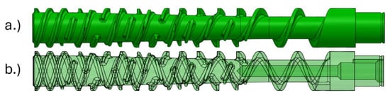
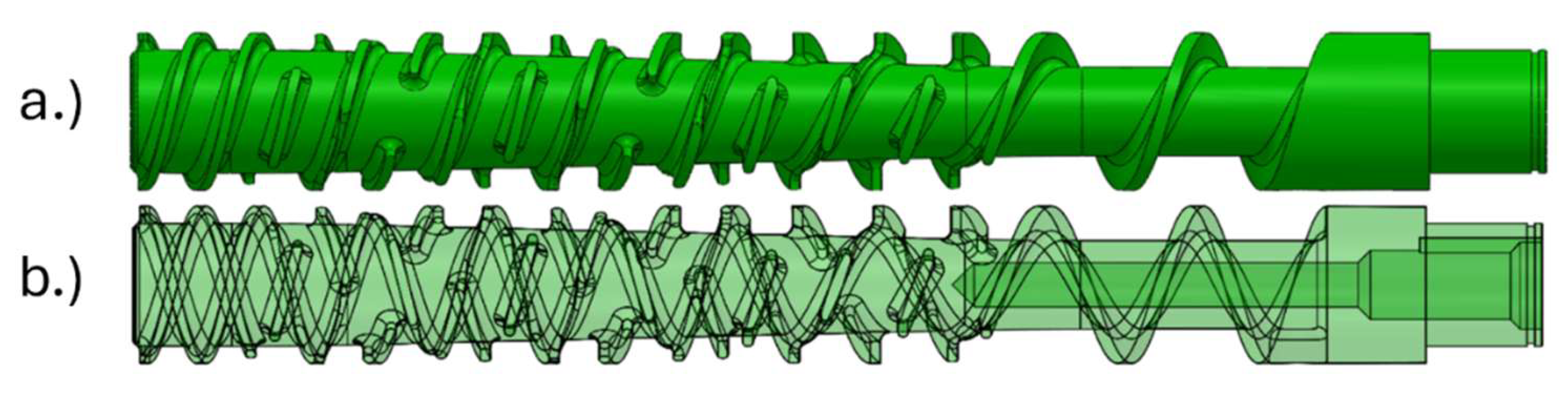
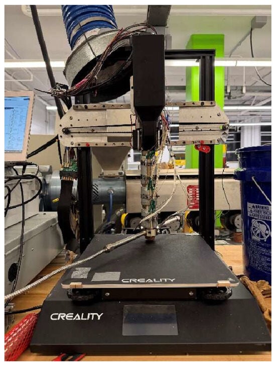
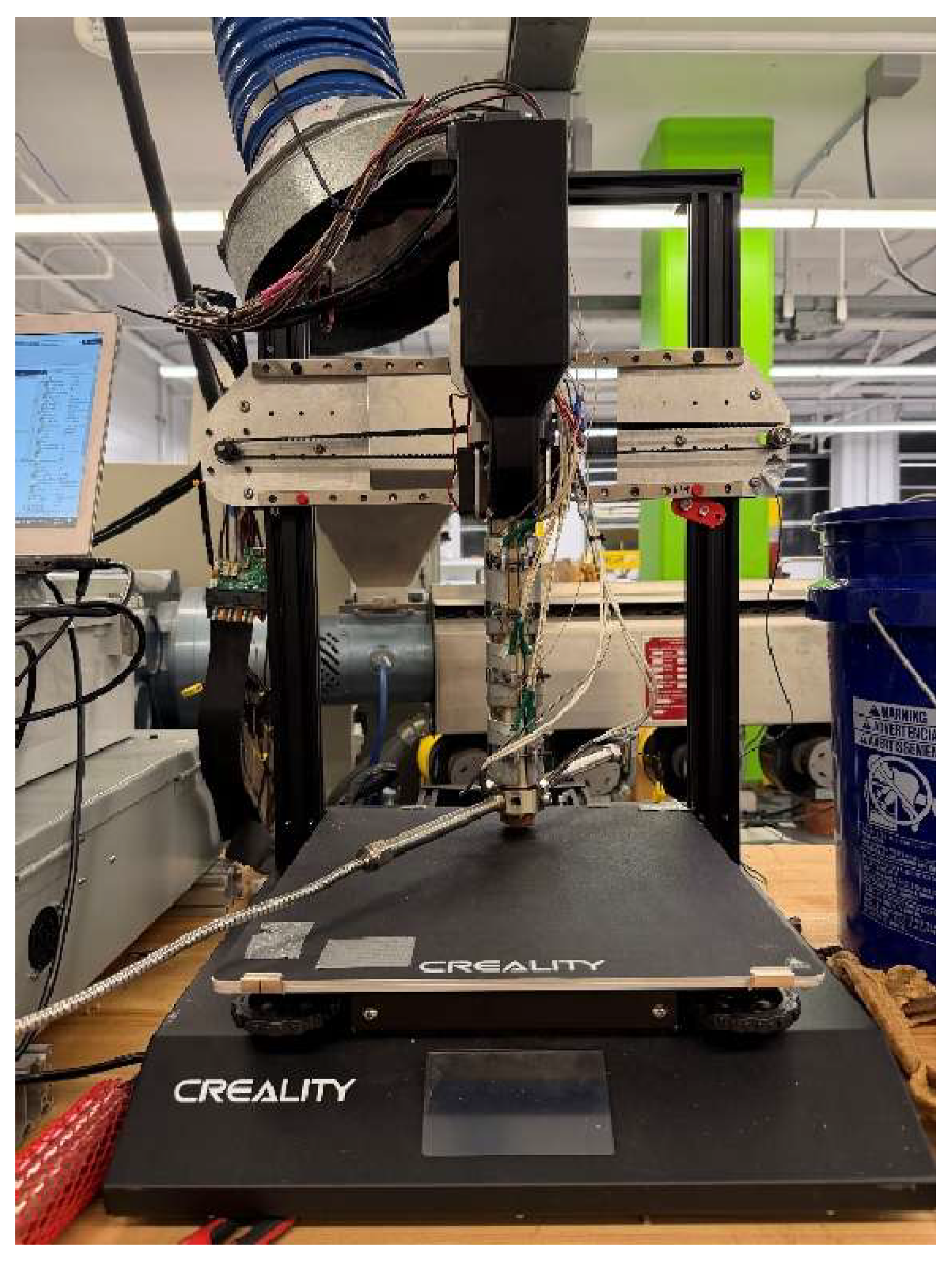
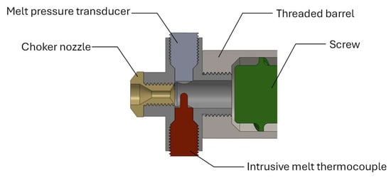
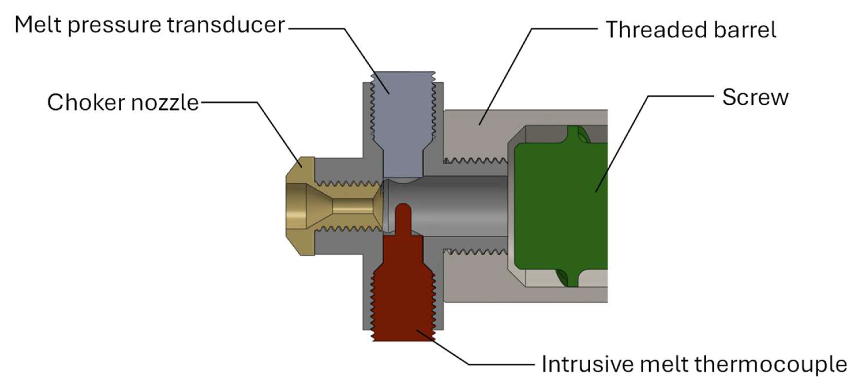
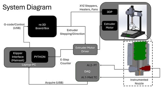
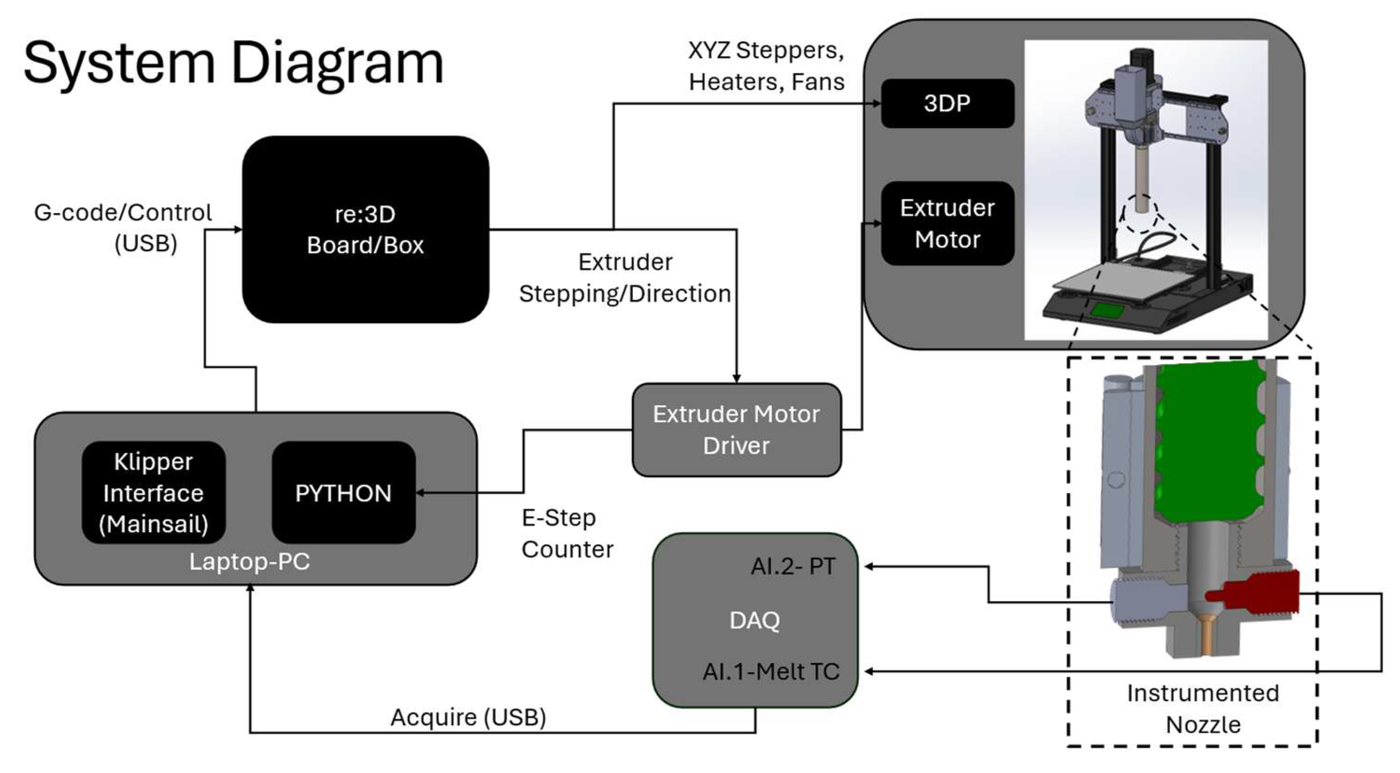
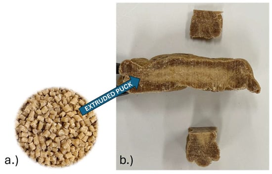
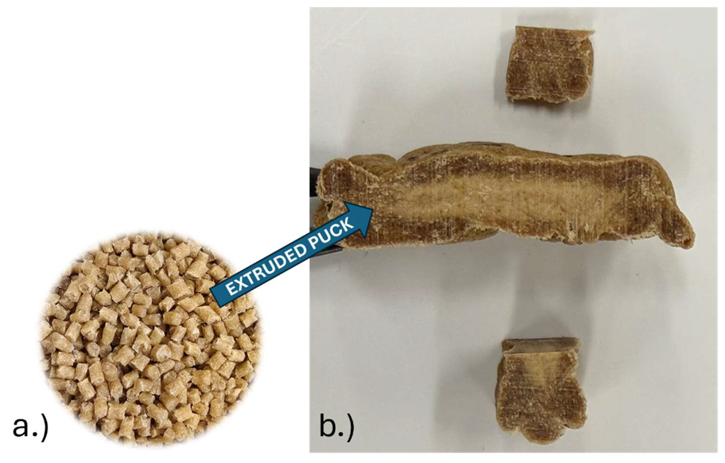
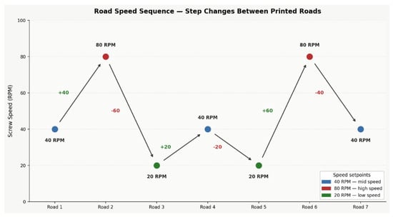
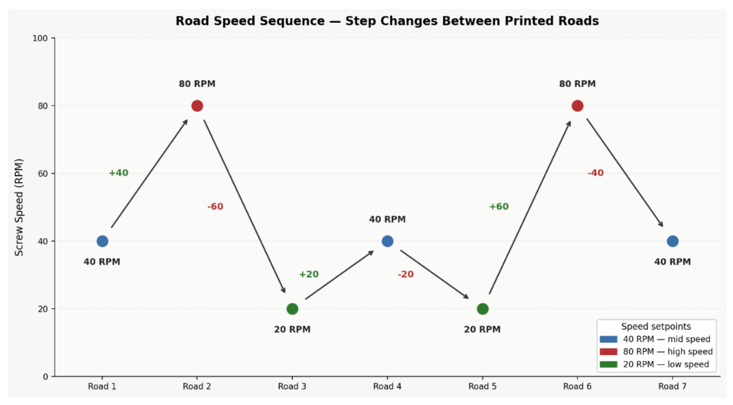
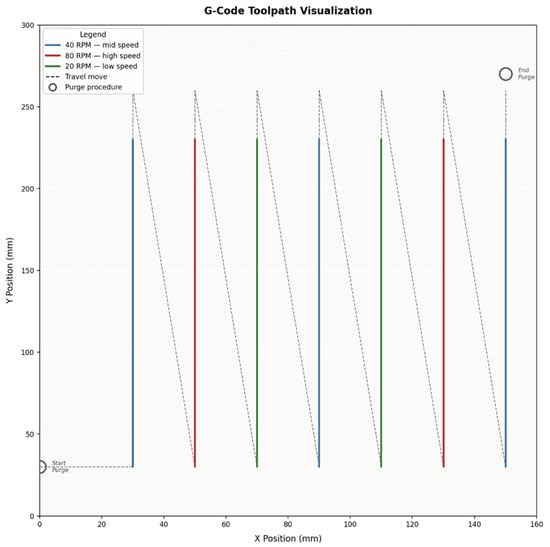
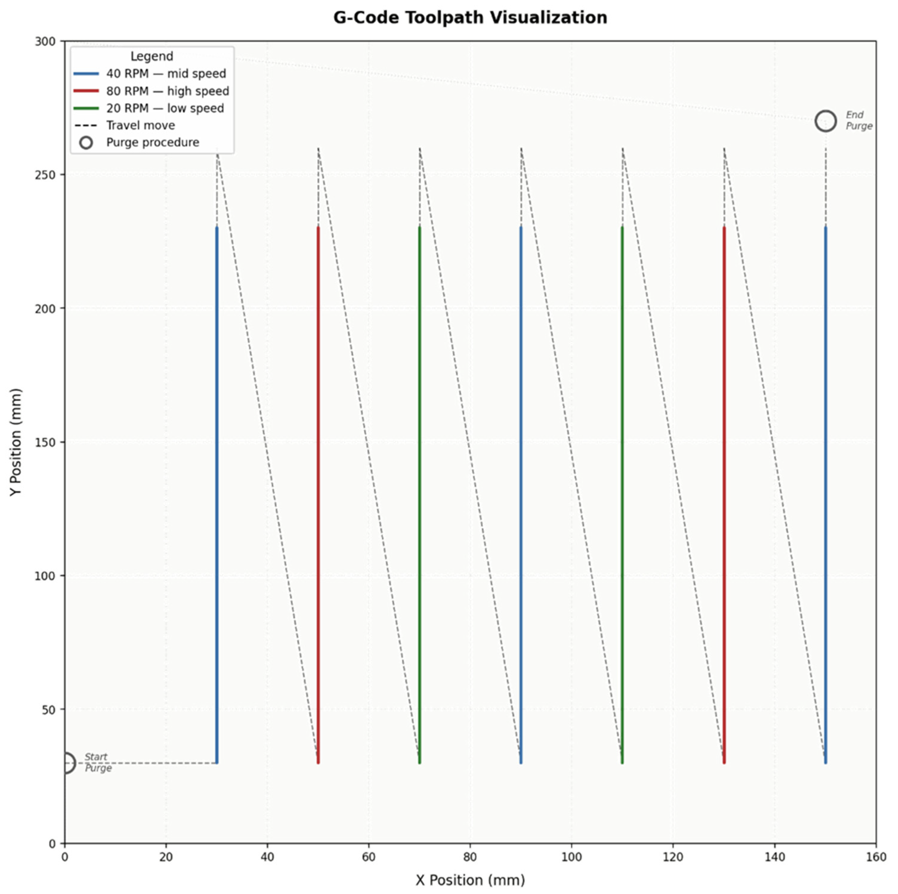
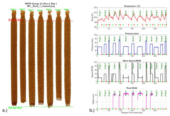
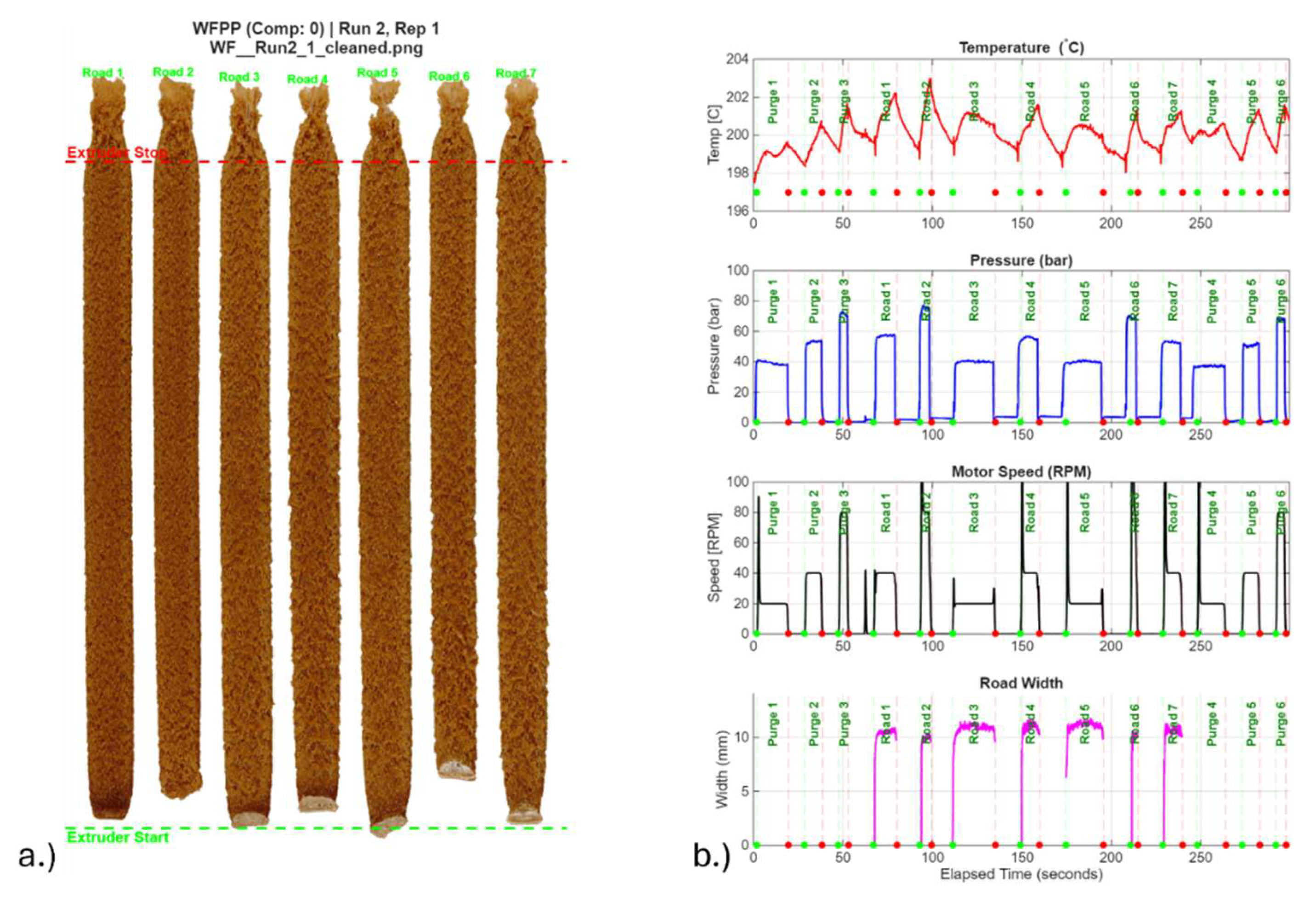
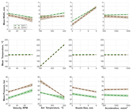
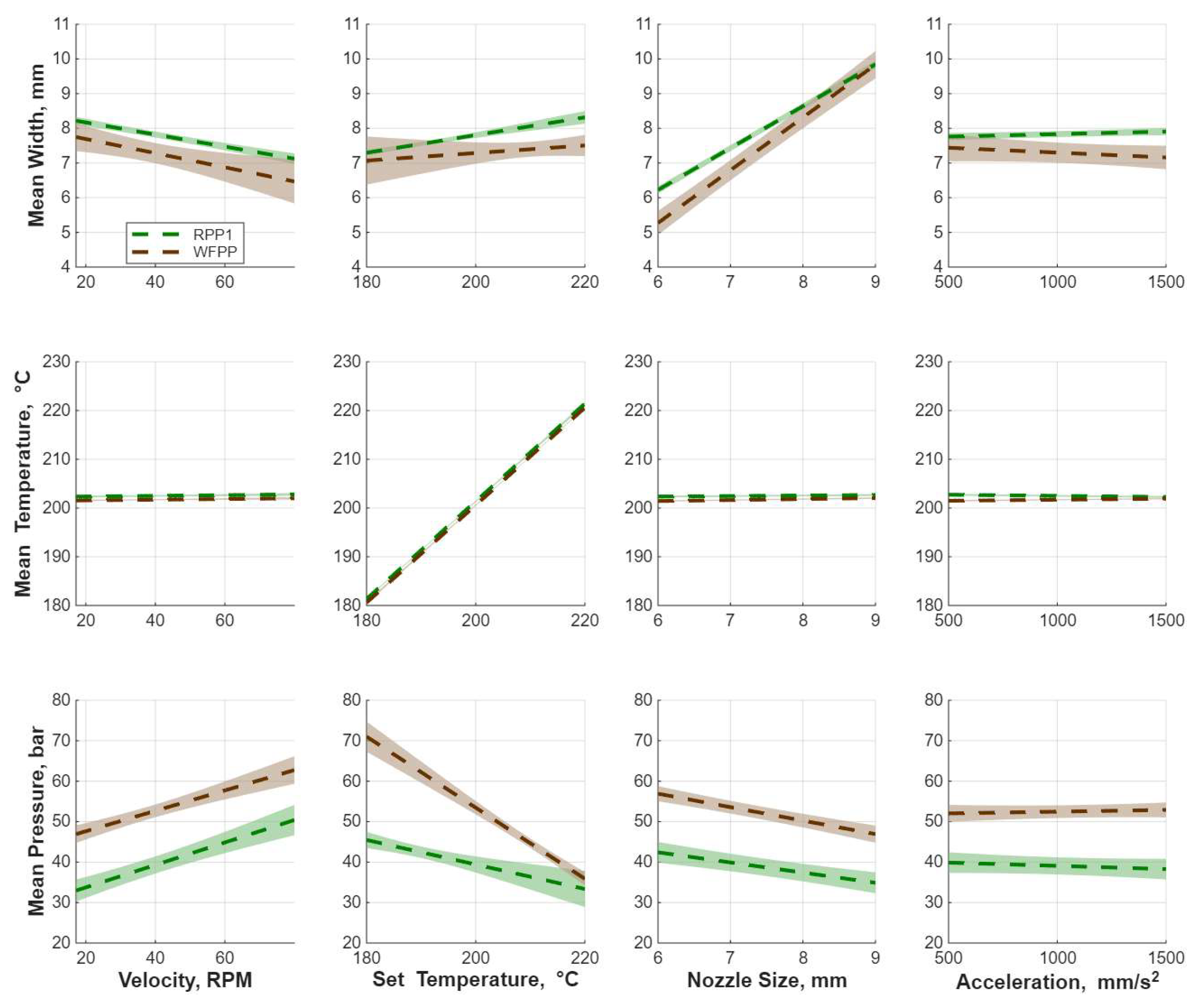
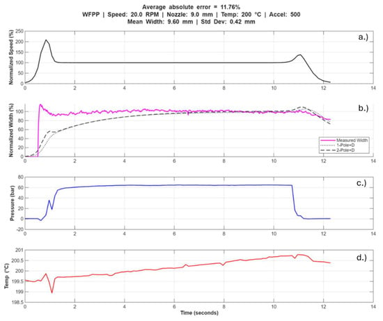
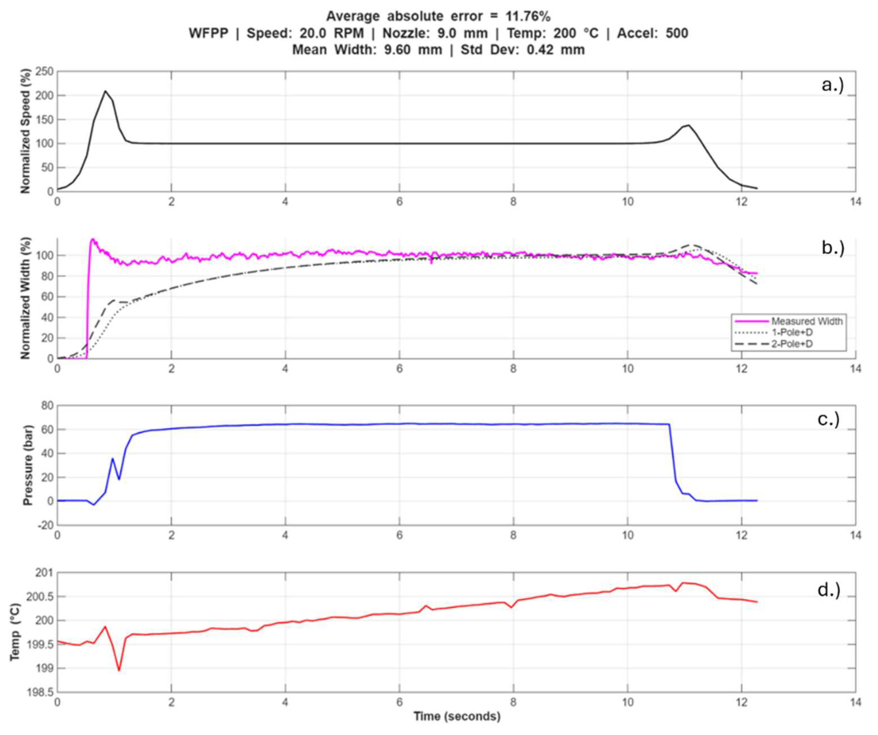
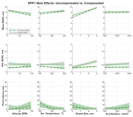
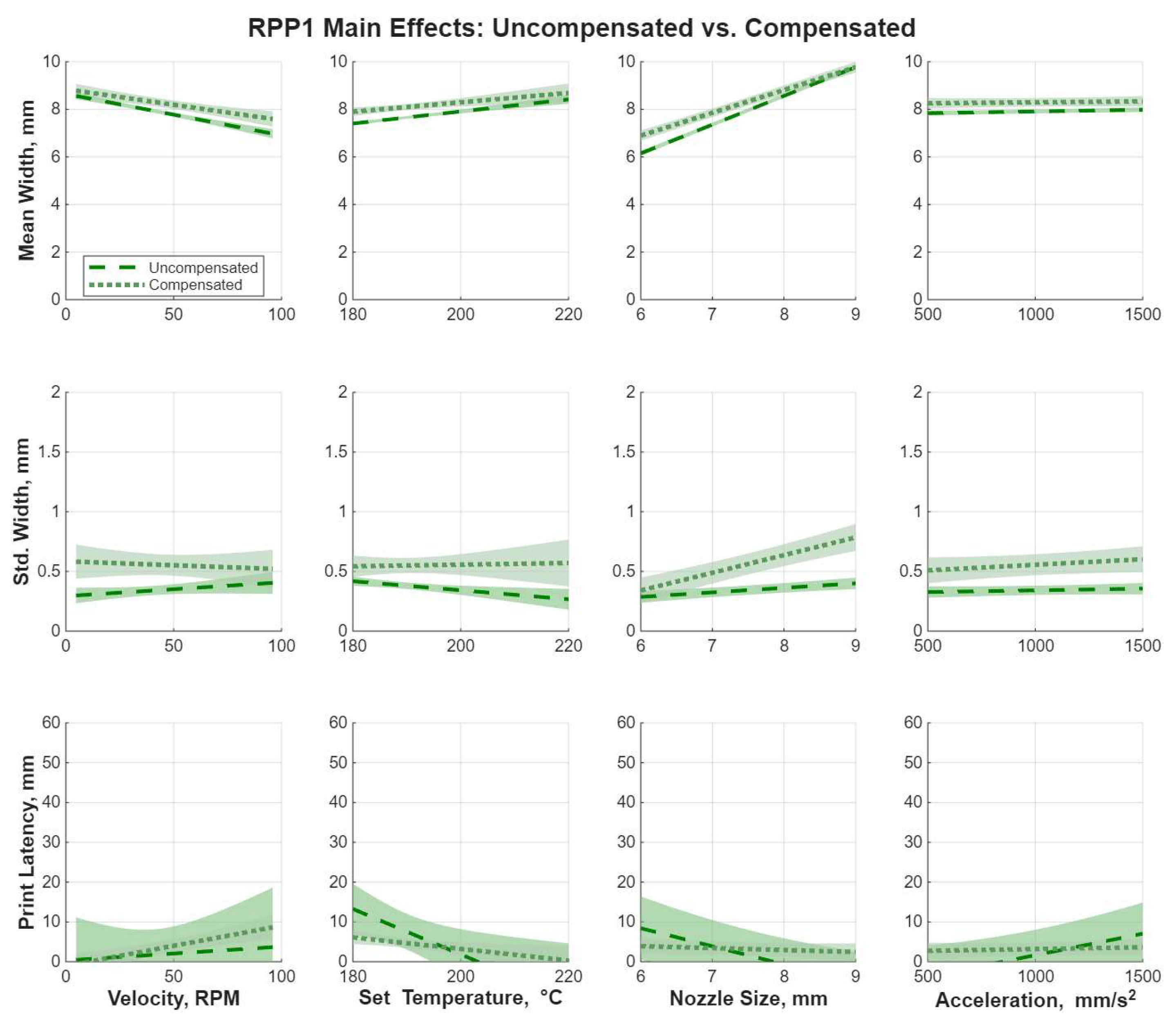
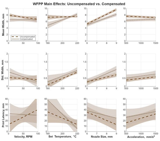
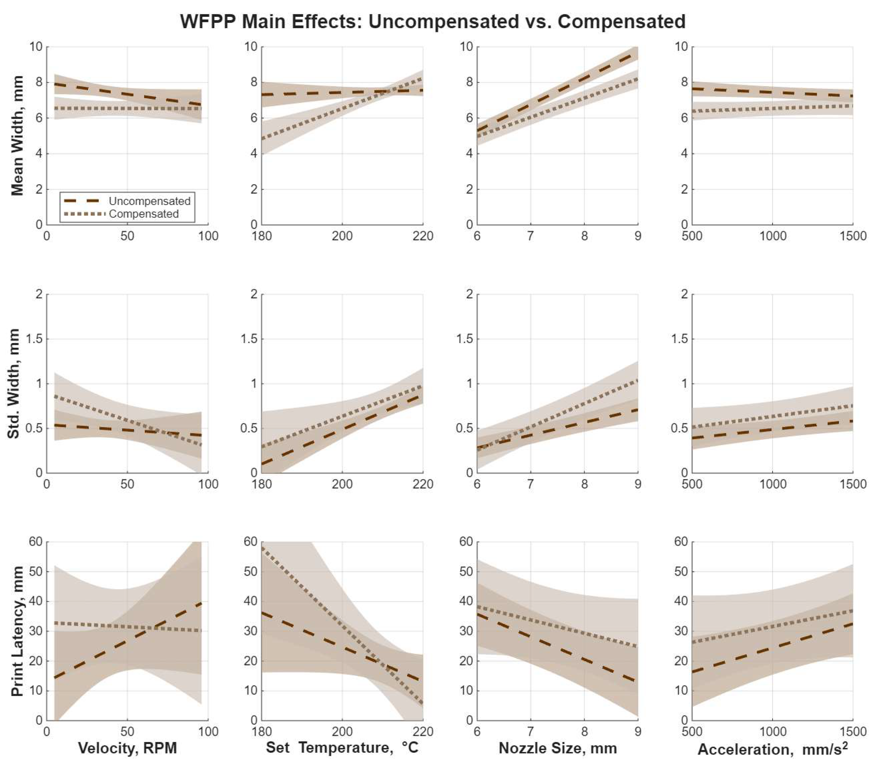
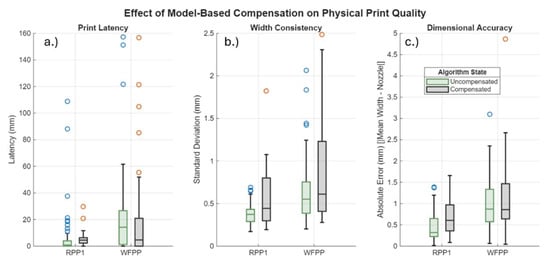
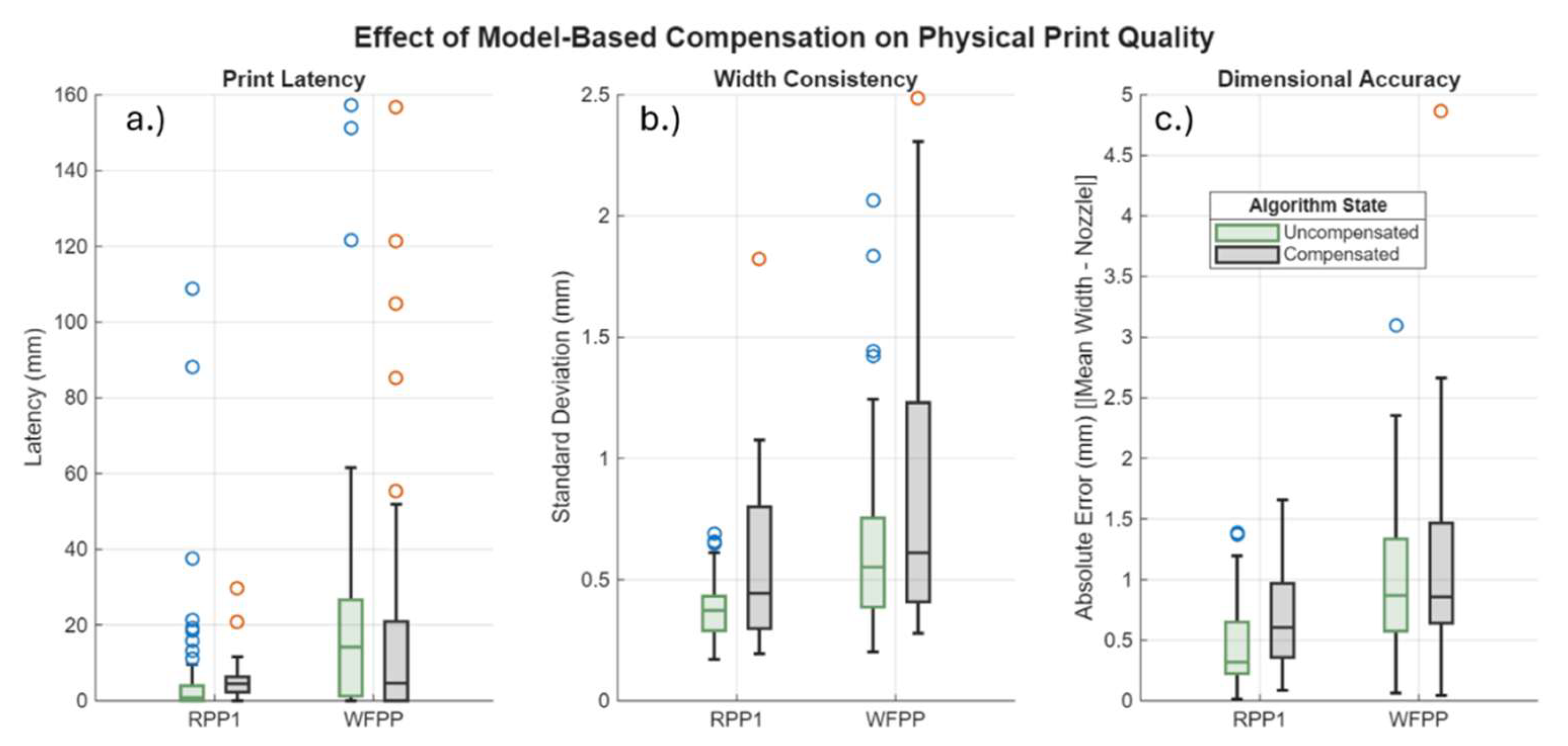
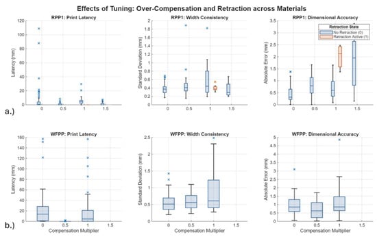
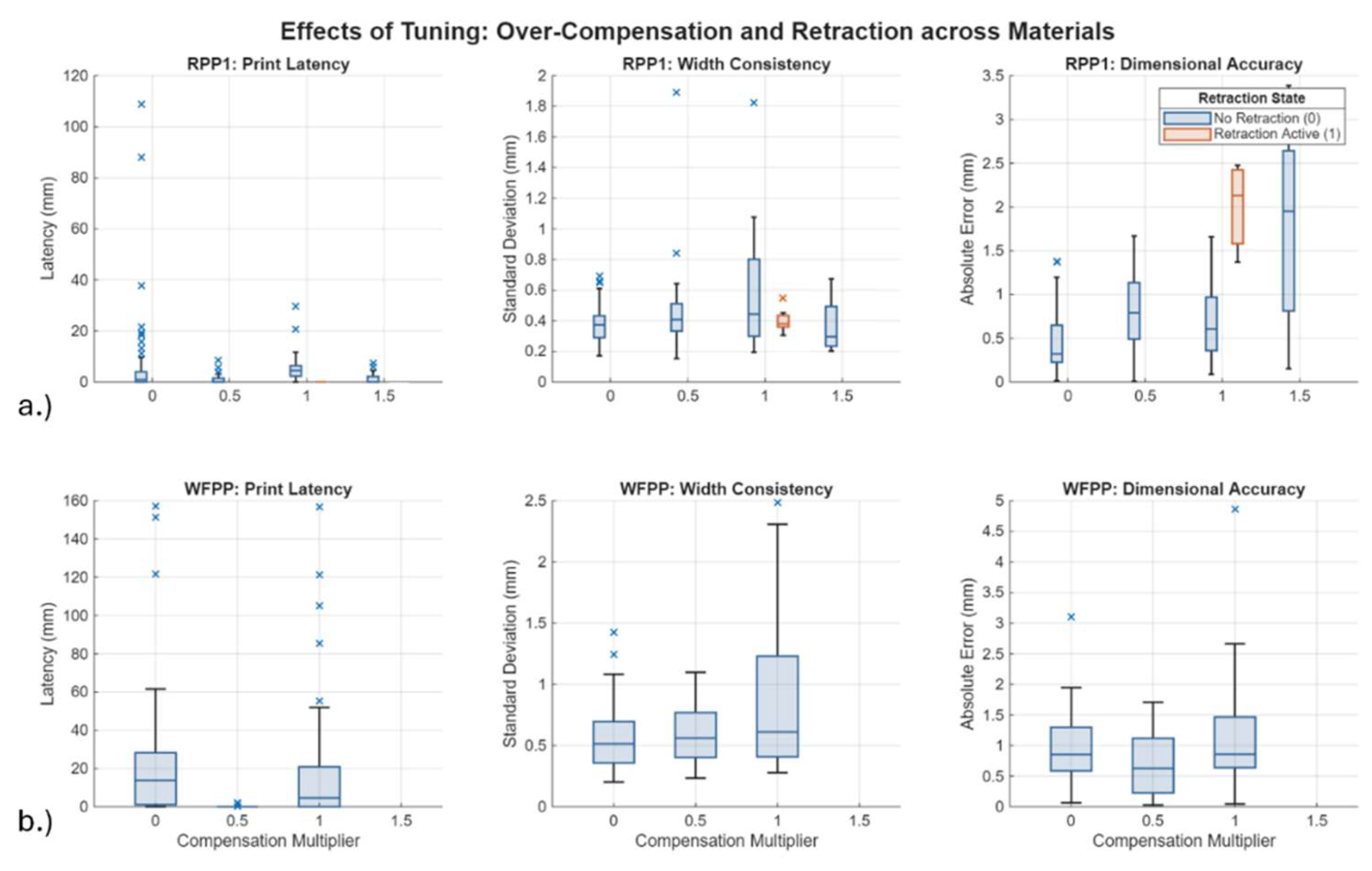

Disclaimer/Publisher’s Note: The statements, opinions and data contained in all publications are solely those of the individual author(s) and contributor(s) and not of MDPI and/or the editor(s). MDPI and/or the editor(s) disclaim responsibility for any injury to people or property resulting from any ideas, methods, instructions or products referred to in the content. |
© 2026 by the authors. Licensee MDPI, Basel, Switzerland. This article is an open access article distributed under the terms and conditions of the Creative Commons Attribution (CC BY) license.