


Abstract
Laser brazing is commonly used for joining visible automotive body panels where both mechanical integrity and surface quality are required. The present work addresses optimization of a robotic laser brazing workstation intended for prototype vehicle production. During initial commissioning, irregular braze formation was associated with unstable filler wire feeding. Therefore, the wire feeding system was modified and subsequently evaluated together with the influence of laser power and wire feed speed on joint quality under a constant robot travel speed. Experimental joints were produced from electrolytically galvanized DC06 steel using CuSi3Mn1 filler wire. Joint performance was assessed by tensile testing and metallographic examination. Tensile strengths between 293 and 314 MPa were obtained, while fracture occurred exclusively in the base material outside the brazed region. Metallographic observations revealed regular braze geometry for parameter sets A, B and D, whereas excessive thermal input resulted in blowhole formation, zinc coating degradation and enlargement of the heat-affected zone. Quantitative evaluation showed a nearly linear increase in the HAZ area with increasing delivered energy (R2 = 0.982). The results indicate that stable brazing conditions can be achieved through an appropriate balance between laser power and wire feed speed under constant robot travel speed conditions. The proposed parameter limits may serve as a practical guideline for robotic laser brazing of thin galvanized automotive sheets under prototype production conditions.
1. Introduction
Automotive body manufacturing relies on joining technologies that must simultaneously ensure structural integrity, dimensional accuracy, corrosion resistance, and surface quality. Resistance spot welding (RSW) remains the dominant joining method for load-bearing body structures due to its high productivity and suitability for large-scale manufacturing, where several thousand weld spots may be applied per vehicle [1,2]. However, increasing demands for lightweight construction, visible exterior surfaces, and multi-material body concepts have accelerated the implementation of advanced joining technologies in automotive production [3,4,5]. Recent developments indicate growing interest not only in laser-assisted joining methods but also in hybrid concepts combining welding and adhesive bonding to improve stiffness, fatigue resistance, and joining performance in dissimilar-material assemblies [6].
Among advanced joining technologies, laser processing has attracted considerable attention due to its high energy density, reduced thermal distortion, and excellent process controllability [3,7]. Laser technologies are particularly suitable for visible automotive body joints where strict requirements are imposed on surface appearance and corrosion resistance [7,8]. Experimental investigations of disk laser joining demonstrated favorable mechanical and structural properties of joined automotive sheets, supporting wider industrial implementation of laser-based technologies [9]. Unlike conventional laser welding, laser brazing is based on selective melting of the filler material while minimizing melting of the base material, thereby reducing thermal influence and preserving dimensional stability [10].
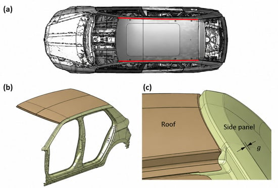
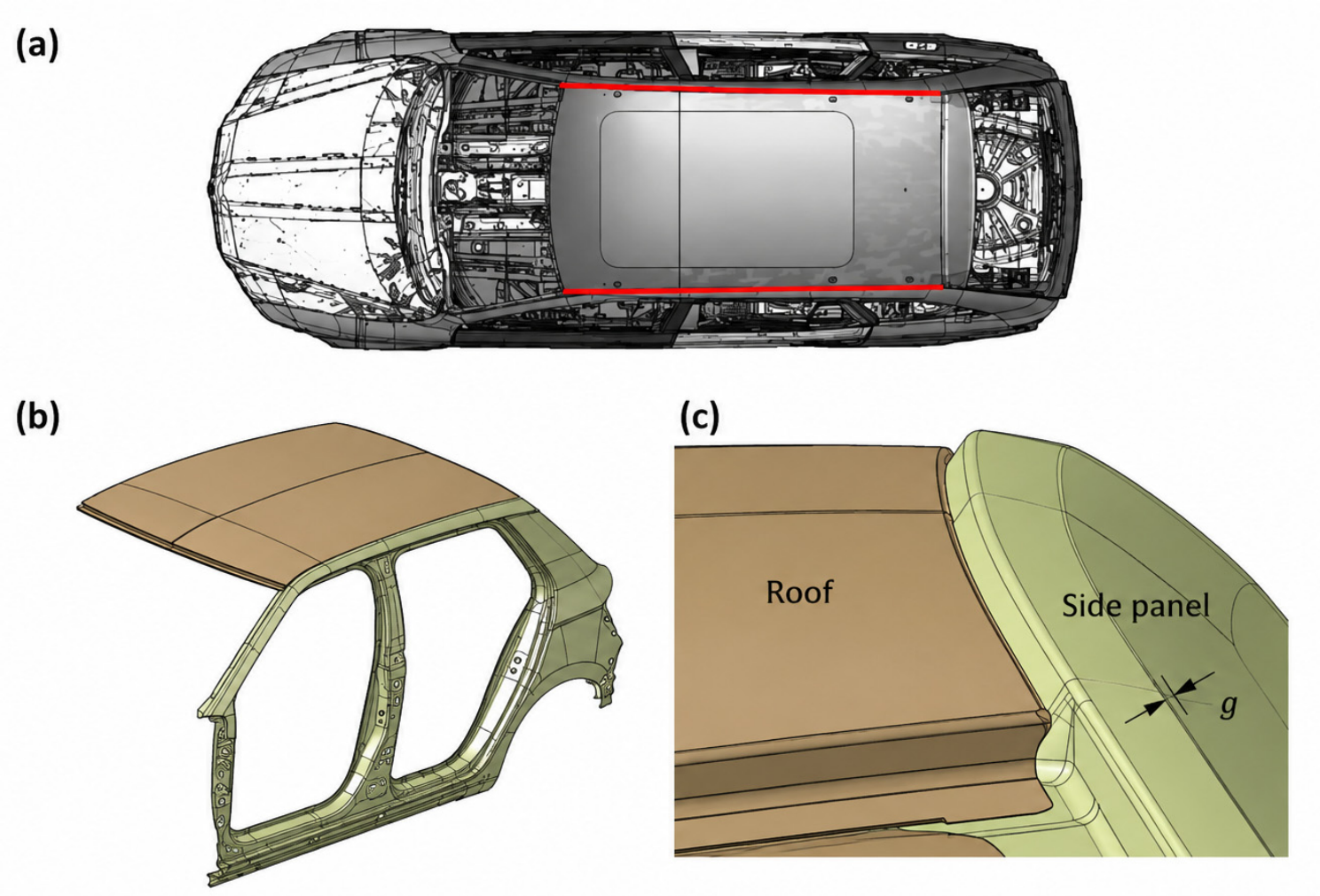
Laser brazing has become an established manufacturing technology for joining galvanized automotive body panels, particularly roof-to-side-frame assemblies and other visible exterior joints [7,11]. Compared with fusion welding, laser brazing provides improved surface quality, lower post-processing requirements, and reduced degradation of protective zinc coatings [12]. The wetting mechanism during laser brazing strongly depends on coating characteristics, and previous studies demonstrated that electrolytically galvanized sheets exhibit more favorable wetting behavior and lower susceptibility to porosity formation than hot-dip galvanized steels [12,13]. Structural investigations of laser-processed zinc-coated advanced steels further confirmed that thermal input significantly affects joint morphology, microstructural evolution, and local mechanical performance, emphasizing the importance of thermal process control [14]. Laser brazing is commonly applied to roof-to-side-panel assemblies in automotive body production, which represents the investigated joint configuration considered in this study (Figure 1).
Figure 1.
Investigated roof-to-side-panel laser brazing configuration: (a) location of the laser-brazed joint within the vehicle body, (b) CAD model of the joined roof and side-panel components, and (c) detail of the joint geometry with the inter-sheet gap (g).
The selection of filler material and process parameters plays a decisive role in laser brazing performance. CuSi3Mn1 filler wire (ERCuSi-A according to EN ISO 24373) is widely used for automotive applications because its relatively low melting temperature enables selective braze melting while preserving the integrity of the steel substrate [15]. Previous investigations reported that optimized laser-brazed joints may achieve mechanical properties comparable to or exceeding those of the base material while maintaining favorable corrosion resistance [16,17,18]. The dominant operating variables include laser beam power (P), wire feed speed (vp), and robot travel speed (vr), whose interaction determines the overall energy balance and directly influences wetting behavior, heat-affected zone (HAZ) development, joint geometry, and defect formation [12,19,20]. Additional studies demonstrated that parameter interactions influence not only strength and morphology but also local thermal accumulation and process stability, requiring integrated rather than independent parameter adjustment [21,22,23,24].
Previous studies addressed laser brazing optimization using statistical methods, data-driven approaches, and predictive modelling techniques [21,22,23,24,25]. Despite progress in process modelling and parameter selection, process stability is additionally affected by technological and mechanical factors associated with robotic implementation. In particular, stable filler wire transport is essential because irregular feeding may lead to non-uniform braze deposition, local overheating, interruption of wetting conditions, and deterioration of joint quality [26,27]. Existing studies addressing wire feeding and robotic laser brazing predominantly focus on serial production environments. In contrast, the influence of workstation-related factors under prototype production conditions has received substantially less attention [26,27,28].
More generally, laser joining technologies require close control of laser–material interaction, process stability, defect formation, and automated implementation in automotive applications [1,7,29].
Prototype manufacturing introduces additional challenges associated with low production volumes, variable body geometries, flexible fixturing, and frequent parameter adaptation. Under such conditions, maintaining stable laser brazing quality requires not only optimization of process parameters but also elimination of mechanical sources of variability arising from workstation configuration and filler material handling. Therefore, experimentally validated process criteria suitable for flexible prototype production remain necessary.
Therefore, the aim of this study was: (1) to identify and eliminate the mechanical cause of joint non-uniformity through redesign of the filler wire feeding system; (2) to evaluate the influence of laser power and wire feed speed on the mechanical and metallographic quality of laser-brazed joints under a constant robot travel speed produced from electrolytically galvanized DC06 steel using CuSi3Mn1 filler wire; and (3) to formulate a practical proportional parameter scaling criterion applicable to prototype production conditions.
2. Materials and Methods
2.1. Workstation Description
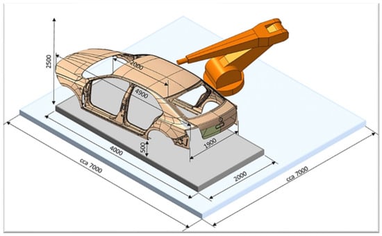
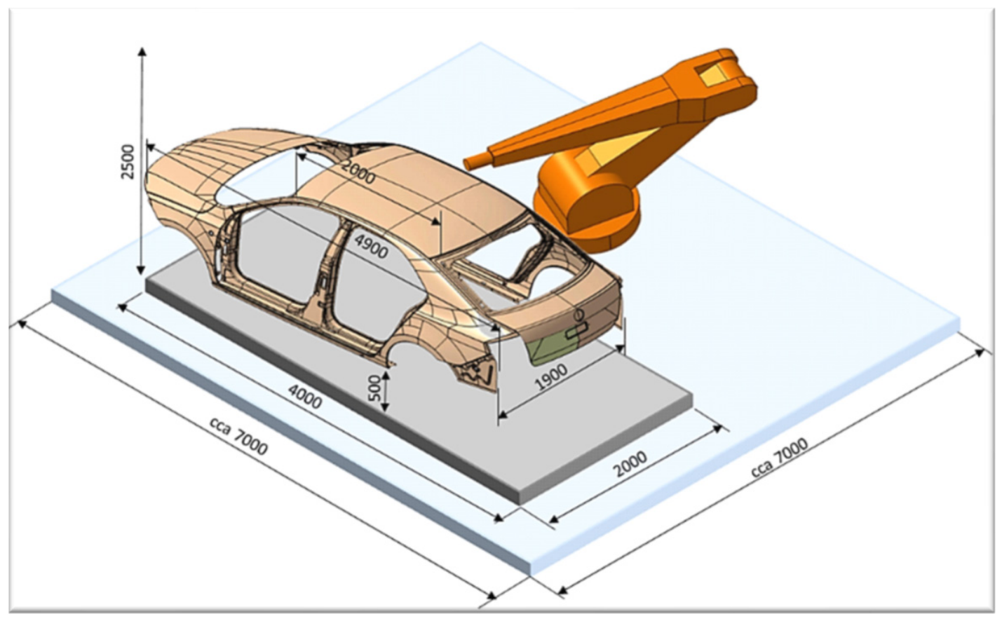
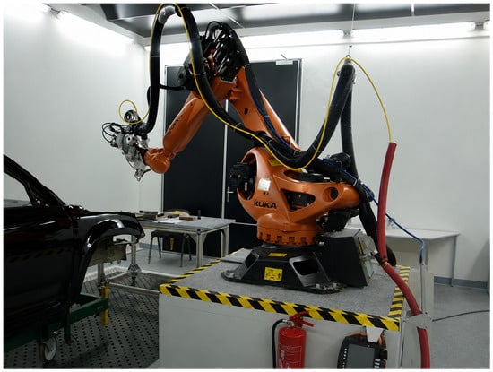
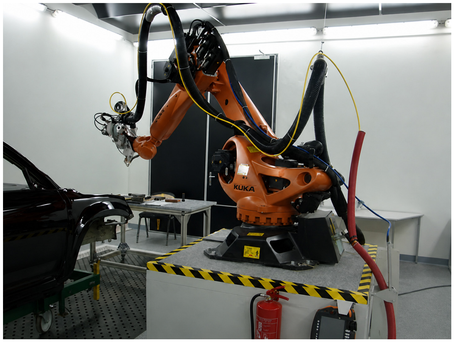
The robotic laser brazing workstation was developed for prototype automotive body production with a projected throughput not exceeding two body assemblies per day. The workstation was installed inside an enclosed laser processing cabin to ensure operator safety during laser operation; process monitoring and control were performed remotely from an adjacent control room. The main handling system consisted of an industrial robot KR 210 R2700 extra (KUKA AG, Augsburg, Germany) with a nominal payload capacity of 210 kg. The laser brazing head was mounted directly to the robot flange, enabling controlled positioning during continuous roof joint processing. The body assembly was fixed onto a steel base plate (4000 × 2000 mm2) with a plasma-nitrided surface using adjustable quick-release clamping elements. Due to geometric limitations of the roof clamping fixture and collision risk at extreme robot positions, brazing of the roof joint was performed sequentially from both vehicle sides. After completion of one side, the body was released and rotated to allow access to the opposite joint. Considering the low production volume typical of prototype manufacturing, this operation did not represent a limiting factor for workstation productivity. The overall configuration of the robotic laser brazing workstation and the arrangement of the main technological components are shown in Figure 2. Control of the roof laser brazing process was implemented by dividing the brazing path into individual process sections. Each section was characterized by three primary process variables that directly influence joint quality: laser beam power P [W], wire feed speed vp [m·min−1], and robot travel speed vr [m·min−1].
Figure 2.
Schematic layout of the robot workstation.
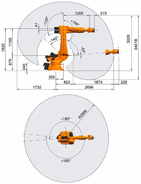
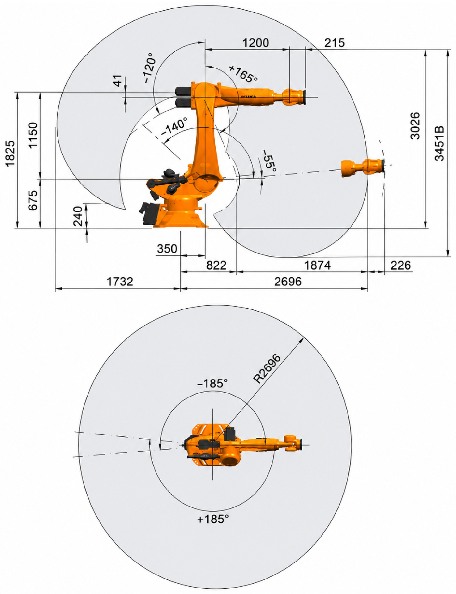
The parameter values assigned to individual sections were established during preliminary industrial optimization trials to achieve the quality requirements defined by the internal production standard. These optimized settings subsequently served as the basis for selecting experimental parameter sets. The available robot working envelope and its kinematic limitations during roof joint processing are illustrated in Figure 3.
Figure 3.
Robot working range.
During initial commissioning, non-uniform braze deposition and repeated burn-through of the base material were identified. The cause was the unsuitable position of the filler wire spool, placed on a fixed stand outside the robot, which required guiding the wire through a protective liner over several meters. During rotational robot movements, excessive friction and intermittent wire jamming occurred, resulting in unstable filler wire feeding and local deterioration of joint quality [15]. Consistent wire feed is a prerequisite for reproducible laser brazing performance [15,24,30]. The original position of the filler wire spool and the corresponding wire feeding arrangement are shown in Figure 4.
Figure 4.
Original position of the filler wire spool and wire feeding arrangement.
2.2. Wire Feed System Optimization
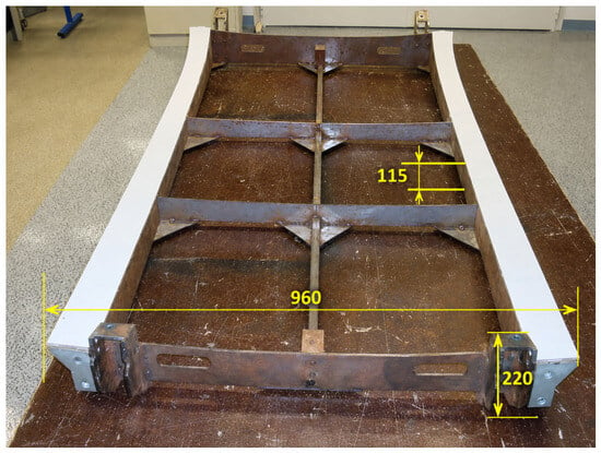
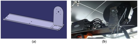
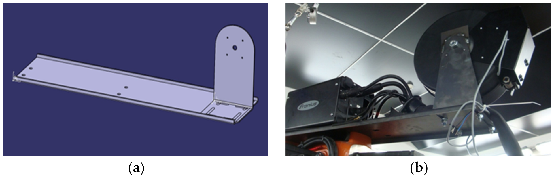
To eliminate this issue, a new wire spool holder was designed and installed directly on the robot’s upper arm in close proximity to the wire feeder motor, thereby minimizing the wire transport distance and eliminating the need for the protective liner. Similar approaches based on shortening the wire path and reducing feeding resistance have been reported as effective measures for improving robotic brazing stability [15]. The roof clamping fixture and the spatial constraints affecting robot movement during brazing are shown in Figure 5.
Figure 5.
Roof welding fixture and spatial constraints during robotic brazing.
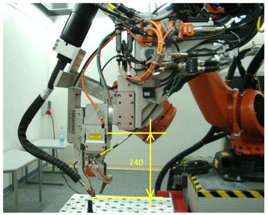
The configuration of the laser brazing head used during the experiments and its principal dimensions are shown in Figure 6.
Figure 6.
Laser brazing head and principal dimensions.
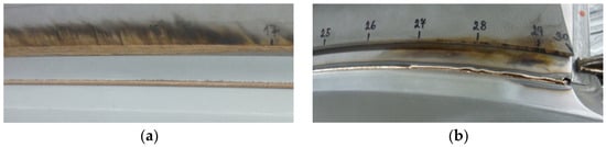
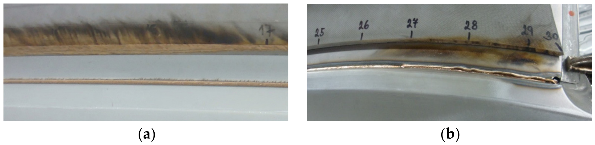
In the original workstation configuration, the spool arrangement resulted in an unnecessarily long wire transport path through the protective liner, increasing friction and causing occasional wire jamming during robot movements. To reduce feeding resistance, a new spool holder was designed and positioned directly on the robot’s upper arm in close proximity to the wire feeder motor, thereby shortening the wire transport path and eliminating the need for the protective liner. The redesigned holder and its implementation are shown in Figure 7. The resulting effect on joint appearance is presented in Figure 8.
Figure 7.
Redesigned wire spool holder: (a) CAD model of the holder with mounting plate; (b) implemented holder mounted on the robot’s upper arm.
Figure 8.
Joint appearance before and after spool relocation: (a) original configuration; (b) optimized configuration.
2.3. Base Material
Experimental specimens were manufactured from low-carbon deep-drawing steel DC06 in accordance with EN 10130:2006 [21]. The joined assembly consisted of a 0.8 mm thick roof panel and a 0.7 mm thick side frame. The sheets were supplied in the electrolytically galvanized condition according to EN 10152 [22]. The nominal chemical composition and specified mechanical properties of the base material are summarized in Table 1 and Table 2.
Table 1.
Chemical composition of DC06 steel according to EN 10130:2006 [21] (wt.%), balance Fe.
Table 2.
Specified mechanical properties of DC06 steel according to EN 10130:2006 [21].
The mechanical properties of the DC06 base material were additionally verified by tensile testing in the rolling direction of 90°. The results are reported as mean ± standard deviation (n = 6) in Table 3. The experimentally determined values were in good agreement with the mechanical properties specified by the material supplier and the requirements of EN 10130:2006 [21].
Table 3.
Experimentally determined mechanical properties of DC06 (rolling direction 90°, n = 6).
2.4. Filler Material
CuSi3Mn1 bronze wire (Ø 1.6 mm), classified as ERCuSi-A according to EN ISO 24373:2018 [23], was used as the filler material for laser brazing experiments. The filler wire was supplied by UTP Schweißmaterial GmbH (Bad Krozingen, Germany). CuSi3Mn1 is commonly applied in automotive laser brazing of zinc-coated body sheets due to its favorable wetting characteristics and lower melting temperature compared with steel substrates [8,17]. The nominal properties of the filler wire are summarized in Table 4.
Table 4.
Nominal mechanical and thermal properties of CuSi3Mn1 filler wire according to EN ISO 24373:2018 [23].
2.5. Experimental Parameter Sets
Laser brazing experiments were performed using a TRUMPF laser source (TRUMPF GmbH + Co. KG, Ditzingen, Germany) integrated into the robotic workstation described in Section 2.1. Five experimental parameter sets (A–E) were prepared to evaluate the influence of laser beam power P [W] and wire feed speed vp [m·min−1]. The robot travel speed was maintained at 1.0 m·min−1 throughout the study and is reported in Table 5.
Table 5.
Experimental parameter sets used for evaluating the influence of laser power and wire feed speed at a constant robot travel speed.
The investigated parameter range was selected based on preliminary industrial optimization trials and values reported for comparable laser brazing configurations [10,13]. The parameter combinations were designed to cover the relevant processing window for laser power (P = 1000–1800 W) and wire feed speed (vp = 1.0–1.3 m·min−1) while maintaining a constant robot travel speed. Set B was considered the reference configuration. Parameter sets C and E represented increased energy input conditions expected to promote thermal overload and defect formation, whereas Set D was included to verify the lower process boundary.
Additional process parameters were maintained constant throughout all experiments. The nominal laser spot diameter was approximately 2.4 mm and the focal position was located at the sheet surface (0 mm defocus). Pure argon was used as shielding gas. The filler wire was fed at an angle of approximately 50° relative to the sheet surface, and the free wire extension between the wire guide tip and the brazing zone was maintained within the range of approximately 40–60 mm. The electrolytic zinc coating thickness of the DC06 sheets was approximately 5–7.7 μm per side according to the supplier specification.
2.6. Tensile Testing
Tensile tests were performed in accordance with EN ISO 6892-1:2019 [22] using a ZwickRoell Z250 universal testing machine (ZwickRoell GmbH & Co. KG, Ulm, Germany) with a maximum load capacity of 250 kN. The crosshead speed was set to v = 1 mm·min−1. Six specimens were tested for each of the selected parameter sets A and B.
The tensile specimens were extracted directly from the laser-brazed roof-to-side-panel assembly while preserving the original joint geometry. The specimen dimensions and loading configuration are shown in Figure 9. The specimen width was b0 = 45 ± 2 mm, the total length was l ≥ 65 mm, the free clamping length was l0 ≥ 95 mm, and the deformation-free zone was located 35 mm from the joint centreline.
Figure 9.
Geometry and dimensions of the tensile specimen extracted from the roof-to-side-panel laser-brazed assembly: specimen width b0 = 45 ± 2 mm, total length l ≥ 65 mm, free clamping length l0 ≥ 95 mm, and deformation-free zone located 35 mm from the joint centreline. Tensile testing was performed according to EN ISO 6892-1:2019 [22].
Engineering stress and strain were calculated according to Equations (1) and (2):
where
- σ—engineering stress [MPa],
- F—instantaneous tensile force [N],
- S0—initial cross-sectional area [mm2].
- ε—engineering strain [–],
- ΔL—instantaneous change in length [mm],
- L0—original gauge length [mm].
2.7. Metallographic Analysis
Metallographic analysis was performed to evaluate the morphology of laser-brazed joints and characterize the dimensions of the heat-affected zone (HAZ). The evaluated parameters included braze bead thickness, braze-to-sheet interface width, and HAZ area.
Specimens were sectioned perpendicular to the brazed joint under cooling conditions to minimize thermal and mechanical influence on the observed microstructure. The samples were mounted in phenolic resin (MultiFast, Struers A/S, Ballerup, Denmark) and prepared using standard metallographic grinding and polishing procedures.
Grinding and polishing were carried out using progressively finer abrasive media to obtain a surface suitable for microscopic observation. The polished specimens were chemically etched using 3% Nital (HNO3 in ethanol) to reveal the microstructure of the steel substrate and the brazed interface. Particular attention was paid to the evaluation of the HAZ and the occurrence of blowholes within the brazed region.
Metallographic observations were performed using an Olympus SZH10 stereomicroscope (Olympus Corporation, Tokyo, Japan) and evaluated using image analysis software.
3. Results
3.1. Tensile Test Results
Tensile testing was performed to evaluate the mechanical performance of laser-brazed joints and to determine the location of fracture relative to the brazed region. Fracture surfaces were visually inspected and subsequently examined using stereomicroscopy to identify the dominant failure mode.
For both tested parameter sets (A and B), fracture occurred outside the brazed region and propagated through the base material, indicating that the strength of the brazed joint exceeded the load-bearing capacity of the joined sheets. No fracture initiation within the braze or heat-affected zone was observed.
Representative tensile test results for parameter sets A and B are summarized in Table 6, Table 7 and Table 8.
Table 6.
Tensile test results—Set A (P = 1350 W, vp = 1.3 m·min−1, n = 6).
Table 7.
Tensile test results—Set B (P = 1100 W, vp = 1.0 m·min−1, n = 6).
Table 8.
Statistical evaluation of tensile test results for parameter sets A and B.
In all tested specimens, fracture occurred in the DC06 base material outside the brazed region. No crack initiation or crack propagation through the brazed seam was observed. The coefficients of variation remained below 2% for both parameter sets, indicating good process repeatability. The tensile tests primarily verified the integrity of the brazed joints and confirmed the absence of weak joints within the investigated process window rather than providing a direct comparison of joint strength between parameter sets.
3.2. Metallographic Analysis
Metallographic analysis of cross-sections from specimens A–E revealed pronounced differences associated with the applied energy input. Specimens A and B (P = 1350 W and 1100 W) exhibited a regular braze cross-section geometry with uniform silicon segregation channels and a continuous heat-affected zone (HAZ) without visible blowholes. The observed morphology indicates stable wetting conditions and satisfactory joint formation. Similar microstructural features have been reported for laser brazing of electrolytically galvanized steel sheets under optimized processing conditions [6,7].
In contrast, specimens C and E (P = 1650 W and 1800 W) exhibited severe blowhole formation, a convex braze profile, and extensive degradation of the zinc coating. These defects are characteristic of excessive thermal input during laser brazing and have been reported previously in comparable joining configurations [6,16,31]. Blowholes extending through the zinc-coated region may adversely affect the long-term corrosion resistance of the joint [26].
Although specimen B was produced using identical nominal process parameters, local variations in HAZ dimensions were observed. This behavior is likely related to local variations in the inter-part gap, which is known to influence heat distribution, wetting behavior, and braze geometry during laser brazing [17]. The observed increase in HAZ dimensions with increasing laser power is consistent with trends reported in the literature [18].
3.2.1. Parameter Set A—P = 1350 W
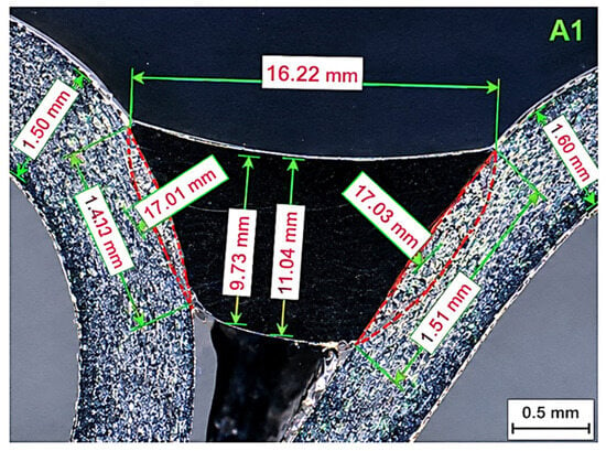
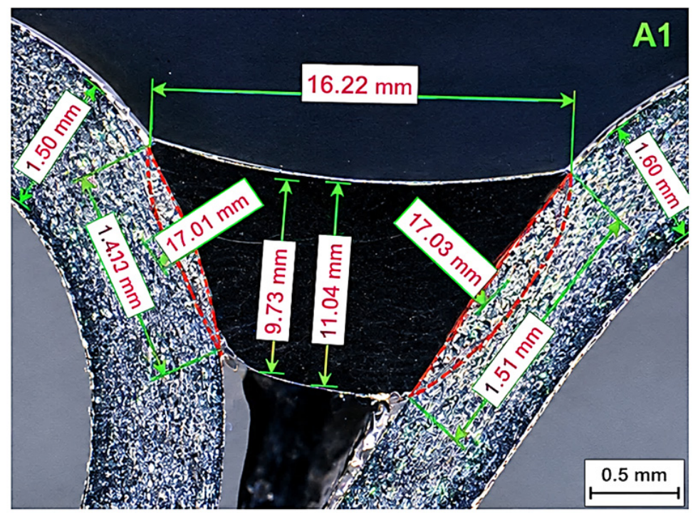
The metallographic cross-section of specimen A1 is shown in Figure 10. A regular concave braze profile with a continuous braze-to-sheet interface and characteristic segregation channels within the braze metal can be observed. No visible porosity, blowholes, or other metallurgical discontinuities were detected in the examined cross-section.
Figure 10.
Cross-section of specimen A1 (P = 1350 W) exhibiting a regular concave braze profile and characteristic segregation channels within the braze metal.
A detailed view of the transition region is presented in Figure 11. The heat-affected zone (HAZ) exhibited a continuous morphology and uniform width along the interface. The transition zones showed satisfactory wetting and continuous bonding between the braze metal and steel substrate. These observations indicate stable processing conditions and satisfactory joint formation.
Figure 11.
Detail of the braze-to-sheet transition zone in specimen A1, showing a continuous heat-affected zone (HAZ) without visible blowholes.
3.2.2. Parameter Set B—P = 1100 W
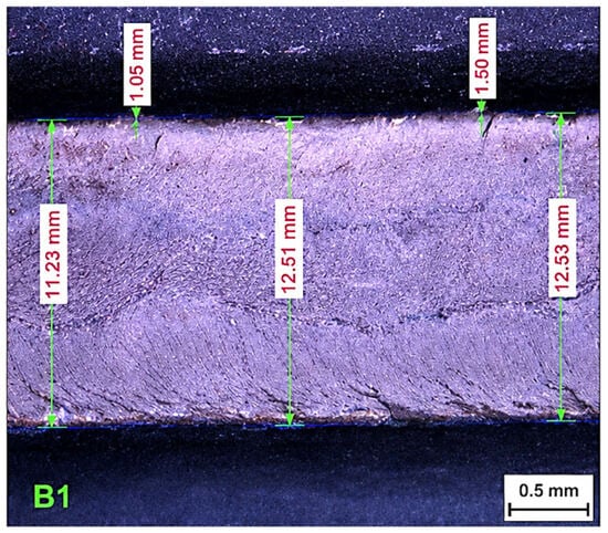
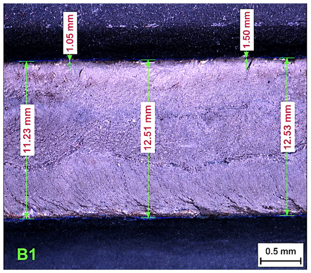
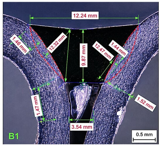
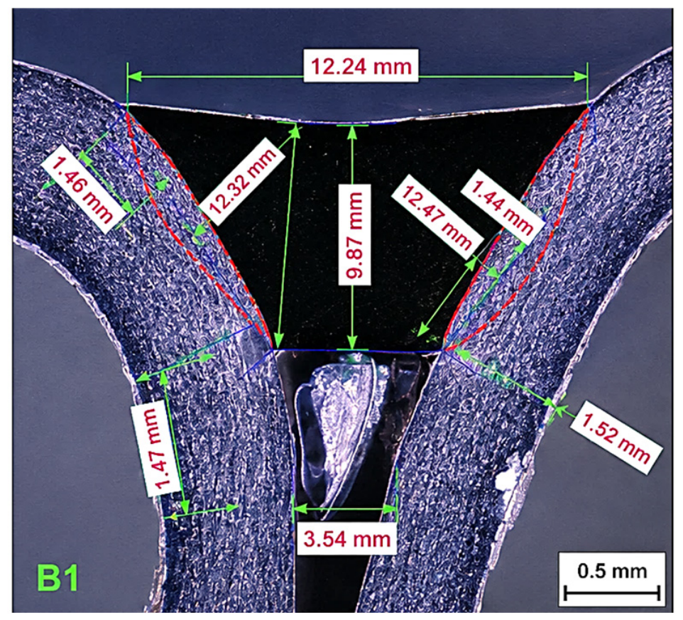
The cross-sectional morphology of specimen B1 is presented in Figure 12. The brazed joint exhibited a regular braze profile with characteristic segregation channels and only limited porosity. Compared with specimen A1, a slightly narrower HAZ was observed, which is consistent with the lower laser power applied.
Figure 12.
Cross-section of specimen B1 (P = 1100 W) showing a uniform braze profile with characteristic segregation channels in the braze metal.
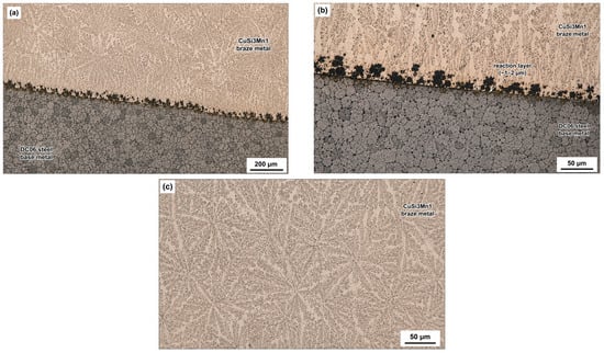
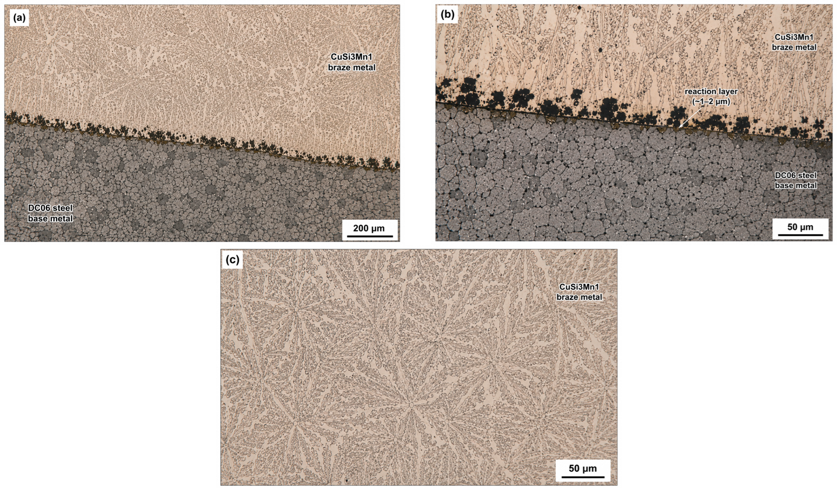
Figure 13 shows a detailed view of the braze-to-sheet transition zone. Although identical nominal process parameters were used, local variations in HAZ dimensions were observed between different cross-sections. This behavior is likely associated with local variations in the inter-part gap and minor fluctuations in heat distribution during the brazing process. No critical metallurgical defects were identified. The microstructure of the brazed joint is shown in Figure 14. The braze metal exhibited a typical dendritic microstructure characteristic of CuSi3Mn1 filler metal. A continuous interface between the braze metal and the DC06 substrate was observed without visible cracks or lack-of-bond defects. Only a thin reaction layer was present along the interface, indicating satisfactory metallurgical bonding under the selected process conditions.
Figure 13.
Detail of specimen B1 showing local variation in HAZ dimensions despite identical nominal processing parameters.
Figure 14.
Microstructure of the laser-brazed joint: (a) braze–steel interface; (b) detail of the interface region; (c) dendritic microstructure of the CuSi3Mn1 braze metal.
3.2.3. Comparison of Sets A and B—Macroscopic View
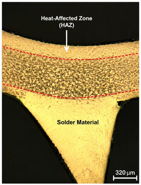
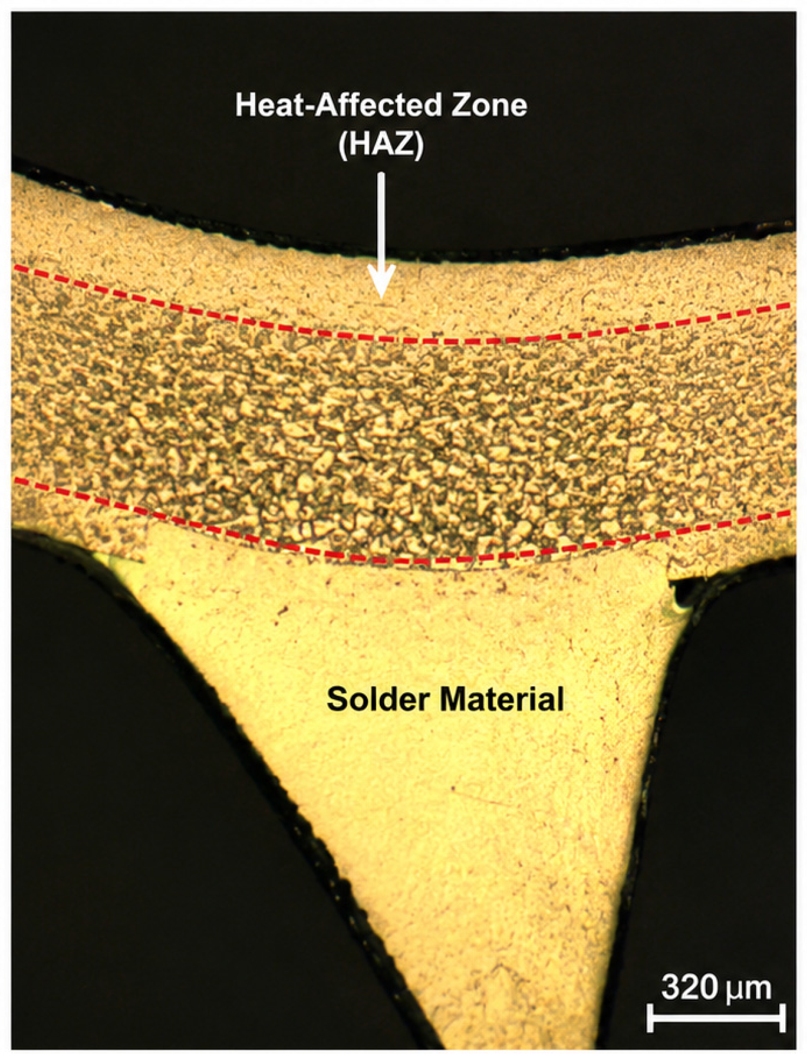
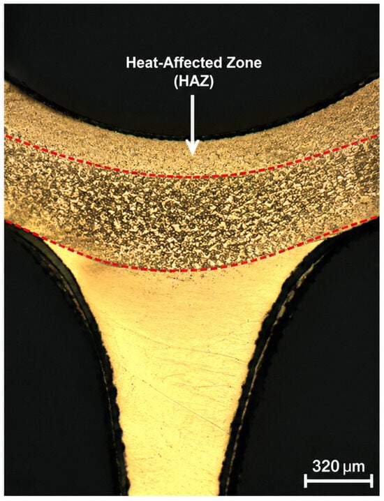
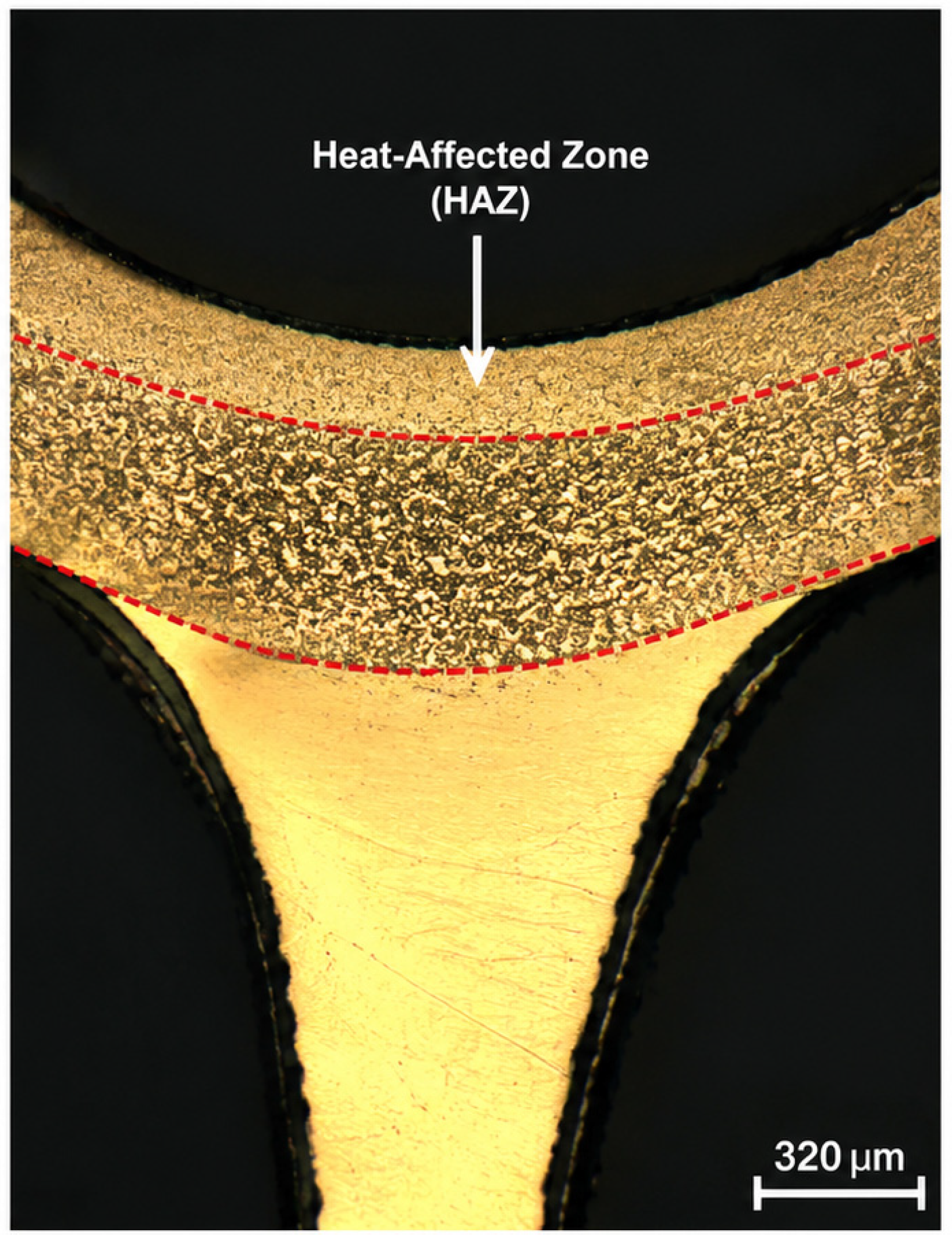
The macroscopic appearance of specimens A1 and B1 is shown in Figure 15 and Figure 16, respectively. Both joints exhibited a regular concave braze profile with continuous wetting along the braze-to-sheet interface and uniformly formed edges. No macroscopic defects, such as excessive braze overflow or surface irregularities, were observed.
Figure 15.
Macroscopic view of specimen A1 showing the heat-affected zone and braze material.
Figure 16.
Macroscopic view of specimen B1 showing the heat-affected zone and braze material.
As shown in Figure 15 and Figure 16, the heat-affected zone (HAZ) was wider in specimen A1 than in specimen B1. The measured HAZ area increased from 1.08 mm2 in specimen B1 to 1.52 mm2 in specimen A1, corresponding to the higher energy input applied during brazing (81.0 J·mm−1 versus 66.0 J·mm−1). This observation is consistent with the metallographic results presented in Figure 11 and Figure 13.
3.2.4. Heat-Affected Zone (HAZ) Area Evaluation
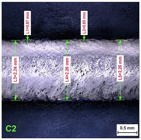
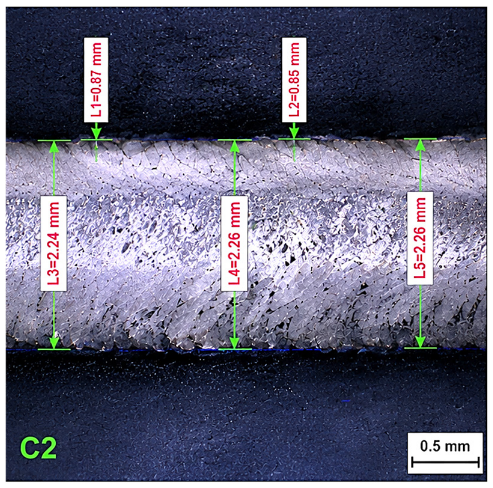
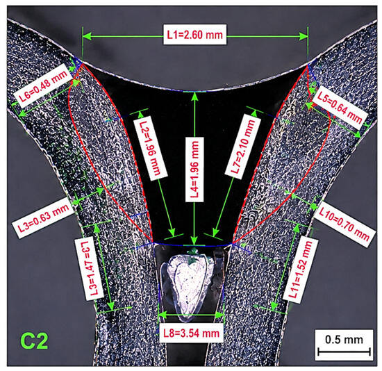
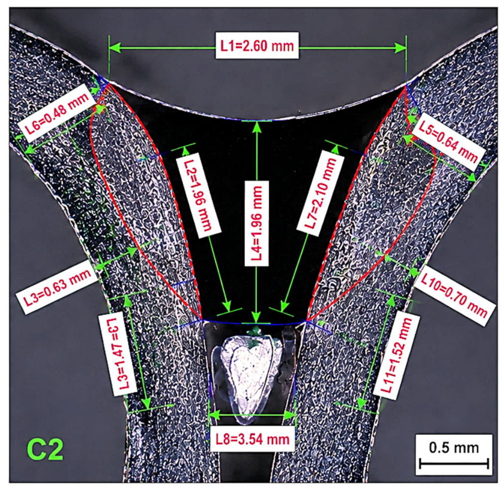
Figure 17 and Figure 18 show representative sections of specimen C2 used for quantitative evaluation of the heat-affected zone. The HAZ boundaries were identified based on the transition between the recrystallized region and the unaffected base material and subsequently measured using the calibration software of the Olympus SZH10 stereomicroscope. The measured HAZ area reached 2.71 ± 0.12 mm2, corresponding to the increased thermal input applied during brazing.
Figure 17.
Longitudinal cross-section of specimen C2 (P = 1650 W) used for quantitative evaluation of the heat-affected zone.
Figure 18.
Transverse cross-section of specimen C2 (P = 1650 W) showing the heat-affected zone boundaries used for area measurement.
3.2.5. Parameter Set C—P = 1650 W
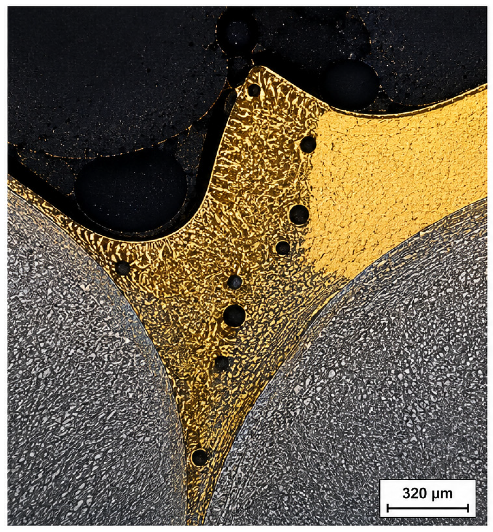
Figure 19 shows the cross-section of specimen C2 produced at a laser power of 1650 W. In comparison with parameter sets A and B, a pronounced change in joint morphology is evident. The braze profile became convex and several large blowholes were observed within the brazed region. Local degradation of the zinc coating can also be identified along the braze-to-sheet interface, indicating excessive thermal loading during the process.
Figure 19.
Cross-sectional morphology of specimen C2 (P = 1650 W) exhibiting severe blowhole formation and a convex braze profile.
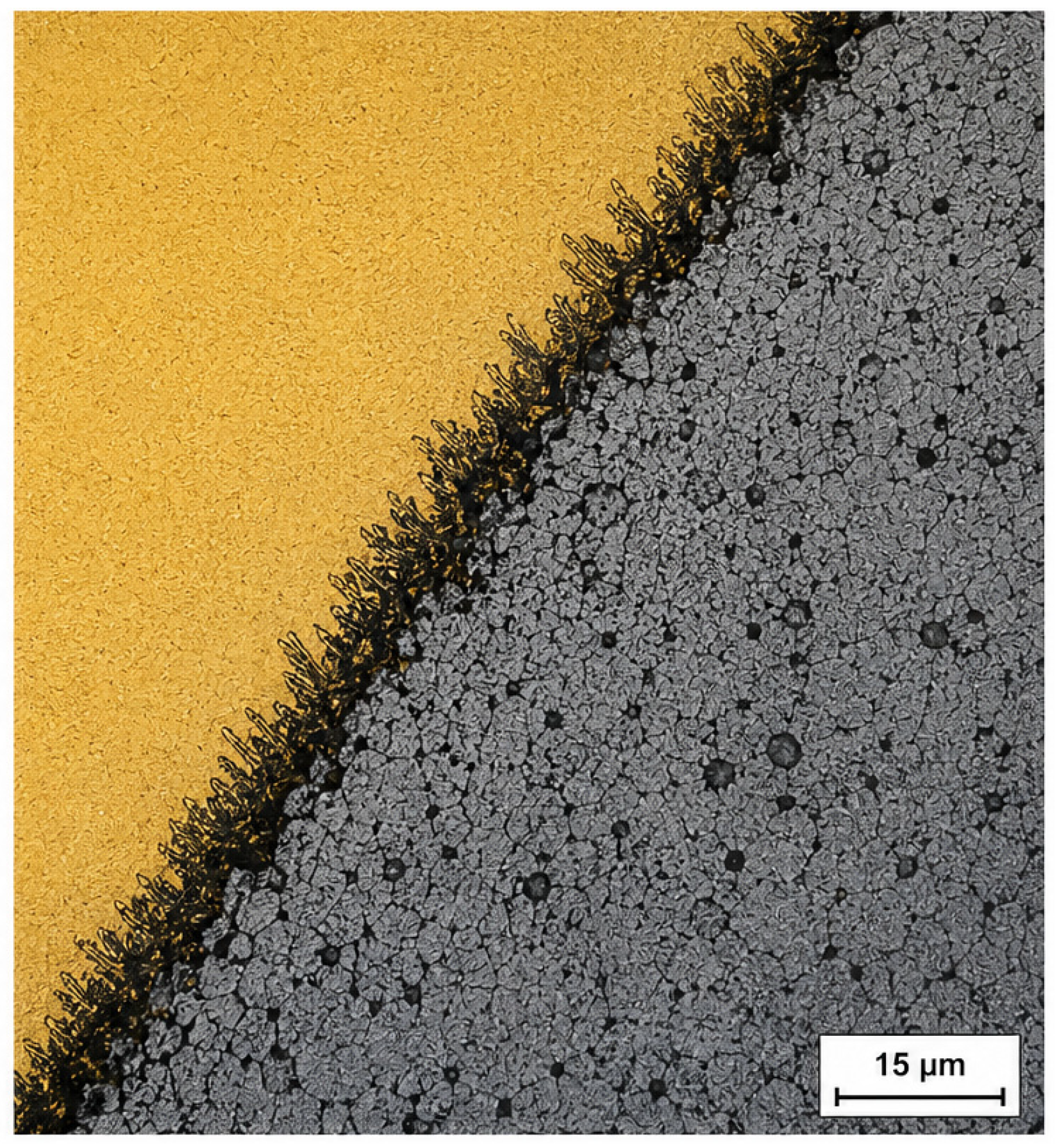
A detailed view of the transition zone is presented in Figure 20. The vicinity of the blowholes exhibits a non-uniform microstructure and local discontinuities at the interface between the braze metal and the steel substrate. The heat-affected zone extended through the entire sheet thickness and reached an average area of 2.71 mm2, which is substantially higher than the values measured for parameter sets A1 and B1. The observed morphology indicates that the increase in laser power was not accompanied by a sufficient increase in wire feed speed or robot travel speed. As a result, excessive heat accumulation occurred, leading to deterioration of joint quality and increased defect formation.
Figure 20.
Detail of the braze-to-sheet interface in specimen C2 showing localized microstructural heterogeneity associated with excessive thermal input.
3.2.6. Parameter Set D—P = 1000 W
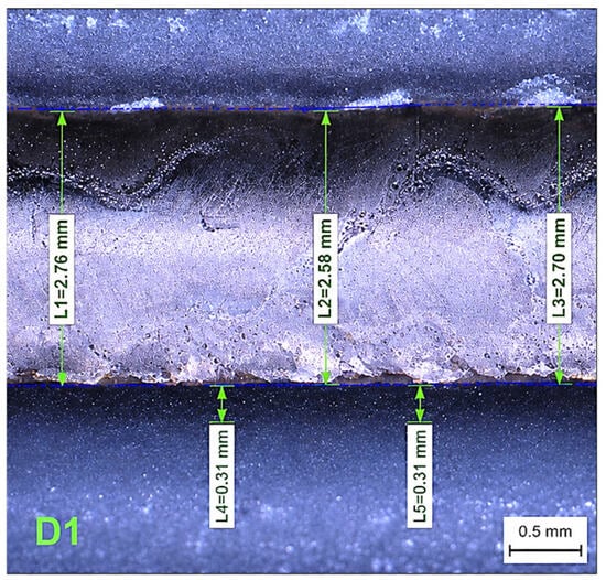
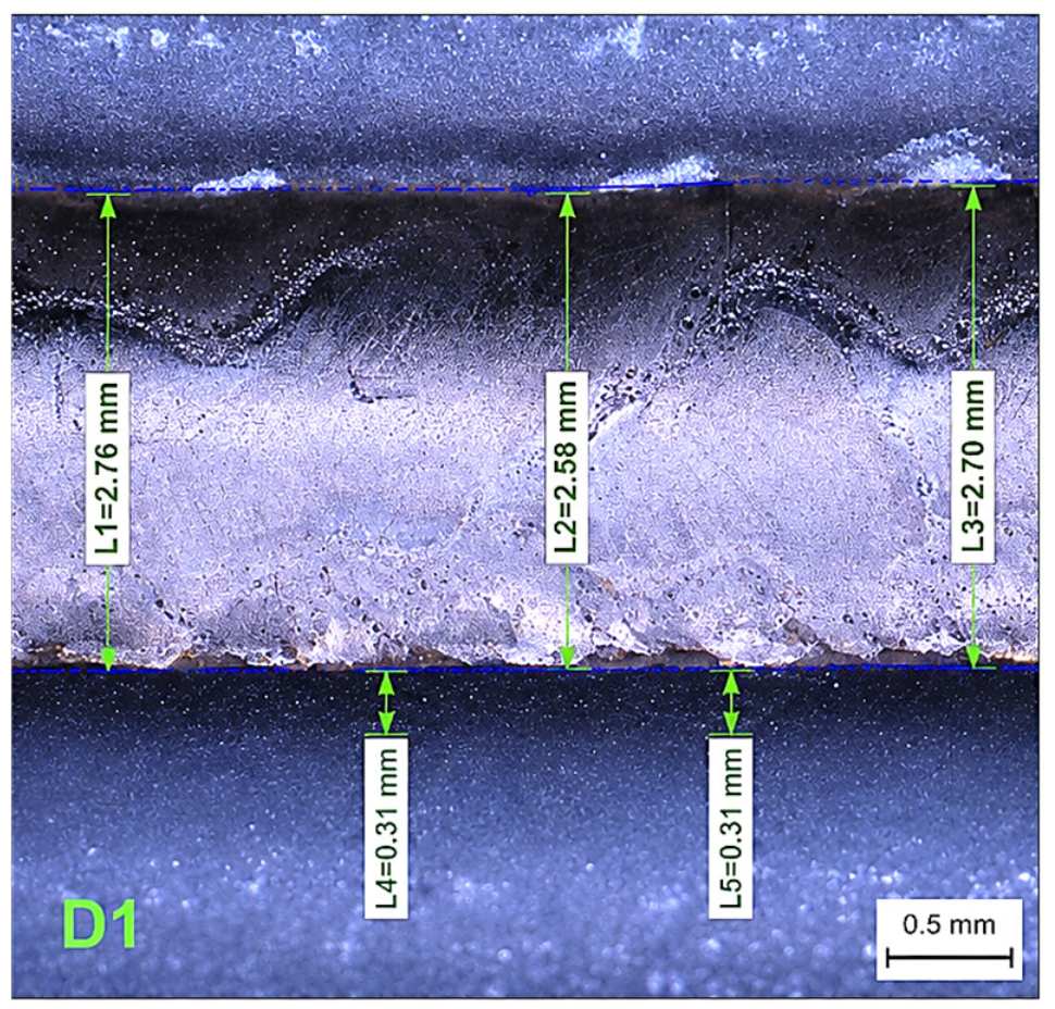
The cross-sectional morphology of specimen D1 is shown in Figure 21. The brazed joint exhibited a regular braze profile with a continuous braze-to-sheet interface and no visible macroscopic defects. The heat-affected zone remained relatively narrow, and characteristic segregation channels were observed within the braze metal.
Figure 21.
Cross-section of specimen D1 (P = 1000 W) exhibiting a regular braze profile and a narrow heat-affected zone.
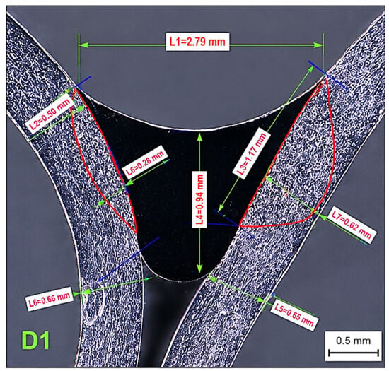
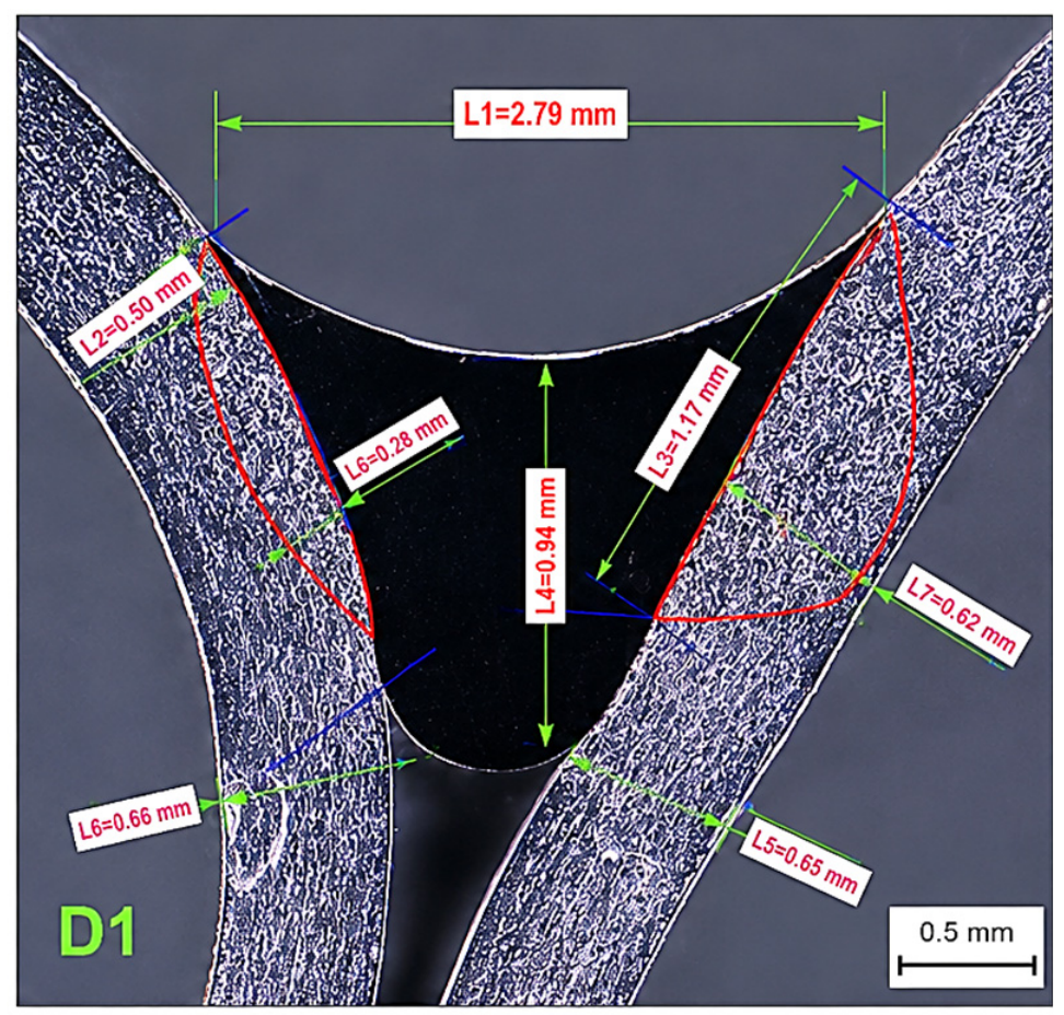
A detailed view of the transition zone is presented in Figure 22. Uniform wetting of both sheet edges and continuous bonding between the braze metal and steel substrate were observed. No significant porosity or local discontinuities were identified in the examined cross-section. The observed morphology indicates stable processing conditions despite the reduced laser power.
Figure 22.
Detail of the braze-to-sheet transition zone in specimen D1 showing continuous wetting and uniform interface formation.
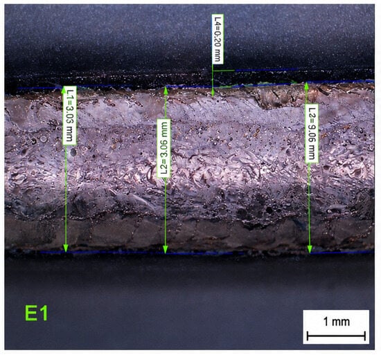
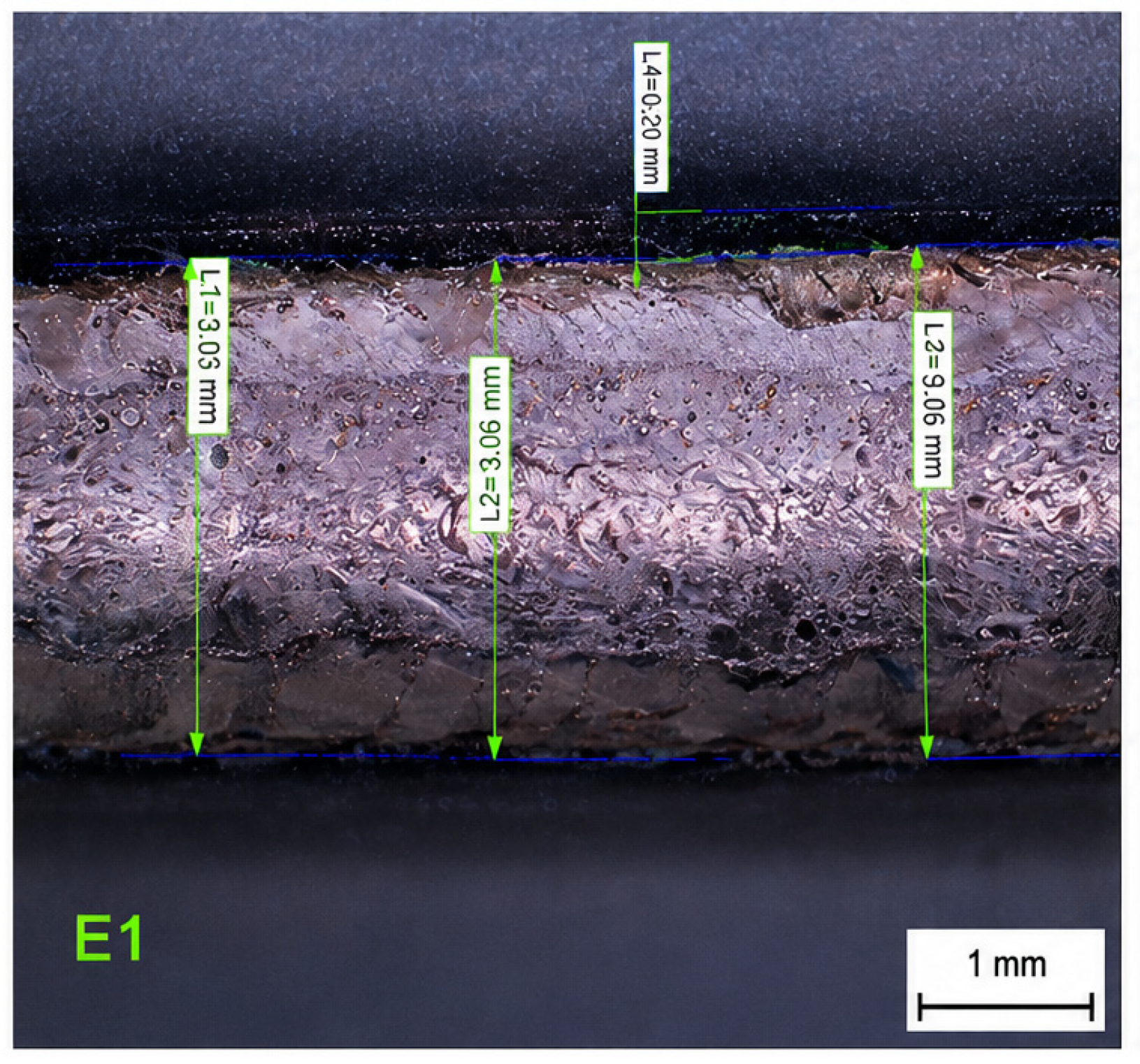
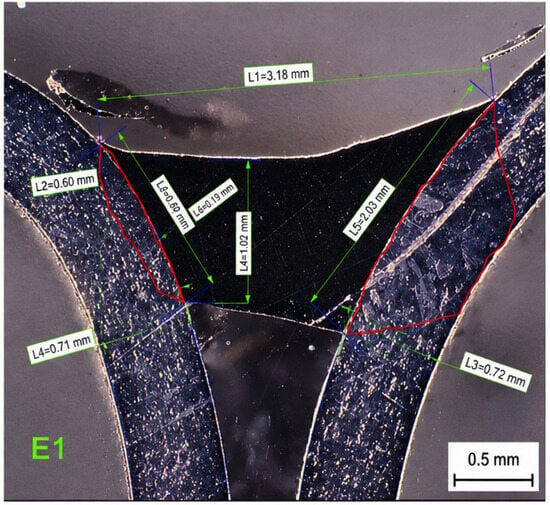
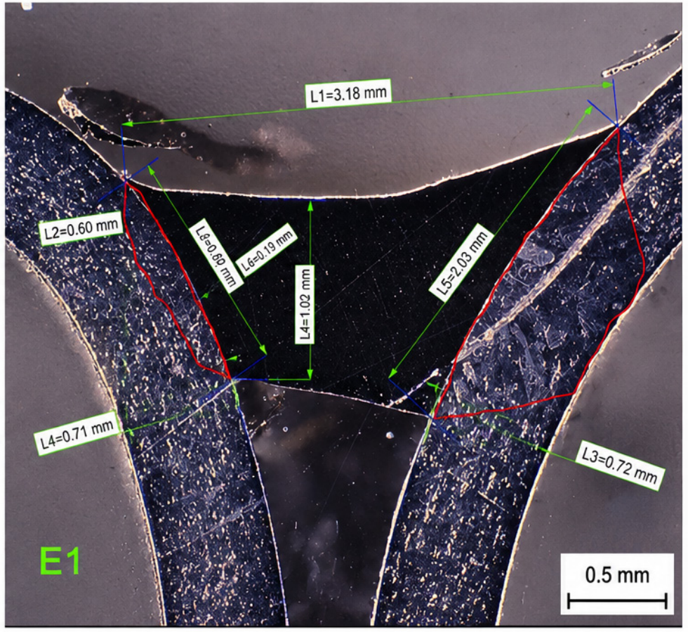
3.2.7. Parameter Set E—P = 1800 W
The cross-sectional morphology of specimen E1 is shown in Figure 23. In comparison with specimen D1, a pronounced increase in the extent of the heat-affected zone and a less uniform braze profile were observed. Local porosity and irregularities were present within the brazed region, indicating excessive thermal loading during the process.
Figure 23.
Cross-section of specimen E1 (P = 1800 W) exhibiting an irregular braze profile with increased porosity and extensive heat-affected zone development.
A detailed view of the braze-to-sheet transition zone is presented in Figure 24. The heat-affected zone extended deeper into the surrounding base material and exhibited larger dimensions than those observed in the lower-power parameter sets. Local interface irregularities and discontinuities were identified along the transition region, suggesting reduced process stability at the highest applied laser power.
Figure 24.
Detail of the braze-to-sheet transition zone in specimen E1 showing a widened heat-affected zone and local interface irregularities associated with excessive thermal input.
The comparison of specimens D1 and E1 demonstrates the effect of laser power on joint morphology and heat-affected zone development. While specimen D1 exhibited a regular joint geometry and limited HAZ growth, specimen E1 showed increased defect formation and more extensive thermal influence on the surrounding material.
3.3. Energy Balance and Quality Criterion
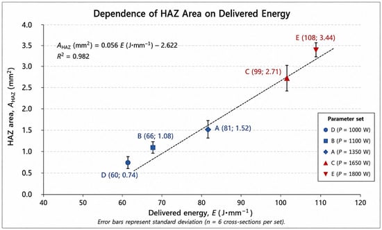
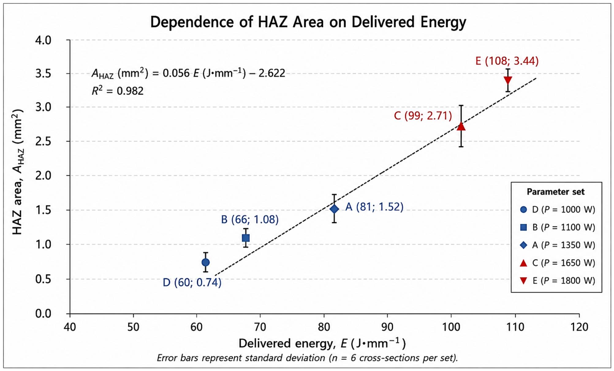
The dependence of the heat-affected zone (HAZ) area on delivered energy E [J·mm−1] was evaluated using quantitative metallographic measurements (n = 6 cross-sections per parameter set). From the viewpoint of laser material processing, delivered energy represents a key variable controlling local thermal response, heat accumulation, and the extent of thermally affected regions [32]. Linear regression of the experimental data obtained for parameter sets A–E resulted in the relationship HAZ [mm2] = 0.056E − 2.622 with a coefficient of determination R2 = 0.982, indicating a strong correlation between delivered energy and HAZ development.
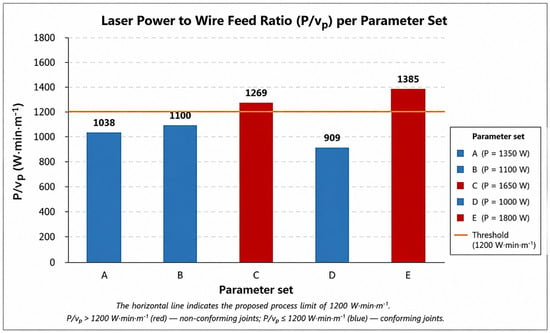
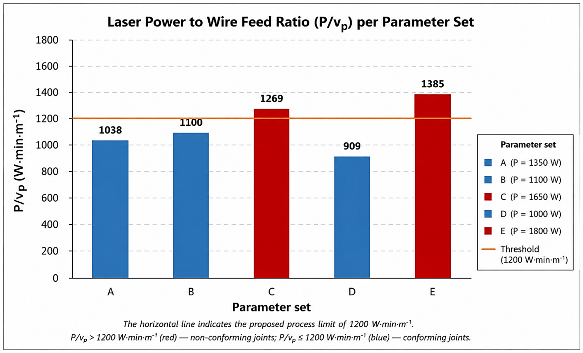
Figure 25 indicates an increasing trend in the HAZ area with increasing delivered energy. The largest HAZ values were measured for parameter sets C and E, which also exhibited the highest defect occurrence and degradation of the zinc coating. An exception was observed for parameter set B, where local differences in HAZ dimensions were detected despite identical nominal process parameters. This behaviour is attributed to local variations in joint gap geometry and fixture conditions during brazing. The results presented in Table 9 and Figure 26 suggest that joint quality is influenced more strongly by the balance between laser power and wire feed speed than by the absolute laser power alone. Within the investigated parameter range, acceptable joint quality was obtained through an appropriate balance between laser power and wire feed speed while maintaining a constant robot travel speed. Higher P/vp values were associated with increased heat-affected zone development and a higher occurrence of defects.
Figure 25.
Measured heat-affected zone (HAZ) area for parameter sets A–E. Error bars represent one standard deviation.
Table 9.
Process parameter balance for Sets A–E: laser power-to-wire-feed ratio (P/vp) and proportional imbalance Δmax relative to Set B reference.
Figure 26.
Laser power-to-wire-feed ratio (P/vp) for parameter sets A–E. The horizontal line indicates an observed transition range between acceptable and defective joints within the investigated parameter window.
The experimental results indicate that a laser power of 1100 W combined with a wire feed speed of 1.0 m·min−1 and a robot travel speed of 1.0 m·min−1 provides satisfactory brazing conditions for electrolytically galvanized DC06 sheets in the investigated thickness range (0.7–0.8 mm). The results further indicate that maintaining an appropriate balance between laser power, wire feed speed, and robot travel speed is more important than the absolute value of any individual process parameter. This interpretation is consistent with published findings showing that process window limits, heat transfer conditions, and energy distribution strongly affect joint formation and defect occurrence during laser brazing of zinc-coated automotive sheets [33,34,35].
4. Conclusions
This study investigated robotic laser brazing of electrolytically galvanized DC06 steel with CuSi3Mn1 filler wire under prototype production conditions. Based on the experimental results, the following conclusions can be drawn:
- (1)
- Relocation of the filler wire spool from a fixed external stand to the robot’s upper arm shortened the wire transport path and eliminated the need for a long protective liner. This modification reduced feeding resistance and improved the uniformity of braze deposition. The results showed that workstation configuration and wire feeding conditions can significantly influence the stability of robotic laser brazing under prototype production conditions.
- (2)
- Tensile testing of parameter sets A and B yielded tensile strength values between 293 and 314 MPa. In all cases, fracture occurred in the DC06 base material outside the brazed region, and no failure of the brazed seam was observed. The tests therefore confirmed the integrity of the brazed joints rather than providing a direct comparison of joint strength between parameter sets.
- (3)
- Metallographic analysis showed that parameter sets A, B, and D produced regular braze profiles with continuous braze-to-sheet interfaces and no critical metallurgical defects. In contrast, parameter sets C and E exhibited blowholes, convex braze geometry, zinc coating degradation, and significantly larger heat-affected zones as a consequence of excessive thermal input.
- (4)
- The measured HAZ area increased with delivered energy. Linear regression of the experimental data resulted in the relationship HAZ = 0.056E − 2.622 with R2 = 0.982, indicating a strong correlation between delivered energy and HAZ development within the investigated process window. The largest HAZ values were observed for parameter sets C and E, which also showed the highest occurrence of metallurgical defects.
- (5)
- Within the investigated parameter range, satisfactory joint quality was obtained through an appropriate balance between laser power and wire feed speed while maintaining a constant robot travel speed. Within the investigated parameter window, increased P/vp values were associated with greater HAZ development and a higher occurrence of defects.
- (6)
- The main contribution of this work is the combination of workstation optimization and experimentally verified process limits for robotic laser brazing under prototype production conditions, supporting the industrial relevance of laser brazing as a flexible joining technology for automotive body manufacturing [36,37]. The proposed wire feeding arrangement and parameter-setting criterion provide a practical basis for improving process stability when brazing thin electrolytically galvanized automotive body sheets.
Author Contributions
Concept, D.S., J.V. and J.B. (Janette Brezinová); methodology, J.B. (Janette Brezinová), J.V., D.S., J.B. (Jakub Brezina) and Š.N.; software, J.B. (Jakub Brezina) and Š.N.; validation, D.S., J.V., J.B. (Janette Brezinová) and J.B. (Jakub Brezina); formal analysis, J.V., J.B. (Janette Brezinová) and Š.N.; investigation, J.B. (Janette Brezinová) and D.S.; resources, D.S. and J.V.; data management, J.V., J.B. (Janette Brezinová) and D.S.; writing—preparation of the original draft, J.B. (Janette Brezinová), J.V. and D.S.; writing—revision and editing, J.B. (Janette Brezinová), J.B. (Jakub Brezina), J.V. and D.S.; visualization, J.V. and D.S.; supervision, J.V.; project management, J.B. (Janette Brezinová) and D.S.; fundraising, J.B. (Janette Brezinová). All authors have read and agreed to the published version of the manuscript.
Funding
This research was supported by the Visegrad Fund Fellowship No. 62610056, “Scientific Cooperation in Advanced Surface Engineering: Joint Research on PTA and Laser Cladding for Die-Casting Mold Renovation”; by the Slovak Research and Development Agency through the projects “Innovative Approaches to the Restoration of Functional Surfaces by Laser Surface Treatment” (APVV-20-0303) and “Integrity of Protective Multilayers under High-Temperature Exposure Conditions” (APVV-24-0381); by the VEGA Scientific Grant Agency through the project “Possibilities of Applying Laser Additive Technologies in the Restoration of Functional Surfaces” (1/0597/23); and by the Cultural and Educational Grant Agency KEGA through the projects “Hybrid Education of Students for the Current Needs of the Automotive Industry” (024TUKE-4/2025) and “Increasing the Competences of Graduates in the Automotive Production Study Program Using Virtual Reality Tools” (042TUKE-4/2026).
Data Availability Statement
The original contributions presented in this study are included in the article. Further inquiries can be directed to the corresponding author.
Conflicts of Interest
The authors declare no conflicts of interest.
References
- Hong, K.-M.; Shin, Y.C. Prospects of Laser Welding Technology in the Automotive Industry: A Review. J. Mater. Process. Technol. 2017, 245, 46–69. [Google Scholar] [CrossRef] [Scilit]
- Pouranvari, M.; Marashi, S.P.H. Critical Review of Automotive Steels Spot Welding: Process, Structure and Properties. Sci. Technol. Weld. Join. 2013, 18, 361–403. [Google Scholar] [CrossRef] [Scilit]
- Soomro, I.A.; Pedapati, S.R.; Awang, M. A Review of Advances in Resistance Spot Welding of Automotive Sheet Steels: Emerging Methods to Improve Joint Mechanical Performance. Int. J. Adv. Manuf. Technol. 2022, 118, 1335–1366. [Google Scholar] [CrossRef] [Scilit]
- Reimann, W.; Dobler, M.; Goede, M.; Schmidt, M.; Dilger, K. Three-Beam Laser Brazing of Zinc-Coated Steel. Int. J. Adv. Manuf. Technol. 2017, 90, 317–328. [Google Scholar] [CrossRef] [Scilit]
- Akbarian, S.; Sherepenko, O.; Sarafan, S.; Wanjara, P.; Gholipour, J.; Biro, E. Laser Brazing of Zinc-Coated Automotive Steels with a Focus on Improving Real-Time Quality Control of Vehicle Assembly. In Proceedings of the 62nd Conference of Metallurgists, COM 2023; Springer: Cham, Switzerland, 2023; pp. 411–413. [Google Scholar] [CrossRef] [Scilit]
- Reimann, W.; Pfriem, S.; Hammer, T.; Päthe, D.; Ungers, M.; Dilger, K. Influence of Different Zinc Coatings on Laser Brazing of Galvanized Steel. J. Mater. Process. Technol. 2017, 239, 75–82. [Google Scholar] [CrossRef] [Scilit]
- Mattulat, T.; Kügler, H.; Vollertsen, F. Investigations on the Occurrence of Different Wetting Regimes in Laser Brazing of Zinc-Coated Steel Sheets. Weld. World 2020, 64, 449–456. [Google Scholar] [CrossRef] [Scilit]
- Khan, M.S.; Cho, Y.H.; Zhang, S.; Goodwin, F.; Biro, E.; Zhou, Y.N. The Effect of Zinc Coating Type on the Morphology, Joint Geometry, and Mechanical Properties of Weld-Brazed Thin-Gauge Automotive Steel. Metall. Mater. Trans. A 2023, 54, 179–195. [Google Scholar] [CrossRef] [Scilit]
- Viňáš, J.; Brezinová, J.; Guzanová, A.; Maruschak, P.; Džupon, M. Properties Evaluation of the Welded Joints Made by Disk Laser. Materials 2021, 14, 2002. [Google Scholar] [CrossRef] [Scilit] [PubMed]
- Viňáš, J.; Brezinová, J.; Brezina, J.; Maruschak, P.O. Structural and Mechanical Features of Laser-Welded Joints of Zinc-Coated Advanced Steel Sheets. Mater. Sci. 2019, 55, 242–248. [Google Scholar] [CrossRef] [Scilit]
- Wang, G.; Huang, L.; Zhang, Y.; Cai, Y.; Chang, B. Optimization of Laser Brazing onto Galvanized Steel Based on Ensemble of Metamodels. J. Intell. Manuf. 2018, 29, 1417–1431. [Google Scholar] [CrossRef] [Scilit]
- Zhang, G.; Rong, Y.; Huang, Y.; Gu, Y.; Fan, C.; Shao, X. Integrated Optimization Model of Laser Brazing by Extreme Learning Machine and Genetic Algorithm. Int. J. Adv. Manuf. Technol. 2016, 87, 1633–1641. [Google Scholar] [CrossRef] [Scilit]
- Ye, Y.; Li, P.; Zhang, H.; Liu, H. Morphology, Microstructure and Mechanical Property of Laser Brazing of Galvanized Steel in a Flange Butted Configuration. Opt. Laser Technol. 2024, 179, 111368. [Google Scholar] [CrossRef] [Scilit]
- Zhang, Z.; Zhao, Y.; Wu, S.; Chen, S.; Li, Y.; Zhang, J. Optimization of Butt Welding of Zinc-Coated Thin Sheets with Oscillating Fiber Laser Beams: Weld Formation, Microstructure, and Mechanical Properties. Weld. World 2021, 65, 1711–1723. [Google Scholar] [CrossRef] [Scilit]
- He, B.; Liu, J.; Liu, Z.; Chen, X.; Cao, Z. Detection of Wire Feeding Speed and Its Influence on Rotating Arc Welding Quality. Int. J. Adv. Manuf. Technol. 2023, 127, 1293–1305. [Google Scholar] [CrossRef] [Scilit]
- Zdravecká, E.; Slota, J. Mechanical and Microstructural Investigations of the Laser Welding of Different Zinc-Coated Steels. Metals 2019, 9, 91. [Google Scholar] [CrossRef] [Scilit]
- Koltsov, A.; Bailly, N.; Cretteur, L. Wetting and Laser Brazing of Zn-Coated Steel Products by CuSi Filler Metal. J. Mater. Sci. 2010, 45, 2118–2125. [Google Scholar] [CrossRef] [Scilit]
- Li, H.; Ye, Y.; Liu, H. Joint Formation Mechanism and Mechanical Properties of Laser Brazed Zn-Coated Steel Under Different Defocusing Conditions. J. Mater. Res. Technol. 2024, 31, 3267–3280. [Google Scholar] [CrossRef] [Scilit]
- Sharma, A.; Lee, S.J.; Choi, D.Y.; Jung, J.P. Effect of Brazing Current and Speed on the Bead Characteristics, Microstructure, and Mechanical Properties of Arc Brazed Galvanized Steel Sheets. J. Mater. Process. Technol. 2017, 249, 212–220. [Google Scholar] [CrossRef] [Scilit]
- Guzanová, A.; Brezinová, J.; Draganovská, D.; Maruschak, P.; Vojtko, M.; Viňáš, J.; Džupon, M. Experimental Study of Steel–Aluminum Joints Made by RSW with Insert Element and Adhesive Bonding. Materials 2023, 16, 864. [Google Scholar] [CrossRef] [Scilit] [PubMed]
- Rong, Y.; Zhang, Z.; Zhang, G.; Yue, C.; Gu, Y.; Huang, Y.; Wang, C.; Shao, X. Parameters Optimization of Laser Brazing in Crimping Butt Using Taguchi and BPNN-GA. Opt. Lasers Eng. 2015, 67, 94–104. [Google Scholar] [CrossRef] [Scilit]
- Volpp, J.; Vollertsen, F. Impact of Multi-Focus Beam Shaping on the Process Stability during Laser Brazing. Opt. Laser Technol. 2019, 112, 278–283. [Google Scholar] [CrossRef] [Scilit]
- Zhang, Y.; Wang, G.; Chang, B. Energy Input Effects on Laser Brazing Quality of Galvanized Steel. Opt. Laser Technol. 2020, 132, 106494. [Google Scholar] [CrossRef] [Scilit]
- EN ISO 24373:2018; Welding Consumables—Solid Wires and Rods for Fusion Welding of Copper and Copper Alloys—Classification. International Organization for Standardization (ISO): Geneva, Switzerland, 2018.
- Vander Voort, G.F. Metallography: Principles and Practice; McGraw–Hill: New York, NY, USA, 1984. [Google Scholar]
- Nikitin, A.; Schleuss, L.; Ossenbrink, R.; Michailov, V. Corrosion Behavior of Brazed Zinc-Coated Structured Sheet Metal. Int. J. Corros. 2017, 2017, 4768505. [Google Scholar] [CrossRef] [Scilit]
- Wang, C.; Cui, L.; Mi, G.; Jiang, P.; Shao, X.; Rong, Y. The influence of heat input on microstructure and mechanical properties for dissimilar welding of galvanized steel to 6061 aluminum alloy in a zero-gap lap joint configuration. J. Alloys Compd. 2017, 726, 556–566. [Google Scholar] [CrossRef] [Scilit]
- Schubert, E.; Klassen, M.; Zerner, I.; Walz, C.; Sepold, G. Light-weight structures produced by laser beam joining for future applications in automobile and aerospace industry. J. Mater. Process. Technol. 2001, 115, 2–8. [Google Scholar] [CrossRef] [Scilit]
- Katayama, S. Laser Welding: Principles and Applications. In Handbook of Laser Welding Technologies; Woodhead Publishing: Cambridge, UK, 2013; pp. 3–38. [Google Scholar]
- Kai, M.; Zhishui, Y.; Peilei, Z.; Yunlong, L.; Hua, Y.; Chonggui, L.; Xiaopeng, L. Influence of wire feeding speed on laser brazing zinc-coated steel with Cu-based filler metal. Int. J. Adv. Manuf. Technol. 2015, 76, 1333–1342. [Google Scholar] [CrossRef] [Scilit]
- Li, S.; Liu, H.; Zhang, H. Effect of Different Process Parameters on Three-Spot Laser Brazing of Galvanized Steel. J. Mater. Eng. Perform. 2024, 33, 5727–5734. [Google Scholar] [CrossRef] [Scilit]
- Steen, W.M.; Mazumder, J. Laser Material Processing, 4th ed.; Springer: London, UK, 2010. [Google Scholar]
- Gatzen, M.; Radel, T.; Thomy, C.; Vollertsen, F. Wetting and solidification characteristics of aluminium on zinc coated steel in laser welding and brazing. J. Mater. Process. Technol. 2016, 238, 352–360. [Google Scholar] [CrossRef] [Scilit]
- Li, S.; Yu, Z.; Zhang, P.; Li, X.; Qiu, D.; Liu, X. Numerical Simulation and Parameters Optimization of Laser Brazing of Galvanized Steel. ISIJ Int. 2016, 56, 637–646. [Google Scholar] [CrossRef] [Scilit]
- Heuberger, E.; Schmid, D.; Weberpals, J.-P.; Tenner, F.; Schmidt, M. Influence of the brazing speed on the seam characteristics in laser beam brazing of zinc coated steel. J. Laser Appl. 2019, 31, 022407. [Google Scholar] [CrossRef] [Scilit]
- Heitmanek, M.; Dobler, M.; Graudenz, M.; Perret, W.; Göbel, G.; Schmidt, M.; Beyer, E. Laser brazing with beam scanning: Experimental and simulative analysis. Phys. Procedia 2014, 56, 689–698. [Google Scholar] [CrossRef] [Scilit]
- Gatzen, M.; Radel, T.; Thomy, C.; Vollertsen, F. The role of zinc layer during wetting of aluminium on zinc-coated steel in laser brazing and welding. Phys. Procedia 2014, 56, 730–739. [Google Scholar] [CrossRef] [Scilit]

Disclaimer/Publisher’s Note: The statements, opinions and data contained in all publications are solely those of the individual author(s) and contributor(s) and not of MDPI and/or the editor(s). MDPI and/or the editor(s) disclaim responsibility for any injury to people or property resulting from any ideas, methods, instructions or products referred to in the content. |
© 2026 by the authors. Licensee MDPI, Basel, Switzerland. This article is an open access article distributed under the terms and conditions of the Creative Commons Attribution (CC BY) license.