Article

Ball-End Copy-Milling of Slender Aluminium 5083 Workpieces Under Bending Loads

by
Álvaro Sáinz de la Maza García
*,
Gonzalo Martínez de Pissón Caruncho
and
Luis Norberto López de Lacalle Marcaide
Aeronautics Advanced Manufacturing Centre (CFAA), University of the Basque Country (UPV/EHU), 48170 Zamudio, Spain
*
Author to whom correspondence should be addressed.
J. Manuf. Mater. Process. 2026, 10(5), 156; https://doi.org/10.3390/jmmp10050156
Submission received: 30 March 2026 / Revised: 24 April 2026 / Accepted: 28 April 2026 / Published: 29 April 2026
(This article belongs to the Special Issue Next-Generation Machine Tools and Machining Technology)

Abstract

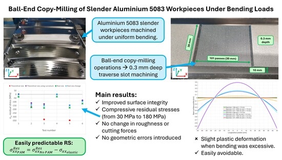
Ball-end copy-milling is widely used for finishing complex components, yet its influence on surface integrity is generally overlooked and remains insufficiently addressed. Milling often generates tensile residual stresses at the machined surface, which are detrimental to fatigue performance and commonly require costly postprocessing, particularly in fatigue-critical parts such as turbine blades. In this context, the present study evaluates the capability of Prestress-Assisted Machining under uniform bending loads to improve the surface integrity of ball-end copy-milled Aluminium 5083 workpieces. Experimental tests were conducted on slender specimens with different thicknesses and curvature radii while maintaining constant cutting conditions. After machining and unclamping, surface residual stresses were measured by X-ray diffraction, and the effects of prestressing on geometry, cutting forces and surface roughness were also assessed. The results demonstrate that this method markedly increases compressive residual stresses in the prestressing direction, from approximately 30 MPa to about 180 MPa, and that this variation can be accurately described by subtracting the elastic prestressing stress from the residual stresses obtained without external loads applied. Moreover, no relevant adverse effects were observed in cutting forces or roughness, and corrected toolpaths allowed a uniform slot depth. These findings identify bending-based Prestress-Assisted Machining as an effective and predictable strategy for improving surface integrity in ball-end copy-milling and extend its applicability beyond previously reported pocket and slot milling operations.

Graphical Abstract

1. Introduction

Critical mechanical components are commonly subjected to cyclic service loads, which often trigger crack initiation and growth. Fatigue cracks tend to start near surface defects, and their growth speed and chances of appearing are increased by tensile residual stresses, while compressive ones slow down the process and are generally desirable in safety-critical parts. This is especially relevant in sectors such as aerospace and power generation, where high structural reliability, dimensional stability and fatigue resistance are required simultaneously. Combining the importance of surface and the effect of residual stresses, when manufacturing these components, it is crucial to ensure that final surface residual stresses are compressive [1]. Recent reviews also highlight that, beyond fatigue, residual stresses play a major role in the distortion, dimensional accuracy and subsequent manufacturing behaviour of aluminium structural components, particularly in thin-walled parts [2].
However, many critical components, for example in the aerospace sector, also present complex free-form geometries, commonly finished by milling operations. Among them, ball-end copy-milling strategies are widely used for the finishing of blades, impellers and other sculptured surfaces. These operations may introduce both compressive (if mechanical effect is larger than the thermal one) or tensile residual stresses (when thermal effects are more prominent) near the fresh machined surface [3]. Unfortunately, the introduction of tensile surface residual stresses is the most common result. In milling operations, the most usual residual stress profile is characterized by high-magnitude tensile residual stresses in a very thin layer below the surface, followed by a thicker layer of compressive residual stresses at larger depth below the surface, until it is stabilized much deeper [4,5]. Recent studies focused on ball-end milling show that tool orientation and cutting strategy can significantly modify the resulting surface integrity, including roughness, surface damage and residual stress state [6,7].
Even though extensive research was conducted to predict machining-induced residual stresses [8,9,10], controlling them by modifying conventional cutting parameters is still not a reality. Usually, research is more focused on the compensation of residual stress-induced deformation than on the control of residual stresses themselves, such as what M. Aurrekoetxea et al. [11] or D. Weber et al. [12] proposed. Consequently, after the machining operation is completed, most critical components are subjected to additional postprocessing steps to remove undesired tensile surface residual stresses, and in some cases, even introduce compressive ones instead. These postprocessing operations may consist of mechanical (deep rolling, shot peening, etc.) [13] or thermal (annealing, normalising) [14] surface treatments. Although effective, these additional steps increase costs and reduce manufacturing efficiency.
In this context, to avoid additional postprocessing, recently, an alternative method was developed: the use of Prestress-Assisted Machining (PAM), consisting of machining a workpiece while it is subjected to externally applied loads. When the machined component is unclamped, prestressing loads are removed, and workpiece elastic recovery introduces compressive surface residual stresses. This method was first proposed by Á. Sáinz de la Maza García et al. [15] to machine thin slender components under pure tensile loads. After that, an alternative solution consisting of applying uniform bending loads for pocket milling operations on thicker components was proposed [16].
However, despite these advances, the application of PAM to ball-end copy-milling operations has not been investigated yet. This is an important gap, since many high-value-added components originally motivating the development of PAM, such as turbine blades, are commonly finished by ball-end copy-milling rather than by simpler planar milling operations. Therefore, the novelty of the present study does not lie in proposing a new prestressing model or a new fixture design, but in determining whether the framework previously validated for pocket milling under bending loads can be extended to ball-end copy-milling. In particular, this work addresses two main questions: whether previously proposed equations remain valid in ball-end copy-milling operations, and whether the residual-stress benefits previously observed in pocket milling can also be achieved in this case without introducing adverse effects on geometry, cutting forces or surface roughness.
After establishing the theoretical basis and experimental procedure, this work examines the obtained results and their impact in industrially relevant machining operations.

2. Theoretical Basis

A simple model to better understand how PAM works was proposed in previous research [15]. It considers the workpiece as a two-layered component; the surface layer is affected by the machining operation (both thermally and mechanically), while the bulk material remains unaffected. When PAM is applied, during the prestressing stage, the material is subjected to externally introduced stresses, which can be of any kind. For this work, bending loads are considered, so theoretical explanations will be supported in this kind of load, considering that the machining operation is shallow in the external surface of the curve. In the case of bending, stress profile varies linearly from tensile to compressive between both external surfaces, but in this work, as the depth of cut is smaller than half the thickness, cutting is performed in the volume of tensile stress.
During the machining operation, stresses in the bulk material are nearly constant, while the machined surface suffers significant changes due to thermal and mechanical effects, which leads to a residual stress profile that depends on the cutting conditions. In previous works, it was seen that these residual stresses are not significantly affected by the external loads, meaning that for the near-surface layer, machining-induced residual stresses may be considered equal to those obtained by the same operation without externally applied loads. Once the machining operation is finished, during the unclamping stage, external loads are removed and the elastic recovery of workpiece material forces a compression in the fresh machined surface. Consequently, final residual stress state is the combination of the machining-induced residual stresses, and the effect of the elastic recovery. It can be somehow compared to pretensioned concrete, where tensioned tendons are introduced inside concrete components during the casting stage, and once the concrete is cured, tendons are freed, introducing compressive loads in the concrete due to their elastic recovery.
In previous work [16], it was verified that, at least for bending loads, surface residual stresses resulting from applying PAM ( σ x x P A M R e s ) can be calculated as the surface residual stresses obtained without prestressing ( σ x x N o P A M R e s ), minus the elastic stress introduced by prestressing loads ( σ x x e l a s t i c ), as exposed in Equation (1). Hence, tensile prestressing generally yields compressive surface residual stresses, whereas compressive prestressing tends to produce tensile ones. It must be noted that if plastic deformation appears during prestressing, only the elastic component leads to a variation in surface residual stresses.
σ x x P A M R e s = σ x x N o P A M R e s σ x x e l a s t i c
It must be noted that Equation (1) should be valid for a broad range of machining operations as it correlates the residual stress state of a component machined under externally applied loads to the result of not applying any external load. Therefore, Equation (1) bases its predictions on the measurement of residual stresses in non-prestressed machining.
In this work, all tests were performed using rather thin and slender workpieces bent in their longitudinal direction. In this framework, near the external surface, introduced stresses in Z direction (normal to the surface) are zero (plane stress case), whereas in X direction (longitudinal direction) PAM is governed by Equation (1), and in the direction perpendicular to the bending plane (Y direction), applied bending does not directly affect stresses, and as a consequence, residual stresses in Y direction remain almost unmodified by the prestressing. Bearing this in mind, using the proposed method, the introduction of compressive residual stresses was only expected in one direction. In case compressive residual stresses are to be achieved in any direction in the fresh machined surface, bending should be applied in all directions, that is, introducing a spherical bending instead of a cylindrical one.
When bending loads are applied, if E is the elastic modulus, ε x x is the strain, and R is the bending radius, the stress σ x x introduced at a distance d to the neutral fibre (negative towards the centre of curvature) may be calculated using Equation (2). This Equation shows that introduced stress is inversely proportional to the bending radius and, as a consequence, to achieve a uniform stress distribution in the workpiece (at a certain depth below the surface), keeping a uniform bending radius is needed. Therefore, instead of using a simpler three-point-bending, the bending is performed deforming the workpiece against a cylindrical surface of known curvature radius.
σ x x = E ε x x = E d R

3. Experimental Testing

Theoretical considerations and previous research works indicate that applying prestressing loads during milling operations may have significant benefits, mainly in the fresh machined surface integrity. However, to validate if applying bending loads during ball-end copy-milling operations may be useful for critical components, some experimental tests were needed. The key parameters of these tests are summarized hereafter.
To obtain directly comparable results with previous PAM studies under bending loads, the same general methodology proposed by Á. Sáinz de la Maza García et al. [16] was followed, by using various workpiece thicknesses and bending radii while keeping cutting conditions equal in all tests. This was chosen so that any differences observed could be attributed to the change in machining operation, namely the transition from pocket milling to ball-end copy-milling, rather than to modifications in material, fixture design or testing procedure.
Similarly, as done in that research, some of the specimens were bent over their yield stress to validate that the simple prediction of residual stresses as the ones without applying PAM minus the introduced elastic stresses is adequate also for copy-milling operations even when plastic deformations are induced. Therefore, workpiece thickness and curvature radius for each testing condition are summarized in Table 1. For test numbers 1, 2, 3 and 6, each test was repeated three times, while tests 4 and 5 were performed twice. Test 4 effectively represented the same situation (in terms of surface integrity) as test case 1, while test case 5 had a non-ideal bending radius, as will be described later (Figure 2). Therefore, it was considered that repeating these tests for a third time did not give any scientific benefit. As results were very similar between repetitions (<5% differences), in this article, the average results are shown.
To introduce these prestressing bending loads, the same method and fixture design proposed by Á. Sáinz de la Maza García et al. [16] were used. The fixture includes six clamping surfaces of different radii (flat, 4000, 2000, 1000, 500 and 300 mm; the 300 mm surface was not used in this work). The flat surface served for reference testing as a comparison to non-prestressed machining. The key advantage is that, for a given thickness and curvature radius, the applied stress is uniform along the machining length and repeatable without direct stress measurement. The system is also insensitive to bolt tightening torque as the workpiece remains in full contact with the curved surface. The fixture was installed on top of a Kistler 9255B (Kistler Instrumente AG, Winterthur, Switzerland) dynamometric table to measure cutting forces. Testpieces were clamped to the fixture by means of bolts and thick washers, as shown in Figure 1.
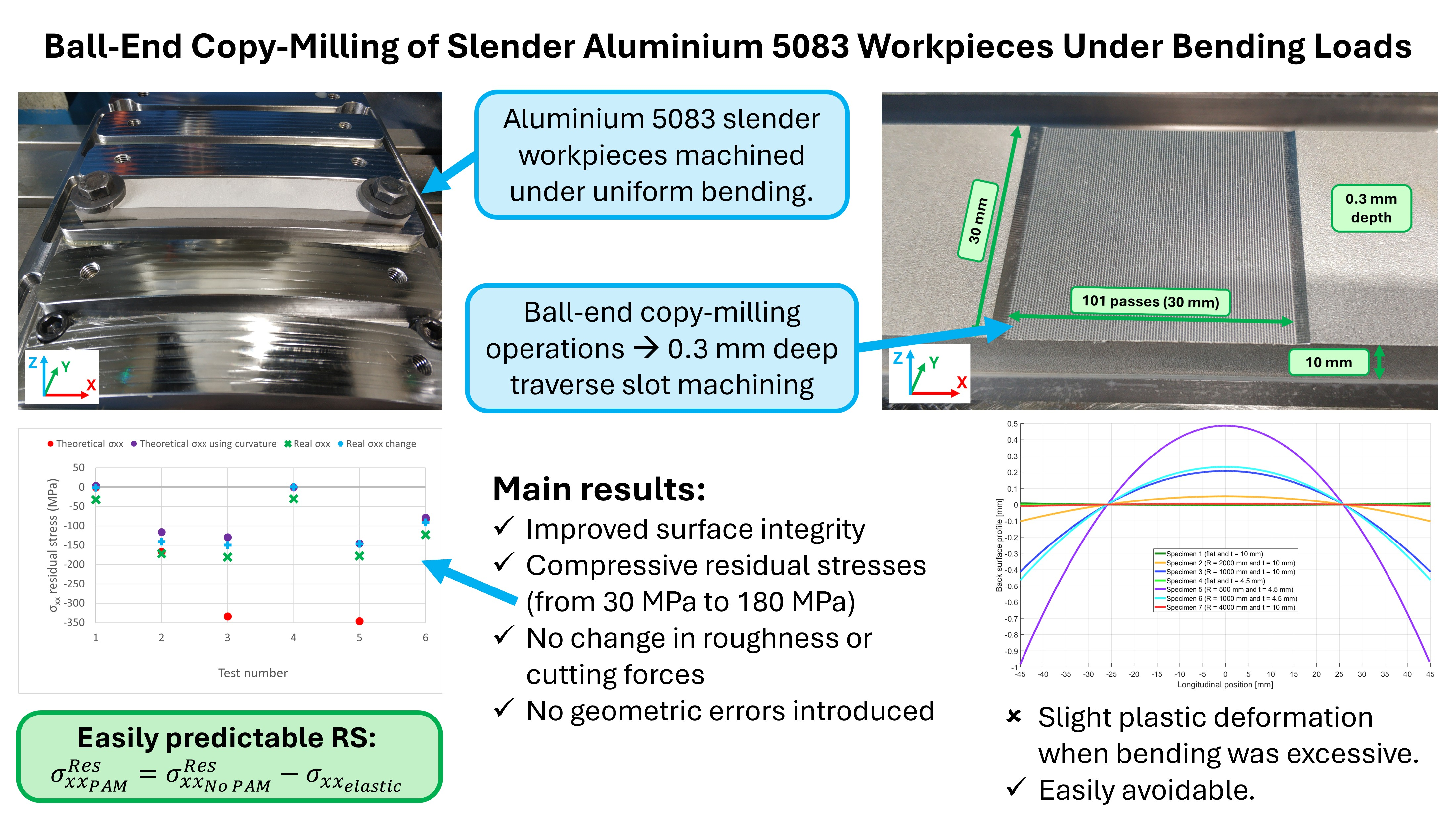
It must be noted that even though in test 5 the curvature used was 500 mm, due to the clamping system and the low thickness of the workpiece, it was seen that the real bending radius was reduced in both repetitions to about 410 mm, which was taken into account in residual stress calculation. Figure 2 shows how the horizontal component F x of the clamping force F tends to overbend the specimen due to the friction with the testpiece surface, which leads to the situation shown in Figure 2. There was a concern that the same phenomenon might also have occurred in other tests. Consequently, all workpieces were measured using the machine touch probe and their geometry was compared to an ideal cylindrical shape of the expected radius (fixture curvature radius plus workpiece thickness). Except for testcase 5, measured curvature radii were very close to the expected values, indicating that all other specimens were machined in proper contact with the fixture, as intended. This suggests that, for industrial implementation, the prestressing system may require further optimization to ensure a robust and repeatable transfer of the desired curvature to the workpiece. Although this issue was only observed in the most demanding test case, alternative clamping or loading solutions could be considered to improve process reliability under production conditions.
In all cases, a 0.3 mm deep slot was milled by 101 parallel copy-milling passes in perpendicular direction to the applied stress, and using a radial depth of cut of 0.3 mm, leading to a 30 mm flat slot floor surface. The main machining conditions used for testing are summarized in Table 2. The final geometry of the machined area is shown in Figure 3. These tests were carried out in a high-speed Kondia HS1000 (Kondia, Elgoibar, Spain) milling machine in aluminium Al 5083 testpieces. For the tests performed under bending loads, the machining paths were not coplanar to achieve a uniform depth of cut. Instead, a simple MATLAB (R2024a version) program was used to generate the corrected trajectories, directly in Heidenhain programming language. Since the operation consisted of parallel copy-milling passes, the compensation was straightforward: the successive passes were defined as the generatrices of a cylinder coaxial with the curved clamping surface. The radius of the paths followed by different passes, considering the centre of the spherical tool-tip as a reference, was calculated as the fixture curvature radius plus the workpiece thickness plus the radius of the end-mill minus the depth of cut. This way, once the workpiece was unclamped, the resulting slot depth remained constant, no matter the curvature radius used.
Cutting forces were measured during machining by means of the Kistler 9255B dynamometric table on which the prestressing fixture was mounted, using a 16.4 kHz acquisition frequency. For surface-quality assessment, roughness measurements were performed after machining and unclamping on the milled slot floor using an Alicona Infinite Focus G5 (Alicona Imaging GmbH, Raaba, Austria) focus variation microscope (optical measurement), obtaining the Ra and Rz parameters in the same area for all testpieces and according to ISO 4288 standard [17], using a cut-off length of 800 μ m and averaging roughness measurements of 1000 profiles (all of them in the direction of highest roughness).
To study machining-induced surface residual stresses, after completing the milling operation and unclamping the workpiece, surface residual stresses were measured using the X-Ray diffraction (XRD) method. We chose this method over other alternatives, such as ASTM hole-drilling [18] even though it is limited to surface measurements, because in previous research it was seen that results were more repeatable and gave smaller averaged residual stress values in a thinner surface layer. Some authors, such as X. Li et al. [19], also support the selection of XRD for surface residual stress measurements over hole-drilling method. XRD measurements were performed in the centre of the milled surface, keeping the same measurement zone for all testpieces. The residual stress measurement uncertainty was well below ±5 MPa for all workpieces. The main parameters used for these measurements are summarized in Table 3.

4. Results and Discussion

When applying PAM, two main benefits could be expected. (1) In thin components with very low stiffness, PAM tends to increase it, reducing deformations and vibrations. (2) Using PAM allows us to easily control residual stresses and avoid tensile ones. In this work, bending was performed against a fixture with contact in the whole length, so the effect of the stress-stiffening phenomenon is expected to be negligible. Consequently, the goal is to verify if using PAM with the specified conditions leads to controllable residual stresses without negatively affecting any other parameter. In this sense, the effect of bending loads was analysed in terms of surface residual stresses, geometry errors, cutting forces and roughness.

4.1. Residual Stresses

When studying how PAM affects residual stresses, considering that bending generates tensile stresses in the outer surface and that performed machining operations are shallow, the introduction of compressive surface residual stresses was expected. Furthermore, in this research, the possibility of predicting final residual stresses was also analysed. It must be clarified that thanks to the thermal treatment of the material used, initial residual stresses were virtually zero.
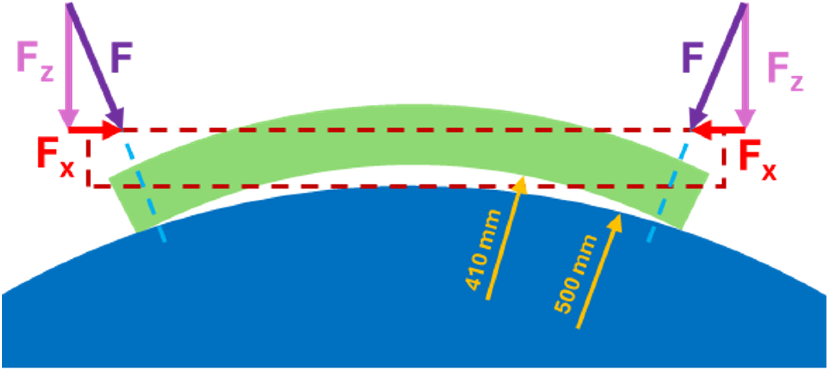
Measured surface residual stresses in each case of study are summarized in Figure 4 as green crosses (residual stress measurement uncertainty is lower than ±5 MPa in all testpieces). However, the goal of measuring residual stresses was to compare the use of PAM with non-prestressed machining. Therefore, instead of working with measured values (green crosses), blue plus signs in Figure 4 were calculated by subtracting the average value of tests 1 and 4, without prestressing. These values are more interesting, as they lead to the change in residual stresses induced by prestressing compared to the non-prestressed situation. From these results, it is clear that when bending was applied, surface residual stresses became much more compressive.
Using experimental results is useful at a laboratory level to determine that PAM behaves as expected, but for industrial use, being able to predict the effect of using PAM on residual stresses is needed. However, predicting residual stress is still a complex task; therefore, in this research, instead of predicting residual stresses, determining the difference of these when using PAM compared to the non-prestressed machining was pursued.
Consequently, the main objective was to determine if Equation (1), proposed for pocket milling operations, also provides an adequate prediction of residual stresses in ball-end copy-milling operations under uniform bending loads. As predicted results should be compared to blue plus signs (effect of PAM compared to the base value), for calculation, the residual stress result of not applying PAM can be considered zero, leading to a more intuitive comparison. The values resulting from Equation (1) without considering the effect of plastic deformations are plotted as red dots in Figure 4.
However, in that calculation, it was considered that all the bending only exerted elastic deformations; in other words, the yield stress was not taken into account. As exposed in Section 4.2, some tests (mainly test cases 3 and 5 and, to a lesser extent, test 2) suffered plastic deformations, so predicted values must be adapted to consider only elastic deformations as written in Equation (1). Instead of analytically calculating plastic deformation, to reduce any error introduced, for example, by a deviation in real yield stress value, this was achieved by measuring final workpiece curvature, and based on it, real plastic deformation was calculated. These corrected values are plotted in Figure 4 as purple dots. As expected, measured surface residual stresses (green crosses) are limited to approximately the yield stress of the material (about 180 MPa), leading to a greater difference of red and purple dots in tests 3 and 5, where yield stress was surpassed by a larger amount.
In Figure 4, purple dots (predictions considering plastic deformations) should be compared to blue plus signs (measured effect of using PAM). It can be seen that predictions fit almost perfectly with experimental test results, meaning that the effect of applying PAM can be effectively predicted by subtracting the elastic stress introduced in the material on the fresh machined surface to the residual stresses obtained without any prestressing load. This approach was validated for different study cases, with various operations and cutting parameters, which likely means that the proposed equation is satisfied in more complex operations. It must be noted that the small discrepancies between purple dots and blue plus signs are due to the effect of having compressive residual stresses just in one of the external surfaces, which tends to slightly bend the specimens.
Having such a simple model to predict how PAM affects surface integrity makes this method an industrially interesting approach to ensure controlled surface residual stresses in fresh machined surfaces, which allows improving the fatigue behaviour of final components. As the effect on residual stresses can be easily predicted, it is possible to determine the needed elastic stress (and consequently, the required loads) to achieve the desired residual stress distribution.
A secondary observation regarding residual stresses was that, in the direction perpendicular to the bending plane (Y direction), measured values became slightly more compressive than without prestressing, changing from about −6 MPa to approximately −21 MPa. Although this variation is very small compared with the main effect observed in the X direction, it is larger than the nominal XRD measurement uncertainty (±5 MPa), which suggests that it may correspond to a minor, but real, secondary effect. Since the simplified theoretical model assumes ideal cylindrical bending and predicts no direct contribution in the Y direction, this result is not interpreted as a contradiction of the model, but rather as a higher-order effect not captured by it. Possible causes include transverse elastic deformation associated with the longitudinal stress state, slight deviations from the ideal uniaxial bending condition due to clamping and real specimen geometry, or local multiaxial effects associated with the milling process itself. As the present study was focused on the dominant residual stress variation in the X direction, no predictive relationship is proposed for the Y direction; this phenomenon should be addressed in dedicated future work.

4.2. Geometry Errors

One of the main concerns both in previous and the present work is the effect of prestressing in machined component geometry. In this sense, two geometry errors must be distinguished: (1) plastic deformations due to bending and (2) errors due to machining a different geometry that the final one.
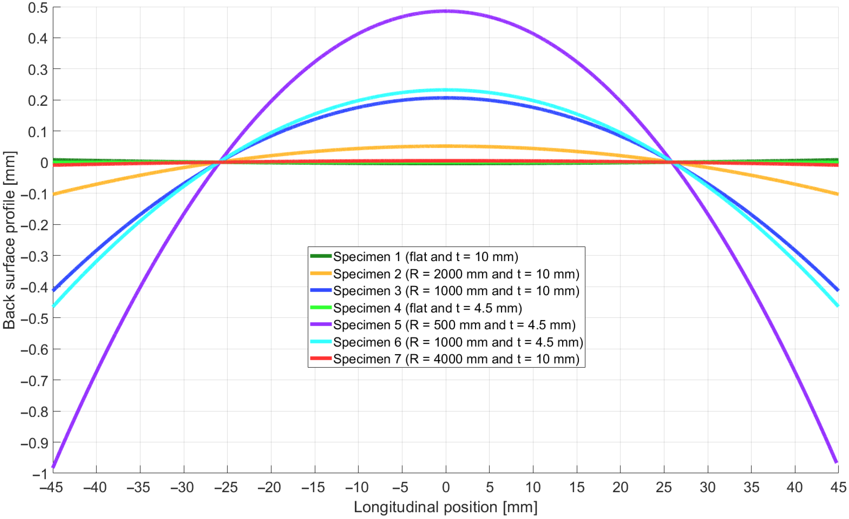
Plastic deformations found in some of the specimens were expected before testing, and are easily avoided by increasing bending radius, as seen for example in testpiece 6, which was subjected to lower maximum stresses due to the larger bending radius. As this test also showed a significant introduction of compressive surface residual stresses, increasing the bending radius solves the issue without removing the benefits of PAM. Considering this effect, tests 1, 4 and 6 did not show any plastic deformation. However, tests that surpassed the yield stress near the surface reached a maximum plastic deformation (in the external surface) of 0.04% in test 2, 0.29% in test 3 and 0.24% in test 5. Residual deformations due to excessive bending are visually represented in Figure 5.
A reasonable concern of the selected stress levels is why yield stress was surpassed and plastic deformation was allowed. Using a higher curvature than the maximum in the elastic regime was selected in some of the testpieces in order to verify that the proposed method to calculate the effect of PAM (using the introduced elastic stress) is useful in a wider range of cases; that is, if only elastic deformations were introduced, it could not be said that final residual stresses only depend on elastic stress and not on total stress. That said, it is important to clarify that for industrial applications, plastic deformations are generally not desired, so a situation closer to that of test case 6 (without plastic deformation) would be used.
The second group of geometry errors is more complex, as it depends both on the bending-induced deformation and the machining operation itself. In the non-prestressed tests (1 and 4), all milling passes were parallel and coplanar. If this was also the case under bending loads, final slots would have shown non-uniform depths from pass to pass. To avoid this issue, the trajectories remained parallel, but instead of being coplanar, they were defined as the generatrices of a cylinder coaxial with the curved surface of the fixture, as detailed in Section 3. This way, the effect of bending is easily compensated, leading to a uniform depth slot, as if no bending was applied. Consequently, leaving aside the effect of plastic deformations, the slot depth was consistent with a maximum deviation of about 10 μ m, in the same range as without prestressing.

4.3. Cutting Forces

In previous work [15], it was pointed out that when PAM is applied, as the material is closer to its ultimate stress, cutting operations could need lower forces to remove material. However, in that research, no significant changes were seen in cutting forces. Later, using bending loads in pocket milling operations [16], a notable reduction in cutting forces (up to a 65 %) was found. In the present research, cutting forces were measured using the Kistler 9255B dynamometric table beneath the fixture. Since the same measuring and machining conditions were used in all cases, the recorded signals allowed a direct comparison between prestressed and non-prestressed tests. The variation in all three force components (Fx, Fy and Fz) was analysed.
The comparison showed no relevant effect of PAM on cutting forces in the present ball-end copy-milling operation. In all cases, the observed variations remained below 4% and did not show any systematic dependence on the use of prestressing. Average force values in all tests were close to 5 N in X direction (traverse to feed), 10 N in Y direction (feed direction) and 4 N in Z direction (normal to the surface). These results induce us to think that, as proposed by Á. Sáinz de la Maza García et al. [15], the effect of PAM on cutting forces is highly dependant on the machining operation and cutting conditions. For now, results have never shown an increase in cutting forces when machining under externally applied loads but, as results do not point towards the same direction, further research is needed in this line to understand if PAM is a viable method for reducing cutting forces in certain machining operations.

4.4. Surface Roughness

Surface roughness was measured after machining and unclamping on the slot floor using an Alicona Infinite Focus G5 focus variation microscope. Measurements were taken in the traverse direction (direction of maximum roughness) at the centre of the machined area for all specimens. The Ra and Rz parameters were selected for comparison.
Unlike in [15], in this work, workpiece clamping was performed keeping the testpieces directly in contact with the fixture, so both deformations and vibrations were limited. Accordingly, surface roughness was not affected by prestressing in the ball-end copy-milling operations. All tests generated surfaces of almost equal roughness within a 5% variability: about 1 μ m Ra average roughness and 5 μ m Rz peak-valley roughness in all tests. This is consistent with the findings by Á. Sáinz de la Maza García et al. [16] in a similar situation during pocket-milling operations.

5. Conclusions

During the development of the research summarized in the present article, promising results were obtained; however, further research is needed to apply PAM under bending loads in ball-end copy-milling operations in real, industrial components. After analysing the results obtained, the following conclusions can be drawn:
  • Applying bending loads during ball-end copy-milling operations improves surface integrity by introducing more compressive surface residual stresses.
  • In performed tests, compressive surface residual stresses were increased from 30 MPa up to 180 MPa.
  • Introduced surface residual stresses can be predicted as σ x x P A M R e s = σ x x N o P A M R e s σ x x e l a s t i c .
  • Prestress-Assisted Machining (PAM) under bending loads has no negative effects in terms of cutting forces and surface roughness.
  • Testpieces milled under bending loads using geometrically corrected machining paths (following the deformed geometry) showed uniform slot thickness, meaning that no noteworthy geometric errors are introduced when plastic deformations are avoided.
The main contribution of this work is the extension of Prestress-Assisted Machining under bending loads from previously studied pocket-milling operations to ball-end copy-milling. In this more complex finishing operation, the results show not only that more compressive surface residual stresses can be achieved, but also that the simplified predictive framework previously proposed for pocket milling remains valid.

6. Future Research

Given the results obtained and the limitations of this study, further work on Prestress-Assisted Machining under bending loads is encouraged. The main issue found is the introduction of plastic deformations during bending, but it was done on purpose, and can be avoided by increasing bending radius. Additionally, in this research, the study was constrained to the analysis of using bending prestressing loads in ball-end copy-milling operations of flat, rectangular workpieces. Therefore, in future works, the same method should be applied to more complex geometries, such as turbine blade aerodynamic profiles. It may also be interesting for future research to study the effect of using a spherical (biaxial) bending strategy instead of a cylindrical (uniaxial) one to obtain a full compressive residual stress state in all directions in the fresh machined surface. Future work should also extend the analysis to other materials, tool geometries and cutting conditions in order to determine the quantitative robustness of the method beyond the specific configuration investigated here. Finally, the effect of PAM on cutting forces should be more deeply studied.

Author Contributions

Conceptualization, Á.S.d.l.M.G. and G.M.d.P.C.; methodology, Á.S.d.l.M.G.; software, Á.S.d.l.M.G.; validation, Á.S.d.l.M.G.; formal analysis, Á.S.d.l.M.G.; investigation, Á.S.d.l.M.G.; resources, L.N.L.d.L.M.; data curation, Á.S.d.l.M.G.; writing—original draft preparation, Á.S.d.l.M.G.; writing—review and editing, Á.S.d.l.M.G., G.M.d.P.C. and L.N.L.d.L.M.; visualization, Á.S.d.l.M.G.; supervision, G.M.d.P.C. and L.N.L.d.L.M.; project administration, L.N.L.d.L.M.; funding acquisition, L.N.L.d.L.M. All authors have read and agreed to the published version of the manuscript.

Funding

The authors would like to thank the Basque Government, university groups (grant IT1894-26), and Project TWIN5 CPP2024-011659 by the Spanish Ministry of Science, Innovation and Universities by Spanish Research Agency.

Data Availability Statement

Data available on request due to restrictions (confidentiality reasons).

Conflicts of Interest

The authors declare no conflicts of interest. However, they must clarify that they are all inventors of patent “Stress Assisted Machining Method (WO/2026/017740)”. The funders had no role in the research.

References

  1. Lloyd, J.R.T. The Effect of Residual Stress and Crack Closure on Fatigue Crack Growth. Ph.D. Thesis, University of Wollongong, Wollongong, Australia, 1999. [Google Scholar]
  2. Zawada-Michałowska, M.; Pieśko, P. Analysis of machining strategies in terms of residual stress and post-machining deformation of thin-walled element. Int. J. Adv. Manuf. Technol. 2026, 142, 2335–2358. [Google Scholar] [CrossRef]
  3. Li, Y.; Gan, W.; Zhou, W.; Li, D. Review on residual stress and its effects on manufacturing of aluminium alloy structural panels with typical multi-processes. Chin. J. Aeronaut. 2023, 36, 96–124. [Google Scholar] [CrossRef]
  4. Chen, Z.; Qian, L.; Cui, R.; Liu, J.; Zhang, Q. Machining-induced residual stress analysis and multi-objective optimization for milling process of Mg–Li alloy. Measurement 2022, 204, 112127. [Google Scholar] [CrossRef]
  5. Yue, C.; Hao, X.; Ji, X.; Liu, X.; Liang, S.Y.; Wang, L.; Yan, F. Analytical prediction of residual stress in the machined surface during milling. Metals 2020, 10, 498. [Google Scholar] [CrossRef]
  6. Guo, L.; Yang, W.; Zhang, P.; Lu, S.; Sun, J. The effect of tool posture on surface integrity during ball-end milling. Int. J. Adv. Manuf. Technol. 2025, 141, 6035–6054. [Google Scholar] [CrossRef]
  7. Qi, Q.; Zhou, J.; Ren, J.; Zhang, R.; Wang, Z.; Yin, X. Spatial 3D distribution of residual stress induced by four-axis milling TC4 V-structure with a conical ball-end cutter. J. Mater. Res. Technol. 2025, 39, 3805–3819. [Google Scholar] [CrossRef]
  8. Zhang, W.; Wang, X.; Hu, Y.; Wang, S. Predictive modelling of microstructure changes, micro-hardness and residual stress in machining of 304 austenitic stainless steel. Int. J. Mach. Tools Manuf. 2018, 130–131, 36–48. [Google Scholar] [CrossRef]
  9. Ulutan, D.; Alaca, B.E.; Lazoglu, I. Analytical modelling of residual stresses in machining. J. Mater. Process. Technol. 2007, 183, 77–87. [Google Scholar] [CrossRef]
  10. Wan, M.; Wang, D.-S.; Wen, D.-Y.; Zhang, W.-H. Enhanced prediction of residual stress in milling through considering cutter runout. J. Manuf. Process. 2024, 123, 1–12. [Google Scholar] [CrossRef]
  11. Aurrekoetxea, M.; López de Lacalle, L.N.; Zelaieta, O.; Llanos, I. In-process machining distortion prediction method based on bulk residual stresses estimation from reduced layer removal. J. Manuf. Mater. Process. 2024, 8, 9. [Google Scholar] [CrossRef]
  12. Weber, D.; Kirsch, B.; Chighizola, C.R.; D’Elia, C.R.; Linke, B.S.; Hill, M.R.; Aurich, J.C. Analysis of machining-induced residual stresses of milled aluminum workpieces, their repeatability, and their resulting distortion. Int. J. Adv. Manuf. Technol. 2021, 115, 1089–1110. [Google Scholar] [CrossRef]
  13. Schulze, V. Modern Mechanical Surface Treatment; Wiley-VCH: Weinheim, Germany, 2006. [Google Scholar]
  14. Singh, R. 12—Heat treatment of steels. In Applied Welding Engineering, 3rd ed.; Singh, R., Ed.; Butterworth-Heinemann: Oxford, UK, 2020; pp. 105–118. [Google Scholar]
  15. Sáinz de la Maza García, Á.; López de Lacalle Marcaide, L.N.; Martínez de Pissón Caruncho, G. Prestress Assisted Machining: Achieving high surface integrity in thin wall milling. Results Eng. 2025, 26, 105491. [Google Scholar] [CrossRef]
  16. Sáinz de la Maza García, Á.; Martínez de Pissón Caruncho, G.; López de Lacalle Marcaide, L.N. Pocket milling on thin slender aluminium 5083 workpieces under uniform bending loads. MM Sci. J. 2026, accepted. [Google Scholar]
  17. ISO 4288:1996; Product Specifications (GPS)—Surface Texture: Profile Method—Rules and Procedures for the Assessment of Surface Texture. International Organization for Standardization: Geneva, Switzerland, 1996.
  18. ASTM E837-20; Standard Test Method for Determining Residual Stresses by the Hole-Drilling Strain-Gage Method. American Society for Testing and Materials: West Conshohocken, PA, USA, 2020.
  19. Li, X.; Liu, J.; Wu, H.; Miao, K.; Wu, H.; Li, R.; Liu, C.; Fang, W.; Fan, G. Research progress of residual stress measurement methods. Heliyon 2024, 10, e28348. [Google Scholar] [CrossRef] [PubMed]
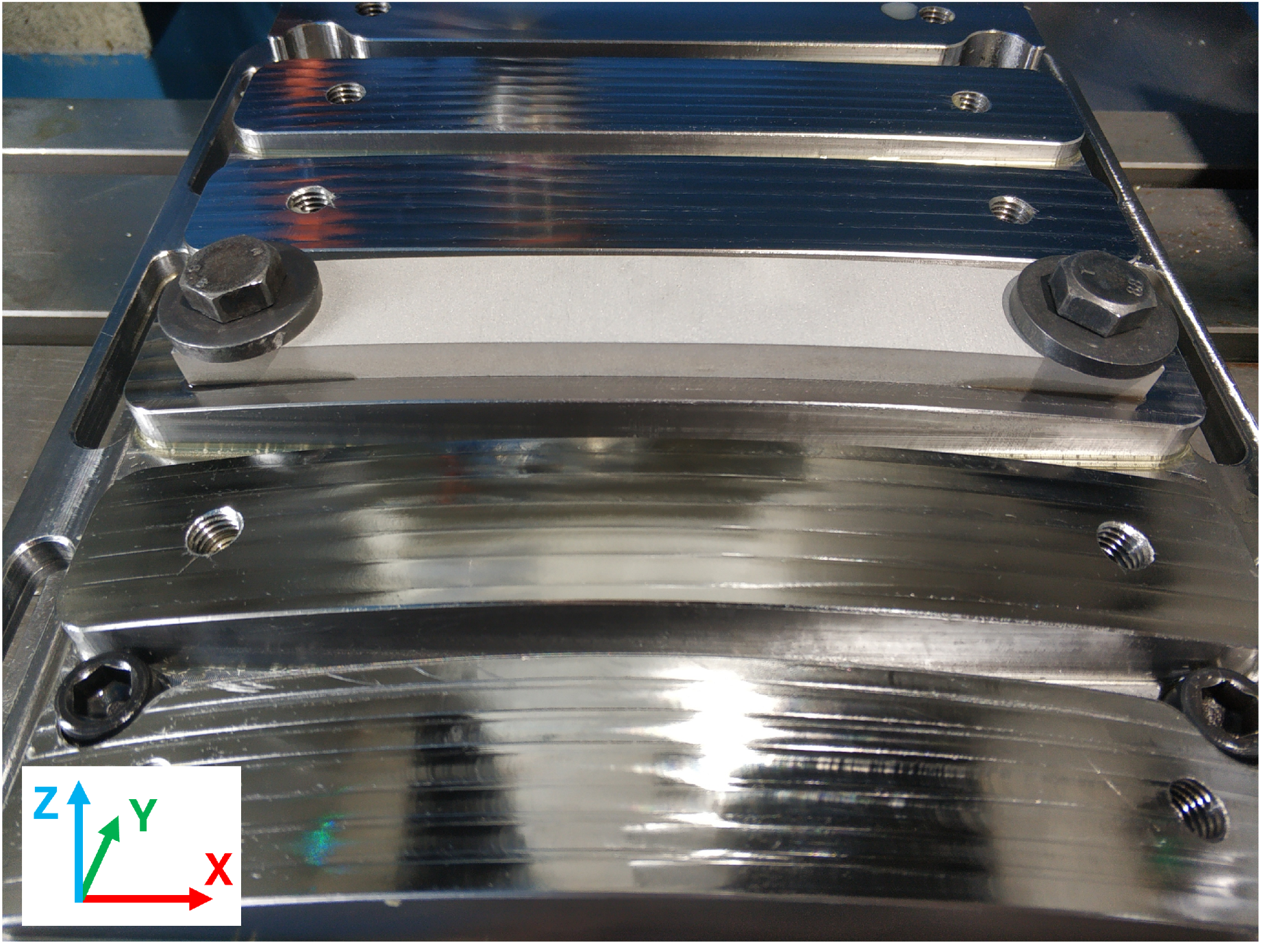
Figure 1. A 10 mm thick workpiece clamped to the bending prestressing fixture with a 1000 mm curvature radius.
Jmmp 10 00156 g001
Figure 2. Curvature error in test 5 due to clamping force.
Jmmp 10 00156 g002
Figure 3. Final geometry of a slot machined by ball-end copy-milling and main dimensions of the test specimens.
Jmmp 10 00156 g003
Figure 4. Residual stress predictions and measurements.
Jmmp 10 00156 g004
Figure 5. Final geometry of the testpieces after the machining operation. R represents the bending radius and t the thickness of each specimen.
Jmmp 10 00156 g005
Table 1. Performed tests’ key prestressing parameters.
Test NumberWorkpiece Thickness (mm)Curvature Radius (mm)
110-
2102000
3101000
44.5-
54.5500
6104000
Table 2. Machining conditions used for ball-end copy-milling tests.
Cutting speedFeed per toothWorkpiece material
115 m/min (12,000 rpm)0.15 mm (3600 mm/min)Al 5083
   
Tool materialTool diameterNumber of flutes
HSS-Co8 mm2 flutes
   
Axial depth of cutRadial depth of cutMachining centre
0.3 mm0.3 mmKondia HS1000
Table 3. X-Ray diffraction residual stress measurement conditions.
X-Ray sourceWavelength (Å)Diffraction plane (H K L)Irradiated area (mm2)
Cr-Kα12.293 1 11
    
Diff. angle 2 θ (°) s i n 2 ( ψ ) rangeMax. uncertainty (MPa)Num. tilt angles
139.308−0.7 to 0.7±516
Disclaimer/Publisher’s Note: The statements, opinions and data contained in all publications are solely those of the individual author(s) and contributor(s) and not of MDPI and/or the editor(s). MDPI and/or the editor(s) disclaim responsibility for any injury to people or property resulting from any ideas, methods, instructions or products referred to in the content.