


Abstract
This study investigates the influence of design factors and key process parameters—including explosive welding (EXW), rolling, and laser processing—on the formation, microstructure, and tribological properties of Ti–Cu–Ni intermetallic coatings. A combined manufacturing approach was employed, starting with the EXW of an MN19 cupronickel alloy to a VT1-0 titanium substrate, followed by multi-pass rolling to achieve a cladding thickness of approximately 0.3 mm. Subsequently, laser surface remelting was performed to facilitate controlled mass transfer and homogenization within the reaction zone. Numerical simulation using COMSOL Multiphysics v. 5.4 was utilized to optimize the thermal cycles and determine the ideal energy density (42 J/mm2) for phase formation. The results demonstrate that the primary structural components of the coatings produced under optimal conditions are solid solutions based on the ternary-modified titanium cuprides Ti2Cu(Ni) and TiCu(Ni). The transition from a layered bimetal to a finely dispersed intermetallic structure significantly enhances the surface characteristics. This specific phase composition provides a sustained microhardness of ~5 GPa across the coating cross-section. Comparative wear tests against fixed abrasive revealed that the wear resistance of the Ti–Cu–Ni coatings is 2.5 times higher at room temperature and 1.5 times higher at 600 °C than that of the base VT1-0 titanium.
1. Introduction
The high specific strength and corrosion resistance of titanium and its alloys have led to their widespread use in power engineering, automotive manufacturing, aerospace engineering, aircraft construction, and other industries [1]. However, the use of titanium alloys in friction units is limited by their low wear resistance. Regardless of the alloying type or system, titanium alloys are prone to seizure during friction and, as a result, to significant wear and mechanical damage of the contact surfaces.
To improve the tribological properties of titanium alloy components, wear-resistant intermetallic coatings based on titanium cuprides are applied to their surfaces [2,3,4]. The wear resistance of Ti-Cu coatings is due to the relatively high hardness of the sliding surface (4.5–5.5 GPa) and high chemical activity in gas atmospheres, which lead to the formation of microscopic films on the sliding surface [5,6]. The main disadvantage of binary titanium cuprides is low-temperature brittleness and low fracture toughness at room temperature. The introduction of additional phases into the coating composition through alloying, for example, with nickel, will not only improve their mechanical properties but also enables unique mechanisms that operate during structure formation only in multiphase alloys [7,8,9].
Analysis of the literature shows that titanium cupride-based coatings are primarily produced by the following methods: electrolytic deposition, laser cladding, gas tungsten arc welding (GTAW), cathodic arc deposition, mechanical alloying, electrospark sintering, and pack cementation. Generally, these methods involve heating and holding in chemically active media containing the applied substance, or high-energy impact on films or layers of the applied material.
The technology for creating coatings by electrolytic deposition followed by diffusion annealing [10,11,12,13] involves immersion in acidic sulfate baths for copper plating to create a uniform layer approximately 10–40 µm thick on a titanium or titanium alloy substrate. Subsequent diffusion annealing is carried out in an argon atmosphere to protect the surface from oxidation at a temperature of 820 °C (the duration varies depending on the thickness of the final diffusion layer). The advantage of coatings produced by this method is the absence of pores and microcracks while maintaining high hardness and sufficient ductility. Disadvantages include low process productivity, a long cycle of preparatory operations, and significant emissions of harmful substances (e.g., chlorine and acidic fumes).
Laser processing [14,15,16,17] involves the preliminary application of a thin layer of an alloying component (primarily in powder form) and its subsequent melting with a laser beam along with the substrate. When forming a coating by laser processing of the titanium surface with copper in a local volume up to 35 μm thick, an alloy with a microhardness of approximately 5.5 GPa is formed. An increase in the microhardness of the coating is achieved by varying the laser beam speed, the thickness of the pre-applied copper coating, and the introduction of additional alloying elements such as Ni or Cr. However, an increase in microhardness is accompanied by a reduction in the ductility (or fracture toughness) of the surface layer. The main disadvantages of laser processing technology are relatively low productivity and poor surface finish, requiring subsequent machining.
The GTAW surfacing method using a non-consumable electrode [7] provides high productivity and the ability to produce thick coatings. However, their structure is characterized by severe liquation inhomogeneity, and an extended (up to 0.5 mm) remelt zone forms between the coating and the substrate. Ti-Cu-Ni coatings were obtained on the surface of a Q235 low-carbon steel substrate. Their wear resistance was twice that of a coating made of industrial aluminum bronze.
Ion-plasma coatings and magnetron sputtered coatings are characterized by high density and good adhesion. This method allows for the application of coatings of uniform thickness to complexly shaped objects. However, the method requires rather sophisticated equipment and is characterized by low deposition rates. The authors [18,19,20,21] obtained coatings of varying compositions (from Ti–21% Cu to Ti–65% Cu) with a thickness of 2–5 μm on a steel substrate. The Ti–65% Cu coating demonstrated the best tribological properties under conditions of wear of disk-rod specimens under sliding friction.
Mechanical alloying [22] involves applying coatings using vibratory or planetary mills. This method produced Ti–Cu coatings approximately 100 µm thick, consisting of an inner composite layer and an outer amorphous layer. The coating increased the wear resistance of the copper substrate threefold. A disadvantage of this method is excessive gas saturation during prolonged mechanical alloying, which contributes to the formation of defects and the production of a low-quality coating.
The technology of electrospark alloying is applicable for depositing coatings on both copper and titanium bases [23,24,25]. Coatings with a thickness of 30–50 μm obtained by this method have a fine-grained structure, which is heterogeneous in composition (in addition to titanium and copper, intermetallic compounds CuTi3, CuTi, Cu4Ti3, Cu3Ti were detected). The microhardness of the formed layers reached 6.7 GPa. Samples with a closer equimolar ratio of copper and titanium had the highest hardness. Tribological tests have shown that the Ti-Cu coating can increase the wear resistance of the Ti6Al4V alloy surface by 11 times. Disadvantages of the method: small thickness of the applied layer, its high roughness and porosity; relatively low processing productivity.
The essence of the pack cementation method [26] consists of applying a powder mixture of NH4Cl, Ti and Al2O3 to the copper surface, followed by holding at a temperature of 800 °C for 6 h. The microhardness of the formed coating in the direction from the copper substrate to the interface smoothly increases, which is due to the formation of a solid solution and intermetallic compounds TiCu4, TiCu and Ti2Cu. A study of the wear resistance of the coating showed that the weight loss in the coated samples during prolonged sliding under a load of 30 N is significantly less than in copper samples. The higher wear resistance of the coating is due to the high hardness of the intermetallic compounds and their low coefficient of friction (the average coefficient of sliding friction in samples coated with intermetallic compounds under loads of 30 and 60 N was 0.8 ÷ 0.15). Delamination is the dominant wear mechanism for samples obtained by this method, and the method itself is relatively labor-intensive, has low productivity, and is characterized by negative long-term high-temperature effects on the protected blank.
Thus, an analysis of research conducted in recent years suggests that traditional methods for creating intermetallic coatings based on titanium cuprides are inefficient and often fail to achieve the required coating thickness and mechanical properties. The aim of this study is to investigate the structure and properties of multicomponent intermetallic coatings of the Ti-Cu-Ni system, produced on a titanium surface using a combined approach, including preliminary deposition of a thin layer of copper-nickel alloy on the titanium substrate via explosive welding (EXW) and pressure treatment (rolling), followed by laser processing of the resulting surface.
2. Materials and Methods
Commercially pure titanium plate (VSMPO-AVISMA Corporation, Moscow, Russia) with a thickness of 6 mm was used as the substrate. A copper–nickel alloy sheet (MTSENSKPROKAT, Mtsensk, Russia) with a thickness of 0.60 mm was used as the cladding material. The chemical compositions of initial materials are presented in Table 1 and Table 2.
Table 1.
Chemical composition of VT1-0 titanium (mass %).
Table 2.
Chemical composition of MN19 copper–nickel alloy (mass %).
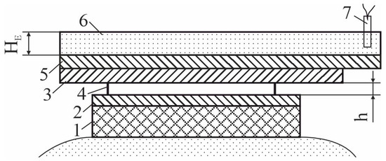
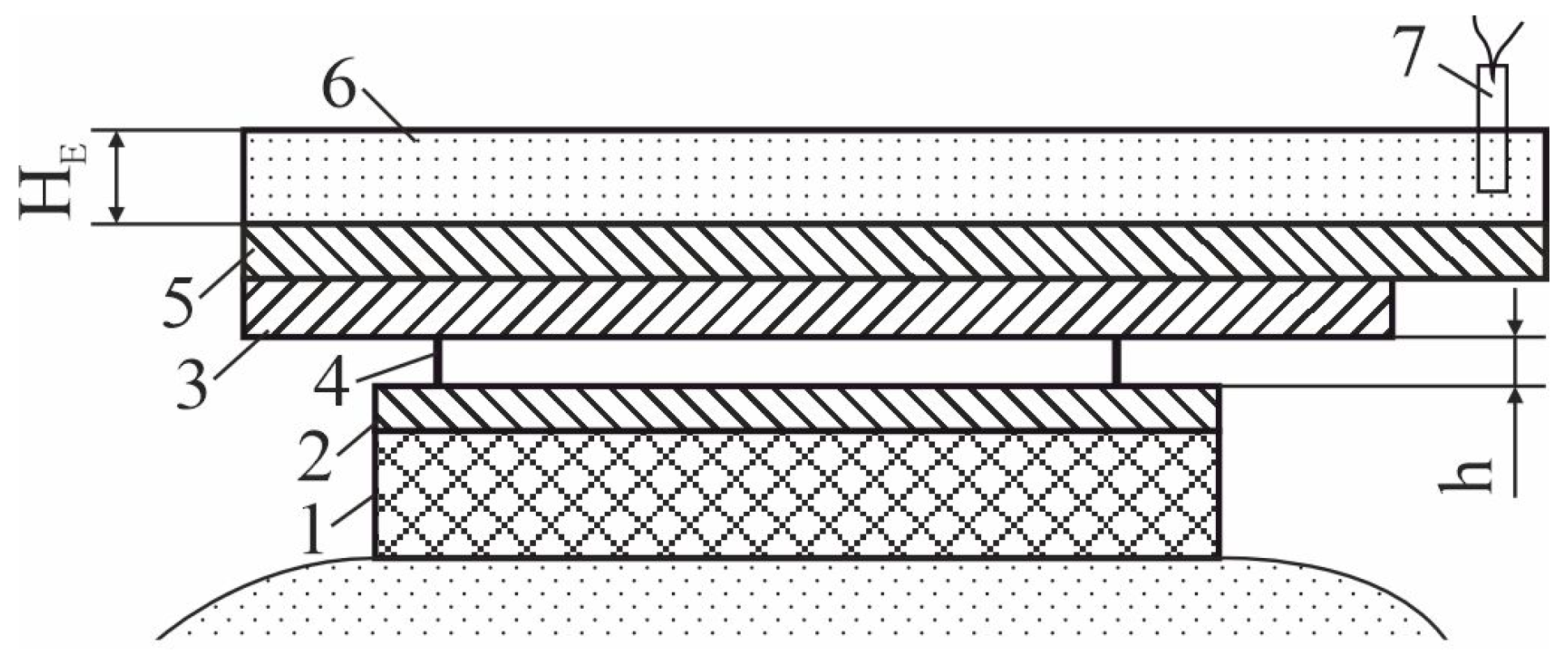
The MN19 alloy thickness was chosen as 0.6 mm to minimize the required reduction ratio during subsequent rolling. On the one hand, this required the driver plate in the welding scheme; on the other hand, it allowed the use of industrial explosive ammonite No. 6ZhV with a detonation velocity of 1900 m/s. Explosive welding of MN19 alloy with VT1-0 titanium was performed using a plane-parallel scheme (Figure 1). The minimum impact velocity (Vi) required to achieve a strong bond of metals was calculated using a methodology developed at Volgograd State Technical University. This involves estimating the specific energy expended on plastic deformation of the metal (W2cr), followed by the determination of dynamic (impact velocity Vi, collision point velocity Vc) and technological (H—explosive height, h—stand-off distance) parameters. When welding dissimilar metals, the value of W2kr occupies a position close to or equal to the necessary critical energy consumption of the softer metal. This is due to the localization of plastic deformation in the weld zone and the need to activate the surface of the harder layer only to a level where the joint strength matches the properties of the less durable metal. Details of the EXW parameter calculations are presented in [27]. Calculated EXW modes are shown in Table 3.
Figure 1.
Explosive welding scheme. 1—chipboard, 2—titanium alloy, 3—copper–nickel alloy, 4—stand-off distance (h), 5—driver plate, 6—explosive charge (HE height), 7—electric detonator.
Table 3.
Explosive welding modes.
Peel strength tests of the explosively welded joint were performed using the Lloyd LR5K+ testing system (Lloyd Instruments Ltd., Bognor Regis, UK).
The explosively welded bimetal was cut into blanks with dimensions of 100 mm × 100 mm and rolled on the “DUO” mill (roll diameter 130 mm) (VNIIMETMASH, Moscow, Russia) to reduce the thickness of the copper-nickel alloy layer. Rolling was performed without tension or straightening in three passes. The rolling start temperature in each pass was 500–550 °C. The rolling start temperature was chosen for the following reasons: at temperatures up to 500 °C, oxygen is practically insoluble in titanium; its significant dissolution begins only at 550–600 °C; the formation of intermetallic phase nuclei in the studied alloying systems does not occur at 500–550 °C [28]. After each pass, samples were taken to measure the reduction in the individual layers and the composite as a whole.
Laser processing (LP) was performed using a “TL 1200” system (TechnoLaser, Shatura, Russia) with maximum power of 1400 W (peak power up to 1600 W). The scanning speed varied from 0.5 to 1.2 m/min with a spot diameter of 1–4 mm. The overlap coefficient during laser processing was 0.5.
During LP, interconnected heat and mass transfer and micrometallurgical processes occur in the surface layer of the workpiece [29]. As the laser beam moves, the molten metal is forced toward the rear of the melt pool due to mass transfer (the integral effect of vapor pressure, surface tension gradients between the central and rear portions of the pool, and turbulent melt flows). Marangoni thermocapillary convection causes mixing of the molten cupronickel cladding with the titanium substrate, saturation of the titanium surface with copper and nickel, formation of intermetallics, and partial homogenization in the remelting zone (RMZ). The volume of molten metal in the RMZ depends primarily on the laser energy density E and the thickness of the MN19 cupronickel cladding.
The E parameter is determined by the following relation:
where P is the laser power (W); d is the beam diameter at the contact spot (mm); and V is the scanning speed (mm/s).
E = P/(d·V),
To simulate temperature fields and the melt pool geometry on the titanium surface, depending on the laser source velocity across the bimetallic surface, all other laser processing parameters being equal, COMSOL Multiphysics v. 5.4 with the “Heat Transfer in Solids” module was used. This module includes the following conditions: Heat Flux (laser heat source with a Gaussian beam profile), Heat Flux (convective cooling with a heat transfer coefficient of h = 5 W/(m2·K)), Thermal Insulation, Open Boundary, and Diffuse Surface (surface-to-ambient radiation with an emissivity of 0.6). The computational domain was defined in 3D, simulating a moving heat source with specified power and radius across the MN19 alloy surface.
The 3D model utilized a temperature-dependent thermophysical property dataset for the MN19 and VT1-0 alloys. The properties were sourced from the integrated COMSOL Multiphysics Material Library. For the VT1-0 titanium substrate, the Ti Grade 1 alloy was used as a direct equivalent. For the MN19 cladding alloy, UNS C70600 was selected as the most suitable analog due to its closely matching thermophysical characteristics.
The laser heat source was modeled as a surface Gaussian distribution with an absorption coefficient of 0.35 (taking into account the rapid surface oxidation during the process).
To ensure computational accuracy, a non-uniform mesh was employed. The results of the mesh independence study showed that a maximum element size of 0.4 mm in the heat-affected zone is sufficient to provide stable and mesh-independent solutions.
The simulation was performed using a time-dependent solver with a constant step of 0.01 s, which was sufficient to capture the thermal gradients induced by the moving heat source.
To simplify the numerical procedure, the model was developed without considering phase transitions. This assumption is justified as the study primarily focuses on the temperature field distribution rather than the fluid dynamics of the melt pool.
When simulating the temperature fields and the melt pool shape on the surface, the displayed temperature range was selected from 800 to 2000 °C. The heating-cooling cycle was defined as the time interval between the start of heating and cooling of the entire sample below the polymorphic transformation temperature. The following criteria were used to validate the model’s accuracy:
- Correlation between the calculated melting temperature of the MN19 alloy (1200 °C) and the observed melting boundary of the cladding layer.
- Correlation between the simulated temperature zone of active titanium grain growth (880 °C) and the experimental boundary of the coarsened grain zone.
The cross-sectional microstructures of samples were evaluated using scanning electron microscopy (SEM) (Versa 3D, FEI, Morristown, NJ, USA). The elemental composition was determined via energy-dispersive X-ray spectroscopy (EDS) using the Oxford 51N1286 AZtecLive Expert system equipped with an Ultim Max 65 detector (Oxford Instruments, Abingdon, UK). To perform the microstructure observation and chemical analysis in SEM, the sample cross-sections were ground using abrasive papers and then mirror-polished using diamond slurry with a particle size of 0.5 μm. Prior to this, the specimens were mounted in conductive polyester resin using the POLYLAB S50L metallographic press (KEMIKA, Moscow, Russia).
Metallographic studies of the laser treated specimens were carried out using an optical microscope (Olympus BX-61, Olympus Corporation, Tokyo, Japan) equipped with the AnalySIS Pro 32 software (Soft Imaging System GmbH, Münster, Germany).
A Bruker D8 Advance Eco X-ray diffractometer (XRD) (Bruker AXS GmbH, Karlsruhe, Germany) in the Bragg–Brentano geometry with Kβ filtered CuKα radiation (λ = 0.15406 nm) was used to identify the intermetallic phases.
The microhardness was measured on a PMT-3M device (JSC LOMO, Saint Petersburg, Russia) with an indenter load of 50–100 g.
Wear tests using the Khrushchev–Babichev method were carried out on a setup similar to the Kh4-B machine, designed for testing materials for wear against a fixed abrasive in air atmosphere (KK19XW sandpaper with a grain size of 32-H), under a static load of 3.5 N. The relative wear resistance of the coatings was estimated using the formula:
where ΔG1 is the mass loss of the standard (titanium VT1-0) (g); ΔG2 is the mass loss of the coated sample (g).
ε = ΔG1/ΔG2,
The sample, coupled with the abrasive surface, moved along the Archimedes spiral, which, with a grinding paper diameter of 340 mm, provided a path of 30 m in length.
The study of the processes of adhesive/cohesive destruction of coatings, as well as the determination of their hardness by scratching, was carried out using a PMT-3M microhardness tester (JSC LOMO, Saint Petersburg, Russia). A Vickers tetrahedral diamond pyramid with an apex angle of 136° was used as an indenter. Scratching was carried out on the surface of the metallographic sample with the pyramid edge so that the diagonal of the pyramid base was located along the direction of indenter movement. The indenter was moved from the substrate to the coating perpendicular to the interface. The horizontal driving force was applied through a microscrew to the rotating platform of the microhardness tester. The scratches 1000 μm long were applied in the plane of the metallographic specimen from the Ti substrate through the coating and beyond its limits. The uniform movement speed of the table was 20 μm/s. The vertical load on the indenter varied within 1–5 N.
The value of scratch hardness (H, MPa), which characterizes the resistance to destruction, was determined using Formula (3) [30]:
where F—normal force, N, b—scratch width, mm.
H = (0.3782 × F)/b2,
To ensure the reproducibility of the results, all mechanical and tribological tests (microhardness, peel strength, scratch test, and wear resistance) were performed on at least three duplicate samples for each condition. The experimental data are presented as mean values ± standard deviation.
3. Results and Discussion
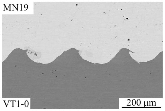
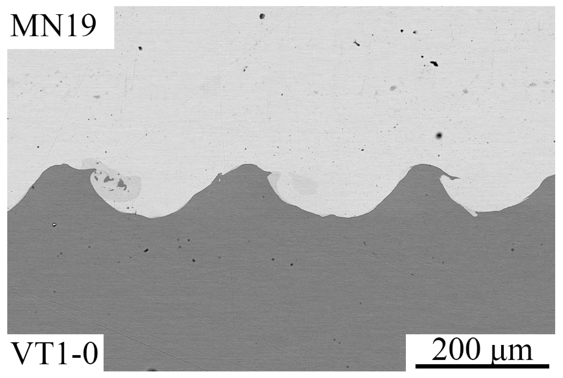
After EXW, the MN19 + VT1-0 joint boundary exhibits a characteristic wavy profile (Figure 2) with localized melt pockets (molten metal areas). These areas are located within the vortices of the waves formed on the MN19 alloy side. Most of these areas do not have direct contact with the VT1-0 titanium. The relative length of the molten metal areas was 48–54%, and their thickness at certain points along the joint boundary reached 50 µm.
Figure 2.
SEM image of the MN19 + VT1-0 joint boundary after EXW.
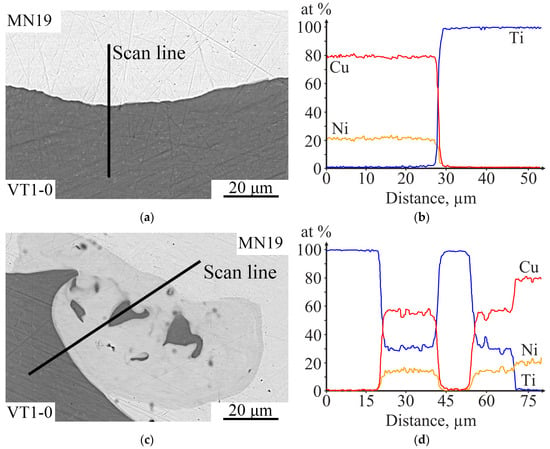
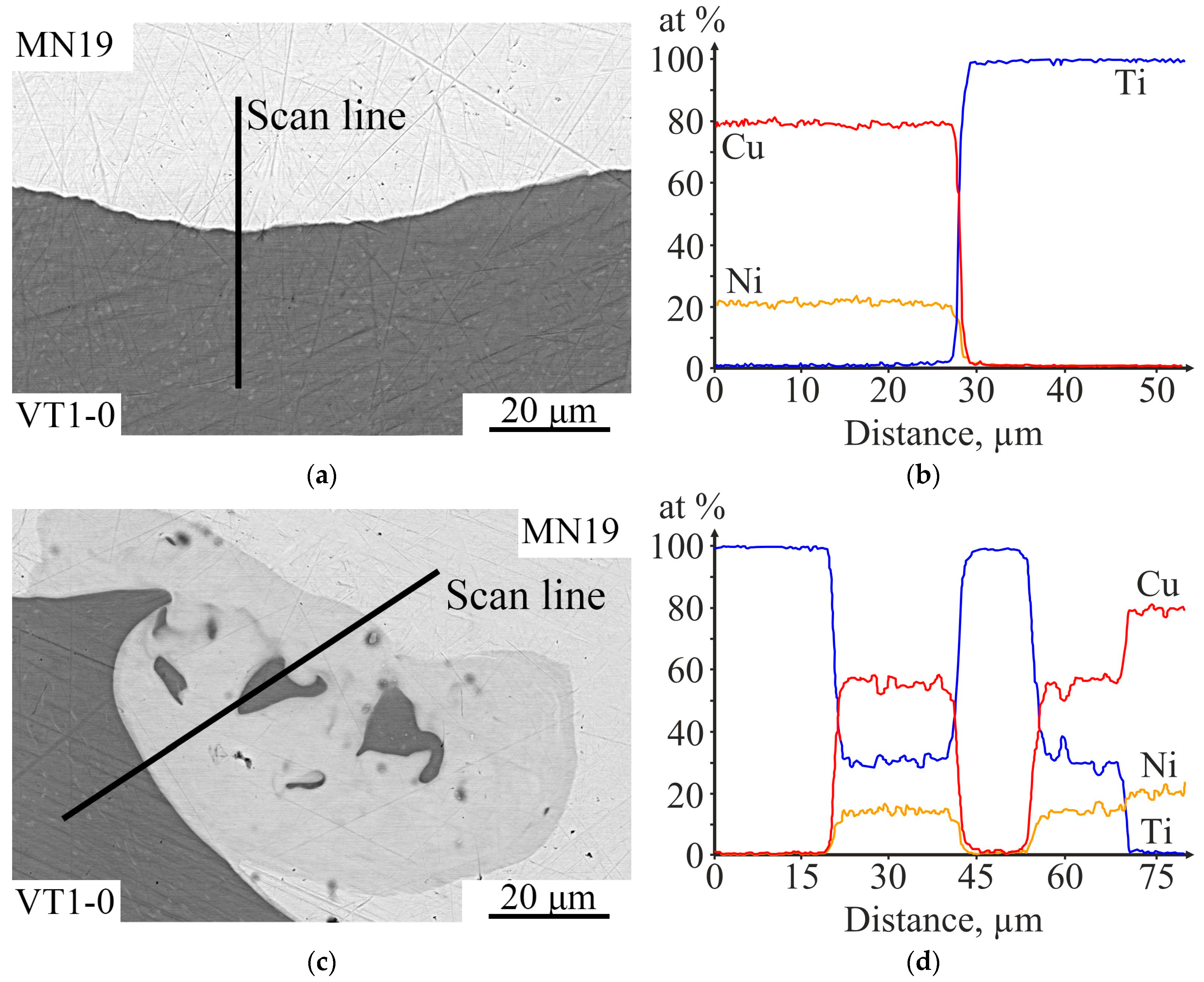
Studies have shown that the molten metal structure contains areas with different Cu and Ti contents: lighter regions (55 at.% Cu, 30 at.% Ti) and darker regions (60 at.% Cu, 25 at.% Ti). The Ni content in the molten metal is approximately 15 at.%. The structure of some melt pockets contains inclusions of pure titanium (Figure 3). The EDS line scan in Figure 3b illustrates the elemental distribution across the interface of the compound lacking melt pockets, whereas Figure 3d clearly demonstrates the compositional variation across a specific melt pocket.
Figure 3.
SEM images of the MN19 + VT1-0 joint boundary: (a) a region free of melt pockets, (c) a region containing a melt pocket, and (b,d) the corresponding EDS spectra.
According to the isothermal section of the Ti-Cu-Ni phase diagram [31], the most probable composition of the molten metal should correspond to the ternary intermetallic compound CuNiTi (τ1). With a nearly constant Ti content (33–35 at.%), this phase can contain varying Cu and Ni content over a wide range. Considering the highly non-equilibrium conditions of crystallization of the melt pockets [32], the formation of such compounds with a slightly deviated stoichiometry can be expected. The microhardness of the melts pockets fluctuates between 6 and 7 GPa (±0.2 GPa). Due to severe plastic deformation (SPD), the hardness of the titanium at the interface increased to 3.1 ± 0.1 GPa, while the MN19 alloy reached 1.8 ± 0.1 GPa, which is approximately 1.3 times higher than the initial values (before welding). Peel strength tests showed that the bond strength of the bimetallic samples ranges from 290 to 350 MPa, with failure occurring within the MN19 layer.
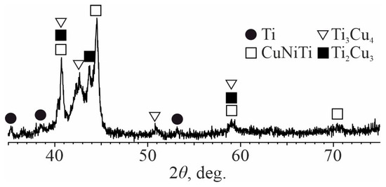
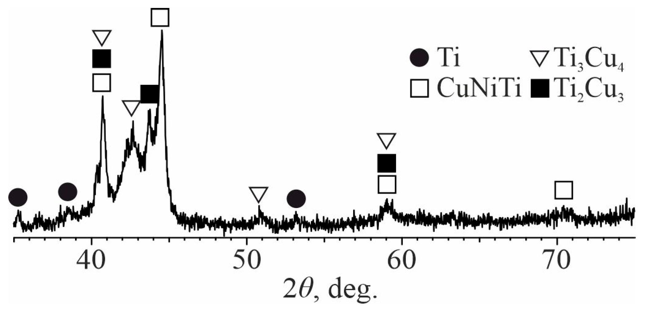
The sufficient thickness and extent of the molten metal allowed for the evaluation of its phase composition using XRD after peel tests. Figure 4 shows the XRD pattern of the molten metal, which indicates that the main phases present in the melt are CuNiTi (τ1), Cu3Ti2, and Cu4Ti3. According to literature data, the latter two phases can dissolve ~5 and 7 at.% Ni, respectively [33].
Figure 4.
XRD pattern of molten metal at the MN19 + VT1-0 joint boundary.
The layer-by-layer and total thickness reduction of the MN19–VT1-0 composite during rolling after EXW are presented in Table 4. Analysis of these results showed that the initial difference in the mechanical properties of the layers leads to non-uniform deformation at low reduction ratios, which subsequently levels out. Similar deformation behavior of the constituent layers was observed by the authors [34] when studying the structure of layered Ti/Cu composites produced by the accumulative roll bonding. The thickness of the copper-nickel alloy after the third rolling pass was ~0.3 mm.
Table 4.
Influence of the total reduction ratio on the layer thickness during rolling.
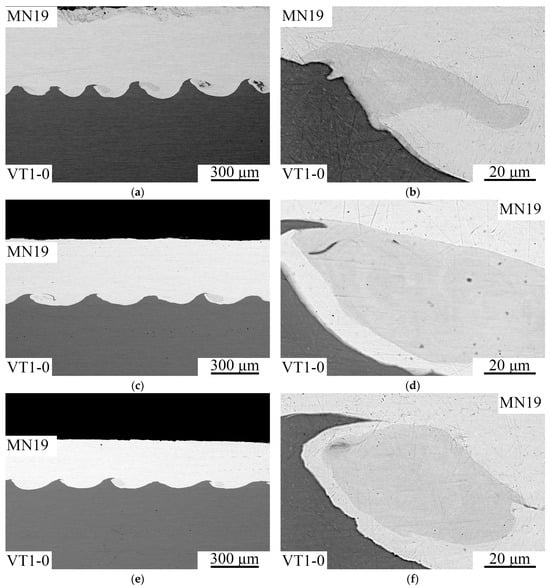
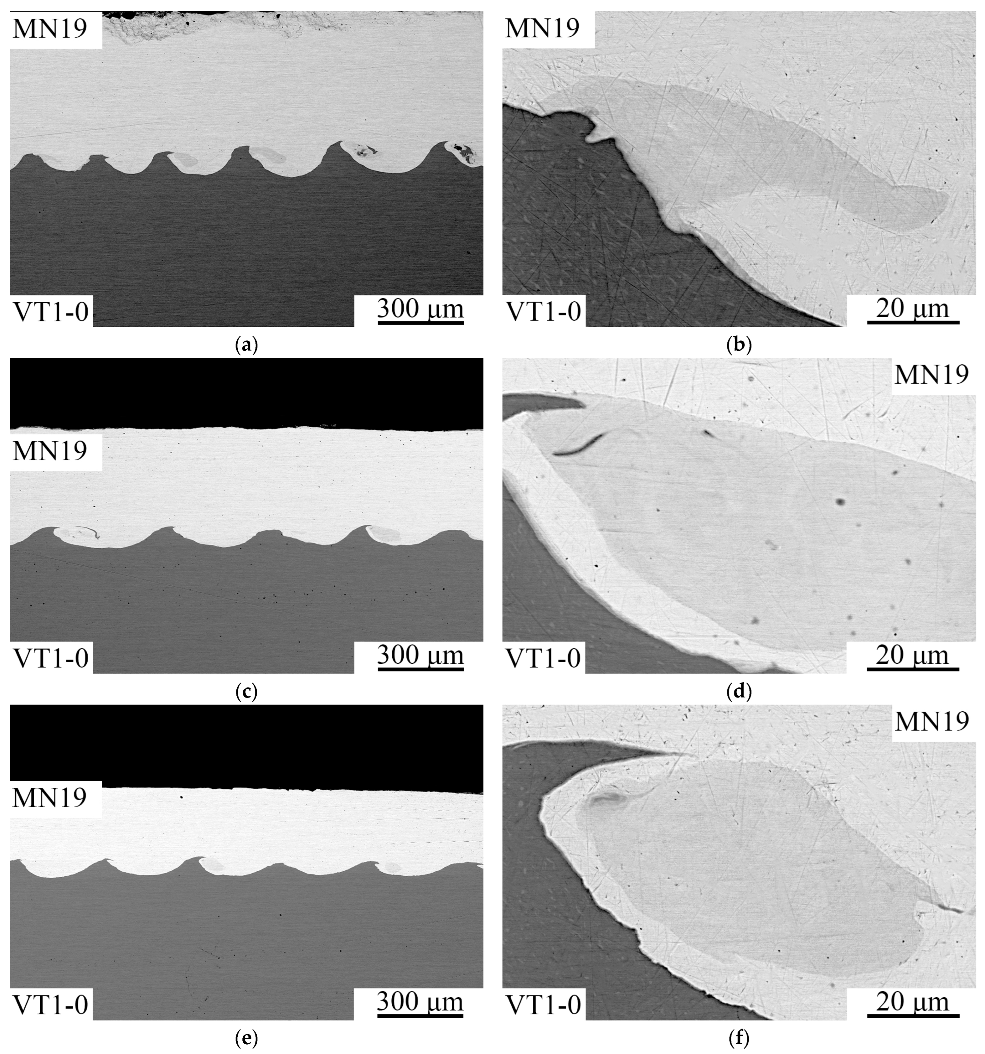
Metallographic studies of the transition zone microstructure in the explosively welded composites revealed a flattening of the wavy interface (Figure 5). Localized melt pockets were not deformed and retained their shape and size. The composition of the molten metal areas remained unchanged from their composition after EXW, corresponding to the CuNiTi (τ1) ternary intermetallic compound with a reduced titanium content.
Figure 5.
SEM images of the MN19 + VT1-0 joint boundary (a,c,e) and the melt pockets (b,d,f) after EXW and subsequent rolling: first pass (a,b), second pass (c,d) and third pass (e,f).
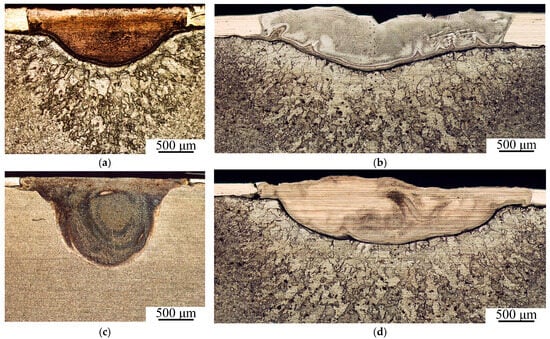
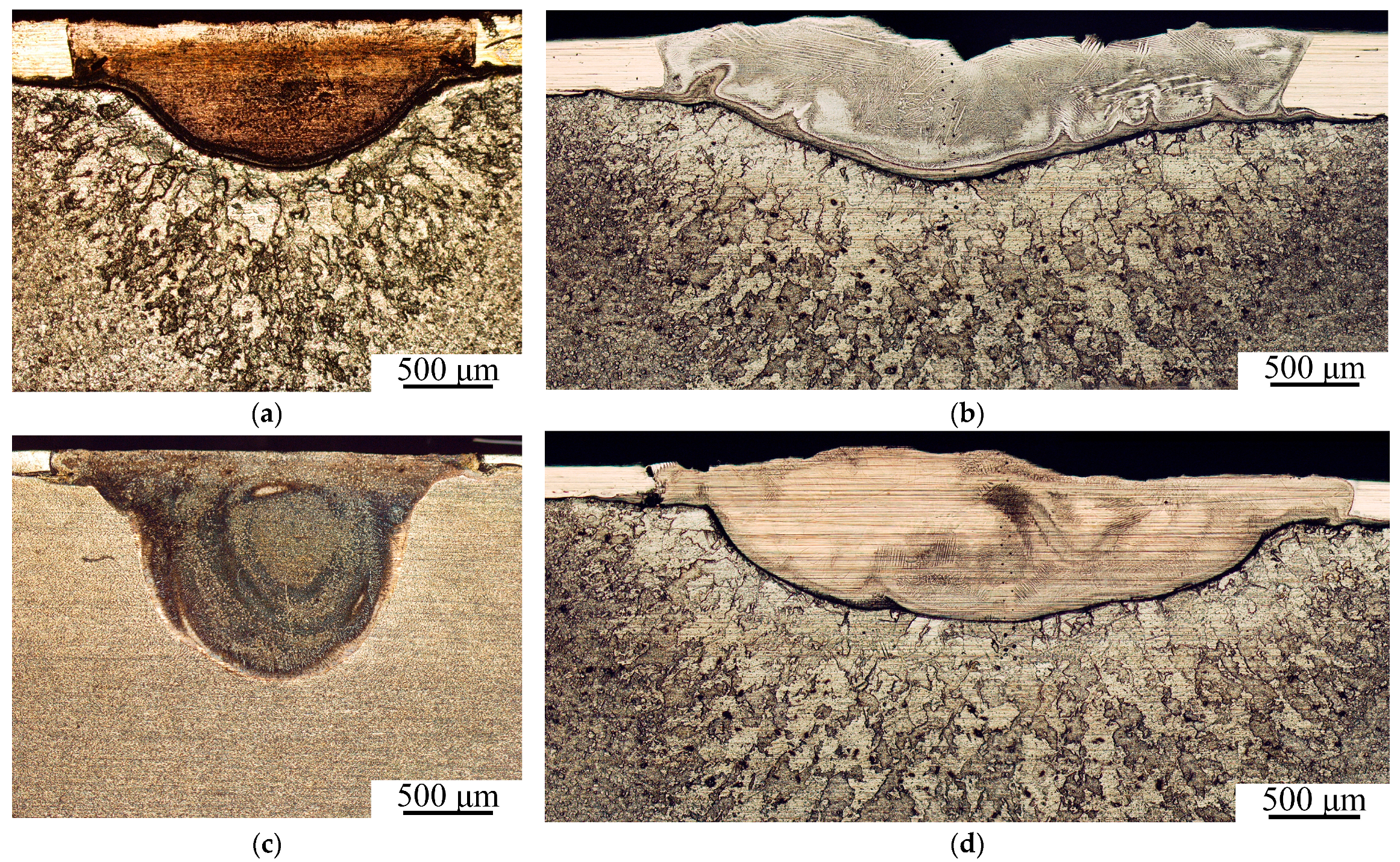
Metallographic analysis (Figure 6) showed that, within the studied range of laser power and scanning speed, the contact spot diameter influences the width, symmetry, and surface profile of the RMZ. All other things being equal, a 2 mm contact spot diameter ensures a symmetrical RMZ and a smooth coating surface. Laser processing with a spot diameter smaller than 2 mm is inefficient due to reduced process productivity. Conversely, increasing the diameter reduces the RMZ depth because of the lower energy delivered per unit surface area. Increasing the diameter beyond 4 mm results in the formation of an asymmetrical RMZ and a wavy coating surface profile.
Figure 6.
Microstructure of the MN19 + VT1-0 joint boundary after laser processing at d = 2 mm (a,c) and 4 mm (b,d) (V = 0.8 m/min, P = 1400 W): (a,b) specimen after EXW (thickness of the MN19 layer h ≈ 0.6 mm); (c,d) specimen after EXW and rolling (thickness of the MN19 layer h ≈ 0.3 mm).
Experiments have shown that to form the RMZ with an optimal structure, the thickness of the MN19 copper-nickel layer during laser processing should not exceed 0.4–0.5 mm. Increasing the copper-nickel layer thickness necessitates higher laser power to achieve the required penetration depth (Figure 6), which will lead to overheating and boiling of the remelting zone.
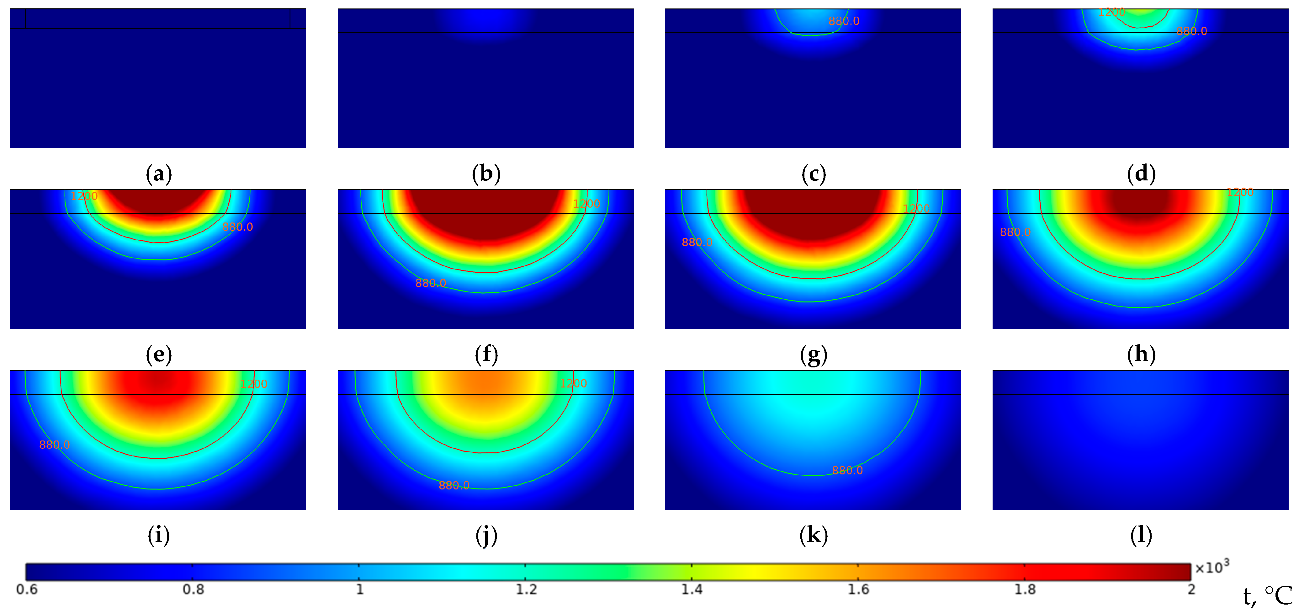
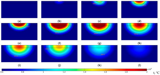
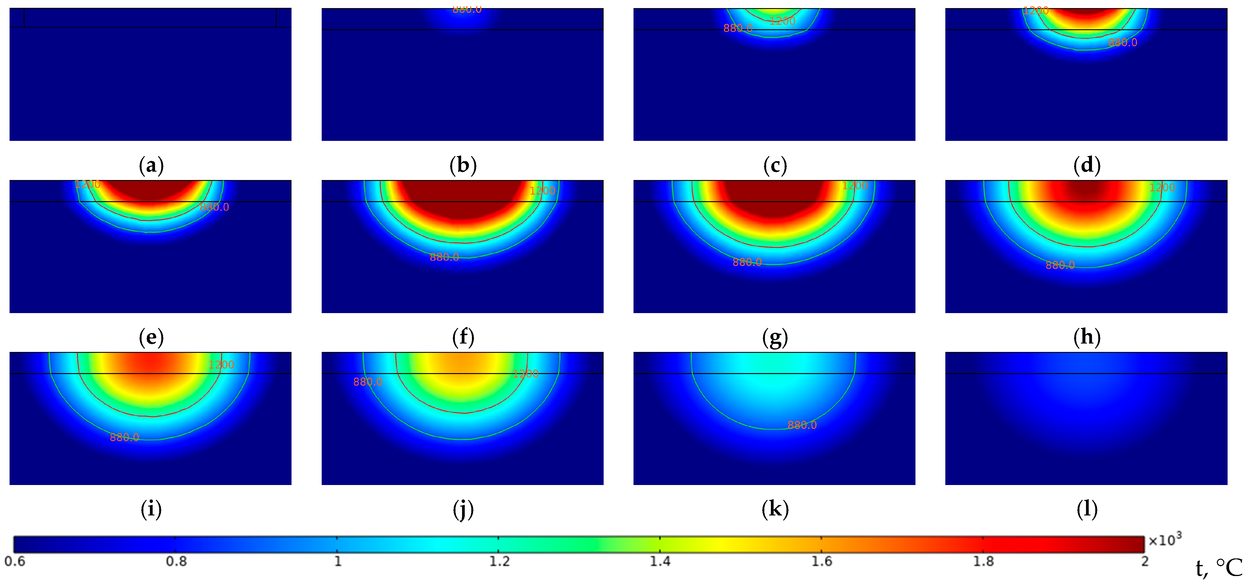
Figure 7, Figure 8 and Figure 9 show the temperature field distributions in the MN19 + VT1-0 bimetal cross-section during laser processing at a power of 1400 W and scanning speeds of 0.8–1.2 m/min. Analysis revealed that, with all other processing parameters constant, increasing the scanning speed decreases the volume of titanium layers heated above 2000 °C and reduces the residence time at peak temperatures. However, the maximum temperatures at peak heating remain virtually unchanged (around 4000 °C).
Figure 7.
Simulation of the heating and cooling process (with a 0.05 s time step) in the MN19 + VT1-0 bimetal cross-section during laser processing at a speed of 0.8 m/min: (a) 0.1 s before heating; (b–f) heating stage; (g–l) cooling stage. The total thermal cycle duration is 0.45 s.
Figure 8.
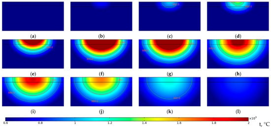
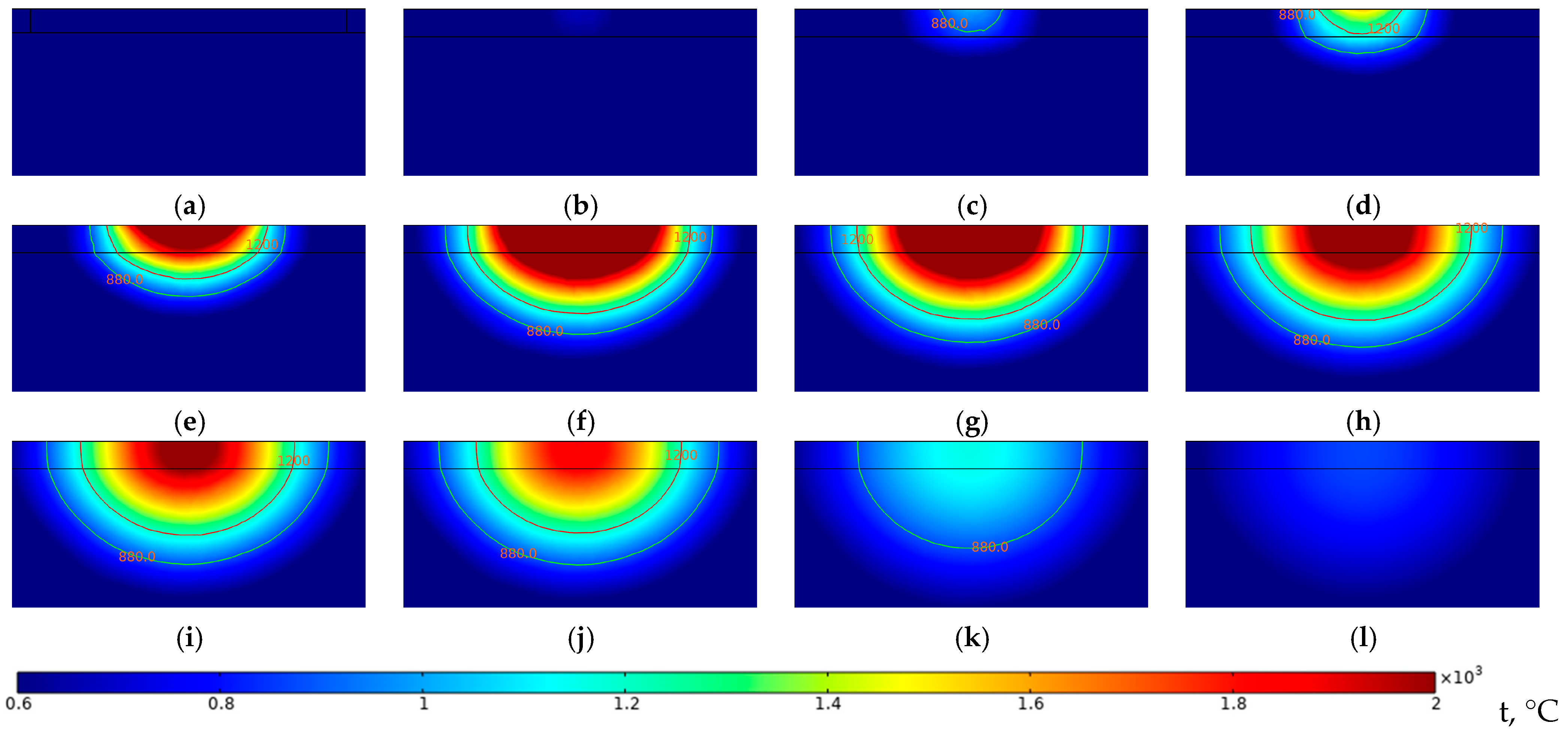
Simulation of the heating and cooling process (with a 0.01–0.03 s time step) in the MN19 + VT1-0 bimetal cross-section during laser processing at a speed of 1.0 m/min: (a) 0.1 s before heating, (b–f) heating stage, (g–l) cooling stage. The total thermal cycle duration is 0.3 s.
Figure 9.
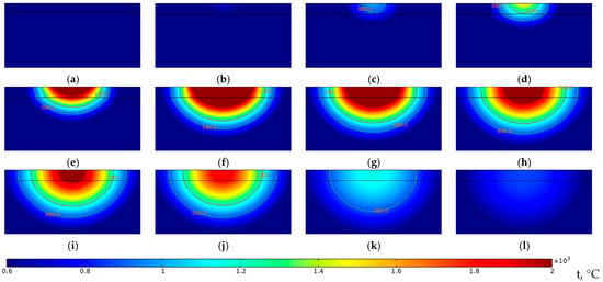
Simulation of the heating and cooling process (with a 0.01 s time step) in the MN19 + VT1-0 bimetal cross-section during laser processing at a speed of 1.2 m/min: (a) 0.1 s before heating, (b–f) heating stage, (g–l) cooling stage. The total heating-cooling cycle time is 0.23 s.
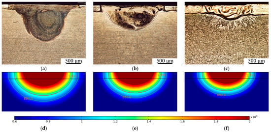
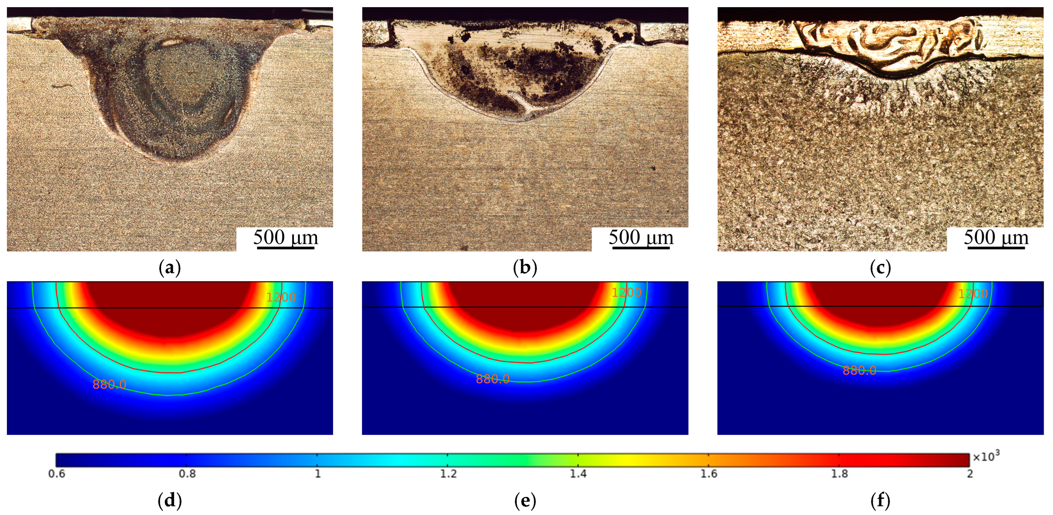
Comparison of the simulation results with experimental data during MN19 + VT1-0 bimetal laser processing at a scanning speed of 0.8–1.2 m/min (Figure 10) revealed the following. The calculated 1200 °C isothermal contour matches the MN19 alloy melting boundary, while the 880 °C isothermal contour during cooling correlates with the grain coarsening zone in the titanium substrate, validating the numerical model (two isothermal contours are shown in the images).
Figure 10.
RMZ structure at V = 0.8 (a); 1.0 (b) and 1.2 m/min (c) and the corresponding distributions of temperature fields at the heating peak (d–f). Spot diameter d = 2 mm. MN19 layer thickness h ≈ 0.3 mm, P = 1400 W.
Figure 7 illustrates the temperature field distribution at a scanning speed of 0.8 m/min. The isothermal contours show the heating of the analyzed cross-section, reaching its peak in Figure 7f. As the laser beam moves further, the peak temperature begins to decline. However, the 1200 °C zone continues to expand for an additional 0.03 s, and the 880 °C zone increases for 0.08 s after the peak temperature is reached. The temperature in the analyzed section drops below 880 °C within 0.45 s from the onset of heating.
Figure 8 and Figure 9 present similar results for scanning speeds of 1.0 and 1.2 m/min, respectively. The peak heating moments are also captured in Figure 8f and Figure 9f. The moments corresponding to the maximum expansion of the 1200 °C and 880 °C thermal zones are shown in Figure 8g,h and Figure 9g,h. It is evident that both the maximum melt pool depth and the heat-affected zone decrease as the scanning speed increases. The total heating–cooling cycle time above 880 °C decreased to 0.30 s and 0.23 s for scanning speeds of 1.0 and 1.2 m/min, respectively.
Increasing the scanning speed leads to a shorter thermal cycle, an increased cooling rate of the melt pool, and the formation of a non-uniform microstructure across the MN19 + VT1-0 bimetal cross-section. Within the studied range, the most uniform remelted zone structure was obtained at scanning speed of 1.0 m/min (Figure 10). The formation of a non-uniform structure at higher speeds may be attributed to insufficient residence time at peak temperatures, which is necessary for the completion of structural transformations.
Due to the difficulty of simultaneously accounting for all laser processing parameters and their effects on the structure and composition of the RMZ, the previously mentioned energy input parameter E was chosen as a single criterion for describing the formation of different types of RMZ. Based on experimental data, laser processing modes were selected so that, with all conditions being equal, the value of E was in the range of 40–55 J/mm2 (by varying P and V). The spot diameter was 2 mm, and the thickness of the copper-nickel alloy layer was ~0.3 mm.
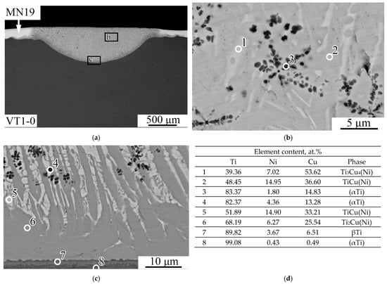
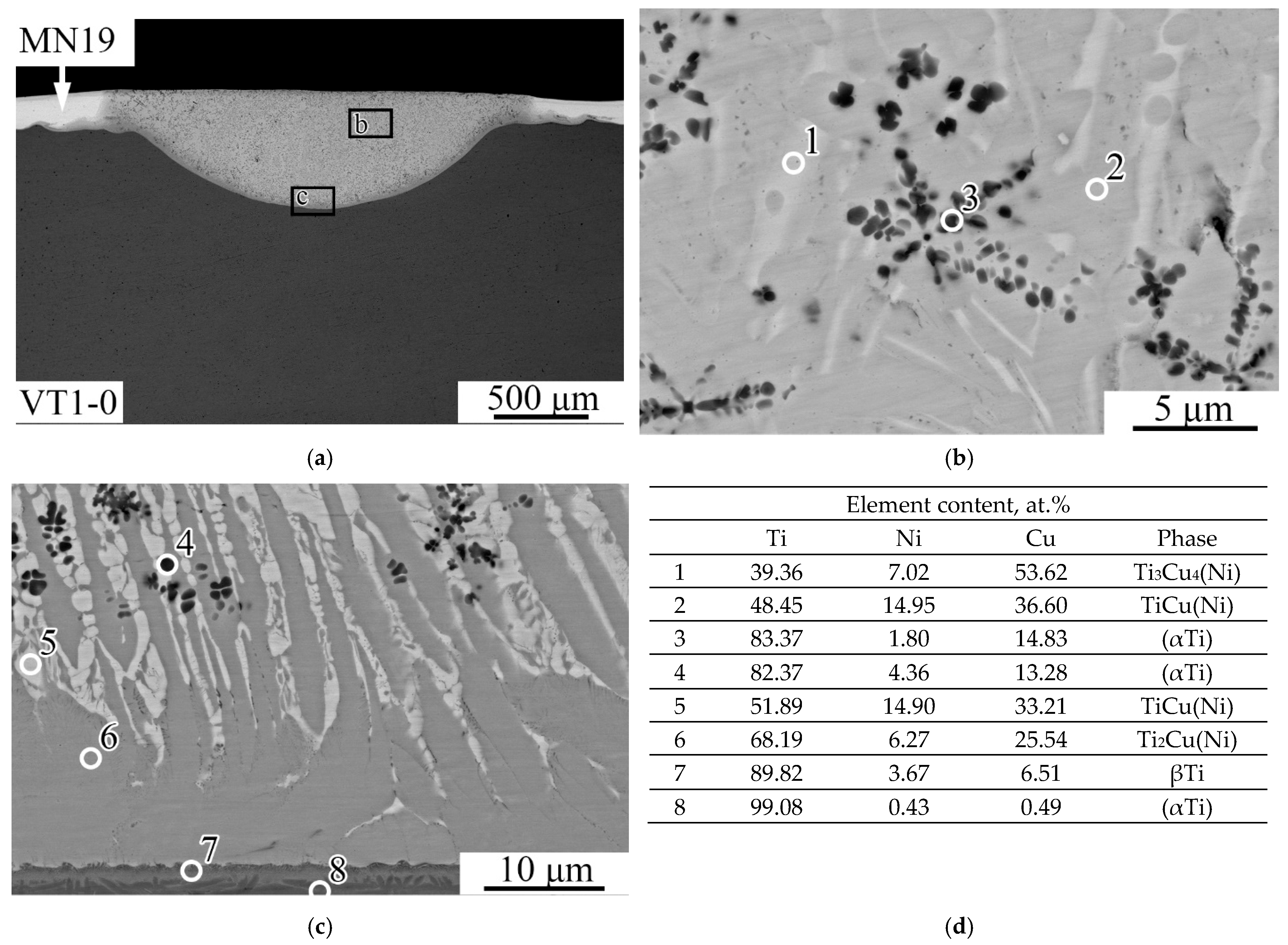
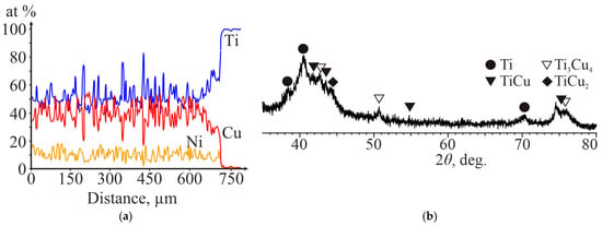
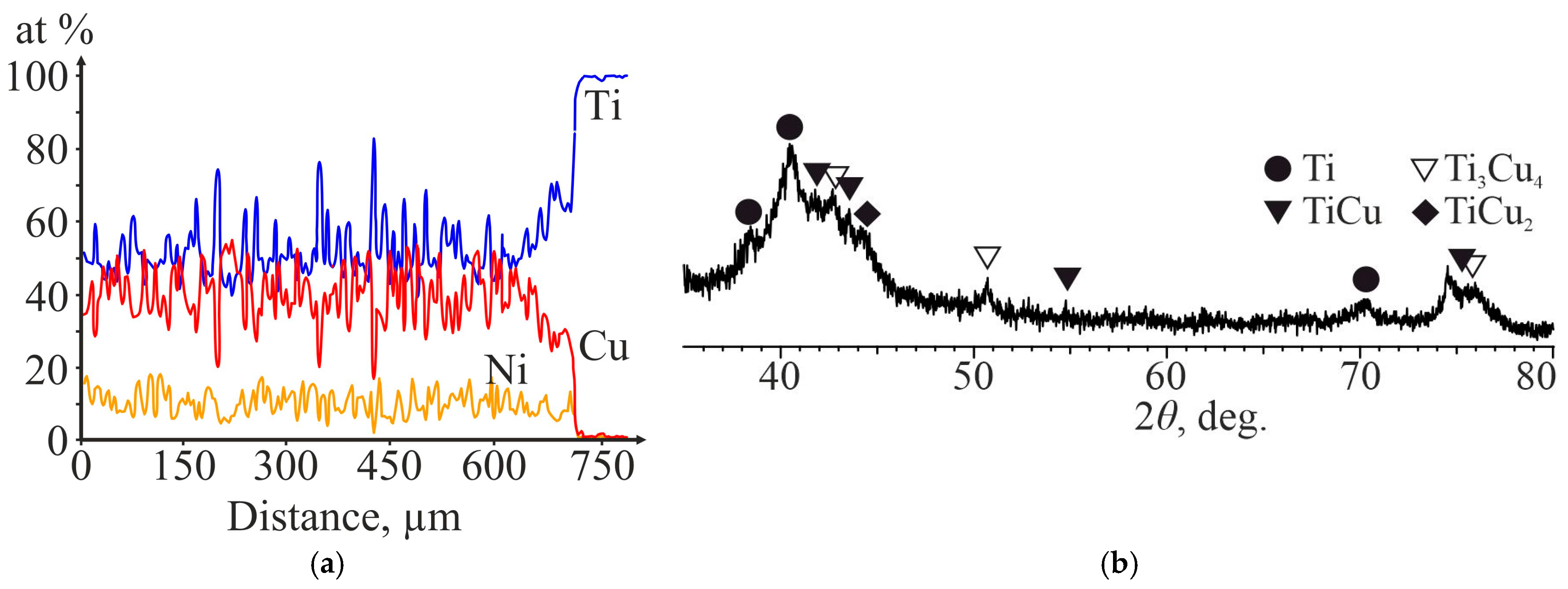
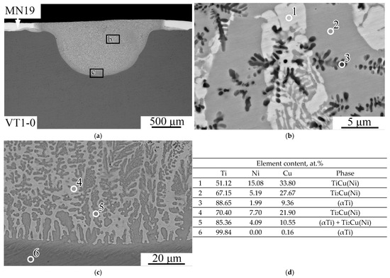
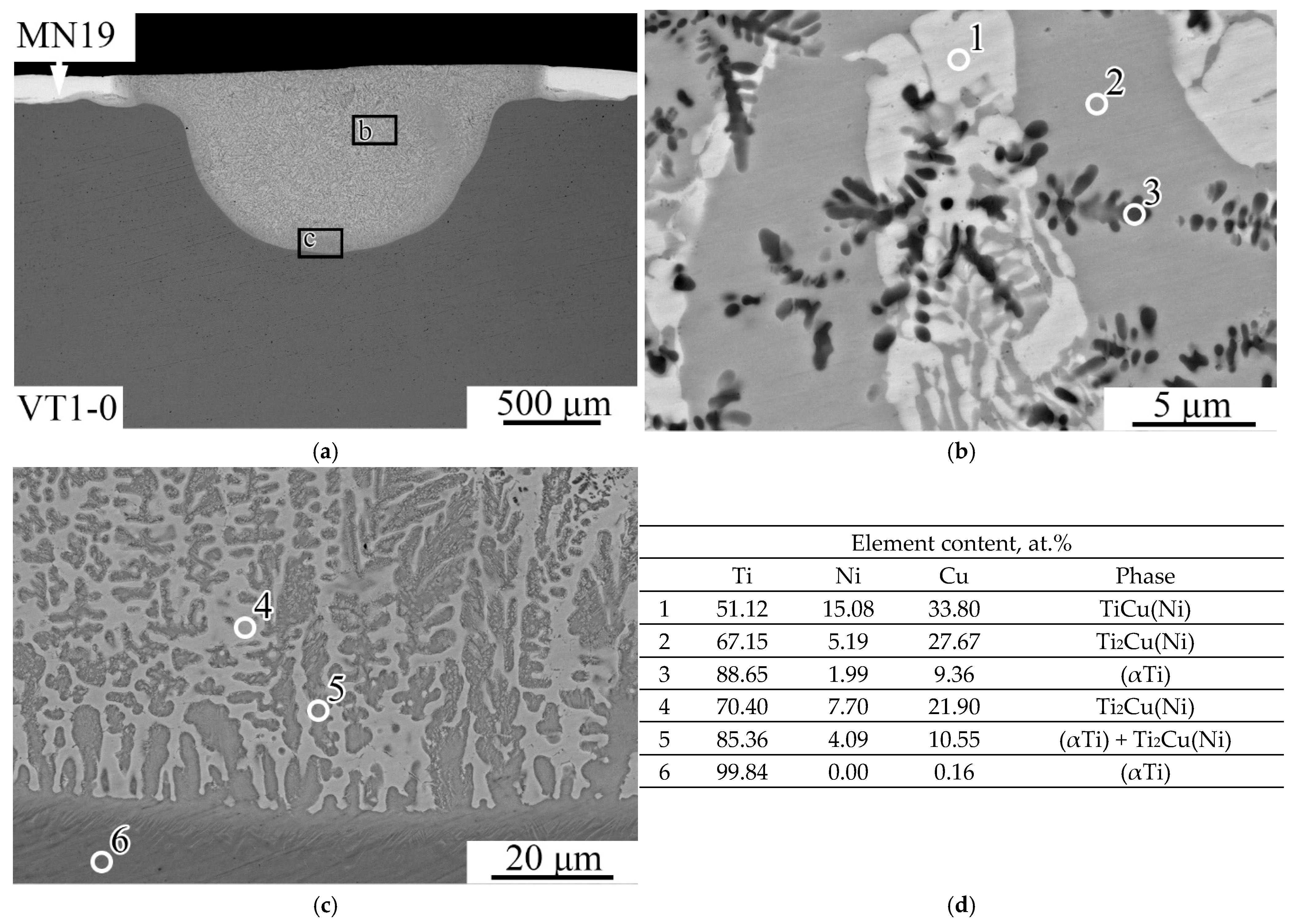
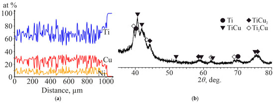
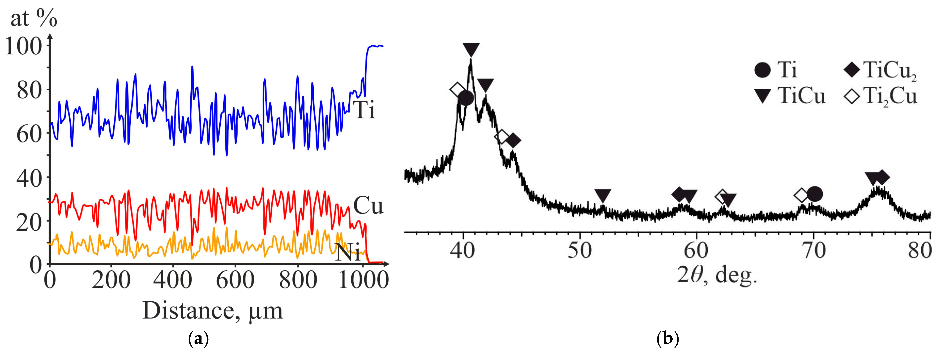
The RMZ structure obtained at P = 900 W and V = 0.5 m/min (E = 54.2 J/mm2) is shown in Figure 11. The maximum titanium penetration depth was ~0.6 mm. Based on a comparison of the EDS and XRD data, the RMZ consists of a finely dispersed mixture of intermetallic phases, including TiCu2(Ni), TiCu(Ni), Ti2Cu(Ni), Ti3Cu4(Ni) with flake-like αTi inclusions (Figure 11 and Figure 12). The low Ti content observed in the latter may be due to their small size (often <1 μm), leading to the contribution of signals from adjacent regions during EDS analysis. The average titanium content across the RMZ cross-section is within ~50 at.% Ti (Figure 12). At the RMZ—titanium interface, a heat-affected zone (HAZ) is observed, comprising a solid-phase diffusion zone and a region with a modified titanium structure. The active formation of the HAZ is attributed to the low thermal conductivity of titanium, occurring through diffusion and mass transfer of alloying elements in the solid phase under the influence of temperature and stress gradients. The primary diffusion channels are grain boundaries and linear defects in the crystalline structure. The solid-phase diffusion zone is approximately 50 μm thick and includes a Ti2Cu(Ni) intermetallic interlayer with acicular TiCu(Ni) inclusions (Figure 11c), adjacent to βTi layer on the titanium side. The formation of the latter is probably due to the formation of quenched structures as a result of accelerated cooling.
Figure 11.
SEM images of the RMZ at the MN19 + VT1-0 joint boundary after laser processing at P = 900 W and V = 0.5 m/min (E = 54.2 J/mm2): (a–c) microstructure and (d) corresponding EDS analysis results.
Figure 12.
Distribution of chemical elements (a) in the cross-section of the RMZ at the MN19 + VT1-0 joint boundary after laser processing at P = 900 W and V = 0.5 m/min (E = 54.2 J/mm2) and the corresponding XRD pattern (b) taken at a depth of 0.3 mm from the RMZ surface.
A simultaneous increase in the laser power and scanning speed to 1200 W and 0.7 m/min (E = 51.3 J/mm2), respectively, leads to an increase in the maximum titanium penetration depth to 0.8 mm. The structure and composition of the RMZ consist of a mixture of intermetallic compounds TiCu(Ni) and Ti2Cu(Ni) with flake-like αTi inclusions. Copper-rich titanium cuprides, such as TiCu2(Ni) and Ti3Cu4(Ni), as well as a continuous βTi zone, were not detected (Figure 13 and Figure 14). The average titanium content in the zone increases to ~65 at.% (Figure 14a).
Figure 13.
SEM images of the RMZ at the MN19 + VT1-0 joint boundary after laser processing at P = 1200 W and V = 0.7 m/min (E = 51.3 J/mm2) (a–c) and corresponding EDS analysis results (d).
Figure 14.
Distribution of chemical elements (a) in the cross-section of the RMZ at the MN19 + VT1-0 joint boundary after laser processing at P = 1200 W and V = 0.7 m/min (E = 51.3 J/mm2) and the corresponding XRD pattern (b) taken at a depth of 0.3 mm from the RMZ surface.
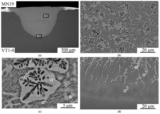
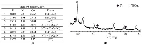
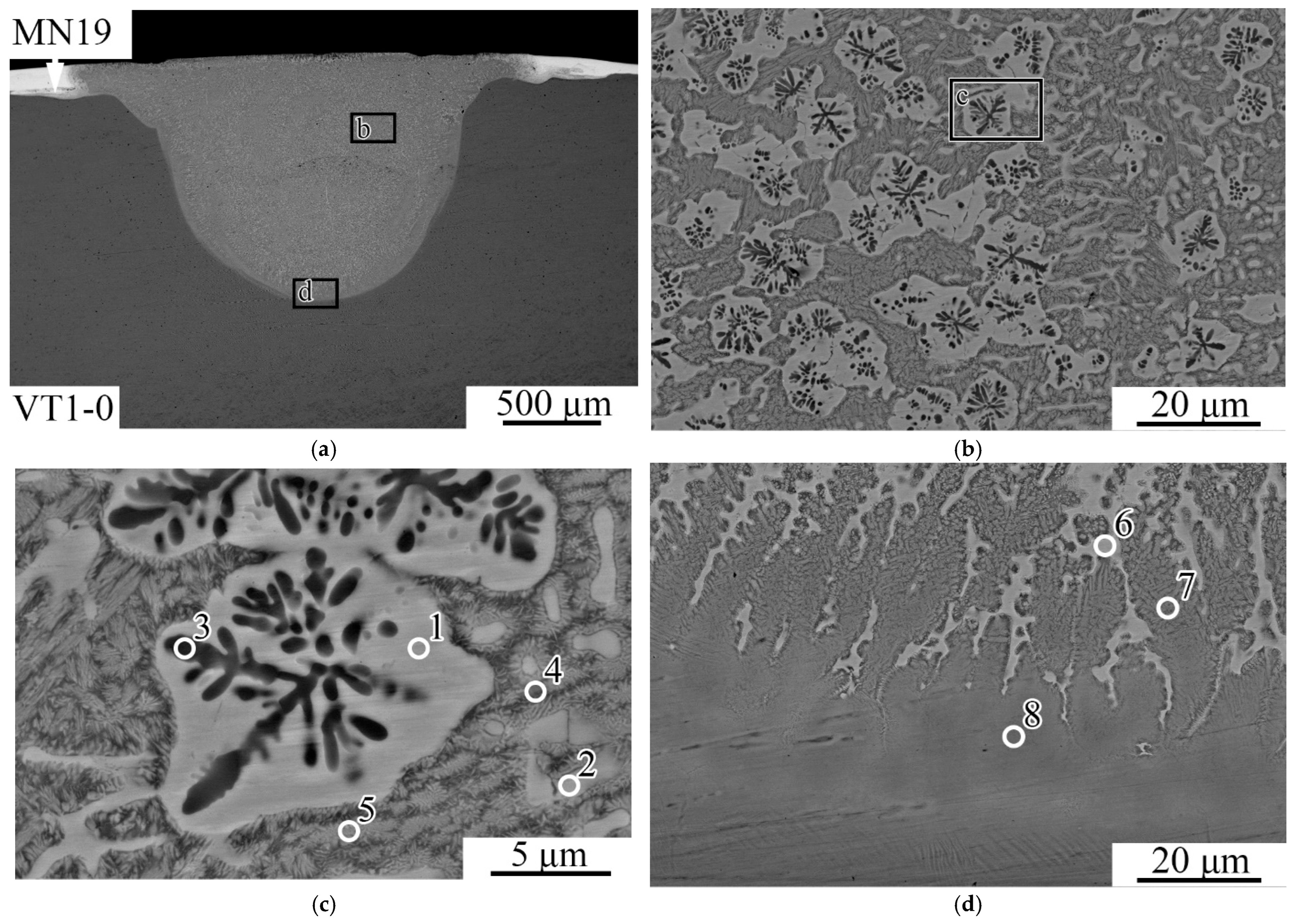
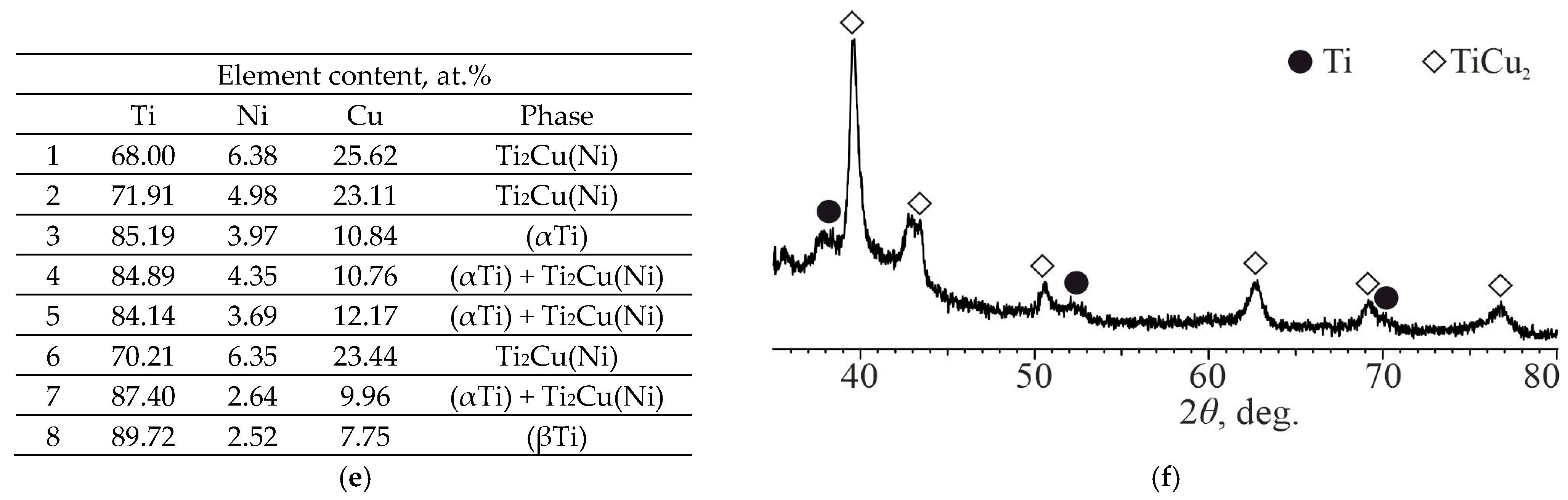
Increasing the laser power to 1400 W and the scanning speed to 0.8 m/min (E = 52.6 J/mm2) resulted in titanium penetration to a depth of ~1.1 mm. The coating structure consisted only of the Ti2Cu(Ni) intermetallic phase and an αTi-based solid solution (Figure 15 and Figure 16). The distribution of chemical elements in the cross-section of the coating was fairly uniform, with an average titanium content of approximately 70 at.% (Figure 15f). The microhardness of the coating ranged from 4 to 5 GPa (±0.2 GPa).
Figure 15.
SEM images of the RMZ at the MN19 + VT1-0 joint boundary after laser processing at P = 1400 W and V = 0.8 m/min (E = 52.6 J/mm2) (a–d) and corresponding EDS analysis results (e,f).
Figure 16.
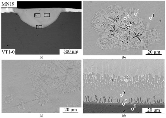
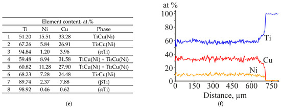
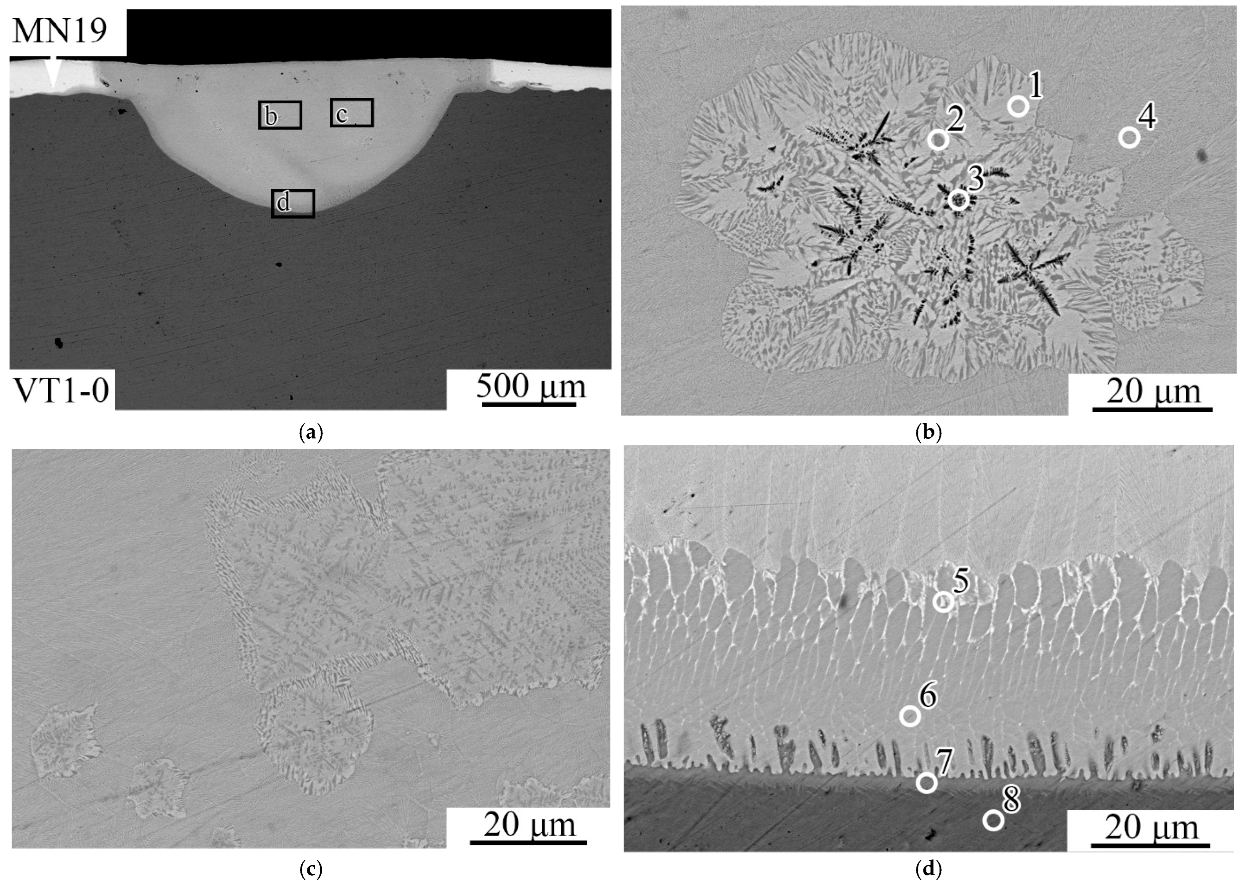
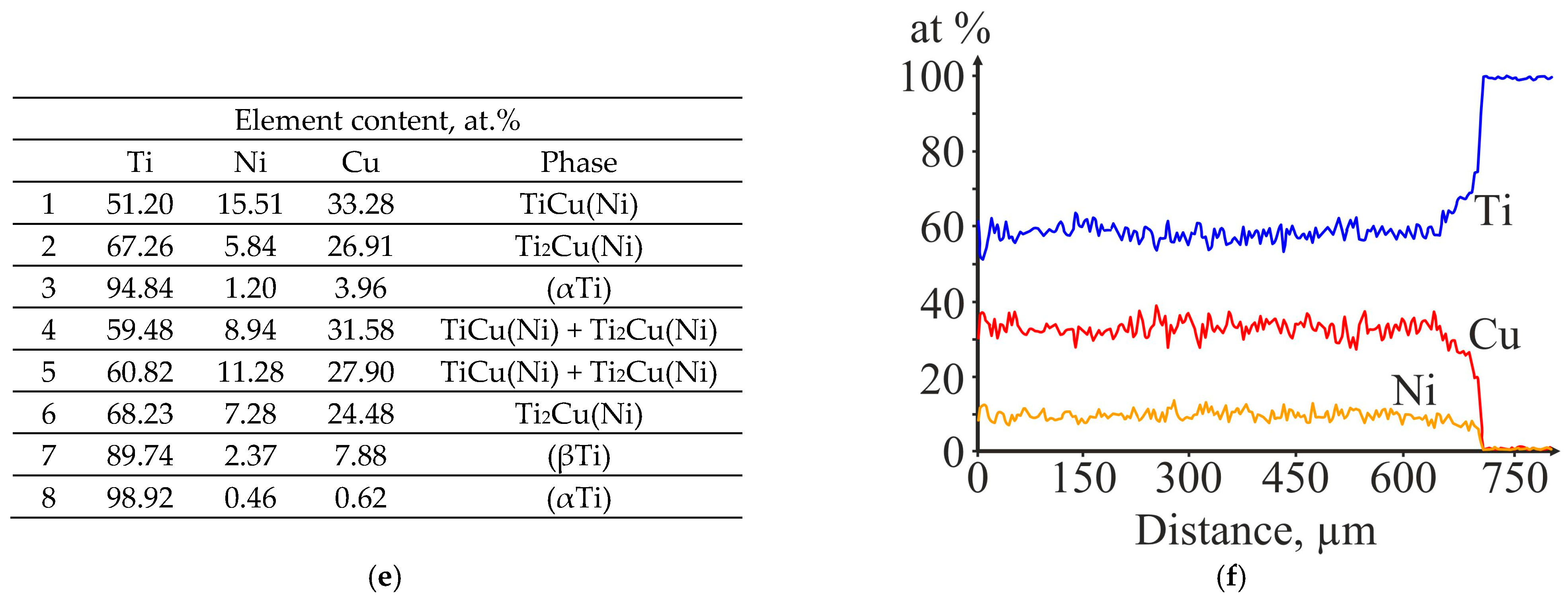
SEM images of the RMZ at the MN19 + VT1-0 joint boundary after laser processing at P = 1400 W and V = 1.0 m/min (E = 42 J/mm2) (a–d) and corresponding EDS analysis results (e,f).
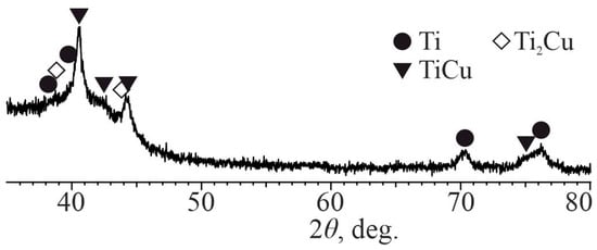
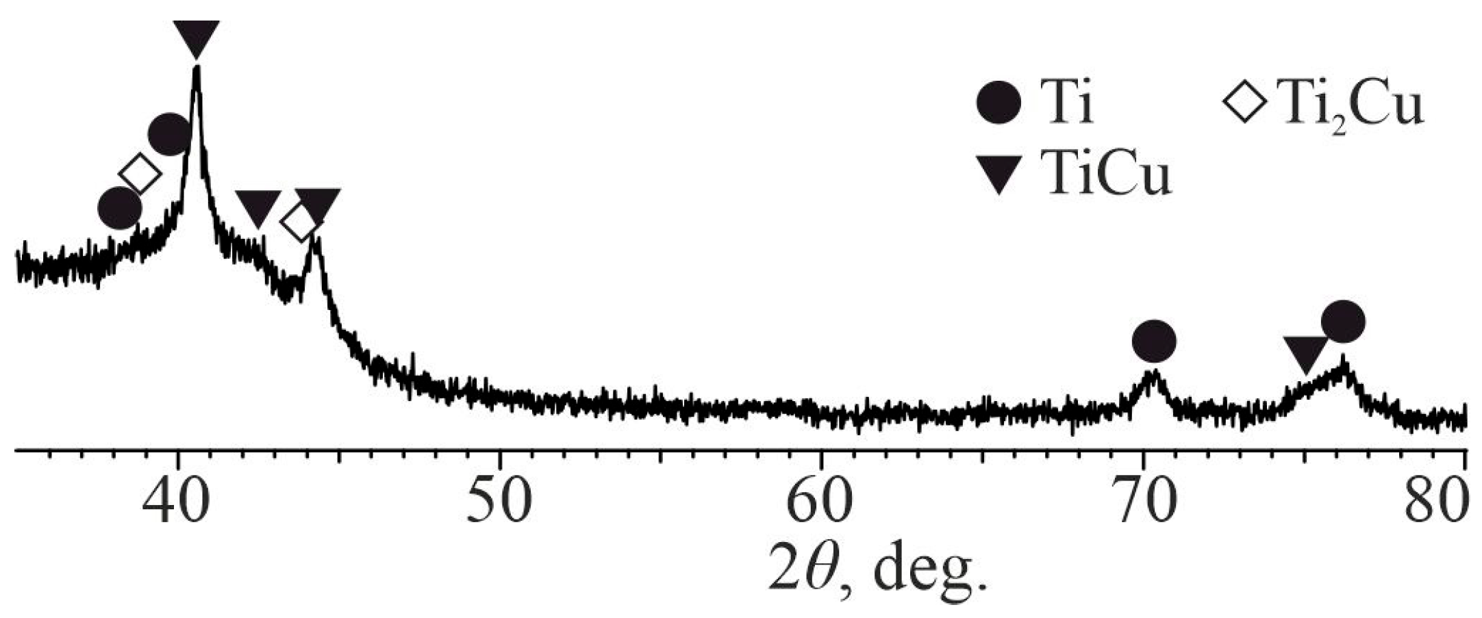
Increasing the scanning speed to 1 m/min (E = 42 J/mm2) at 1400 W made it possible to obtain a finer-grained RMZ structure with a titanium penetration depth of ~0.8 mm (Figure 16). Based on the EDS and XRD data, the RMZ consists of a finely dispersed mixture of the TiCu(Ni), Ti2Cu(Ni) phases (Figure 16 and Figure 17). Precipitations of αTi are practically absent in the RMZ structure. A solid-phase diffusion zone ~50 μm thick is observed, consisting of Ti2Cu(Ni) crystals elongated in the direction of heat dissipation, under which a thin βTi layer is located. This mode ensured the most uniform distribution of Ti, Cu, and Ni at a level of ~60, 30 and 10 at.% (Figure 16f). The average microhardness of the RMZ is 5 ± 0.2 GPa.
Figure 17.
XRD pattern taken at a depth of 0.3 mm from the RMZ surface at the MN19 + VT1-0 joint boundary after laser processing at P = 1400 W and V = 1.0 m/min (E = 42 J/mm2).
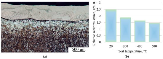
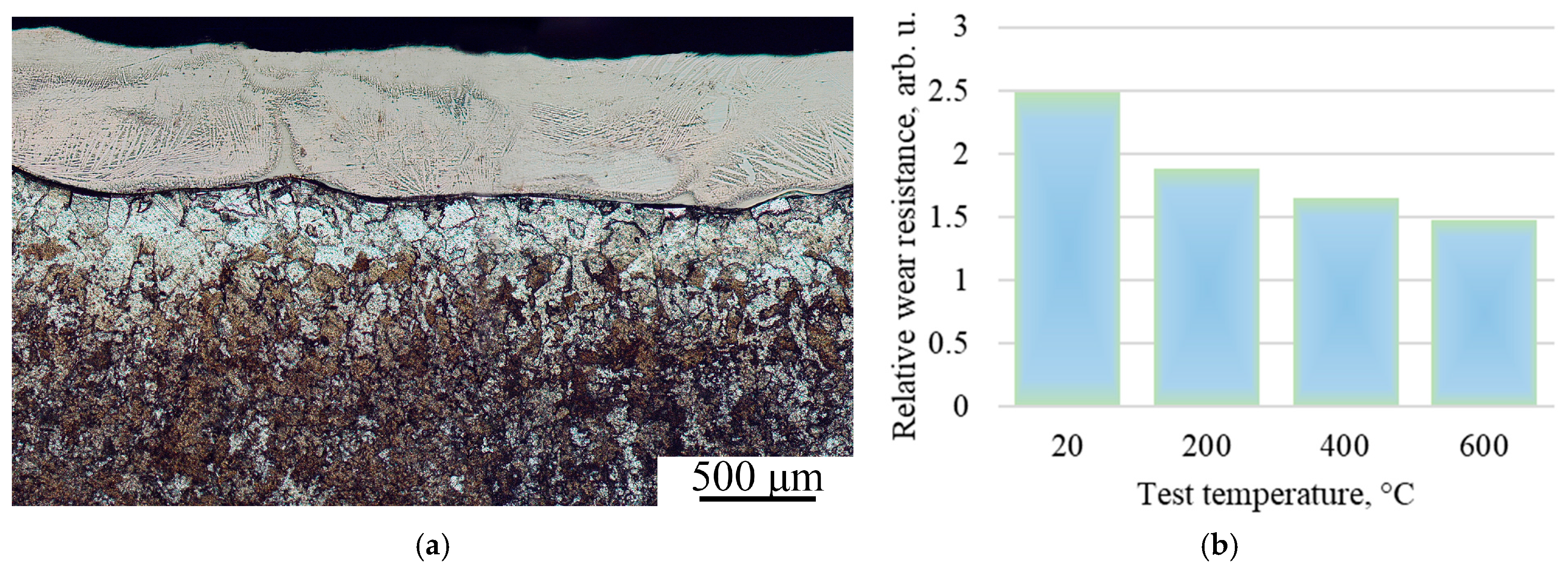
Based on the results of the studies, the following modes were selected to form a continuous coating on the titanium surface (Figure 18a) with a copper-nickel cladding thickness of ~0.3 mm: P = 1400 W, V = 1.0 m/min and d = 2 mm.
Figure 18.
Structure of the Ti-Cu-Ni system coating produced under optimal conditions (a), and its relative wear resistance compared to VT1-0 titanium (b).
Comparative fixed-abrasive wear test (Figure 18b) demonstrated that the Ti–Cu–Ni coatings outperform the base VT1-0 titanium. At room temperature, the 2.5-fold increase in wear resistance is attributed to the formation of a dense, heterogeneous microstructure with a stable microhardness of 5 ± 0.3 GPa, which effectively resists plastic deformation (Figure 18b).
At 600 °C, the coatings maintained 1.5-fold higher wear resistance compared to the substrate (Figure 18b). Since the wear tests were initiated immediately upon reaching the target temperature, any thin oxide film formed during heating was rapidly removed by the abrasive medium. Consequently, the subsequent wear process occurred through direct contact between the coating and the abrasive under steady-state conditions. Therefore, the influence of surface oxidation on the abrasive wear rate can be considered negligible in these specific tests.
The wear resistance values represent the average of three independent measurements. The scatter in the wear data did not exceed 5%, confirming the stability of the coating performance.
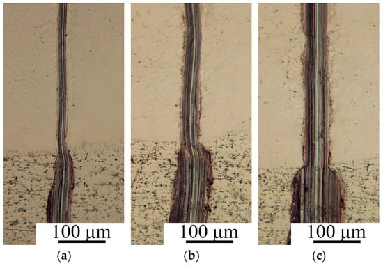
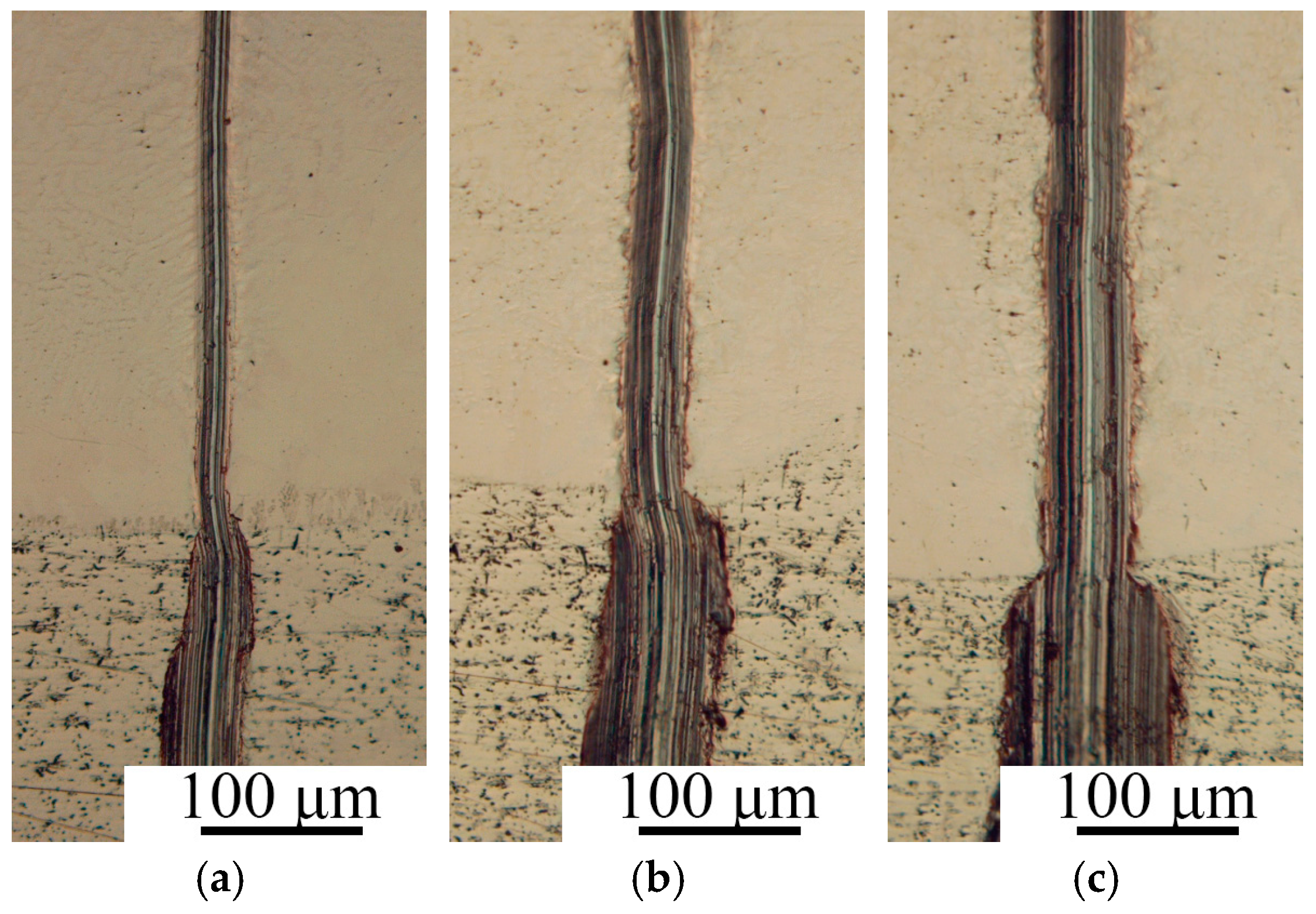
The scratch tests allowed us to evaluate the adhesive and cohesive strength of the coatings (Figure 19). Within the investigated load range up to 5 N, no cracks were observed either at the coating-substrate interface (adhesive cracks) or within the coating itself (cohesive cracks). The absence of cracks suggests sufficient fracture toughness of the Ti–Cu–Ni composite coating. This indicates that the obtained structure and phase composition of the coating effectively limit the formation of cracks, ensuring the mechanical integrity of the Ti–Cu–Ni coating under the test conditions.
Figure 19.
Structure of the Ti-Cu-Ni system coating with micro-scratches applied under a load of 1 (a), 3 (b), and 5 N (c).
The scratch hardness, calculated according to Formula (3), shows minor variations across the coating thickness, ranging from 900 ± 50 MPa at the substrate interface to 1000 ± 50 MPa near the coating surface. The scratch hardness of the titanium substrate did not exceed 220 ± 10 MPa.
4. Conclusions
- It was established that the molten metal, in the form of localized melt pockets, corresponds in composition to the CuNiTi (τ1) ternary intermetallic compound. With a nearly constant Ti content (33–35 at.%), this phase can vary widely in Cu and Ni content. Additionally, presence of Cu3Ti2 and Cu4Ti3 titanium cuprides was confirmed. The microhardness of these melt pockets ranges from 6 to 7 GPa. Furthermore, failure of the specimens during peel testing occurred within the MN19 alloy layer.
- During rolling of the explosively welded MN19 + VT1-0 composite, the wavy interface flattens, while localized melt pockets of the CuNiTi (τ1) intermetallic compound remain undeformed in shape, size, and composition. Low reduction ratios cause non-uniform deformation due to differences in layer properties, but increasing total reduction equalizes layer-by-layer deformation, leading to uniform co-deformation.
- It was established that, within the studied laser parameters, spot diameter critically affects the remelting zone’s width, symmetry, and surface profile. At constant energy density, a 2 mm spot yields a symmetrical zone and smooth surface. At fixed scanning speed, laser power governs penetration depth and titanium content, needing to melt the Cu–Ni cladding without over-penetrating the Ti substrate. Scanning speed inversely controls peak-temperature residence time, dictating microstructure formation. Higher laser power coarsens intermetallic inclusions, while lower power refines them.
- The main structural components of the Ti-Cu-Ni coating (produced by explosive welding, rolling, and laser processing under conditions ensuring a finely dispersed remelting zone) are solid solutions based on the Ti2Cu(Ni) and TiCu(Ni) intermetallics. Deviation from optimal conditions leads to flake-like αTi inclusions in the remelting zone. The fixed-abrasive wear resistance of Ti-Cu-Ni coatings is 2.5 times higher at room temperature and 1.5 times higher at 600 °C compared to VT1-0 titanium. The scratch test results demonstrate high adhesive and cohesive strength of the coating, confirming its mechanical stability and strong bonding with the substrate.
Author Contributions
Conceptualization, L.M.G. and V.G.S.; Methodology, A.I.B. and V.P.K.; Validation, V.P.K. and A.I.B.; Investigation, A.I.B. and V.P.K.; Writing—Original Draft Preparation, A.I.B. and V.P.K.; Writing—Review and Editing, V.G.S.; Visualization, V.P.K. All authors have read and agreed to the published version of the manuscript.
Funding
This work was supported by the Russian Science Foundation (project No. 25-29-20030, https://rscf.ru/en/project/25-29-20030/ (accessed on 1 March 2026)) and by the Volgograd Region Administration.
Data Availability Statement
The original contributions presented in this study are included in the article. Further inquiries can be directed to the corresponding author.
Acknowledgments
Part of this research (electron microscopy and energy dispersive X-Ray spectroscopy) was carried out using the equipment of the Center for Collective Use of the Volgograd State Technical University.
Conflicts of Interest
The authors declare no conflicts of interest.
References
- Gialanella, S.; Malandruccolo, A. Titanium and Titanium Alloys. In Aerospace Alloys; Topics in Mining, Metallurgy and Materials Engineering; Springer International Publishing: Cham, Switzerland, 2020; pp. 129–189. ISBN 978-3-030-24439-2. [Google Scholar]
- Salehi, M.; Hosseini, R. Structural Characterisation of Novel Ti-Cu Intermetallic Coatings. Surf. Eng. 1996, 12, 221–224. [Google Scholar] [CrossRef] [Scilit]
- Akbarpour, M.R.; Moniri Javadhesari, S. Wear Performance of Novel Nanostructured Ti-Cu Intermetallic Alloy as a Potential Material for Biomedical Applications. J. Alloys Compd. 2017, 699, 882–886. [Google Scholar] [CrossRef] [Scilit]
- Jin, X.; Gao, L.; Liu, E.; Yu, F.; Shu, X.; Wang, H. Microstructure, Corrosion and Tribological and Antibacterial Properties of Ti–Cu Coated Stainless Steel. J. Mech. Behav. Biomed. Mater. 2015, 50, 23–32. [Google Scholar] [CrossRef] [Scilit]
- Bateni, M.R.; Ashrafizadeh, F.; Szpunar, J.A.; Drew, R.A.L. Improving the Tribological Behavior of Copper through Novel Ti–Cu Intermetallic Coatings. Wear 2002, 253, 626–639. [Google Scholar] [CrossRef] [Scilit]
- Tian, J.; Xu, K.; Hu, J.; Zhang, S.; Cao, G.; Shao, G. Durable Self-Polishing Antifouling Cu-Ti Coating by a Micron-Scale Cu/Ti Laminated Microstructure Design. J. Mater. Sci. Technol. 2021, 79, 62–74. [Google Scholar] [CrossRef] [Scilit]
- Li, J.; Lei, L.; Du, M.; Zhang, Z.; Zhang, M. Effects of Cu-Ni-Ti Interlayer on Microstructure and Wear Resistance around Gas Tungsten Arc Cladding Copper Matrix Composite Coatings on Steel. Coatings 2022, 12, 1360. [Google Scholar] [CrossRef] [Scilit]
- Wang, S.; Ma, Z.; Liao, Z.; Song, J.; Yang, K.; Liu, W. Study on Improved Tribological Properties by Alloying Copper to CP-Ti and Ti–6Al–4V Alloy. Mater. Sci. Eng. C 2015, 57, 123–132. [Google Scholar] [CrossRef] [Scilit] [PubMed]
- Xu, Y.; Jiang, J.; Yang, Z.; Zhao, Q.; Chen, Y.; Zhao, Y. The Effect of Copper Content on the Mechanical and Tribological Properties of Hypo-, Hyper- and Eutectoid Ti-Cu Alloys. Materials 2020, 13, 3411. [Google Scholar] [CrossRef] [Scilit]
- Chen, Y.; Liu, S.; Zhao, Y.; Liu, Q.; Zhu, L.; Song, X.; Zhang, Y.; Hao, J. Diffusion Behavior and Mechanical Properties of Cu/Ni Coating on TC4 Alloy. Vacuum 2017, 143, 150–157. [Google Scholar] [CrossRef] [Scilit]
- Wang, N.; Chen, Y.-N.; Zhang, L.; Li, Y.; Liu, S.-S.; Zhan, H.-F.; Zhu, L.-X.; Zhu, S.-D.; Zhao, Y.-Q. Isothermal Diffusion Behavior and Surface Performance of Cu/Ni Coating on TC4 Alloy. Materials 2019, 12, 3884. [Google Scholar] [CrossRef] [Scilit]
- Luo, J.; Wang, N.; Zhu, L.; Wu, G.; Li, L.; Yang, M.; Zhang, L.; Chen, Y. Tribological Properties of Ni/Cu/Ni Coating on the Ti-6Al-4V Alloy after Annealing at Various Temperatures. Materials 2020, 13, 847. [Google Scholar] [CrossRef] [Scilit] [PubMed]
- Gu, C.; Wu, Y.; Tian, Z.; Zhao, J.; Wang, Y.; Yuan, M. Effect of Vacuum Heat Treatment on the Microstructure and Tribological Property of Ti–6Al–4V Alloy with Cu Coating. Adv. Eng. Mater. 2023, 25, 2300246. [Google Scholar] [CrossRef] [Scilit]
- Jiang, L.; Cui, X.; Jin, G.; Tian, H.; Tian, Z.; Zhang, X.; Wan, S. Synthesis and Microstructure, Properties Characterization of Ni-Ti-Cu/Cu-Al Functionally Graded Coating on Mg-Li Alloy by Laser Cladding. Appl. Surf. Sci. 2022, 575, 151645. [Google Scholar] [CrossRef] [Scilit]
- Guo, C.; Zhou, J.; Yu, Y.; Wang, L.; Zhou, H.; Chen, J. Microstructure and Tribological Properties of Ti–Cu Intermetallic Compound Coating. Mater. Des. 2012, 36, 482–489. [Google Scholar] [CrossRef] [Scilit]
- Yang, Y.; Cao, S.; Zhang, S.; Xu, C.; Qin, G. Microstructure and Wear Resistance of Ti–Cu–N Composite Coating Prepared via Laser Cladding/Laser Nitriding Technology on Ti–6Al–4V Alloy. Appl. Phys. A 2017, 123, 474. [Google Scholar] [CrossRef] [Scilit]
- Zhu, L.; Liu, Y.; Li, Z.; Zhou, L.; Li, Y.; Xiong, A. Microstructure and Properties of Cu-Ti-Ni Composite Coatings on Gray Cast Iron Fabricated by Laser Cladding. Opt. Laser Technol. 2020, 122, 105879. [Google Scholar] [CrossRef] [Scilit]
- Guchenko, S.A.; Koval, N.N.; Yurov, V.M.; Krysina, O.V.; Laurinas, V.C.; Zavatskaya, O.N. Structure and Properties of Multilayer Plasma Ti-Cu Coatings. Bull. Karaganda Univ. Phys. Ser. 2019, 93, 8–17. [Google Scholar] [CrossRef] [Scilit]
- Andrejeva, D.; Leitans, A.; Urbahs, A.; Savkovs, K.; Urbaha, M. Evaluation of the Friction Coefficient of Antifriction Coatings Based on Ti-Cu Obtained by the Ion-Plasma Deposition in Vacuum. Key Eng. Mater. 2019, 799, 15–19. [Google Scholar] [CrossRef] [Scilit]
- Zhu, Y.; Yan, M.; Zhang, Q.; Wang, Q.; Zhuo, H. Effects of the Prefabricated Cu-Ti Film on the Microstructure and Mechanical Properties of the Multiphase Coating by Thermo Plasma Nitriding on C17200 Cu Alloy. Coatings 2019, 9, 694. [Google Scholar] [CrossRef] [Scilit]
- Adamiak, B.; Wiatrowski, A.; Domaradzki, J.; Kaczmarek, D.; Wojcieszak, D.; Mazur, M. Preparation of Multicomponent Thin Films by Magnetron Co-Sputtering Method: The Cu-Ti Case Study. Vacuum 2019, 161, 419–428. [Google Scholar] [CrossRef] [Scilit]
- Chen, C.; Feng, X.; Shen, Y. Microstructure and Mechanical Properties of Ti–Cu Amorphous Coating Synthesized on Pure Cu Substrate by Mechanical Alloying Method. Rare Met. 2020, 39, 1222–1228. [Google Scholar] [CrossRef] [Scilit]
- Wang, Z.-Q.; Wang, X.-R. Microstructure and Flame-Retardant Properties of Ti-Cu Coating on TC11 Prepared via Electrospark Deposition. In Proceedings of the Material Engineering and Mechanical Engineering; World Scientific: Hangzhou, China, 2016; pp. 1283–1291. [Google Scholar]
- Burkov, A.A.; Chigrin, P.G.; Dvornik, M.I. Electrospark Cu Ti Coatings on Titanium Alloy Ti6Al4V: Corrosion and Wear Properties. Surf. Coat. Technol. 2023, 469, 129796. [Google Scholar] [CrossRef] [Scilit]
- Bogdan, A.; Emil, E.; Jaromír, A. Study of the Effect of Type (Cu, Ti and Cu, Mo) Electrospark Coatings on Friction in Pin-on-Disk Testing. J. Tribol. 2008, 130, 021303. [Google Scholar] [CrossRef] [Scilit]
- Stathokostopoulos, D.; Chaliampalias, D.; Pliatsikas, N.; Kassavetis, S.; Pavlidou, E.; Patsalas, P.; Logothetidis, S.; Chrissafis, K.; Vourlias, G. Ti and nitride surface modification of copper by pack cementation. Surf. Eng. 2018, 34, 243–250. [Google Scholar] [CrossRef] [Scilit]
- Shmorgun, V.; Bogdanov, A.; Kulevich, V.; Taube, A. Experimental Research of the Explosive Welding of Metal Plates with Different Initial Hardness. Mater. Manuf. Process. 2024, 39, 207–216. [Google Scholar] [CrossRef] [Scilit]
- Shmorgun, V.G.; Slautin, O.V.; Kulevich, V.P.; Bogdanov, A.I.; Gurevich, L.M.; Serov, A.G. Influence of Nickel Content on the Formation of an Interaction Zone during Contact Melting of Titanium with Copper-Nickel Alloys. Metals 2024, 14, 298. [Google Scholar] [CrossRef] [Scilit]
- Sarkar, S.K. Lasers in Materials Processing and Synthesis. In Handbook on Synthesis Strategies for Advanced Materials; Tyagi, A.K., Ningthoujam, R.S., Eds.; Indian Institute of Metals Series; Springer Nature: Singapore, 2022; pp. 791–831. ISBN 978-981-16-1802-4. [Google Scholar]
- Buschow, K.H.J. Encyclopedia of Materials: Science and Technology; Elsevier: Amsterdam, The Netherlands; New York, NY, USA, 2001; ISBN 978-0-08-043152-9. [Google Scholar]
- Materials Science International Team MSIT®. Cu-Ni-Ti (Copper—Nickel—Titanium): Light Metal Ternary Systems: Phase Diagrams, Crystallographic and Thermodynamic Data. In Light Metal Systems. Part 4; Effenberg, G., Ilyenko, S., Eds.; Landolt-Börnstein—Group IV Physical Chemistry; Springer: Berlin/Heidelberg, Germany, 2006; Volume 11A4, pp. 1–18. ISBN 978-3-540-25014-2. [Google Scholar]
- Bogdanov, A.I.; Kulevich, V.P.; Shmorgun, V.G. Microstructure Evolution and Growth of Interfacial Intermetallic Compounds in NiCr/Ti Alloy Laminated Composite after Explosive Welding and Heat Treatment. Metals 2023, 13, 1417. [Google Scholar] [CrossRef] [Scilit]
- Fan, Y.; Fan, J.; Wang, C. Formation of Typical Cu–Ti Intermetallic Phases via a Liquid-Solid Reaction Approach. Intermetallics 2019, 113, 106577. [Google Scholar] [CrossRef] [Scilit]
- Jiang, S.; Peng, R.L.; Jia, N.; Zhao, X.; Zuo, L. Microstructural and Textural Evolutions in Multilayered Ti/Cu Composites Processed by Accumulative Roll Bonding. J. Mater. Sci. Technol. 2019, 35, 1165–1174. [Google Scholar] [CrossRef] [Scilit]

Disclaimer/Publisher’s Note: The statements, opinions and data contained in all publications are solely those of the individual author(s) and contributor(s) and not of MDPI and/or the editor(s). MDPI and/or the editor(s) disclaim responsibility for any injury to people or property resulting from any ideas, methods, instructions or products referred to in the content. |
© 2026 by the authors. Licensee MDPI, Basel, Switzerland. This article is an open access article distributed under the terms and conditions of the Creative Commons Attribution (CC BY) license.