


Abstract
Warm forming of heat-treatable aluminium alloys can induce significant changes in their initial heat treatment, affecting both the forming process and the final in-service properties. This work aims to systematically investigate the influence of heat-holding time on the thermo-mechanical behaviour and post-forming properties of Al–Mg–Si alloys (EN AW 6016-T4 and EN AW 6061-T6), with a focus on optimizing process parameters to enhance formability and minimize springback. The study combines uniaxial tensile tests, cylindrical cup forming, hardness measurements, and springback evaluation, at room temperature (RT) and 200 °C, for different heat-holding times. The results show that short heat-holding times improve formability and reduce springback, while longer times promote artificial ageing, increasing strength and hardness but reducing ductility, especially in the EN AW 6016-T4 alloy. The EN AW 6061-T6 alloy exhibits greater thermal stability. The findings provide practical guidelines for industrial warm forming of Al–Mg–Si alloys, highlighting the critical role of heat-holding time in balancing formability, strength, and dimensional accuracy.
1. Introduction
Heat-treatable aluminium alloys are employed in the transportation sector owing to their superior strength-to-weight ratio and good corrosion resistance. Their application is typically for structural and skin components through stamping operations. However, their RT formability is restricted, leading to defects such as premature fracture and springback. Warm forming enhances formability by reducing flow stress, which reduces forming loads and springback [1]. Elevated temperatures promote material softening through increased dislocation mobility and enhanced atomic diffusion [2]. However, in heat-treatable aluminium alloys, warm-forming temperatures overlap with those used for age-hardening treatments, meaning that thermal exposure can trigger precipitation reactions that either harden or soften the material. As a result, careful control of the thermal cycle is required to mitigate undesirable precipitation effects [3]. Particularly, the heat-holding time required to achieve the blank temperature is critical for overall process efficiency [4].
Reviewing the heating methodologies used in research and industrial trials is crucial for the relevance of the present research. The heating technology and procedure used strongly influence the exposure time employed in warm forming [5]. Industry and research applications use hearth furnaces, infrared, induction, resistance, and contact heating. Blanks may be heated either inside or outside the forming tools [1]. External heating risks a 10–20% temperature drop during transfer [6], while in-tool heating requires longer times due to lower heating rates. Additionally, heating behaviour also depends on blank thickness, geometry, emissivity, and electrical resistivity; for aluminium alloys, low emissivity and resistivity result in slower heating rates [7].
Hearth furnaces and infrared systems offer uniform blank temperatures but have low energy efficiency and slow heating rates [7]. Induction and resistance heating provide faster, more efficient heating but may create non-uniform temperature fields, especially for complex geometries [8]. In contact heating, the blank is heated by conduction through contact with preheated tools [9], with heating rate strongly affected by contact pressure and lubrication [10]. Lubrication can increase heat transfer by ~46%, and higher pressures further enhance it. Tool heating typically relies on embedded resistance heaters, though maintaining thermal stability during long cycles remains challenging [9].
In industrial practice, most studies have employed furnaces and contact heating, with typical heating times of about 180 s to reach 200 °C, as reviewed in Billur and Altan [11]. In order to improve production rates, the blanks are often heated outside the forming tools. Morris and George [12] were pioneers in analysing the application of several high-strength aluminium alloys in the T6 condition for automotive parts. The blanks were heated using a portable gas-fired infrared generator to reach 250 °C within 1–2 min (with a black organic coating), followed by transfer to the dies. The optimal forming temperature was approximately 200 °C. Recently, Long et al. [13,14] investigated several 7xxx alloys for lightweight automotive door rings, heating the blanks in a modular furnace. Warm forming was performed at 220–230 °C, improving formability without reducing ultimate tensile strength, for a 90 s cycle. However, increasing the blank temperature to 250 °C for 120 s reduced post-forming strength. A similar approach was successfully applied by Kim [15] to 6xxx and 7xxx alloys for door inner structures.
Applications using contact heating were reported by Grohmann [16] for the serial production of the BMW i8 side-impact door beam using 7075-T6 alloy (2 mm thick). The blank was heated to 200 °C within 60 s in a hydraulic press through direct contact with hot plates. They concluded that short process times are essential to minimize strength loss due to over-ageing. Polak et al. [17] and Gronostajski et al. [18] tested 7075-T6 alloy (3 mm thick) for car brackets and B-pillars, respectively. In these cases, the forming tools were preheated to 240 °C and the blank was placed on them, requiring 20 min to achieve uniform temperature distribution. Finally, Palumbo et al. [19] studied 5754-O alloy (2 mm thick) for railway vehicle components; after 13 min, both tools and blank reached the target temperature of approximately 250 °C.
In prior research studies, several heating strategies have been analysed, with typical heat-holding times of about 10 s up to 40 min to reach 200 °C. Grèze et al. [20] and Panicker et al. [21] used furnace heating, requiring holding times of 30 min and 40 min, respectively, to achieve uniform temperature distribution in the blank; the forming tools and the blank were heated together inside the furnace. Panicker et al. [21] concluded that a preheating time of 40 min was insufficient to induce static strain ageing (SSA) in the 2014-T6 and 6082-T6 alloys. Palumbo et al. [22] studied the hydroforming of an Al–Mg–Si alloy, using heating times of 8 min at 200 °C and 16 min at 250 °C. The greatest improvement in formability was observed at 200 °C, although exposure time to warm-forming temperatures had to be minimized.
Contact heating with heated tools remains the most widely used technology in research trials. Ghosh et al. [23], Kumar et al. [3], and Fan et al. [24] investigated warm forming by contact heating, with total processing times (heating + forming) under 60 s. Ghosh et al. [23] examined 6016-T4 and 6061-T4 alloys at 250 °C, concluding that heat-holding times exceeding 10 min reduce ductility, as the initially soft material (T4 condition) gradually hardens toward T6 properties. Fan et al. [24] reported that Al–Mg–Si alloys achieved enhanced formability and post-forming strength simultaneously at 200 °C. Conversely, Kumar et al. [3] studied the warm forming of a 7020-T6 alloy and noted that post-forming strength decreased by 30% comparing to the as-received material.
Achieving rapid heating with minimal thermal exposure remains challenging in warm-forming operations. Using contact heating, Kumar and Ross [25] were able to externally heat a lubricated blank to 230 °C in approximately 3 s (≈80 °C/s) under a contact pressure of ~0.6 MPa, held for 5 s, and then transferred to the tool; the entire cross-die deep drawing process took about 15 s. Induction heating was investigated by Bariani et al. [26] using a device designed to control heating rate and temperature uniformity for various blank geometries. In their study, a 5083 alloy blank was heated to 250 °C (10 °C/s) in 25 s and held for 90 s for homogenization, after which the inductor head was removed by a pneumatic actuator in 0.2 s. The tools were heated with cartridge heaters to maintain the blank temperature during forming. Resistance heating was applied by Boyer et al. [8] and Royne et al. [27]. Boyer et al. [8] heated a circular 6061-T6 blank to 150 °C in 40 s, ensuring uniform temperature at the centre through sequential activation of three electrode pairs, followed by a homogenization stage. Royne et al. [27]. showed, for a 7075 alloy, that a holding time of less than 10 s at 200 °C for a sheet of 8 mm thickness is required to maintain the T6 state at the end of forming.
Heat-holding time is critical for warm-forming performance and the post-forming mechanical properties of heat-treatable aluminium alloys [4,27]. However, the core focus of most research studies is the analysis of the influence of temperature and strain rate, while the effect of heating time is rarely addressed. Most existing studies predominantly examine temperature and strain-rate effects, overlooking the critical role of thermal exposure duration in microstructural evolution and springback. For instance, Deschamps and Bréchet [28] and Clouet et al. [29] demonstrated that precipitation in Al–Mg–Si alloys is highly sensitive to time and temperature, directly affecting mechanical strength and ductility. Marioara et al. [30] characterised the morphology and distribution of β″ and β′ precipitates as a function of artificial ageing time, while Myhr and Grong [31] modelled the evolution of hardness using time–temperature–property (TTP) diagrams. More recently, Hou et al. [32] and Rao et al. [33] provided quantitative TEM-based data on precipitate size and density during warm forming and post-ageing of 6xxx alloys, reinforcing the importance of controlling thermal exposure to balance formability and final strength. However, few studies have systematically investigated the isolated effect of holding time during warm forming, particularly in relation to the trade-off between enhanced formability and increased springback. This gap is particularly relevant in industrial contexts, where heating and holding times vary significantly depending on the heating technology employed (e.g., furnace, contact, or induction heating) and process conditions. The relationship between holding time and springback—a critical parameter for dimensional accuracy in formed parts—is still not fully understood.
In this context, the present study aims to contribute to a deeper understanding of the role of holding time during warm forming of aluminium alloys (6000 series) by analysing its integrated effects on formability, springback, and post-forming mechanical properties. The experimental approach replicates near-industrial conditions, with holding times ranging from 1 to 30 min at 200 °C, enabling the establishment of practical guidelines for process optimisation. Compared to previous studies that primarily focused on the effects of temperature or strain rate during warm forming of aluminium alloys, the present study provides a more comprehensive understanding of the dual role of holding time—both in shaping the material’s formability and in determining its post-forming mechanical response. This study systematically investigates the influence of holding time under controlled and near-industrial conditions, using two alloys with distinct ageing behaviours (EN AW 6016-T4 and EN AW 6061-T6), and evaluates its impact on tensile strength, hardness, and springback. By combining mechanical testing, microhardness profiling, and springback analysis, this study offers new insights into how thermal exposure time can be optimised to balance formability and dimensional accuracy without compromising final part performance.
2. Materials and Methods
2.1. Materials
The thicknesses and mechanical properties at RT of the aluminium alloys tested are presented in Table 1. The alloy EN AW 6016-T4 is prone to natural ageing, which occurs mainly within the first seven months after solution heat treatment (SHT). The alloy EN AW 6061-T6 undergoes artificial ageing after SHT to achieve peak strength. Consequently, EN AW 6016-T4 exhibits a more ductile behaviour, whereas EN AW 6061-T6 is comparatively brittle due to the different heat treatments.
Table 1.
Mechanical properties of EN AW 6016-T4 and EN AW 6061-T6 alloys at RT 1.
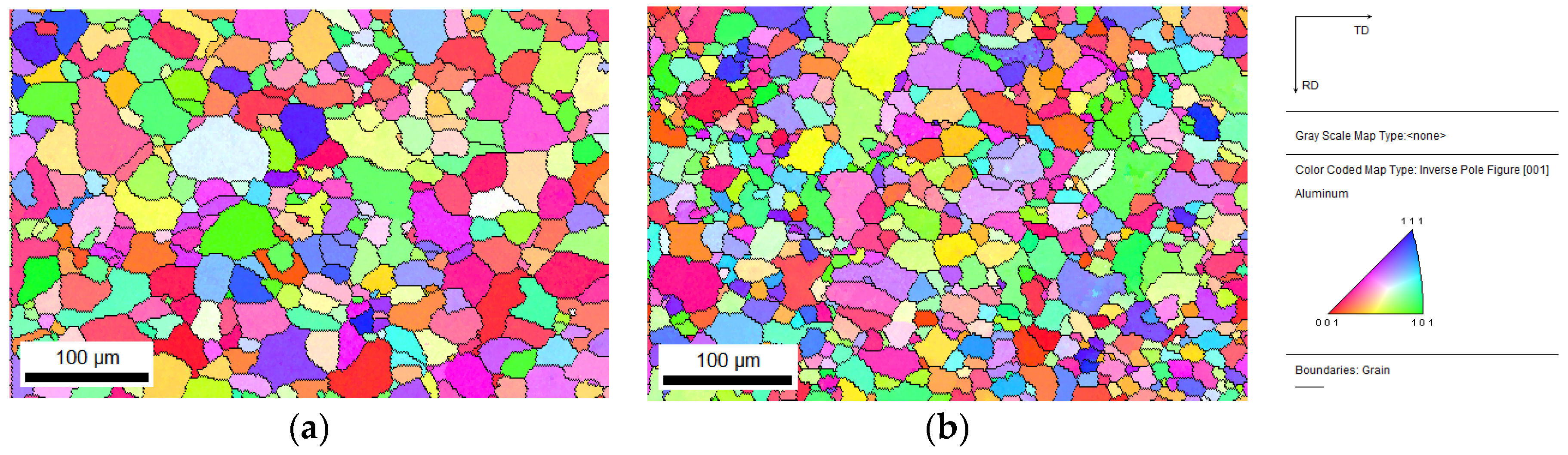
The microstructural characterization of the as-received materials was carried out using scanning electron microscopy (SEM; Quanta 200 ESEM-FEG; FEI Company, Hillsboro, OR, USA)) coupled with electron backscatter diffraction (EBSD, EDAX/TSL EBSD system (EDAX Inc., Draper, UT, USA), operated with the OIM Analysis software (EDAX Inc., Draper, UT, USA)). Each EBSD map typically comprises 200–400 grains. The EBSD measurements shown in Figure 1 were performed on the plane of the sheet, i.e., the RD–TD plane (RD: rolling direction; TD: transverse direction), which is perpendicular to the normal direction (ND).
Figure 1.
Grain microstructure with EBSD1 analysis: (a) EN AW 6016-T4, (b) EN AW 6061-T6. 1 The sample’s surface for the EBSD analyses was prepared by grinding to 1000, 2400, and 4000 grit silicon carbide papers, followed by cloth polishing in 1 and ¼ µm diamond suspension.
The EN AW-6016-T4 alloy exhibits an equiaxed grain structure with an average grain diameter of approximately 32 µm and a standard deviation of 12 µm. The EN AW-6061-T6 alloy also presents equiaxed grains, with an average grain diameter of approximately 23 µm and a standard deviation of 14 µm.
2.2. Overview of the Al–Mg–Si Alloys Microstructure
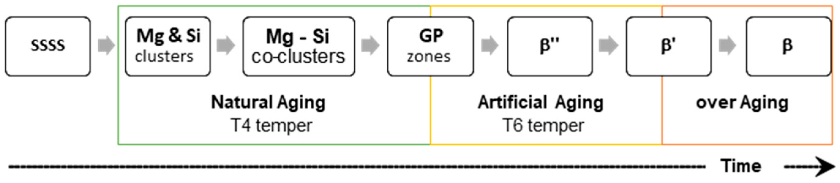
In heat-treatable Al–Mg–Si alloys, the temperature range for warm forming overlaps with that for artificial ageing. The time required for warm forming (heat-holding time) can induce changes in the heat treatment, thereby altering the thermo-mechanical behaviour. Understanding the precipitation sequence of Al–Mg–Si alloys is essential to assess the influence of heat-holding time on their thermo-mechanical response. The precipitation sequence illustrated in Figure 2 is based on standard models widely reported in the literature, such as those described by Buha et al. [35].
Figure 2.
Conceptual, qualitative sequence of precipitation in Al–Mg–Si alloys during T4 and T6 ageing, highlighting the dominant stages typically discussed in the literature.
After heat treatment at approximately 500 °C, which dissolves Mg and Si atoms in the aluminium matrix, the material is rapidly quenched to RT, promoting a supersaturated solid solution (SSSS). In this state, Al–Mg–Si alloys are unstable and prone to precipitation, which can occur either by natural ageing at RT or by artificial ageing at elevated temperatures between 170 °C and 200 °C. Precipitation is a diffusion-controlled phenomenon strongly dependent on time and temperature.
In the natural ageing T4 condition, precipitation involves the formation of small spherical Mg–Si clusters that are coherent with the aluminium matrix. The strength in the T4 condition results from lattice distortion. During subsequent artificial ageing, these clusters dissolve and form larger precipitates. The T6 heat treatment produces needle-shaped β″ precipitates, which are semi-coherent with the aluminium matrix and provide maximum strength. Prolonged exposure at warm temperatures (artificial ageing) leads to over-ageing, where β″ precipitates grow into coarse, non-coherent particles, causing a reduction in strength. Finally, as precipitation progresses, the kinetics slow down, and the alloy becomes thermally more stable [36].
2.3. Experimental Procedure
Experimental tests were carried out at room temperature (RT, ≈22 °C) and at 200 °C. The room-temperature tests were used as a reference, whereas the temperature of 200 °C was selected based on data from the literature for Al–Mg–Si alloys, as it enhances formability without compromising post-forming mechanical properties [24,37]. At 200 °C, heat-holding times of 1, 10, and 30 min were investigated. The thermomechanical material behaviour was assessed through uniaxial tensile tests and warm forming of cylindrical cups. Post-forming characterization included the measurement of cup dimensions, the evaluation of hardness evolution along the cup wall, and the assessment of springback using the split-ring test.
In addition, for the EN AW-6016-T4 alloy, tensile tests were performed after 1 and 7 months of natural ageing, while cylindrical cup tests were conducted after 1 and 18 months. The mechanical behaviour of this alloy is similar for natural ageing times of 7 and 18 months [38].
2.3.1. Tensile Tests
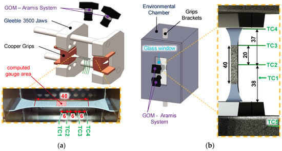
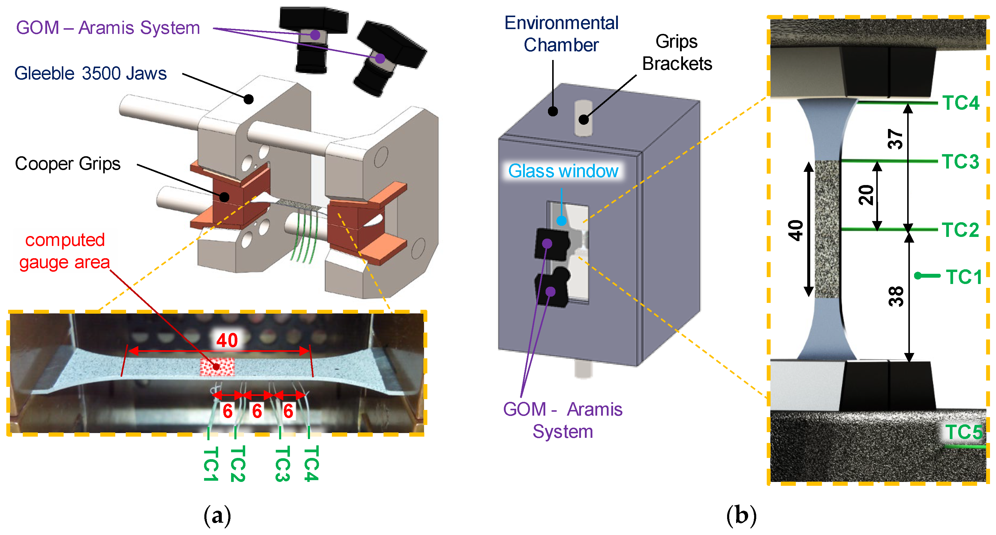
Uniaxial tensile tests were carried out using a Gleeble 3500 thermomechanical simulator (Dynamic Systems Inc., Poestenkill, NY, USA) and an Instron 4505 universal testing machine equipped with an environmental chamber (Instron Corporation, Norwood, MA, USA). Figure 3 presents the two tensile test configurations. The Gleeble 3500 system was used for tests with a heat-holding time of 1 min, whereas the environmental-chamber setup was employed for heat-holding times of 10 and 30 min. Strain fields were measured using a digital image correlation (DIC) system (ARAMIS 4M, GOM mbH, Braunschweig, Germany).
Figure 3.
Illustration of tensile tests devices: (a) the Gleeble 3500 device, with the ARAMIS system positioned above (top); (b) the environmental chamber coupled with an Instron 4505 tensile test machine, with the Aramis system positioned outside the environmental chamber.
Temperature monitoring was performed using K-type thermocouples (chromel–alumel, wire diameter 250 µm) welded to the specimen surface. The thermocouples were positioned along the gauge length—at the centre and at both ends—in accordance with ISO 6892-2 [39]. All tests were conducted under displacement control with a prescribed crosshead speed of 0.1 mm/s, corresponding to an initial strain rate of 2 × 10⁻³ s−1. The gauge section had a length of 40 mm and a width of 10 mm. Specimens were cut from the as-received sheets along the rolling direction (RD) using electrical discharge machining (EDM) to ensure dimensional accuracy and appropriate surface finish.
A minimum of three tests were performed for each condition. Reproducibility was confirmed by the low scatter in true stress, which remained below ±1 MPa at the same true strain; therefore, only one representative test is presented for each condition.
Figure 3a shows a schematic of the Gleeble device with its main components. The ARAMIS system was positioned above the Gleeble jaws, with cameras focused on the specimen surface. The Gleeble system allows a rapid heating rate of 10 °C/s, reaching 200 °C within 20 s. However, this heating method induces a temperature gradient along the specimen length, with the highest temperature occurring at the centre due to 50 Hz AC ohmic heating. Temperature was controlled in a closed loop via thermocouple TC1 at the specimen centre. Strain measurements were taken from a central gauge area (3 mm × 6 mm), ensuring a temperature gradient below 1 °C. Figure 3b shows the environmental chamber coupled to the Instron 4505 machine. The ARAMIS system was positioned outside the chamber, with cameras viewing the specimen through a double-glass window. Heating was achieved by forced convection, circulating hot air around the grips and specimen. The heating rate exhibited two slopes: 15 °C/s from RT to 150 °C, and 0.7 °C/s from 150 °C to 200 °C. Although the specimen reached 200 °C within 100 s, additional holding time was required for thermal stabilization and ARAMIS setup. This method ensures minimal thermal gradients and good stability but results in longer heat-holding times. To reduce this, the chamber and grips were preheated to 200 °C for 1 h. The tensile test began after 10 min or 30 min of holding time once the specimen was placed on the heated grips.
2.3.2. Warm Forming Tests
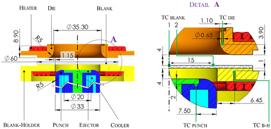
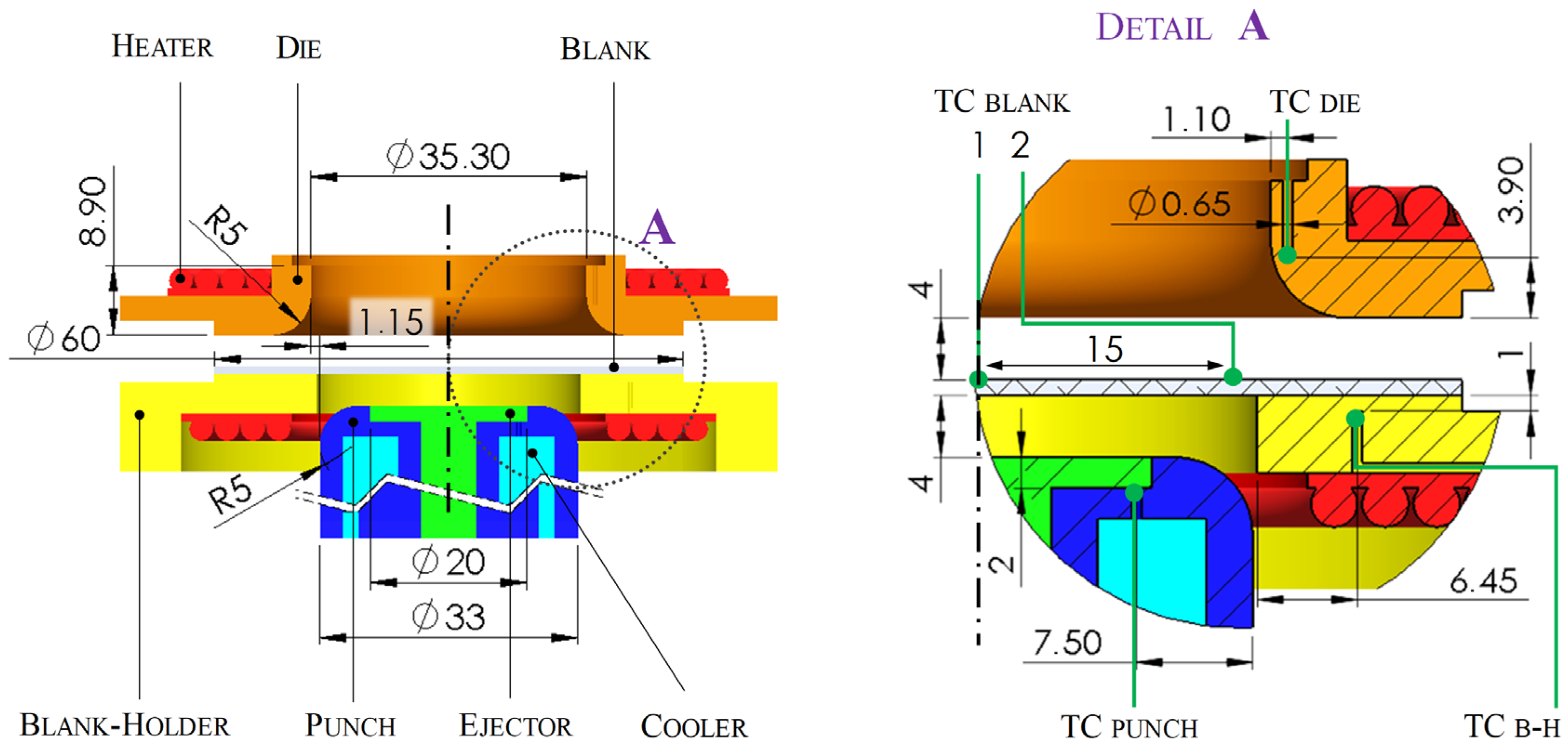
The warm-forming tests consisted of shaping a flat metal sheet (blank) into a cylindrical cup. Figure 4 shows a schematic of the device and tool dimensions. The setup comprises three main components: die, blank holder, and punch. All tools are axisymmetric, and their dimensions comply with ISO 11531 [40] (Earing test), resulting in a drawing ratio of β = 1.8. The machine used was a msler BUP200 sheet metal testing system (ZwickRoell GmbH & Co. KG, Ulm, Germany), adapted with specific tools for warm forming.
Figure 4.
Tools dimensions (in mm), showing the position of the thermocouples.
Heating of the die and blank holder was achieved using electrical resistance heating rods integrated into the tools, while the punch was cooled by a water-circulation system to maintain its temperature near RT. The sheet was always heated inside the tools to avoid temperature drops associated with transfer. Temperature was measured using type-K thermocouples: 50 µm wires for the tools and 250 µm wires for the blank. Thermocouples were positioned as follows: (i) die radius (TC Die); (ii) punch (TC Punch); and (iii) blank holder at the flange zone (TC B-H). On the blank, sensors were placed at the centre (TC Blank 1) and 15 mm from the centre (limit of the punch radius) (TC Blank 2). The temperature measurement accuracy was ±0.5 °C.
The cylindrical cup test procedure consisted of the following steps: (i) the blank was lubricated using a grease lubricant (Jelt Grease 5411, aerosol, kinematic viscosity 95 cSt; JELT SAS, Chartres, France) and positioned on the die; (ii) the blank holder pressed the blank against the die with a force of 6 kN, which remained constant throughout the subsequent steps; (iii) the punch moved vertically, forcing the blank into the die cavity at a constant speed of 1.1 mm/s, resulting in a strain rate of up to 2 × 10⁻² s−1 [41]; and (iv) the ejector (located inside the punch) was activated to remove the cup from the die cavity.
During each test, the following parameters were recorded: punch and blank-holder forces, punch displacement, and temperature of the tools and blank. A minimum of four reproducible tests were performed for each condition. Reproducibility was confirmed by the scatter in punch force, which was less than ±0.1 kN for the same displacement; therefore, only one representative test is presented for each condition.
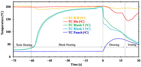
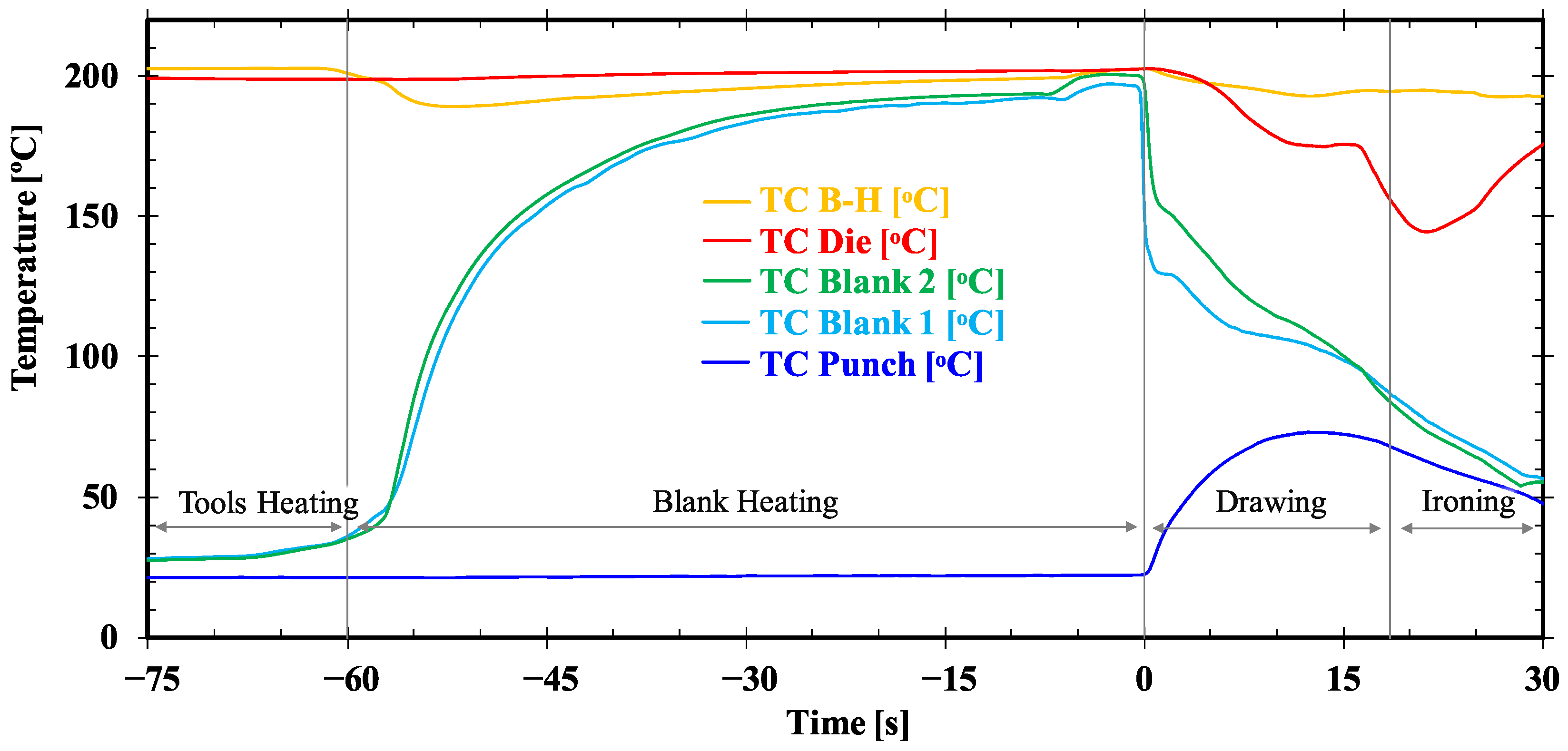
The temperature evolution as a function of time for a cylindrical cup test performed at 200 °C, with a heat-holding time of 1 min, is presented in Figure 5. Figure 5 highlights the temperature evolution during the heating, holding, and forming stages (drawing and ironing). The results correspond to the EN AW 6016-T4 alloy (aged for one month). However, the temperature evolution curves are similar for all tests performed on both aluminium alloys. In effect, a longer holding time only affects the temperature during that stage and does not alter the shape of the curves during the forming stage.
Figure 5.
Temperature evolution during warm forming of a cylindrical cup test at 200 °C using EN AW 6016-T4, performed with a preheated die and blank holder and a cooled punch. Negative time refers to the 1 min heat-holding stage, while positive time corresponds to the forming stage. This test procedure is shown in Video S1.
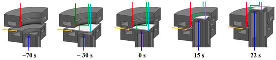
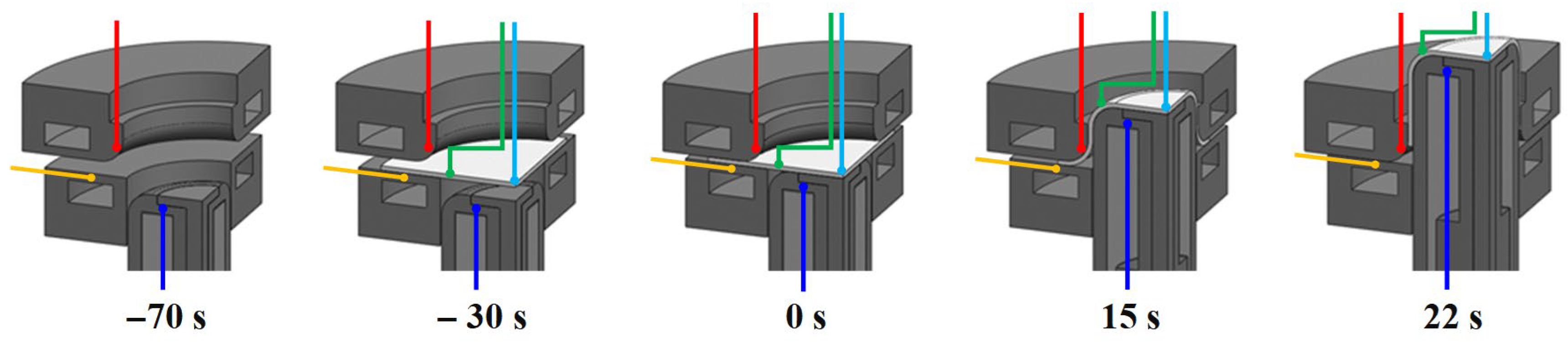
In Figure 5, negative time denotes the heat-holding stage, while positive time corresponds to the forming stage. A schematic illustration of the warm-forming procedure is shown in Figure 6, highlighting the sequence of stages shown in Figure 5 as well as the thermocouple locations. The heat-holding stage comprises two steps: (i) preheating the die and blank holder, and (ii) heating and stabilizing the blank temperature. Preheating the tools reduces the blank heating time. Once placed on the blank holder, the blank requires approximately 60 s to reach the test temperature. Throughout this period, the punch is actively cooled to maintain a low temperature (close to RT). The temperature at the blank centre (TC Blank 1) is slightly lower than that at the flange zone (TC Blank 2), as a small amount of convective heat transfer occurs between the blank centre and the punch, although the punch remains 4 mm away from the blank.
Figure 6.
Schematic illustration of warm forming of a cylindrical cup according to the stages shown in Figure 5, highlighting the thermocouple positions with coloured arrows.
The forming operation consists of a drawing stage followed by an ironing phase. Drawing begins at time zero, when the punch first contacts the blank. This initial contact causes an abrupt drop in the blank temperature as thermal equilibrium begins to establish between the tools and the sheet. At this moment, TC Blank 1 records a lower temperature than TC Blank 2 because the blank centre comes into contact with the cooled punch first. As the punch advances into the die cavity, the drawing phase progresses. During this stage, the blank gradually increases its contact area with both the cooled punch (bottom and radius) and the heated die radius. This interaction increases the punch temperature while reducing that of the die, as illustrated in Figure 5 at 15 s. Heat is conducted from the flange zone through the blank and dissipated via the punch cooling system, leading to a near-linear decrease in the blank temperature.
The ironing phase begins at approximately 18.5 s. This stage occurs because the local blank thickness exceeds the die–punch gap (1.15 mm). During drawing, circumferential compression in the flange induces material thickening. To enable material flow through the restricted gap, the blank undergoes substantial through-thickness compression combined with axial stretching. These conditions generate high contact pressures, deform asperities at the tool–sheet interface, increase the real contact area, and reduce the thermal contact resistance. Consequently, the interfacial heat-transfer coefficient increases [42], contributing to the temperature drop observed in the die radius during ironing. After approximately 22 s, the contact area between the blank and the die decreases. As a result, the die temperature rises back toward 200 °C, while the temperatures of the punch and the sheet continue to decrease nearly linearly to about 50 °C, as shown in Figure 5.
2.3.3. Post-Forming Analysis: Cup Dimensions, Hardness, Springback
The cup dimensions, hardness, and springback were evaluated after the forming operation. For each test condition, only one representative result is presented. All formed cups were measured for dimensional analysis, as this procedure is non-destructive and the cup specimens can subsequently be used for hardness and springback evaluation. For the hardness and springback assessments, two cylindrical cup specimens were examined for each test condition.
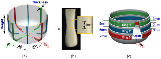
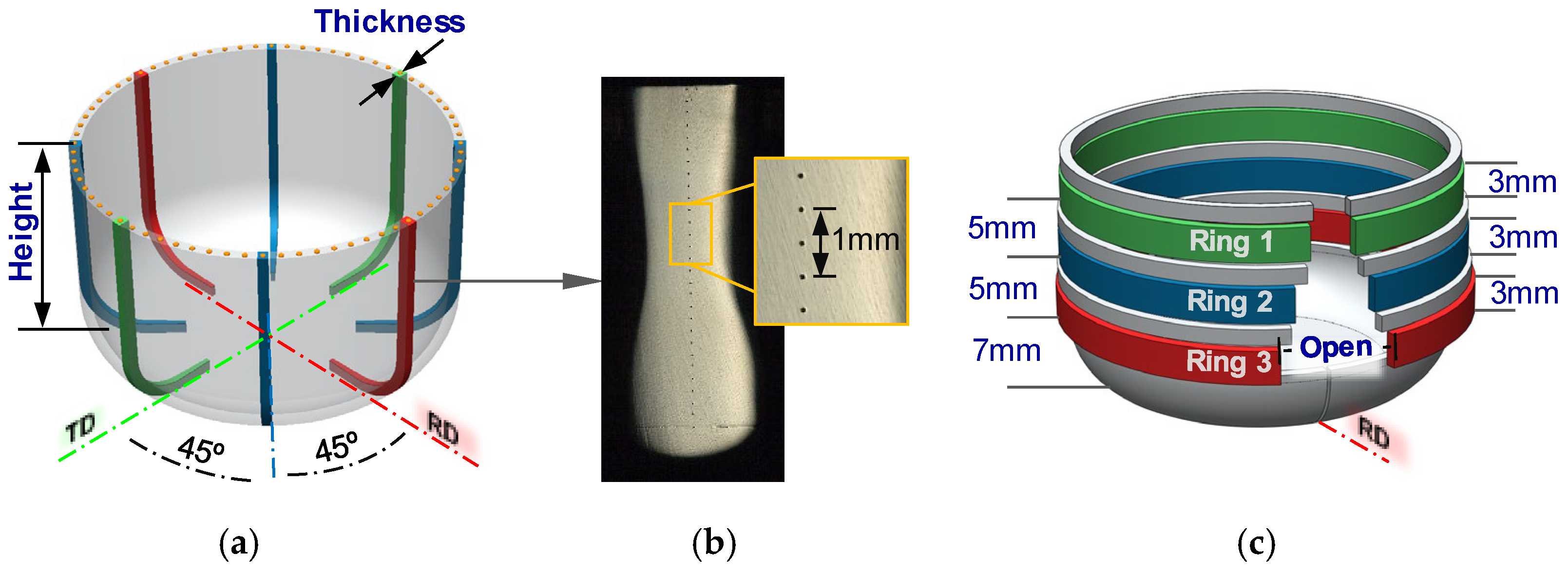
The cup thickness and height were measured, as shown in Figure 7a. Thickness was measured from the cup centre to its top in 0.50 mm steps, at every 45°, from 0° to 270°. Cup height was measured along the edge at 5° intervals, from 0° to 355°. The reported values of thickness and height are averages considering the cup’s vertical axis symmetries (i.e., the average of the 1st, 2nd, 3rd, and 4th quadrants at each 90°). Measurements were performed using a 3D coordinate measuring machine (CMM) (MicroXcel PFX-454, Brown & Sharpe Manufacturing Co., North Kingstown, RI, USA). The measurement error was approximately ±20 µm under identical test conditions.
Figure 7.
Post-forming analysis: (a) cup dimensions, (b) hardness measurement (c), springback.
The cup wall undergoes significant deformation and temperature gradients; therefore, hardness measurements along the wall provide insight into mechanical property evolution and post-forming strength. Microhardness tests were performed along the RD, vertically along the cup wall in 0.50 mm steps; see Figure 7b. Vickers microhardness measurements were carried out using a HMV-G21D microhardness tester (Shimadzu Corporation, Kyoto, Japan). The applied load was 1.961 N (HV0.2) with a dwell time of 20 s. To improve accuracy, the surface was prepared by grinding with 1000- and 2000-grit silicon carbide papers, followed by cloth polishing with 9, 6, and 3 µm diamond suspensions. The measurement error was approximately ±1 HV. Hardness measurements were repeated across different samples and positions along the cup wall to ensure consistency.
Springback was evaluated using the split-ring test, which involves three steps: (i) cutting a ring from the cup wall (trimming); (ii) splitting the ring along the RD; and (iii) measuring the ring opening. The magnitude of the ring opening provides an indirect estimate of the circumferential residual stresses in the formed cup and is used to evaluate springback. As shown in Figure 7c, three rings were cut from different vertical positions along the cup wall, since ring opening magnitude depends on position [43,44]. Rings were cut and opened using a wire-cut electrical discharge machining (EDM). Ring openings were measured with a microscope to ensure high accuracy, and the EDM cut thickness (0.3 mm) was accounted for in the measurements. The measurement error was approximately ±0.07 mm.
3. Results
3.1. Uniaxial Tensile Tests
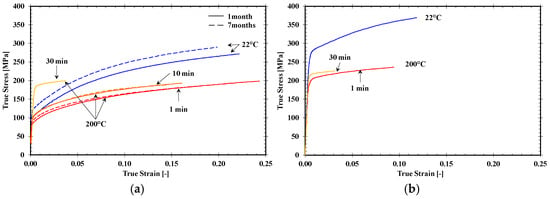
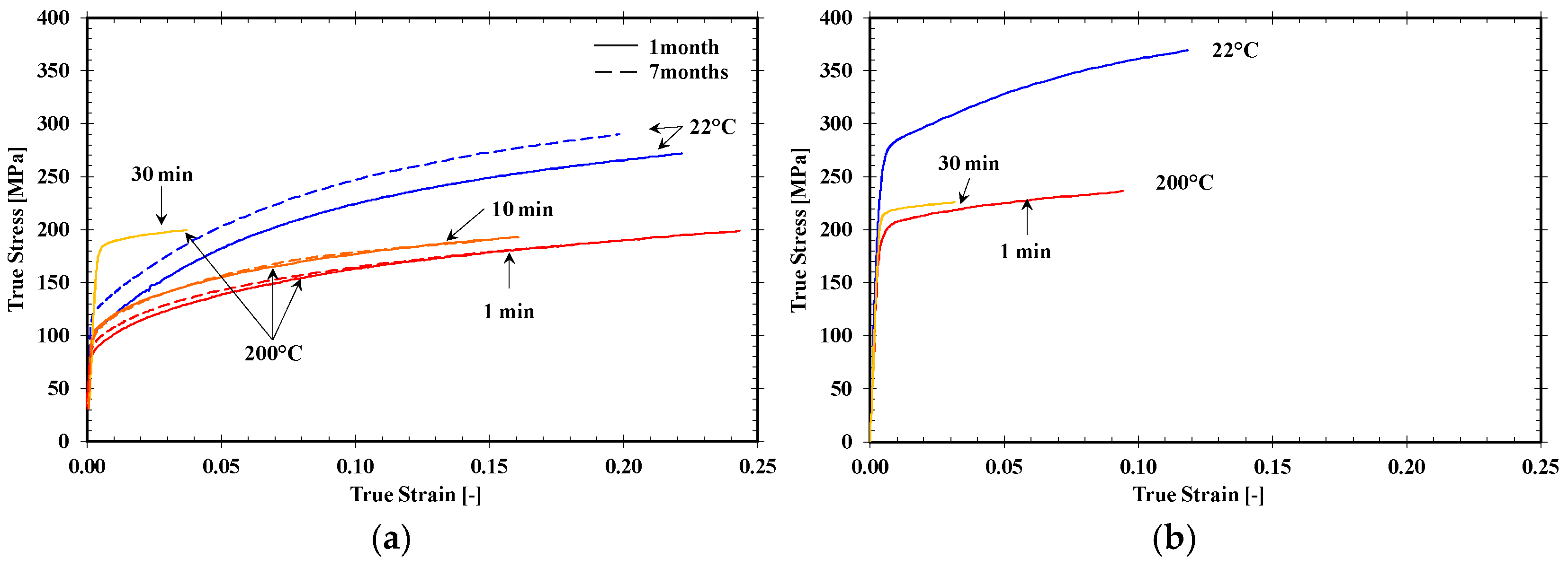
The true stress–strain curves obtained from uniaxial tensile tests are shown in Figure 8. Overall, as heat-holding time at 200 °C increases, both alloys exhibit higher strength and reduced ductility. This change in mechanical behaviour results in increased yield stress and tensile strength, while the strain-hardening rate decreases. However, the effect of heat-holding time is more pronounced for EN AW 6016-T4 than for EN AW 6061-T6. Specifically, when EN AW 6016-T4 is subjected to a heat-holding time of 30 min, its mechanical behaviour becomes similar to that of EN AW 6061-T6, i.e., typical of a T6 heat treatment. At 200 °C and 30 min, EN AW 6016-T4 shows a yield stress higher than that observed at RT. Regarding natural ageing effects on EN AW 6016-T4, for a heat-holding time of 1 min, the yield stress is higher for specimens aged 7 months; whereas for 10 min, the stress–strain curves of specimens aged 1- and 7-months overlap. For EN AW 6061-T6, heat-holding time has a limited influence on mechanical behaviour. Even after 30 min, the yield stress increases slightly but remains lower at 200 °C than at RT.
Figure 8.
Influence of heat-holding time on the stress–strain curves: (a) EN AW 6016-T4, (b) EN AW 6061-T6. The results are presented as true stress–true strain, plotted up to the maximum load.
The evolution of the stress–strain curves in Figure 8 reflects the combined effects of strain hardening and thermal exposure. For EN AW 6016-T4, the increase in yield strength and reduction in ductility with longer holding times suggest progressive artificial ageing, with the formation and growth of β″ precipitates. The decrease in strain hardening rate is consistent with the reduced capacity for dislocation storage due to precipitation. For EN AW 6061-T6, the curves show limited variation, indicating high thermal stability and minimal microstructural evolution at 200 °C. No evidence of dynamic or static recrystallization was observed under the tested conditions, likely due to the moderate strain levels and sub-critical temperatures.
3.2. Warm Forming
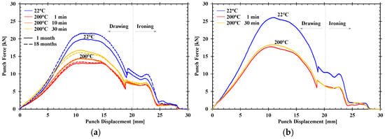
The influence of heat-holding time on the evolution of punch force with displacement is shown in Figure 9. Overall, material softening at 200 °C results in a lower punch force compared with room-temperature (RT) tests. Under warm-forming conditions, both alloys exhibit an increase in punch force with increasing heat-holding time. However, the EN AW-6016-T4 alloy shows a stronger dependence on heat-holding time.
Figure 9.
Punch force versus displacement curves during the forming of the cylindrical cups: (a) EN AW 6016-T4, (b) EN AW 6061-T6.
During the drawing phase, the punch force increases rapidly up to a displacement of approximately 11 mm, which corresponds to the displacement where the die and punch shoulder radii are fully formed in the blank. Afterward, the punch force decreases and reaches a local minimum at around 19 mm of punch displacement. This local minimum is related to the absence of a blank-holder stopper, leading the blank-holder to push the blank into the die cavity and thereby lowering the punch force required. The ironing stage begins at approximately 20 mm of punch displacement. This phase is characterized by an initial force plateau, followed by a decrease in punch force toward the end of the forming process.
3.3. Cup Profile
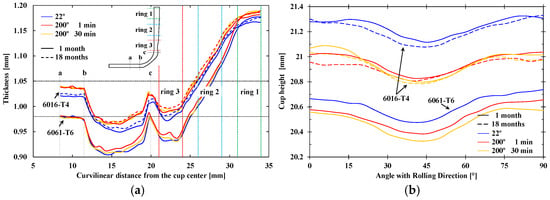
The cup thickness and height profiles are shown in Figure 10. The thickness profiles (see Figure 10a) show distinct regions, corresponding to the cup bottom, the punch radius, and the vertical wall. At the cup bottom, the thickness remains nearly constant and close to the initial sheet thickness. In the punch radius, the thickness reaches its minimum, with two critical points: the entrance to the punch radius section and the junction between the punch radius and the cup wall [45,46]. Along the vertical wall, the thickness increases progressively until it stabilizes at a constant value determined by the ironing stage. This thickness profile evolution is consistent across all tests and results directly from the cup geometry and deformation mechanics. Figure 10b shows the cup height, or ear profile. This profile results from the material’s anisotropy and exhibits a similar shape for both alloys tested. The maximum cup height occurs along the RD and at 90° to the RD, while the minimum is at 45° to the RD, which is typical for materials with Δr > 0 [47]. Due to volume conservation, a correlation exists between the average cup height and average thickness: cups with higher heights generally show slightly reduced average thickness. Overall, shapes of the cup thickness and the cup height profile remain similar among all tests conducted, regardless of heat-holding time. However, for both alloys, cups formed at 200 °C exhibit greater thickness and lower cup height compared to those formed at RT. Additionally, the threshold thickness imposed by the ironing stage is higher at 200 °C than at RT, due to thermal expansion of the tools at elevated temperature [38]. The influence of heat-holding time at 200 °C on the geometric profiles is negligible relative to the dominant effect of temperature. Finally, when comparing the two alloys, the EN AW 6061-T6 alloy exhibits lower thickness and cup height values than the EN AW 6016-T4 alloy. This difference is attributed to the lower initial sheet thickness of the EN AW 6061-T6 alloy (0.98 mm) compared to the EN AW 6016-T4 alloy (1.05 mm), as shown in Table 1.
Figure 10.
Influence of heat-holding time on the cylindrical cup profile. (a) Thickness profile along RD. (b) Cup height.
3.4. Hardness
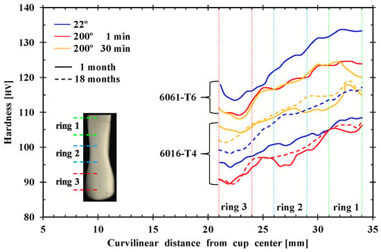
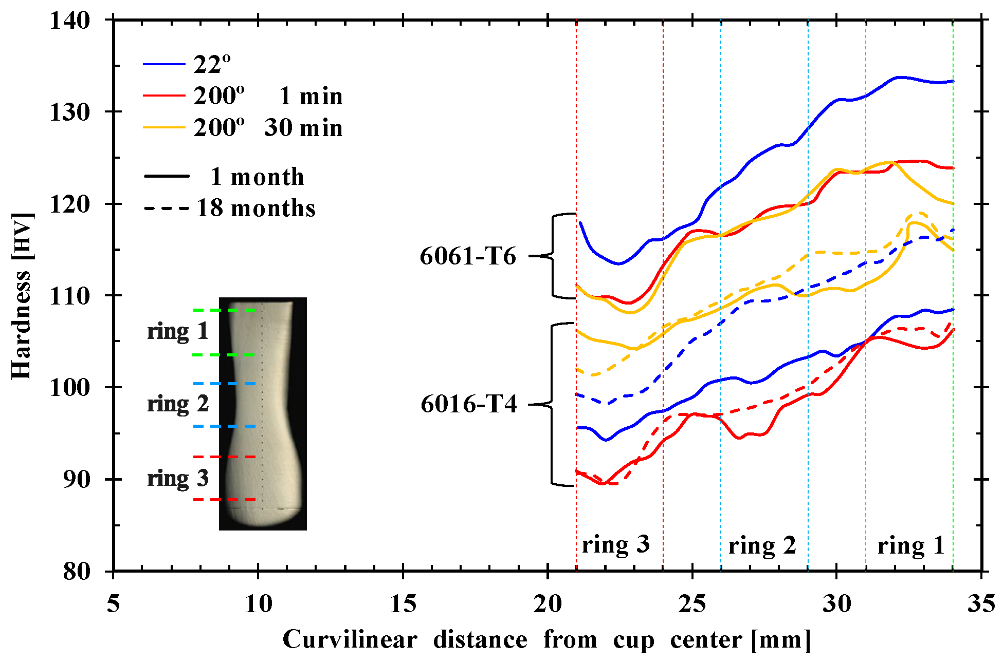
The mechanical properties after forming were evaluated by microhardness tests performed along the cup wall, as hardness correlates to some extent with material strength. The cup hardness profiles are shown in Figure 11, corresponding to measurements taken along the RD of the cup wall. Overall, hardness increases from the cup bottom to the top; that is, at Ring 3 the material is the softest, while at Ring 1 it is the hardest, which can be attributed to the work hardening gradient along the cup wall.
Figure 11.
Influence of heat-holding time on the hardness evolution along the cup profile in the RD.
For the EN AW 6016-T4 alloy, increasing the heat-holding time leads to a general increase in hardness along the cup wall. Specifically, cups formed with a heat-holding time of 30 min exhibit the highest hardness values, while those formed with a heat-holding time of 1 min show the lowest; cups formed at RT have intermediate hardness values compared to those formed at 200 °C. Regarding natural ageing of the EN AW 6016-T4 alloy, although natural ageing increases the hardness of the cup at RT, at 200 °C its effect on cup hardness is negligible.
For the EN AW 6061-T6 alloy, cups formed at RT present the highest hardness values, while at 200 °C, heat-holding time has no significant influence on hardness evolution. Finally, for both alloys, the hardness values of the formed cups are always higher than those of the as-received material (see Table 1). This indicates that increasing temperature and heat-holding time does not promote material softening or strength loss in the formed cup.
According to Asgharzadeh et al. [48], the yield stress (Rp0.2) and tensile strength (Rm) of Al–Mg–Si alloys can be correlated with hardness in MPa by the equations 1 and 2, respectively:
Rp0.2 = 2.66 × H − 13.215
Rm = 2.51 × H + 31.99
Although these equations provide a good estimate for the results reported in this work, they should be used only as an approximation, since precipitation mechanisms can alter this linear correlation [49].
3.5. Springback: The Split-Ring Test
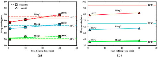
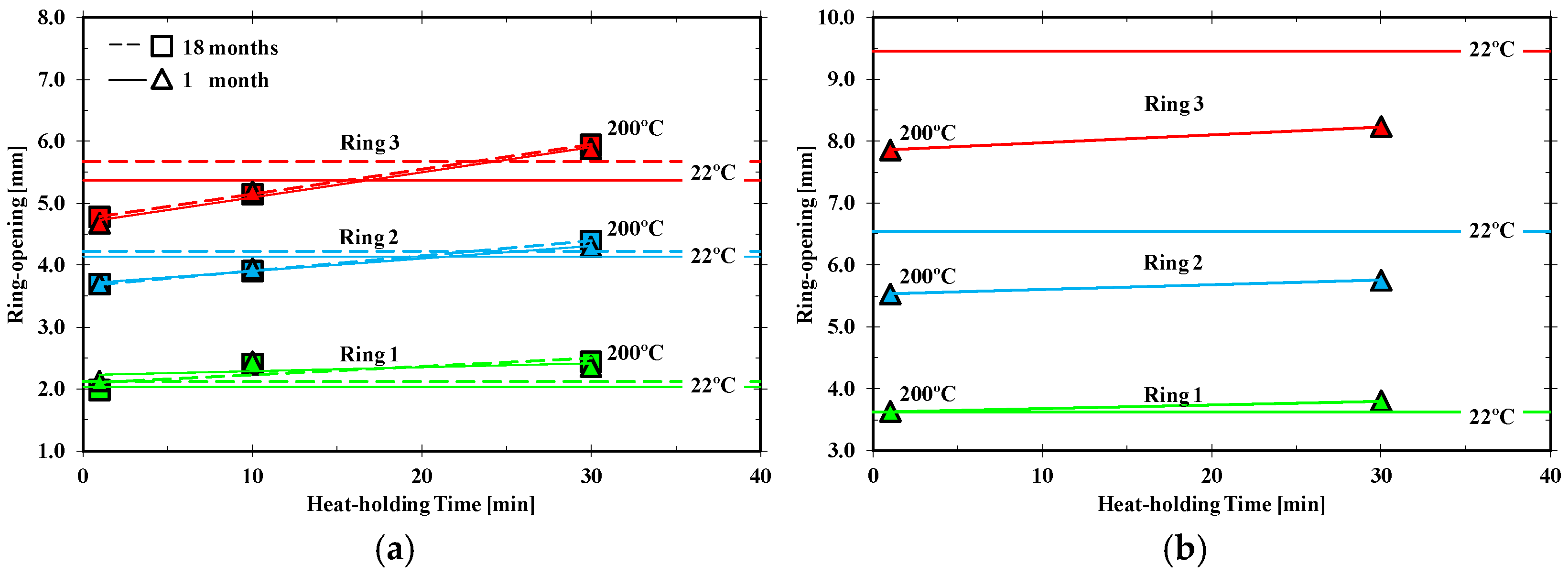
Springback was evaluated by cutting three rings from the cup wall at various heights, as previously shown in Figure 7c. Figure 12 presents the springback results for the EN AW 6016-T4 and EN AW 6061-T6 alloys, respectively. Horizontal lines indicate the springback values at RT and serve as a reference to analyse the heat-holding time influence. A clear positional trend is observed: the ring opening decreases with increasing distance from the cup bottom. Specifically, Ring 3 (closest to the bottom) consistently exhibits the largest opening, whereas Ring 1 (near the cup top) shows the smallest. This behaviour is identical for both alloys and is independent of heat-holding time and forming temperature, as will be discussed later.
Figure 12.
Ring opening as a function of heat-holding time for tests performed at RT and 200 °C: (a) EN AW 6016-T4, (b) EN AW 6061-T6. The horizontal lines (measured at RT) serve as reference values for each ring, which are always represented by colour: green (Ring 1), blue (Ring 2), and red (Ring 3).
At 200 °C, springback increases with increasing heat-holding time. For EN AW-6016-T4, this effect is pronounced: after 30 min of heat holding, the springback exceeds the values measured at room temperature (RT). However, the combined influence of natural ageing and heat holding at 200 °C is minimal, even though natural ageing noticeably increases springback at RT. In contrast, for EN AW-6061-T6, the increase in springback after 30 min of heat holding is relatively small. Under all comparable test conditions, EN AW-6061-T6 consistently exhibits higher springback than EN AW-6016-T4.
4. Discussion
Overall, warm forming with reduced heat-holding time improves formability and reduces springback, while maintaining good post-forming properties. However, the advantages of warm forming over RT forming can be compromised when high heat-holding times are used, as previously discussed for 7xxx aluminium alloys [4,27]. Increasing the heat-holding time promotes higher strength and lower ductility, with this effect being more pronounced in the naturally aged EN AW 6016-T4 alloy than in the artificially aged EN AW 6061-T6 alloy. In fact, T6-tempered alloys are thermally more stable than those in the T4 temper. The increase in strength due to longer heat-holding times results in higher cup drawing forces, higher hardness along the cup wall, and increased springback. Although ductility decreases with increased heat-holding time, this does not significantly affect the formability of the cylindrical cups, except for a greater thickness reduction observed at higher heat-holding times.
The results from tensile tests are consistent with those from the cylindrical cup tests. For the EN AW 6016-T4 alloy, increasing the heat-holding time from 1 to 30 min leads to a significant increase in tensile strength, such that the yield stress at 200 °C becomes higher than at 22 °C. In fact, a 30-min heat-holding time for the EN AW 6016-T4 alloy effectively results in a T6 heat treatment [23]. Furthermore, the punch force evolution for EN AW 6016-T4 with the longest heat-holding time closely resembles that of EN AW 6061-T6, confirming a hardening behaviour similar to T6. The EN AW 6061-T6 alloy shows only a slight increase in tensile strength and drawing force for a 30-min heat-holding time.
Post-forming strength was analysed by microhardness tests along the cup wall, which is subjected to significant deformation and temperature gradients. The hardness profiles show increasing values from the punch radius to the top of the vertical wall, i.e., hardness increases gradually with plastic deformation [50]. The shape of the hardness curve (Figure 11) is similar to that of the thickness profile along the vertical wall (Figure 10), both resulting from the cup geometry and imposed deformation. According to Fang et al. [51], the material in the cup wall experiences longitudinal elongation and uniaxial tensile stress, leading to significant increases in microhardness. Additionally, since the hardness profile is similar at RT and at an elevated temperature, the mechanical properties can be considered reliable after warm forming [52]. For both alloys, the hardness values in the cups are always higher than in the as-received material (see Table 1), indicating that increased temperature and heat-holding time do not promote material softening or strength loss in the formed cup [24]. Notably, after 30 min of heat-holding, the EN AW 6016-T4 alloy achieves cup wall hardness values higher than those of a T6 heat treatment (105 HV, see [53]).
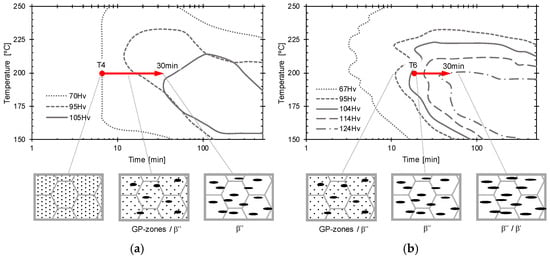
The schematic diagrams in Figure 13 analyse the expected hardness evolution for heat-holding times between 1 and 30 min at 200 °C for both alloys based on the conceptual framework and trends reported in the literature, namely in the works of Schiffmann et al. [53] and Pogatscher et al. [36].
Figure 13.
Time–temperature–hardness diagrams: (a) EN AW 6016-T4, (b) EN AW 6061-T6, illustrating the influence of heat-holding time on hardness and microstructural evolution.
The hardness values obtained are equivalent to or higher than those reported in the literature, confirming that heat-holding times up to 30 min do not promote material softening. Zandbergen et al. [54] studied the correlation between hardness and precipitation in Al–Mg–Si alloys using atom probe tomography and hardness measurements. According to their study, 10 min of artificial ageing mainly produces short, elongated precipitates (6–10 nm) with high Mg-Si cluster density and hardness around 80 HV, while 30 min of artificial ageing leads to some precipitates growing to 10–30 nm and hardness values of 109 HV. Further artificial ageing up to 4 h does not significantly increase precipitate size or hardness.
Comparing Figure 13 with Figure 11 shows that, in the region corresponding to the cup bottom (Ring 3), the material has hardness values similar to the as-received state (see Table 1), while at the cup top (Ring 1), the hardness is higher than both the as-received material and the values predicted by the TTH diagrams. Residual dislocations induced by plastic deformation at a high temperature alter the precipitation mechanisms in 6xxx series aluminium alloys [55]. These dislocations strengthen the material and act as nucleation sites for pre-β’’ phase precipitates, accelerating precipitation. However, the precipitates tend to accumulate around dislocations during subsequent artificial ageing, leading to a coarser distribution and loss of peak strength (see Figure 13 for details). Therefore, predicting post-forming strength is complex due to the interplay of thermal softening, plastic deformation (dislocation strengthening), and precipitation strengthening [24].
Although this study does not include direct microstructural observations via TEM, the measured hardness results were compared with data from the literature that quantify precipitate evolution in Al–Mg–Si alloys under artificial ageing. For instance, Zandbergen et al. [54] demonstrated, using TEM and atom probe tomography (APT), that β″ precipitates with sizes between 4 and 10 nm form after 10 min at 200 °C, while 30-min exposures promote growth in size, with corresponding significant increases in hardness. These values are consistent with the hardness profiles measured along the cup wall in this study, particularly for the EN AW 6016-T4 alloy after 30 min of holding time. Therefore, the correlation between holding time, precipitation hardening, and mechanical properties is supported by indirect evidence in this work and by quantitative data from the literature. This reinforces the validity of the conclusions, even in the absence of direct microstructural characterization.
Springback analysis provides insight into the influence of temperature and heat-holding time on residual stresses in the formed cups. The split-ring test evaluates the magnitude of circumferential stresses in the cylindrical cup. The profiles of axial and circumferential residual stresses in cylindrical cups were described by Simões et al. [44], highlighting their strong dependence on axial position. It was observed that the ring opening decreases with increasing distance from the cup bottom, as the ironing stage reduces the through-thickness gradient of circumferential stress. These findings are consistent with those in Figure 12, where the relatively constant springback values for Ring 1 should be noted. In fact, springback decreases as the distance from the cup bottom increases, while hardness increases as the distance from the cup bottom decreases; this is because springback is governed by the equilibrium of internal stresses, whereas hardness reflects material strength and microstructure.
Regarding the effect of temperature on springback, the literature shows that warm forming is highly effective in reducing springback [56,57]. For a given Young’s modulus, springback increases with increasing yield stress [57]. Thus, the higher springback values observed in Figure 12 are linked to the higher yield stress values from tensile tests at RT or with longer heat-holding times (see Figure 8). Conversely, reducing yield stress by increasing forming temperature and using shorter heat-holding times leads to reduced springback, as shown in Figure 12. Similarly, for the EN AW 6016-T4 alloy at 200 °C, springback is higher for 30 min than for 1 min of heat-holding time. Under the same test conditions, the EN AW 6061-T6 alloy always exhibits higher springback values than the EN AW 6016-T4 alloy.
Regarding natural ageing in the EN AW 6016-T4 alloy, at RT, the material aged for 7 months shows higher strength than that aged for 1 month (Figure 8), resulting in higher punch force, hardness, and springback. At 200 °C, the difference between the 18-month and 1-month aged materials is almost negligible [38]. However, for a heat-holding time of 1 min, the 18-month aged material shows slightly higher strength, while for 30 min, it shows lower strength than the 1-month aged material, resulting in lower punch force, hardness, and springback. This behaviour is related to the negative effect of natural ageing on artificial ageing [36,58]: natural ageing precipitates formed at RT must dissolve at elevated temperatures to form new artificial ageing precipitates, reducing precipitation kinetics.
5. Conclusions
The present study investigated the thermo-mechanical behaviour of Al–Mg–Si alloys at RT and 200 °C, focusing on ductility, springback, and post-forming strength. The main objective was to understand the influence of heat-holding time during the warm forming of heat-treatable aluminium alloys.
Warm forming with reduced heat-holding time improves formability and reduces springback while maintaining good post-forming strength. However, prolonged heating and holding times can induce microstructural changes due to static precipitation, leading to reduced ductility and increased springback, even though post-forming strength remains high. Therefore, heat-holding time is a crucial parameter for the thermo-mechanical response of heat-treatable aluminium alloys.
A comparison between tests at RT and those performed under warm forming conditions shows the following:
- Regardless of the heat-holding time selected, warm forming improves formability while maintaining good post-forming strength.
- Increasing the heat-holding time up to 30 min leads to higher yield stress and tensile strength, but reduces total elongation. Consequently, warm forming with longer heat-holding times results in increased springback and hardness. This effect is significant for the EN AW 6016-T4 alloy but negligible for the EN AW 6061-T6 alloy. It is also noteworthy that the cups do not exhibit significant differences in thickness profiles, indicating no remarkable differences in formability.
- Extending the heat-holding time up to 30 min has a negligible impact on the warm forming of the EN AW 6061-T6 alloy, indicating that over-ageing does not occur. For the EN AW 6016-T4 alloy, the reduction in ductility and increase in strength are associated with a transition from natural to artificial ageing. Therefore, for the EN AW 6016-T4 alloy, a heat-holding time of less than 10 min during warm forming is recommended.
In conclusion, the main negative effect of increasing heat-holding time during warm forming is the rise in springback, as longer heat-holding times can lead to springback values that even exceed those observed at RT.
Supplementary Materials
The following supporting information can be downloaded at: https://www.mdpi.com/article/10.3390/jmmp10030094/s1. Video S1 is cited in Figure 5 caption.
Author Contributions
V.S.: Investigation, Experiments, Data curation, Conceptualization, Writing—original draft. M.O.: Investigation, Formal analysis, Writing—review & editing. H.L.: Investigation, Methodology, Writing—review & editing. L.M.: Investigation, Supervision, review & editing. All authors have read and agreed to the published version of the manuscript.
Funding
This research was sponsored by national funds from the French Ministry of Higher Education and from the Portuguese Foundation for Science and Technology (FCT) under projects UID/00285/2025, LA/P/0112/2020, LSD-TRIP (2023.16367.ICDT) and REACH (15577: COMPETE2030-FEDER-00663900). The first author Vasco Simões is also grateful to the FCT for the PhD grant SFRH/BD/90669/2012.
Data Availability Statement
The original contributions presented in this study are included in the article/Supplementary Material. Further inquiries can be directed to the corresponding author.
Acknowledgments
The authors are grateful to Constellium for supplying the material. Moreover, the authors acknowledge the technical staff of IRDL for their help in some of the experimental procedures (Anthony Jégat and Hervé Bellegou).
Conflicts of Interest
The authors declare no conflicts of interest.
References
- Neugebauer, R.; Altan, T.; Geiger, M.; Kleiner, M.; Sterzing, A. Sheet Metal Forming at Elevated Temperatures. CIRP Ann.—Manuf. Technol. 2006, 55, 793–816. [Google Scholar] [CrossRef] [Scilit]
- Shojaei, K.; Sajadifar, S.V.; Yapici, G.G. On the Mechanical Behavior of Cold Deformed Aluminum 7075 Alloy at Elevated Temperatures. Mater. Sci. Eng. A 2016, 670, 81–89. [Google Scholar] [CrossRef] [Scilit]
- Kumar, M.; Sotirov, N.; Chimani, C.M. Investigations on Warm Forming of AW-7020-T6 Alloy Sheet. J. Mater. Process. Technol. 2014, 214, 1769–1776. [Google Scholar] [CrossRef] [Scilit]
- Feng, Z.; Liu, C.; Ma, P.; Yang, J.; Chen, K.; Li, G.; Chen, L.; Huang, Z. Initial Holding Time Dependent Warm Deformation and Post-Ageing Precipitation in an AA7075-T4 Aluminum Alloy. J. Mater. Process. Technol. 2021, 294, 117111. [Google Scholar] [CrossRef] [Scilit]
- Mori, K.; Bariani, P.F.; Behrens, B.-A.; Brosius, A.; Bruschi, S.; Maeno, T.; Merklein, M.; Yanagimoto, J. Hot Stamping of Ultra-High Strength Steel Parts. CIRP Ann. 2017, 66, 755–777. [Google Scholar] [CrossRef] [Scilit]
- Lee, E.-H.; Hwang, J.-S.; Lee, C.-W.; Yang, D.-Y.; Yang, W.-H. A Local Heating Method by Near-Infrared Rays for Forming of Non-Quenchable Advanced High-Strength Steels. J. Mater. Process. Technol. 2014, 214, 784–793. [Google Scholar] [CrossRef] [Scilit]
- Kolleck, R.; Veit, R.; Merklein, M.; Lechler, J.; Geiger, M. Investigation on Induction Heating for Hot Stamping of Boron Alloyed Steels. CIRP Ann. 2009, 58, 275–278. [Google Scholar] [CrossRef] [Scilit]
- Boyer, A.; Germain, L.; Laurent, H.; Neto, D.M.; Oliveira, M.C. Numerical Analysis of the Bulge Test in Temperature for the EN AW 6061-T6 Sheet. In IOP Conference Series: Materials Science and Engineering; IOP Publishing: Bristol, UK, 2020; Volume 967, p. 012024. [Google Scholar] [CrossRef] [Scilit]
- Harrison, N.R.; Friedman, P.A.; Pan, J. Warm Forming Die Design, Part III: Design and Validation of a Warm Forming Die. J. Manuf. Process. 2015, 20, 356–366. [Google Scholar] [CrossRef] [Scilit]
- Liu, X.; Ji, K.; Fakir, O.E.; Fang, H.; Gharbi, M.M.; Wang, L. Determination of the Interfacial Heat Transfer Coefficient for a Hot Aluminium Stamping Process. J. Mater. Process. Technol. 2017, 247, 158–170. [Google Scholar] [CrossRef] [Scilit]
- Billur, E.; Altan, T. Warm Forming of Alloys in the Auto Industry: An Alternative to Struggling with Straight Stamping of Aluminum Alloys Has Emerged; R&D Update; The Fabricator: Elgin, IL, USA, 2013. [Google Scholar]
- Morris, L.R.; George, R.A. Warm Forming High-Strength Aluminum Automotive Parts; SAE International: Warrendale, PA, USA, 1977. [Google Scholar]
- Long, R.S.; Boettcher, E.; Crawford, D. Current and Future Uses of Aluminum in the Automotive Industry. JOM 2017, 69, 2635–2639. [Google Scholar] [CrossRef] [Scilit]
- Long, R.; Newman, J.; James, W. Development of Low Cost High Strength Automotive Aluminum Sheet (Arconic); Vehicle Technologies Office—U.S. Office of Energy Efficiency & Renewable Energy: Washington, DC, USA, 2018; pp. 136–142.
- Kim, H. Warm Forming of High-Strength Aluminum Automotive Structural Parts: A Success Story; EWI: Columbus, OH, USA, 2018. [Google Scholar]
- Grohmann, T. Forming of AMAG 7xxx Series Aluminium Sheet Alloys. In Proceedings of the New Developments in Sheet Metal Forming and New Developments in Hydroforming; University of Stuttgart: Stuttgart, Germany, 2016. [Google Scholar]
- Polak, S.; Kaczyński, P.; Gronostajski, Z.; Jaskiewicz, K.; Krawczyk, J.; Skwarski, M.; Zwierzchowski, M.; Chorzępa, W. Warm Forming of 7075 Aluminum Alloys. Procedia Eng. 2017, 207, 2399–2404. [Google Scholar] [CrossRef] [Scilit]
- Gronostajski, Z.; Polak, S.; Jaśkiewicz, K.; Kaczyńskia, P.; Skwarski, M.; Krawczyk, J.; Chorzępa, W.; Śliz, K.; Uzar, S. Properties of B-Pillar Made of Aluminium 7075 in Warm Forming Process. Procedia Manuf. 2019, 27, 98–103. [Google Scholar] [CrossRef] [Scilit]
- Palumbo, G.; Piccininni, A.; Guglielmi, P.; Spina, R.; Tricarico, L.; Sorgente, D.; Russello, G.; Vitrano, A.; Franco, A.L. Warm Forming of an AA5754 Component for Railway Vehicle Applications. Procedia Eng. 2017, 183, 351–356. [Google Scholar] [CrossRef] [Scilit]
- Grèze, R.; Manach, P.Y.; Laurent, H.; Thuillier, S.; Menezes, L.F. Influence of the Temperature on Residual Stresses and Springback Effect in an Aluminium Alloy. Int. J. Mech. Sci. 2010, 52, 1094–1100. [Google Scholar] [CrossRef] [Scilit]
- Panicker, S.S.; Prasad, K.S.; Basak, S.; Panda, S.K. Constitutive Behavior and Deep Drawability of Three Aluminum Alloys Under Different Temperatures and Deformation Speeds. J. Mater. Eng Perform. 2017, 26, 3954–3969. [Google Scholar] [CrossRef] [Scilit]
- Palumbo, G.; Piccininni, A.; Guglielmi, P.; Di Michele, G. Warm HydroForming of the Heat Treatable Aluminium Alloy AC170PX. J. Manuf. Process. 2015, 20, 24–32. [Google Scholar] [CrossRef] [Scilit]
- Ghosh, M.; Miroux, A.; Werkhoven, R.J.; Bolt, P.J.; Kestens, L.A.I. Warm Deep-Drawing and Post Drawing Analysis of Two Al–Mg–Si Alloys. J. Mater. Process. Technol. 2014, 214, 756–766. [Google Scholar] [CrossRef] [Scilit]
- Fan, X.; He, Z.; Zhou, W.; Yuan, S. Formability and Strengthening Mechanism of Solution Treated Al–Mg–Si Alloy Sheet under Hot Stamping Conditions. J. Mater. Process. Technol. 2016, 228, 179–185. [Google Scholar] [CrossRef] [Scilit]
- Kumar, M.; Ross, N.G. Influence of Temper on the Performance of a High-Strength Al–Zn–Mg Alloy Sheet in the Warm Forming Processing Chain. J. Mater. Process. Technol. 2016, 231, 189–198. [Google Scholar] [CrossRef] [Scilit]
- Bariani, P.F.; Bruschi, S.; Ghiotti, A.; Michieletto, F. Hot Stamping of AA5083 Aluminium Alloy Sheets. CIRP Ann. 2013, 62, 251–254. [Google Scholar] [CrossRef] [Scilit]
- Royne, S.; Laurent, H.; Maillard, A. Optimum Heating Time for Warm Forming of AA7075 Aluminum Alloy in T6 Condition. Int. J. Adv. Manuf. Technol. 2024, 133, 6005–6021. [Google Scholar] [CrossRef] [Scilit]
- Deschamps, A.; Livet, F.; Bréchet, Y. Influence of Predeformation on Ageing in an Al–Zn–Mg Alloy—I. Microstructure Evolution and Mechanical Properties. Acta Mater. 1998, 47, 281–292. [Google Scholar] [CrossRef] [Scilit]
- Clouet, E.; Nastar, M.; Sigli, C. Nucleation of Al3Zr and Al3Sc in Aluminum Alloys: From Kinetic Monte Carlo Simulations to Classical Theory. Phys. Rev. B 2004, 69, 064109. [Google Scholar] [CrossRef] [Scilit]
- Marioara, C.D.; Andersen, S.J.; Zandbergen, H.W.; Holmestad, R. The Influence of Alloy Composition on Precipitates of the Al–Mg–Si System. Met. Mater. Trans. A 2005, 36, 691–702. [Google Scholar] [CrossRef] [Scilit]
- Myhr, O.; Grong, Ø.; Andersen, S.J. Modelling of the Age Hardening Behaviour of Al–Mg–Si Alloys. Acta Mater. 2001, 49, 65–75. [Google Scholar] [CrossRef] [Scilit]
- Hou, X.; Qi, P.; Li, B.; Wen, S.; Wei, W.; Qi, Y.; Yin, J.; Nie, Z. Precipitation Behavior and Mechanical Properties of Al–1.0Mg–0.6Si–Cu (Wt.%) Alloy Controlled by Cu Content. Appl. Phys. A 2023, 129, 281. [Google Scholar] [CrossRef] [Scilit]
- Rao, Y.; Li, A.; Zuo, T.; Wang, L.; Hu, Y.; Lu, B. Influence of Different Rolling Processes on the Microstructures and Mechanical Properties of 6016 Aluminum Alloy. Appl. Phys. A 2023, 129, 690. [Google Scholar] [CrossRef] [Scilit]
- ISO 6892-1; Metallic Materials—Tensile Testing—Part 1: Method of Test at Room Temperature. International Organization for Standardization: Geneva, Switzerland, 2009; p. 65.
- Buha, J.; Lumley, R.N.; Crosky, A.G.; Hono, K. Secondary Precipitation in an Al–Mg–Si–Cu Alloy. Acta Mater. 2007, 55, 3015–3024. [Google Scholar] [CrossRef] [Scilit]
- Pogatscher, S.; Antrekowitsch, H.; Leitner, H.; Ebner, T.; Uggowitzer, P.J. Mechanisms Controlling the Artificial Aging of Al–Mg–Si Alloys. Acta Mater. 2011, 59, 3352–3363. [Google Scholar] [CrossRef] [Scilit]
- Wang, H.; Luo, Y.; Friedman, P.; Chen, M.; Gao, L. Warm Forming Behavior of High Strength Aluminum Alloy AA7075. Trans. Nonferrous Met. Soc. China 2012, 1, 1–7. [Google Scholar] [CrossRef] [Scilit]
- Simões, V.M.; Laurent, H.; Oliveira, M.C.; Menezes, L.F. The Influence of Warm Forming in Natural Aging and Springback of Al–Mg–Si Alloys. Int. J. Mater. Form. 2019, 12, 57–68. [Google Scholar] [CrossRef] [Scilit]
- ISO 6892-2; Metallic Materials—Tensile Testing—Part 2: Method of Test at Elevated Temperature. International Organization for Standardization: Geneva, Switzerland, 2011; p. 20.
- ISO 11531; Metallic Materials—Earing Test—Sheet and Strip. International Organization for Standardization: Geneva, Switzerland, 1994; p. 4.
- Palumbo, G.; Tricarico, L. Numerical and Experimental Investigations on the Warm Deep Drawing Process of Circular Aluminum Alloy Specimens. J. Mater. Process. Technol. 2007, 184, 115–123. [Google Scholar] [CrossRef] [Scilit]
- Chang, Y.; Tang, X.; Zhao, K.; Hu, P.; Wu, Y. Investigation of the Factors Influencing the Interfacial Heat Transfer Coefficient in Hot Stamping. J. Mater. Process. Technol. 2016, 228, 25–33. [Google Scholar] [CrossRef] [Scilit]
- Gnaeupel-Herold, T.; Foecke, T.; Prask, H.J.; Fields, R.J. An Investigation of Springback Stresses in AISI-1010 Deep Drawn Cups. Mater. Sci. Eng. A 2005, 399, 26–32. [Google Scholar] [CrossRef] [Scilit]
- Simões, V.M.; Oliveira, M.C.; Neto, D.M.; Cunha, P.M.; Laurent, H.; Alves, J.L.; Menezes, L.F. Numerical Study of Springback Using the Split-Ring Test: Influence of the Clearance between the Die and the Punch. Int. J. Mater. Form. 2018, 11, 325–337. [Google Scholar] [CrossRef] [Scilit]
- Colgan, M.; Monaghan, J. Deep Drawing Process: Analysis and Experiment. J. Mater. Process. Technol. 2003, 132, 35–41. [Google Scholar] [CrossRef] [Scilit]
- Moshksar, M.M.; Zamanian, A. Optimization of the Tool Geometry in the Deep Drawing of Aluminium. J. Mater. Process. Technol. 1997, 72, 363–370. [Google Scholar] [CrossRef] [Scilit]
- Hu, P.; Liu, Y.Q.; Wang, J.C. Numerical Study of the Flange Earring of Deep-Drawing Sheets with Stronger Anisotropy. Int. J. Mech. Sci. 2001, 43, 279–296. [Google Scholar] [CrossRef] [Scilit]
- Asgharzadeh, A.; Nazari Tiji, S.A.; Esmaeilpour, R.; Park, T.; Pourboghrat, F. Determination of Hardness-Strength and -Flow Behavior Relationships in Bulged Aluminum Alloys and Verification by FE Analysis on Rockwell Hardness Test. Int. J. Adv. Manuf. Technol. 2020, 106, 315–331. [Google Scholar] [CrossRef] [Scilit]
- Ozturk, F.; Sisman, A.; Toros, S.; Kilic, S.; Picu, R.C. Influence of Aging Treatment on Mechanical Properties of 6061 Aluminum Alloy. Mater. Des. 2010, 31, 972–975. [Google Scholar] [CrossRef] [Scilit]
- Fan, X.; He, Z.; Lin, P.; Yuan, S. Microstructure, Texture and Hardness of Al–Cu–Li Alloy Sheet during Hot Gas Forming with Integrated Heat Treatment. Mater. Des. 2016, 94, 449–456. [Google Scholar] [CrossRef] [Scilit]
- Fang, J.; Mo, J.; Li, J. Microstructure Difference of 5052 Aluminum Alloys under Conventional Drawing and Electromagnetic Pulse Assisted Incremental Drawing. Mater. Charact. 2017, 129, 88–97. [Google Scholar] [CrossRef] [Scilit]
- Lang, L.; Liu, B.; Li, T.; Zhao, X.; Zeng, Y. Experimental Investigation on Hydromechanical Deep Drawing of Aluminum Alloy with Heated Media. Steel Res. Int. 2012, 83, 230–237. [Google Scholar] [CrossRef] [Scilit]
- Schiffmann, R.; Haug, J.; Banhart, J. Evolution of Precipitates during Age-Hardening of AW 6016 Alloy. In Proceedings of the Materials Forum; Trans Tech Publications Ltd.: Baech, Switzerland, 2004; Volume 28, pp. 604–609. [Google Scholar]
- Zandbergen, M.W.; Xu, Q.; Cerezo, A.; Smith, G.D.W. Study of Precipitation in Al–Mg–Si Alloys by Atom Probe Tomography I. Microstructural Changes as a Function of Ageing Temperature. Acta Mater. 2015, 101, 136–148. [Google Scholar] [CrossRef] [Scilit]
- Zhang, Q.; Luan, X.; Dhawan, S.; Politis, D.J.; Du, Q.; Fu, M.W.; Wang, K.; Gharbi, M.M.; Wang, L. Development of the Post-Form Strength Prediction Model for a High-Strength 6xxx Aluminium Alloy with Pre-Existing Precipitates and Residual Dislocations. Int. J. Plast. 2019, 119, 230–248. [Google Scholar] [CrossRef] [Scilit]
- Laurent, H.; Coër, J.; Manach, P.Y.; Oliveira, M.C.; Menezes, L.F. Experimental and Numerical Studies on the Warm Deep Drawing of an Al–Mg Alloy. Int. J. Mech. Sci. 2015, 93, 59–72. [Google Scholar] [CrossRef] [Scilit]
- Moon, Y.H.; Kang, S.S.; Cho, J.R.; Kim, T.G. Effect of Tool Temperature on the Reduction of the Springback of Aluminum Sheets. J. Mater. Process. Technol. 2003, 132, 365–368. [Google Scholar] [CrossRef] [Scilit]
- Werinos, M.; Antrekowitsch, H.; Ebner, T.; Prillhofer, R.; Curtin, W.A.; Uggowitzer, P.J.; Pogatscher, S. Design Strategy for Controlled Natural Aging in Al–Mg–Si Alloys. Acta Mater. 2016, 118, 296–305. [Google Scholar] [CrossRef] [Scilit]

Disclaimer/Publisher’s Note: The statements, opinions and data contained in all publications are solely those of the individual author(s) and contributor(s) and not of MDPI and/or the editor(s). MDPI and/or the editor(s) disclaim responsibility for any injury to people or property resulting from any ideas, methods, instructions or products referred to in the content. |
© 2026 by the authors. Licensee MDPI, Basel, Switzerland. This article is an open access article distributed under the terms and conditions of the Creative Commons Attribution (CC BY) license.