


Abstract
The applicability of two different joining processes for producing lap joints from high-strength steel sheets is investigated, reflecting their increasing use in advanced lightweight structures with demanding performance requirements. The work is primarily focused on the joining-by-forming process known as double-flush riveting, evaluated in two variants: one utilizing forged holes and the other employing machined holes. The performance of these two variants is compared with conventional fusion-based resistance spot welding using lap joints fabricated from 2 mm high-strength low-alloy S500MC steel sheets under varying geometric and process conditions, with support from finite element modelling. Results indicate that both double-flush riveting variants produce similar joint cross-sectional geometries, but the machined hole variant simplifies sheet preparation and eliminates the need for a progressive tooling system. Tensile lap-shear and peel test results reveal that double-flush riveted joints with forged holes exhibit superior strength, attributed to strain hardening in the forged regions. Furthermore, for nuggets and rivets of equivalent size, both double-flush riveting variants surpass resistance spot welding in terms of the mechanical strength of the final joints. These results suggest that double-flush riveting represents a promising alternative for assembling high-strength steel sheets in lightweight structural applications.
1. Introduction
Over the past two decades, advancements in high-strength steel sheet production have been driven by the need to enhance mechanical strength while reducing sheet thickness. This trend is especially significant in the automotive industry, where manufacturers seek to produce lighter vehicles without sacrificing crashworthiness or safety [1]. Additionally, these developments contribute to improved fuel efficiency, which in turn reduces carbon emissions and the associated environmental impacts [2].
However, high-strength steel sheets must undergo significant geometric transformations to produce the various car body components in which they are employed, including pillars, bumper beams, side panels, sills, floors, and more [3]. Therefore, despite their high strength, these alloys must also meet strict formability requirements, as sheet metal forming processes are predominantly employed in their production [4]. Ensuring adequate formability enables automakers to maximize the shaping capability of the material while avoiding common sheet metal forming defects such as necking, fracture, or wrinkling [5]. Ultimately, this enhances design flexibility and advances efforts to reduce vehicle weight to improve performance and fuel efficiency.
High-strength steels encompass several key categories for modern automotive applications. Traditional high-strength low-alloy steels (HSLA) are widely used due to their balance of strength, ductility, and cost. Advanced High-Strength Steels (AHSSs), which include dual-phase, complex-phase, martensitic, and twinning-induced plasticity grades, offer enhanced energy absorption and facilitate vehicle weight reduction [6]. Press-hardened steels (PHSs) attain superior strength through hot-stamping processes. Within the HSLA category, the S-MC series consists of modern thermomechanical rolled, micro alloyed steels that provide high yield strength and excellent cold-formability. These aspects make S-MC grades particularly suitable for applications requiring both structural performance and manufacturability, such as lighter and more sustainable vehicle designs [7].
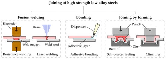
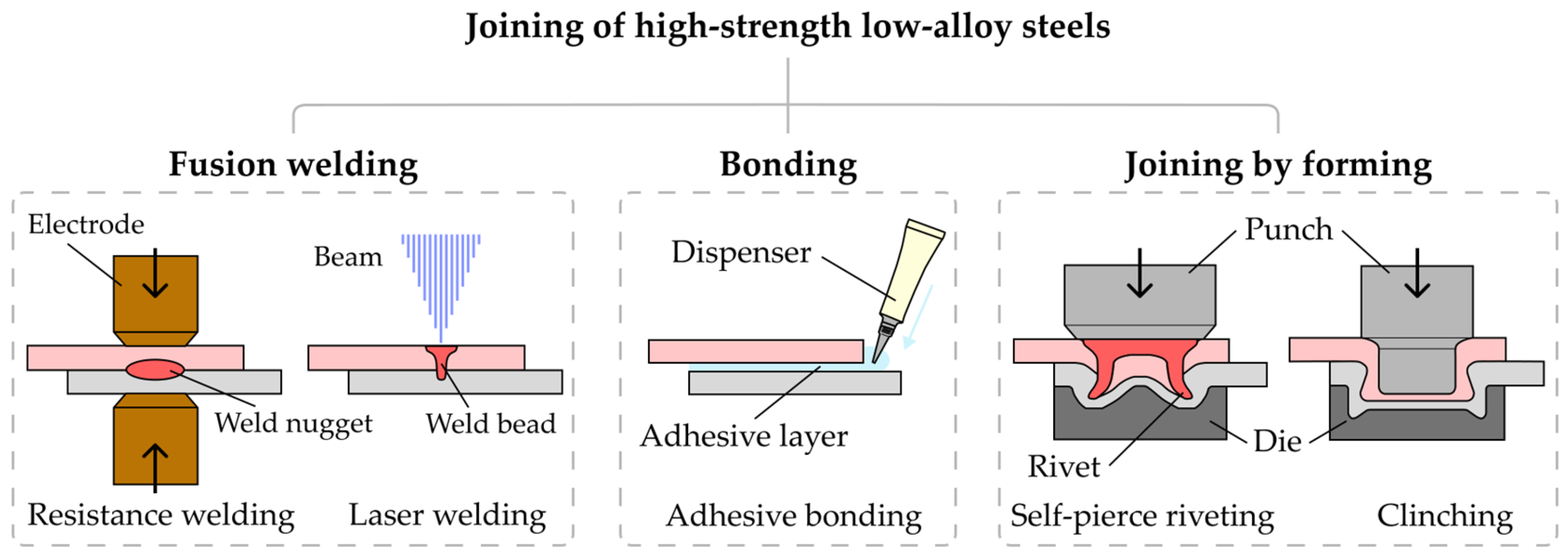
The assembly of HSLA steel components in the automotive industry demands a high degree of joinability, as reliable joining is essential for constructing complex structures Figure 1. Joinability refers to the ability of materials to be joined under specified manufacturing conditions while preserving both macrostructural and microstructural characteristics of the components prior to joining [8]. In conventional applications, fusion welding processes are the primary approaches for producing reliable joints, typically utilizing one of three thermal heat sources: electrical resistance, laser beam, or electric arc.
Figure 1.
Schematic representation of conventional joining processes and categories for producing lap joints of high-strength low-alloy steels.
Electric arc welding processes, such as gas metal arc welding and gas tungsten arc welding, and resistance spot welding remain the most used approaches, mainly because they are compatible with automated production lines equipped with robotic systems. However, recent advancements in laser technologies have made laser welding a viable alternative, particularly for edge configurations where minimizing thermal distortion is essential [9]. Nevertheless, the applicability window of fusion welding processes for HSLA steels is relatively narrow, as the microstructural transformations occurring in the heat-affected zone (HAZ) may induce brittle cracking or, conversely, critical softening, both of which may compromise the mechanical performance of the final components [10]. Stringent calibration and control of welding parameters are necessary, and this is further complicated by the inherent variability of stock materials supplied to industry.
Although bonding of HSLA steels is less commonly employed than fusion welding, it has attracted interest as an alternative because it avoids material degradation caused by heat input [11]. Nevertheless, bonding is constrained by lower productivity due to the significant energy and time required for curing structural adhesives, as well as by reduced performance, especially under corrosive conditions [12].
Joining by forming has become an attractive solution for assembling high-strength steels, such as HSLA grades, as it avoids the thermal effects associated with welding and the productivity limitations of bonding. These processes fabricate joints through controlled plastic deformation [13], resulting in robust mechanical interlocks obtained under the high productivity of conventional metal forming processes [14]. Consequently, their use has increased largely in recent years, especially within the automotive sector [15].
Recent advancements in joining by forming have primarily focused on clinching, self-pierce riveting, and hemming, which are processes applicable to HSLA sheets that facilitate the production of hybrid structures composed of dissimilar materials [16]. While these processes address several fundamental limitations of fusion welding and bonding, they also present specific challenges. In fact, all the previous joining by forming processes restrict sheet positioning and create protrusions on one or both sheet surfaces that reduce their suitability for assemblies requiring tight tolerances or minimal available space [17].
For these reasons, the authors proposed a new double-flush riveting process [18] that uses a punching-and-forming sequence to create countersunk holes, which are subsequently filled with forged rivet material. This work showed that it was indeed possible to produce countersunk holes directly during the punching stage, resulting in joints with satisfactory performance. However, the mechanical interlock was limited by the punch–die clearance, because it allows increasing the inclination angle of the conical region (i.e., greater interlock), but overly large values hinder the required countersunk hole geometry.
Given the above, the process was further developed into a new variant referred to as advanced double-flush riveting [19]. This approach incorporates a more comprehensive forging sequence to improve the geometry of countersunk holes, enabling higher inclination angles and greater geometric precision. In addition, it integrates a special-purpose tool system inspired by progressive tooling concepts widely used in the automotive industry, where complex sheet metal components are formed through sequential operations. As a result, greater interlock distances were achieved in double-flush riveted joints, making the process suitable for joining thin sheets, including those made of HSLA steels.
While the aforementioned approach offers considerable potential, several uncertainties hinder its widespread use. The primary limitation is restricted flexibility, as progressive tooling systems are expensive and designed for specific component geometries. As a result, discontinuation or redesign of the component may render the tooling system obsolete [20]. Another challenge is the need for stringent process control to ensure the production of high-quality countersunk holes. Tool wear during the punching and shaving stages can negatively affect dimensional accuracy and repeatability [21]. Additionally, the maximum countersunk angle is limited to , which constrains the interlocking distance of the joints. Consequently, alternative methods for producing countersunk holes are necessary to overcome the aforementioned limitations, particularly for critical applications where adaptability to part-specific requirements is essential.
Under these circumstances, this paper investigates the joinability of HSLA steel sheets using double-flush riveting with forged and machined countersunk holes, in comparison to resistance spot welding, a widely used industrial process. A combined numerical and experimental methodology is utilized, initially focusing on the development of the joining processes and evaluation of their performance across various parameter sets. Mechanical performance is then assessed and compared using tensile lap-shear and peel tests to determine the effectiveness and suitability of each joining process.
2. Materials and Methods
2.1. Materials
The work used 2 mm cold-worked S500MC (1.0984) HSLA steel sheets supplied by ThyssenKrupp (Essen, Germany). The rivet material used in double-flush riveted joints was the S235JR (1.0038) steel alloy, also supplied by ThyssenKrupp in 6 mm diameter rods. In terms of working conditions, the S500MC steel sheets were used as supplied, while the S235JR steel rivets were heat-treated by annealing at 700 °C for 1 h at a rate of 120 °C per hour, followed by furnace cooling to 300 °C and air cooling to ambient temperature. The annealing heat treatment was employed in a TH furnace from Termolab (Coimbra, Portugal) under a vacuum atmosphere of −1 bar to minimize oxidation.
The flow curves for both materials were obtained from tensile and compression tests. For the S500MC steel sheets, tensile specimens, dimensioned according to the ASTM E8/E8M universal standard [22], and disk specimens with a 10 mm diameter were water-jet cut from the as-supplied sheets. Disk specimens were piled in sets of five for stack compression tests.
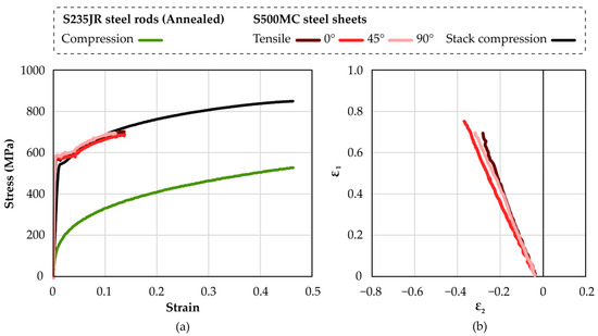
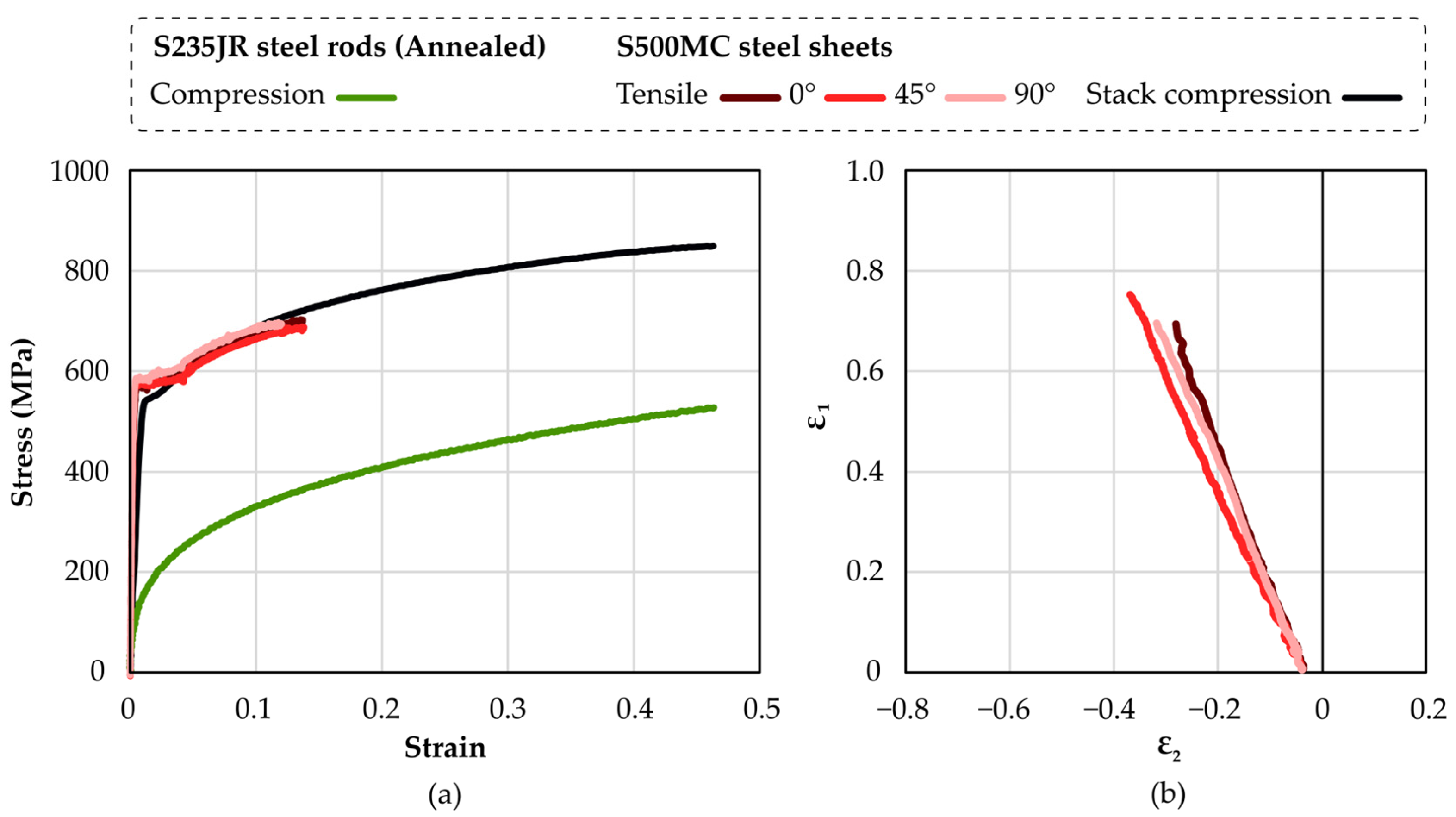
For the S235JR steel, uniaxial compression tests were performed in accordance with the ASTM E9 standard [23], with a height of 10 mm and a diameter of 6 mm. Figure 2a presents the resulting flow curves obtained from uniaxial and stack compression tests performed using an Instron SATEC hydraulic testing machine, as well as tensile tests conducted with an Instron 5900 universal testing machine (Norwood, MA, USA), all at room temperature and quasi-static conditions.
Figure 2.
(a) Flow curves and (b) strain loading paths derived from material characterization tests conducted on S235JR annealed steel rods and S500MC 2 mm sheets.
For tensile tests, the specimen orientation relative to the rolling direction (0°, 45°, and 90°) was considered for both flow curves and strain loading paths, as shown in principal strain space in Figure 2b. These strain loading paths, obtained by digital image correlation (DIC), allowed determining the Lankford coefficients for all three orientations and the resulting anisotropy coefficient from the following equations,
The above equations allowed retrieving the anisotropy coefficient , which is close to the value of an isotropic material. Furthermore, the flow curves for each orientation coincide with those obtained from stack compression tests. Therefore, the S500MC steel sheets can be represented as isotropic in the finite element models presented and described in Section 2.4.
2.2. Experimental Workplan
The HSLA steel lap joints were fabricated using 2 mm thickness S500MC sheets, which were water jetted to dimensions of 150 mm in length and 50 mm in width. For the double-flush riveted joints, S235JR rivets were produced by turning annealed rods of 5 mm diameter with variable height, corresponding to the dimensions of the countersunk holes.
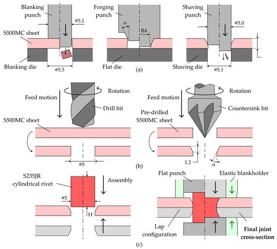
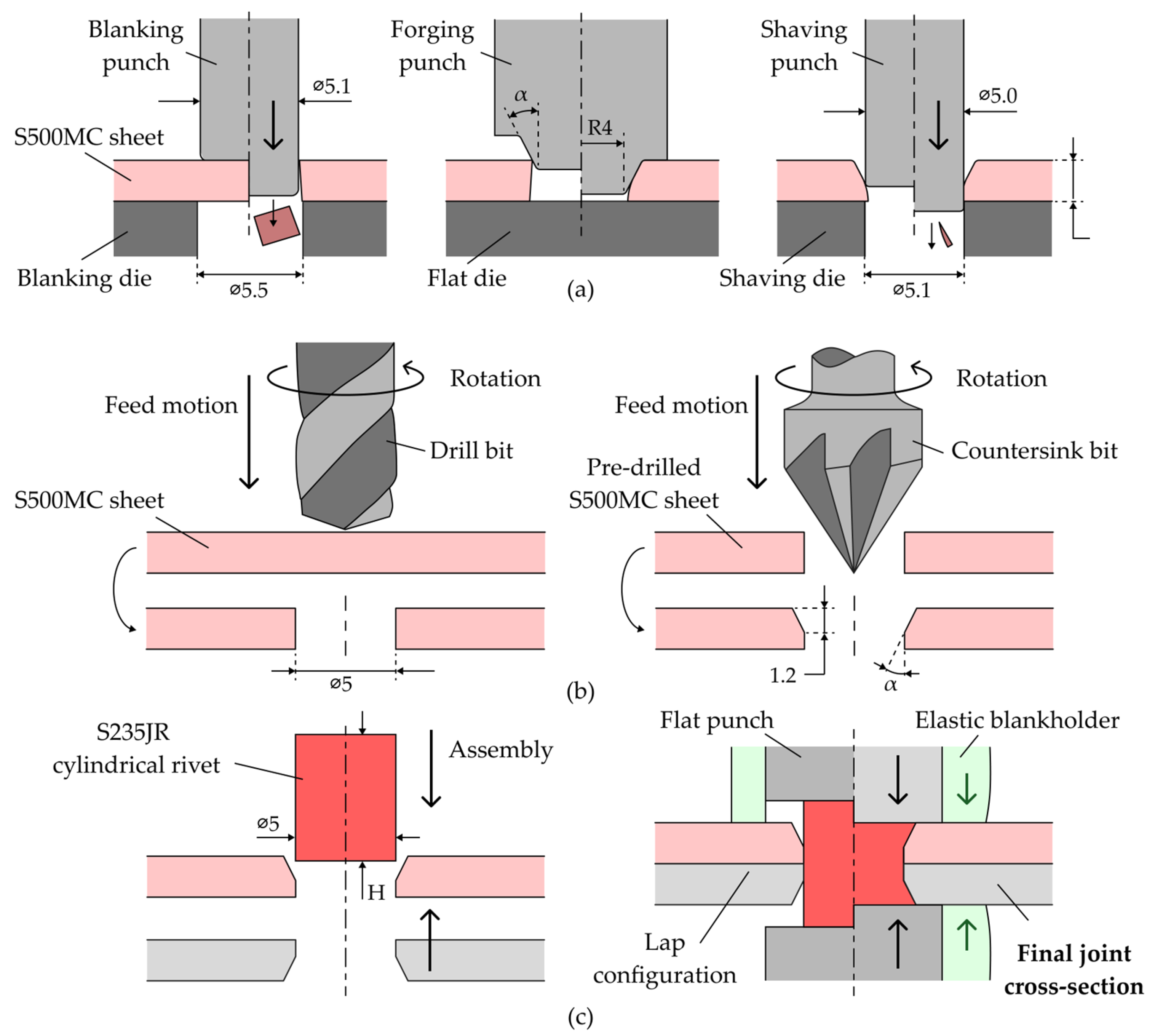
The countersunk holes were produced using the two double-flush riveting variants under investigation. The first variant involved three sequential metal forming operations: (i) punching a cylindrical hole, (ii) forging the hole with a truncated conical punch, and (iii) shaving to calibrate the cylindrical region of the countersunk hole. The second variant employed machining operations to drill countersunk holes with geometries identical to those produced by the first variant. Both fabrication routes are illustrated in Figure 3a and Figure 3b, respectively.
Figure 3.
Schematic representations of the fabrication variants for producing countersunk holes using (a) metal forming and (b) machining, followed by (c) the final double-flush riveting stage. All dimensions are provided in millimeters.
Each fabrication route concludes with a double-flush riveting stage, during which a solid cylindrical rivet is plastically deformed into the countersunk geometries of both holes to join the sheets, as shown in Figure 3c.
The equipment used to create forged holes in the S500MC steel sheets was the same hydraulic testing machine employed for the compression tests (Section 2.1). Punching, forging, and shaving were performed using active tool components manufactured from AISI D3 tool steel and integrated into a progressive tooling system developed by the authors [19]. The machined holes were produced in a MiniMill 2 machining center from HAAS (Oxnard, CA, USA), equipped with 5 mm diameter tungsten carbide twist drills and countersink drill bits with inclination angles of 20°, 30°, and 45°. In the final double-flush riveting stage, both variants used an upsetting tool set comprising two active cylindrical punches with FibroFlex elastomers, which functioned as an elastic blank holder (see Figure 3c).
The experimental work plan for both variants of double-flush riveting focused on the inclination angle of the countersunk holes (refer to Figure 3), which was limited to 30° in the case of forged holes. The height of the rivets was defined as a function of to ensure the incompressibility of the rivet material, resulting in mm for , respectively.
For resistance spot welding, the fabrication tests were performed using a 810X machine from TECNA (Bologna, Italy) coupled with a TE500 control unit operating at 50 Hz. The electrodes were made of electrolytic copper (99.9%) and had a truncated conical geometry with a flat circular face of 8 mm in diameter, in accordance with ISO 5182 [24]. The resistance spot-welded tests were made using different welding currents ranging from 4 kA to 8 kA under a constant welding time of 0.4 s and a constant electrode force of 3.5 KN.
2.3. Characterization Tests
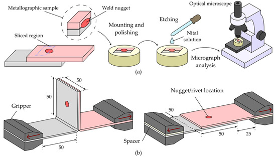
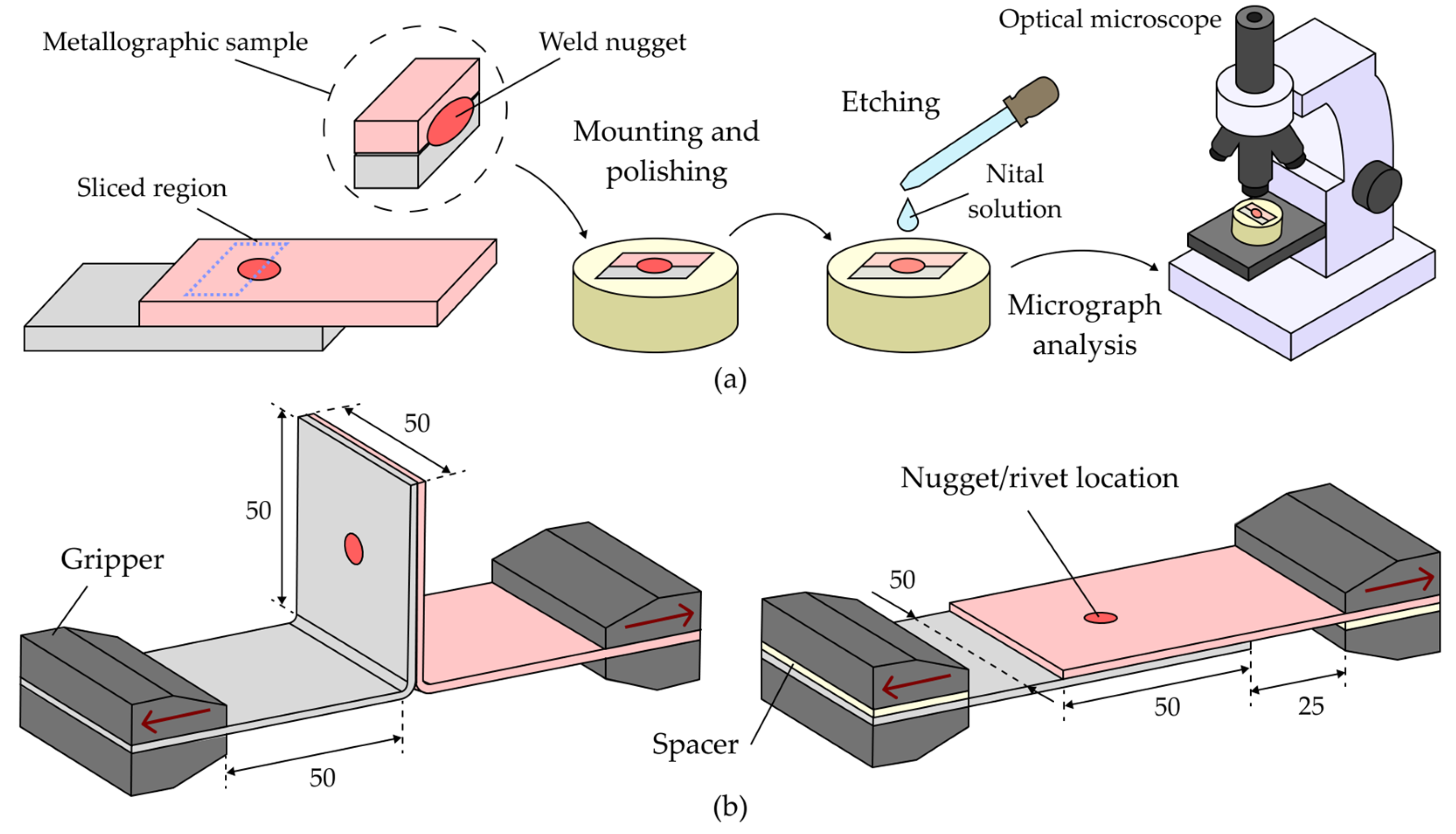
Following the fabrication of double-flush riveted and resistance spot-welded lap joints, a final series of tests was conducted to evaluate the joinability of each process. The tests included micrograph analysis of resistance spot-welded joints and destructive mechanical testing for both joining methods, as illustrated in Figure 4a,b.
Figure 4.
Schematic representations of post-fabrication tests conducted on various joint types, including (a) micrograph analysis and (b) destructive tensile lap-shear (left) and peel (right) mechanical testing.
Microstructural analysis was performed on metallographic samples sectioned from the central region of the resistance spot-welded joints and polished using a diamond suspension with a particle size of 1 μm. The samples were chemically etched by immersion in Nital (5% nitric acid in ethanol) to reveal the microstructure of the joints. The geometries, dimensions, and metallographic characteristics of the joints were subsequently examined using an Olympus DSX2000 digital microscope from Evident (Tokyo, Japan).
Destructive mechanical testing was performed at room temperature using the same universal testing machine described in Section 2.1, operating at a constant crosshead speed of 10 mm/min. The joints were fabricated according to the geometries provided in Figure 4b to facilitate tensile lap-shear and tensile peel tests until failure. Test dimensions were selected in accordance with ISO 14273 for tensile lap-shear tests and ISO 14270 for tensile peel tests [25,26].
2.4. Numerical Modelling
Double-flush riveting was numerically modelled using the in-house finite element computer program i-form [27]. The program utilizes a flow formulation and is constructed on a control volume approach, where velocities serve as the primary unknowns in the following modified weak form of the quasi-static force equilibrium equations,
The first term in (3) makes use of the deviatoric Cauchy stress tensor and the rate of deformation tensor . The second term in (3) makes use of the hydrostatic stress tensor and the volumetric rate of deformation , and is numerically handled through relaxation of the incompressibility condition of the velocity field by making , where is a large positive number.
The third and fourth terms in (3) correspond to the tractions applied on the boundary and to the frictional effects due to material sliding with a relative velocity along the contact interfaces . Friction was modeled with the law of constant friction , where is the friction shear stress, is the friction factor, and is the shear flow stress.
The last term of (3) accounts for the contact between deformable objects and uses a two-pass contact search algorithm, where the contact pairs are extracted from the faces of the finite elements used in the discretization. The symbol denotes the normal gap velocities in the contact pairs, which are penalized by a large number to avoid penetration.
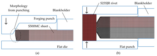
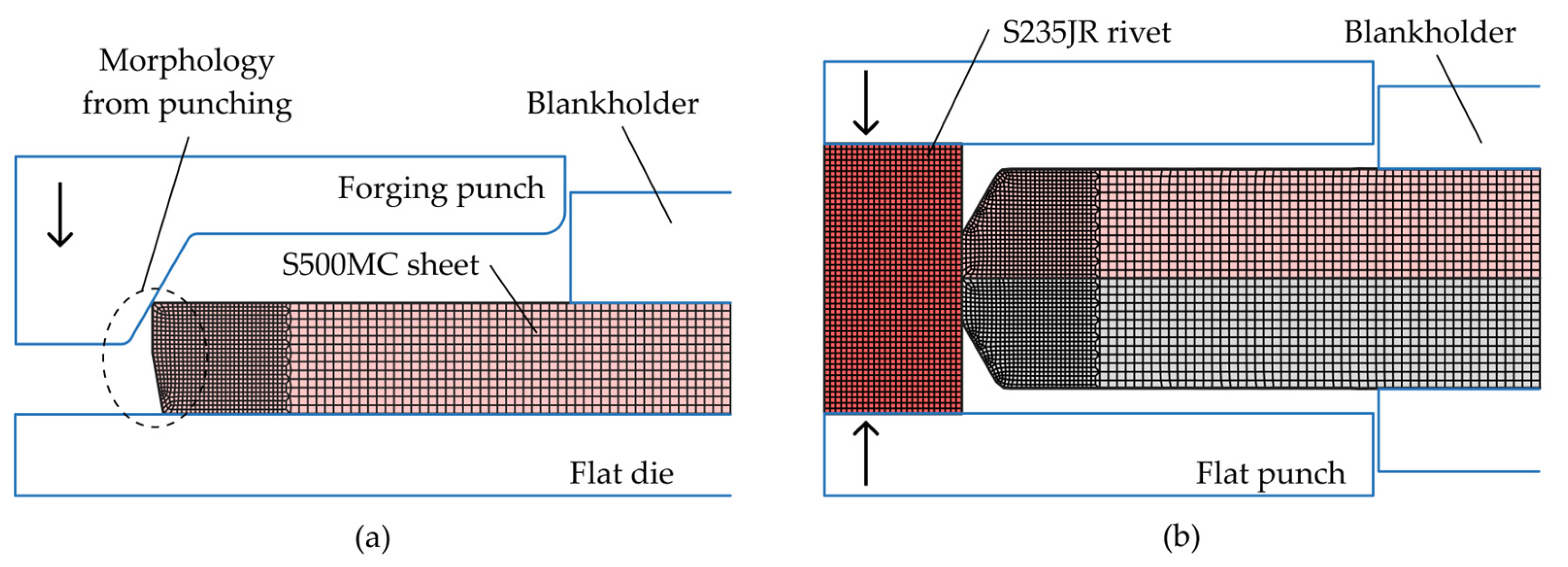
Figure 5a illustrates the rotationally symmetric finite element model employed in the numerical simulation of the forging stage of the double-flush riveting variant that uses forged holes.
Figure 5.
Rotationally symmetric finite element models employed to simulate (a) the forging stage and (b) the joining by forming stage in double-flush riveting with forged holes. Both scenarios correspond to a specific inclination angle .
After forging, the inner diameter of the meshes was trimmed to replicate the post-shaving hole geometry. The meshes were then assembled into the rotationally symmetric finite element model depicted in Figure 5b, which simulated the joining by forming stage of the double-flush riveting process. This stage was also simulated for double-flush riveting with machined holes, assuming a zero-strain field in the S500MC steel sheets before joining.
For all the models, both the sheets and rivets were treated as deformable objects undergoing plastic deformation, and their cross-sections were discretized using quadrilateral elements. The tools were treated as rigid objects, and their contours were discretized using linear contact-friction elements with a constant friction factor , based on the finite element-predicted forces that best matched the experimental measurements.
3. Results and Discussion
3.1. Resistance Spot Welding
The results presented in this section were obtained from experimental tests on resistance spot welding of S500MC steel sheets. The tests were conducted according to the procedures described in Section 2.2 to identify the most suitable parameter set that ensures proper joinability between the two sheets, particularly given that the associated microstructural mechanisms remain insufficiently reported for the resistance spot welding of S500MC steel sheets, in contrast to other fusion welding processes such as laser welding or gas tungsten arc welding. The validity of the results was ensured by performing at least five repetitions for each testing condition.
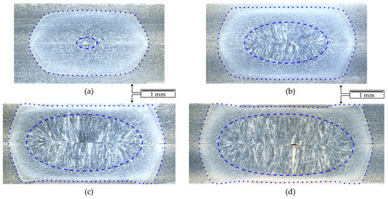
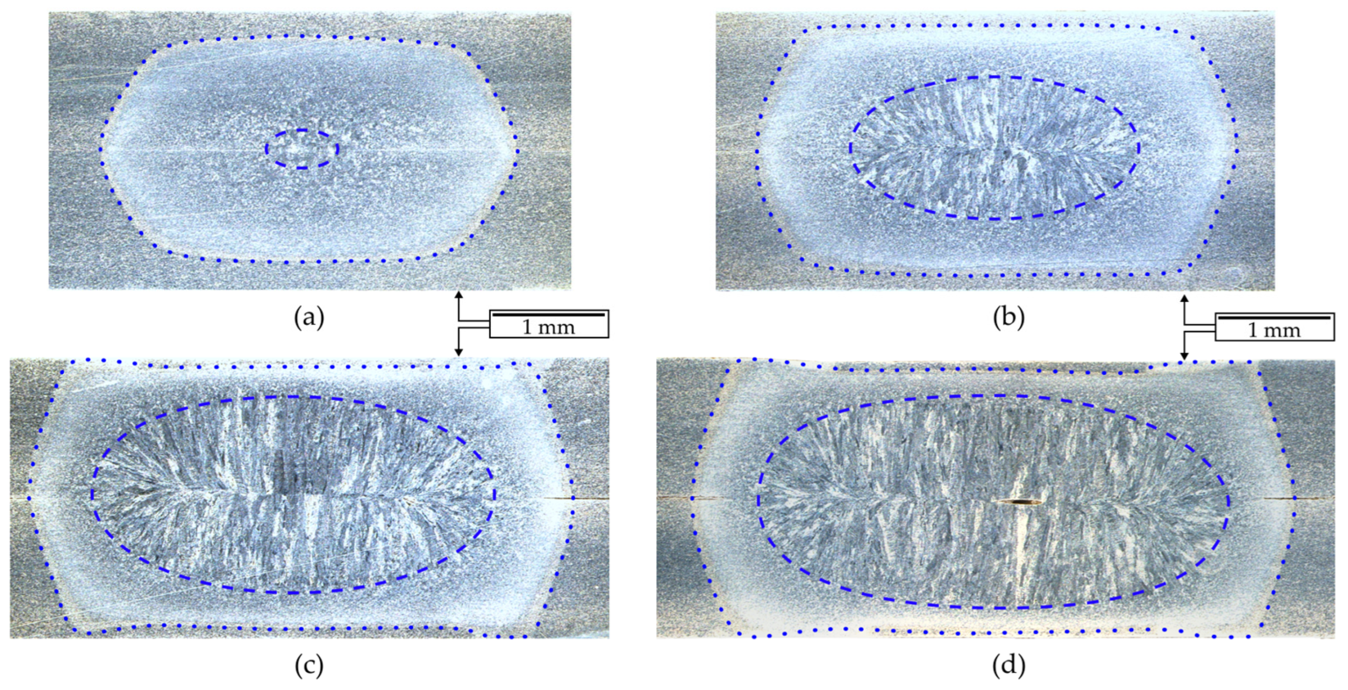
Figure 6 shows the macrostructure revealed by chemical etching of four different joint conditions. These conditions correspond to welding current values ranging from 5 kA to 8 kA and highlight the influence of the applied current on joint formation.
Figure 6.
Macrostructure analysis of resistance spot-welded joints made in S500MC steel sheets with a welding current of (a) , (b) , (c) , and (d) . The blue-dashed line illustrates the weld nugget for each joint condition, while the blue-pointed line represents the interface between the base metal and the heat-affected zone (HAZ).
The case with an electric current kA did not result in weld nugget formation, as the thermal energy generated was insufficient to produce a weld nugget. In comparison, the case with a slightly higher electric current kA, shown in Figure 6a, enabled nugget formation but resulted in a minimal molten volume, producing an average nugget diameter of only 0.726 mm.
Increasing the electric current to kA (Figure 6b) led to a substantial increase of 303% in the average nugget diameter, reaching a value of 2.927 mm, which is primarily attributed to the fusion of the regions occupied by the heat-affected zone of the previous case. Nevertheless, this diameter is still near the minimum required nugget diameter of 2 mm (equal to the sheet thickness), as specified in AWS C1.1M/C1.1:2019 AMD1 by the American Welding Society (AWS) and the Society of Automotive Engineers (SAE) [28,29].
Given the above, further increases in welding current were required, leading to the cases shown in Figure 6c,d, which address the issues identified in the previous conditions. Specifically, a welding current kA gave an average nugget diameter of 4.088 mm, approximately 104.4% above the minimum value specified by the AWS and SAE. Moreover, the volume ratio between the weld nugget and the heat-affected zone (HAZ) is significantly smaller than in previous cases, thereby limiting the extent of grain coarsening in the vicinity of the melted volume.
Further increasing the welding current to kA led to a higher average nugget diameter of 4.484 mm. However, this value is only marginally higher (approximately 14%) than that obtained at 7 kA. This indicates that further increases in welding current do not significantly alter the macrostructure of resistance spot-welded joints and may instead introduce undesirable effects, such as increased sheet warping due to thermally induced stresses generated after welding, excessive columnar grain growth, and the formation of internal pores at the weld center due to shrinkage.
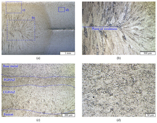
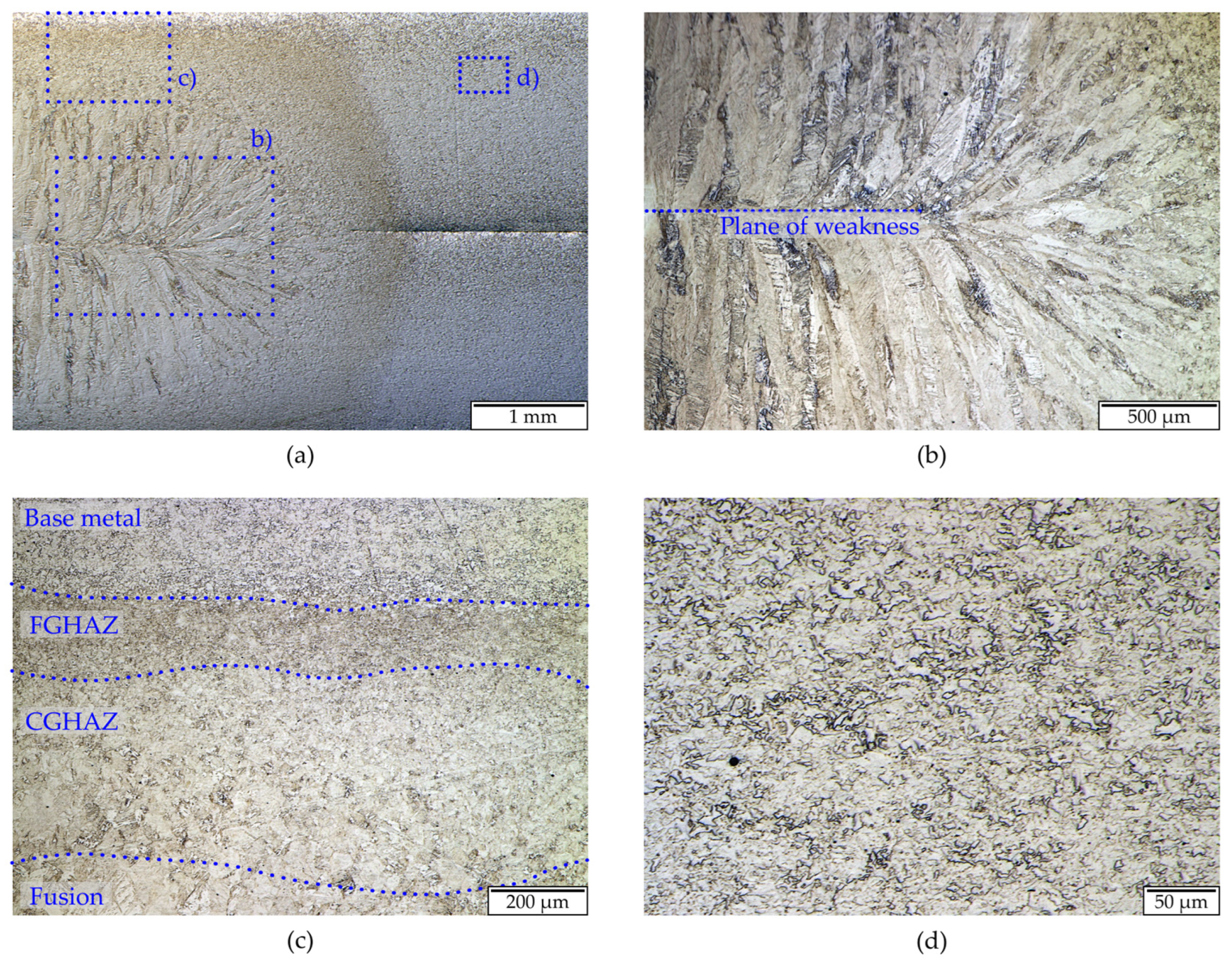
Figure 7 displays the microstructure analysis for the case welded at a welding current kA. From the overall picture shown in Figure 7a, strong microstructural gradients across the weld are evident, as expected for a fusion-welded HSLA steel [30].
Figure 7.
Microstructural analysis of resistance spot-welded joints in S500MC steel sheets at a specified welding current kA, highlighting the: (a) overall metallographic regions, (b) fusion zone, (c) transition regions to the HAZ, and (d) base metal.
The magnification shown in Figure 7b reveals the columnar grain growth occurring within the fusion zone of the joint, where the weld nugget is formed. This microstructure develops during solidification, as columnar grains grow from the fusion boundary toward the weld centre and impinge along the sheet-to-sheet faying interface, resulting in a cast-like solidification structure. The impingement of these grains leads to the formation of a ‘plane of weakness’ within the nugget, as indicated by the blue dashed line in Figure 7b.
The microstructural transition from the fusion zone to the base metal across the HAZ is shown in Figure 7c. Adjacent to the fusion boundary, the coarse-grained heat-affected zone (CGHAZ) is characterized by prior-austenite grain growth and the formation of hard martensitic microstructures due to the limited ability to rapidly dissipate the heat transferred from the fusion boundaries [31]. With increasing distance from the weld centre, the microstructure refines within the fine-grained heat-affected zone (FGHAZ), where finer bainitic and ferritic transformation products are observed, before gradually transitioning into the uniform fine-grained ferritic microstructure of the base metal typical of HSLA S500MC steel. This is evidenced by the higher magnification shown in Figure 7d and is responsible for the excellent cold ductility of S500MC steel [32].
Therefore, considering the balance between achieving a sufficiently large nugget diameter and minimizing adverse effects such as sheet warping, excessive grain coarsening, and internal porosity, a welding current kA provides the optimal welding condition for the subsequent tests presented in Section 3.3.
3.2. Double-Flush Riveting
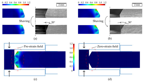
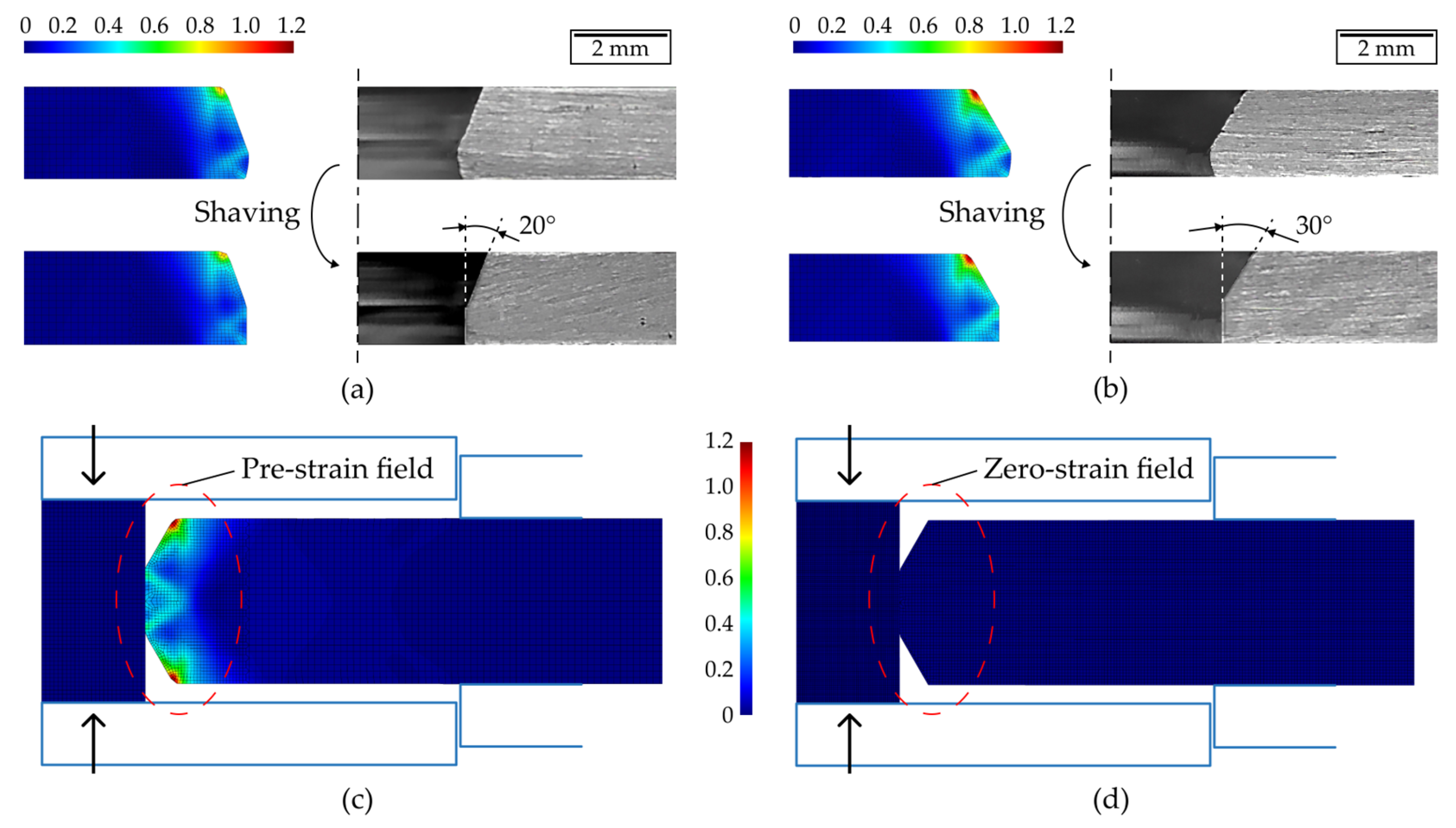
Joining by forming via double-flush riveting was initially analysed in terms of the fabrication of countersunk holes using the two process variants under investigation. Figure 8a,b first present results for the variant involving a forging operation with truncated conical punches at 20° and 30° inclination angles. The figures include finite element distributions of the effective strain, along with the corresponding cross-sections of the sheets at the end of both the forging and shaving stages.
Figure 8.
Finite element distributions and experimental cross-sections obtained at the end of the forging and shaving stages for inclination angles of (a) 20° and (b) 30°. (c,d) show the assembled finite element models for the double-flush riveting stage with forged and machined countersunk holes, respectively, with an inclination angle .
Figure 8a,b demonstrate that the forging operation achieves the intended inclination of the conical region of the countersunk holes but produces a non-homogeneous geometry along the cylindrical region. This non-uniformity primarily results from frictional sliding at the interfaces with the active tool components. Consequently, the subsequent shaving stage is necessary to calibrate the cylindrical region of the holes to the prescribed 5 mm diameter.
The strong agreement between the finite element meshes and the experimental cross-sections in Figure 8a,b supports the use of these meshes for simulating the double-flush riveting stage. In this simulation, the two sheets and the corresponding rivet material are overlapped, as illustrated in Figure 8c for a representative inclination angle , and the effective strain resulting from the forging stage is retained and incorporated into the following joining by forming simulations. In contrast, the simulations of double-flush riveting with machined holes, shown in Figure 8d, use models constructed entirely from scratch, without accounting for pre-existing strain in both the sheet and rivet materials.
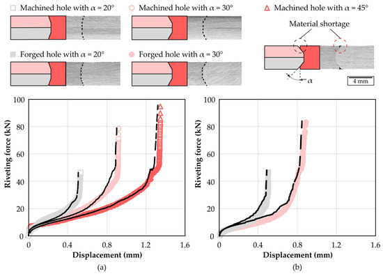
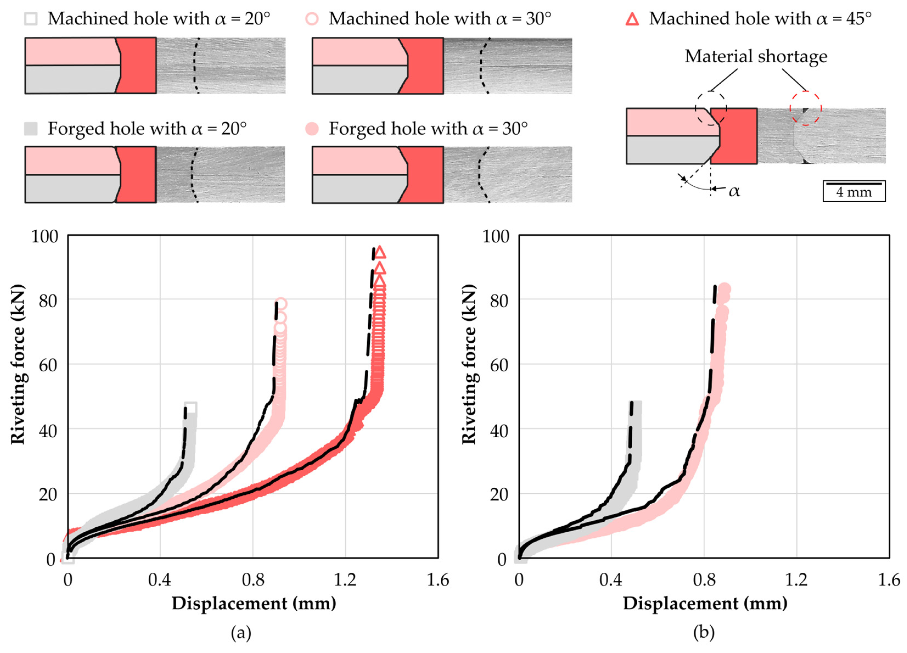
Figure 9a,b present both the experimental and finite element-predicted force–displacement curves for double-flush riveting tests conducted with machined and forged holes. For forged holes, results were obtained at countersunk inclination angles of ° and °, since the ° inclination angle was excluded to avoid excessive sheet bending. In contrast, machined countersunk holes do not exhibit this limitation, allowing for an inclination angle of °.
Figure 9.
Experimental and finite element-predicted (refer to the black lines) force–displacement curves for double-flush riveting using (a) machined holes and (b) forged holes. The corresponding experimental and finite element-predicted cross-sections of the joints are also included.
As observed, the riveting force increases with an increasing inclination angle, since a larger rivet volume must be plastically deformed to obtain joints without protrusions. Overall, the force–displacement profiles exhibit a gradual increase with displacement, followed by a steep rise in the final stages of double-flush riveting due to material incompressibility. Nevertheless, the maximum riveting forces remain below 100 kN, which can be achieved under conventional press-tool systems.
When comparing the two variants at inclination angles of ° and °, the final forces are slightly higher for forged holes due to the sheet material’s prior strain hardening. However, the experimental cross-sections shown at the top of Figure 9 are similar for both variants, suggesting that, from a design perspective, the use of either machined or forged holes results in comparable performance. This observation is further supported by the finite element-predicted cross-sections at the end of the double-flush riveting stage, which show good agreement with the experimental results, as well as by the same accurate prediction of the force–displacement curves. This agreement allows concluding that all assumptions assumed in the employed finite element models (refer to Section 2.4) reliably represent both variants of double-flush riveting under analysis.
Finally, the use of machined countersunk holes inclined at ° also allows the formation of a permanent mechanical joint free of protrusions. However, as shown by both the experimental and finite element–predicted cross-sections at the end of riveting, the resulting joints exhibit material shortage due to insufficient filling of the rivet material along the machined holes (refer to Figure 9). This behaviour is associated with a more pronounced radial expansion of the rivet material against both S500MC sheets, resulting in the expansion of the corresponding countersunk hole which, consequently, reduces the interlock distance. Considering this reduction in interlock quality, double-flush riveted joints with an inclination angle of 45° were excluded from further analysis.
3.3. Mechanical Testing
The mechanical performance of the S500MC steel lap joints was evaluated through mechanical testing, based on the most representative results discussed in the previous sections. The investigated configurations included conventional joints produced by resistance spot welding using an electric current kA and a welding time of 0.4 s, as well as the newly proposed joints obtained by the two variants of double-flush riveting with machined or forged countersunk holes and inclination angles ° and °. This enabled the production of joints with welding nuggets and plastically deformed rivets of comparable size, thus allowing for a close comparison between both joining processes.
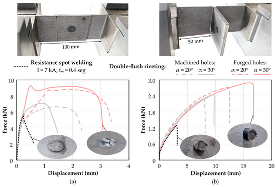
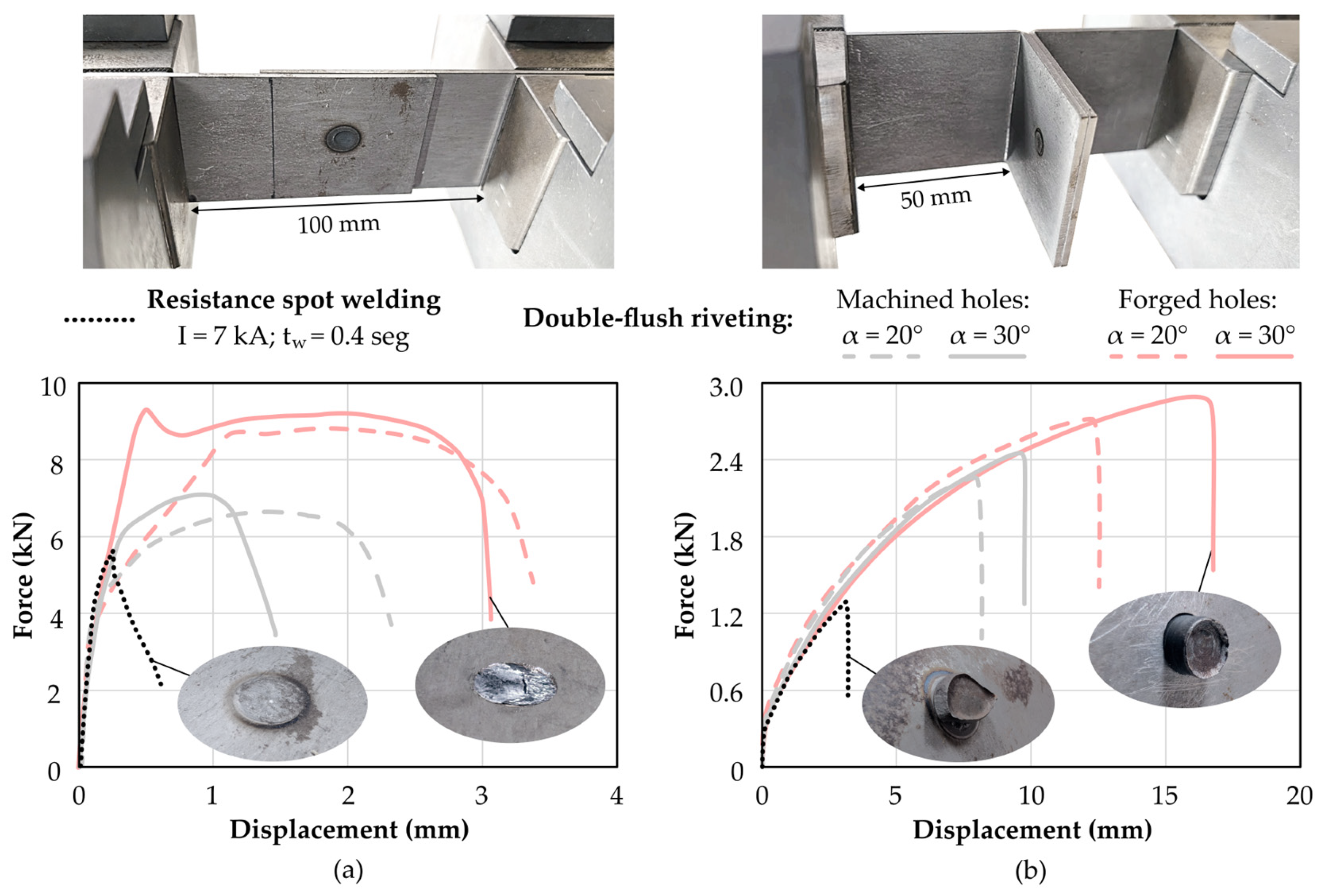
The results are presented in Figure 10a,b as force–displacement curves obtained from destructive lap-shear and peel tests performed on the previously mentioned universal testing machine. Each curve represents the average of at least five repetitions per test, with the deviations in maximum force and displacement at peak, relative to the corresponding mean values, remaining below 8% for both double-flush riveted and resistance spot-welded joints.
Figure 10.
Destructive force–displacement curves obtained from (a) tensile lap-shear and (b) peel tests carried out on resistance spot-welded and double-flush riveted lap joints.
From the analysis of the graphs in Figure 10, it can be concluded that double-flush riveted joints, obtained with machined or forged holes, achieve higher maximum loads in both types of destructive tests than resistance spot-welded joints. This behaviour is attributed to the inherent thermal input of fusion welding processes such as resistance spot welding, which generates regions with irregular microstructures composed of grains of varying sizes, as previously disclosed in Section 3.1. In contrast, these microstructural features do not occur in double-flush riveted joints because they are fabricated at room temperature, preserving the original uniform fine-grained ferritic microstructure of the S500MC sheet material (refer to Figure 7d).
A similar trend is observed when analyzing the displacement at maximum load. Double-flush riveted joints consistently exhibit higher displacement values at maximum load compared to resistance spot-welded joints for both types of destructive tests. This indicates greater load-carrying capacity and improved deformation capability prior to failure. As with the peak force results, the differences in displacement at peak between the various joint types are significantly larger than the deviations observed between repeated tests of the same configuration, ensuring repeatability of the obtained results.
Adding to the above, double-flush riveted joints with an inclination angle of ° exhibit better mechanical performance than those with °. This increase is related to the creation of a higher mechanical interlock, which directly affects the maximum load the joints can sustain before failure for both types of destructive tests.
Lastly, the results also demonstrate that double-flush riveted joints with forged holes exhibit higher maximum destructive forces compared to those with machined holes. This increase in strength does not alter the failure modes, which remain characterized by rivet slicing in tensile lap-shear tests and rivet detachment in peel tests, analogous to the interfacial and pull-out failures observed in resistance spot-welded joints (refer to the close-up images in Figure 10). However, the improved performance is clearly reflected in the force–displacement curves and is attributed to strain hardening of the S500MC sheet material. This finding is consistent with the results presented in Section 3.2, where a significant effective strain field was identified as a result of the forging process used to form the conical region of the countersunk holes, thereby enhancing the load-bearing capacity of double-flush riveted joints with forged holes.
4. Conclusions
The principal conclusions from the investigation of joinability and performance between double-flush riveted and resistance-welded lap joints in high-strength low-alloy steels (HSLA) are the following:
- Resistance spot-welded joints exhibit microstructural features similar to those reported in the literature for electric arc- or laser-welded joints produced in comparable steel alloys. Although the scale of these features can be adjusted through process parameters, the microstructure of the joints remains predominantly heterogeneous, with grain growth occurring along the interface between the fusion zone and the heat-affected zone.
- Double-flush riveted joints with machined or forged countersunk holes present nearly identical cross-sectional geometries. Nevertheless, joints produced with machined countersunk holes are easier to fabricate, as they rely on simpler and widely available cutting tools rather than part-dependent progressive tooling systems required for producing forged countersunk holes. This makes the machined-hole variant more suitable for low- to medium-batch production.
- The interlock distance depends on the inclination angle of the countersunk holes, which explains its direct relationship with the improved mechanical performance observed in both tensile lap-shear and peel tests. However, the interlock distance may be limited when excessively high inclinations are used, due to a shortage of rivet material to fully fill the countersunk holes.
- The creation of forged holes inevitably generates an effective strain field, which in turn requires higher riveting forces to produce joints without protrusions. However, strain hardening enhances the mechanical performance of double-flush riveted joints, making this variant particularly relevant for load-bearing applications.
- Regardless of the inclination angle or the double-flush riveting variant, the mechanical performance of the resulting joints was consistently superior to that of resistance spot-welded joints when both nuggets and rivets were of equivalent size. This demonstrates that double-flush riveting is a viable solution for joining relatively thin, load-bearing steel sheets and enables future applications involving dissimilar materials.
Author Contributions
Conceptualization, J.P.M.P. and C.M.A.S.; methodology, R.F.V.S., J.P.M.P. and C.M.A.S.; software, R.F.V.S. and P.A.F.M.; validation, I.M.F.B.; formal analysis, R.F.V.S. and I.M.F.B.; investigation, R.F.V.S., J.P.M.P., I.M.F.B., C.M.A.S. and P.A.F.M.; resources, J.P.M.P. and C.M.A.S.; data curation, R.F.V.S.; writing—original draft preparation, J.P.M.P.; writing—review and editing, R.F.V.S., I.M.F.B., C.M.A.S. and P.A.F.M.; visualization, I.M.F.B. and J.P.M.P.; supervision, I.M.F.B. and C.M.A.S.; project administration, J.P.M.P. and P.A.F.M.; funding acquisition, P.A.F.M. All authors have read and agreed to the published version of the manuscript.
Funding
This research was funded by Fundação para a Ciência e a Tecnologia of Portugal and IDMEC via LAETA (project https://doi.org/10.54499/UID/50022/2025) and by the Innovation Pact “R2UTechnologies—modular systems” (C644876810-00000019), by the “R2UTechnologies” Consortium, co-financed by NextGeneration EU, through the Incentive System “Agendas para a Inovação Empresarial” (“Agendas for Business Innovation”), within the Recovery and Resilience Plan (PRR).
Data Availability Statement
All data supporting the reported results are available in this paper.
Acknowledgments
The authors would like to acknowledge the support provided by Fundação para a Ciência e a Tecnologia of Portugal (FCT) and IDMEC for their financial support via LAETA (project https://doi.org/10.54499/UID/50022/2025). This work is a result of the Innovation Pact “R2UTechnologies—modular systems” (C644876810-00000019), by the “R2UTechnologies” Consortium, co-financed by NextGeneration EU, through the Incentive System “Agendas para a Inovação Empresarial” (“Agendas for Business Innovation”), within the Recovery and Resilience Plan (PRR). The support from the company MCG—Mind for Metal is also acknowledged.
Conflicts of Interest
The authors declare no conflicts of interest.
References
- Kuziak, R.; Kawalla, R.; Waengler, S. Advanced High Strength Steels for Automotive Industry. Arch. Civ. Mech. Eng. 2008, 8, 103–117. [Google Scholar] [CrossRef] [Scilit]
- Kumar, S.; Singhai, M.; Desai, R.; Sam, S.; Patra, P.K. Development of Advanced High Strength Steel for Improved Vehicle Safety, Fuel Efficiency and CO2 Emission. J. Inst. Eng. India Ser. D 2016, 97, 153–158. [Google Scholar] [CrossRef] [Scilit]
- Uchihara, M. Joining Technologies for Automotive Steel Sheets. Weld. Int. 2011, 25, 249–259. [Google Scholar] [CrossRef] [Scilit]
- Zeidi, A.; Akrout, M.; Elleuch, K.; Pereira, A. Reducing Maximum Punching Force in Sheet Cold Forming: A Numerical Study of a New Punch Design (Part I). Metals 2025, 15, 1338. [Google Scholar] [CrossRef] [Scilit]
- Habibi, N.; Ramazani, A.; Sundararaghavan, V.; Prahl, U. Failure Predictions of DP600 Steel Sheets Using Various Uncoupled Fracture Criteria. Eng. Fract. Mech. 2018, 190, 367–381. [Google Scholar] [CrossRef] [Scilit]
- Perka, A.K.; John, M.; Kuruveri, U.B.; Menezes, P.L. Advanced High-Strength Steels for Automotive Applications: Arc and Laser Welding Process, Properties, and Challenges. Metals 2022, 12, 1051. [Google Scholar] [CrossRef] [Scilit]
- Bian, J.; Mohrbacher, H.; Zhang, J.-S.; Zhao, Y.-T.; Lu, H.-Z.; Dong, H. Application Potential of High Performance Steels for Weight Reduction and Efficiency Increase in Commercial Vehicles. Adv. Manuf. 2015, 3, 27–36. [Google Scholar] [CrossRef] [Scilit]
- Banerjee, K. Improving Weldability of an Advanced High Strength Steel by Design of Base Metal Microstructure. J. Mater. Process. Technol. 2016, 229, 596–608. [Google Scholar] [CrossRef] [Scilit]
- Saha, D.C.; Westerbaan, D.; Nayak, S.S.; Biro, E.; Gerlich, A.P.; Zhou, Y. Microstructure-Properties Correlation in Fiber Laser Welding of Dual-Phase and HSLA Steels. Mater. Sci. Eng. A 2014, 607, 445–453. [Google Scholar] [CrossRef] [Scilit]
- Meschut, G.; Janzen, V.; Olfermann, T. Innovative and Highly Productive Joining Technologies for Multi-Material Lightweight Car Body Structures. J. Mater. Eng. Perform. 2014, 23, 1515–1523. [Google Scholar] [CrossRef] [Scilit]
- Alfano, M.; Morano, C.; Moroni, F.; Musiari, F.; Danilo Spennacchio, G.; Di Lonardo, D. Fracture Toughness of Structural Adhesives for the Automotive Industry. Procedia Struct. Integr. 2018, 8, 561–565. [Google Scholar] [CrossRef] [Scilit]
- Weber, G.; Thommes, H.; Gaul, H.; Hahn, O.; Rethmeier, M. Mechanical Properties of Weldbonded Joints of Advanced High Strength Steels. J. Adhes. Sci. Technol. 2011, 25, 2369–2407. [Google Scholar] [CrossRef] [Scilit]
- Pragana, J.P.M.; Sampaio, R.F.V.; Bragança, I.M.F.; Silva, C.M.A.; Martins, P.A.F. Injection Lap Riveting of Aluminum Busbars—A Thermo-Electro-Mechanical Investigation. J. Manuf. Mater. Process. 2022, 6, 74. [Google Scholar] [CrossRef] [Scilit]
- Mori, K.; Abe, Y. A Review on Mechanical Joining of Aluminium and High Strength Steel Sheets by Plastic Deformation. Int. J. Lightweight Mater. Manuf. 2018, 1, 1–11. [Google Scholar] [CrossRef] [Scilit]
- Contreiras, T.R.M.; Pragana, J.P.M.; Bragança, I.M.F.; Silva, C.M.A.; Alves, L.M.; Martins, P.A.F. Joining by Forming of Lightweight Sandwich Composite Panels. Procedia Manuf. 2019, 29, 288–295. [Google Scholar] [CrossRef] [Scilit]
- Kasaei, M.M.; Beygi, R.; Carbas, R.J.C.; Marques, E.A.S.; Da Silva, L.F.M. A Review on Mechanical and Metallurgical Joining by Plastic Deformation. Discov. Mech. Eng. 2023, 2, 5. [Google Scholar] [CrossRef] [Scilit]
- Ang, H.Q. An Overview of Self-Piercing Riveting Process with Focus on Joint Failures, Corrosion Issues and Optimisation Techniques. Chin. J. Mech. Eng. 2021, 34, 2. [Google Scholar] [CrossRef] [Scilit]
- Sampaio, R.F.V.; Larue, P.; Pragana, J.P.M.; Bragança, I.M.F.; Silva, C.M.A.; Martins, P.A.F. Double-Flush Riveting by Punching and Compression. J. Adv. Join. Process. 2023, 8, 100155. [Google Scholar] [CrossRef] [Scilit]
- Silva, C.M.A.; Pragana, J.P.M.; Sampaio, R.F.V.; Bragança, I.M.F.; Martins, P.A.F. Advanced Double-Flush Riveting for Multistage Forming Tools. CIRP Ann. 2025, 74, 399–403. [Google Scholar] [CrossRef] [Scilit]
- Molitor, D.A.; Kokozinski, A.; Kubik, C.; Arne, V.; Veitenheimer, C.; Georgi, F.; Krämer, R.; Groche, P. Identifying Productivity-Limiting Factors in Progressive Die Stamping: Data-Driven Methodology for Process Optimization. Prod. Eng. 2025, 19, 575–587. [Google Scholar] [CrossRef] [Scilit]
- Farioli, D.; Kaya, E.; Fumagalli, A.; Cattaneo, P.; Strano, M. A Data-Based Tool Failure Prevention Approach in Progressive Die Stamping. J. Manuf. Mater. Process. 2023, 7, 92. [Google Scholar] [CrossRef] [Scilit]
- ASTM E8/E8M-22; Standard Test Methods for Tension Testing of Metallic Materials. ASTM International: West Conshohocken, PA, USA, 2024.
- ASTM E9; Test Methods of Compression Testing of Metallic Materials at Room Temperature. E28 Committee ASTM International: West Conshohocken, PA, USA, 2010.
- ISO 5182:2016; Resistance Welding—Materials for Electrodes and Ancillary Equipment. ISO: Geneva, Switzerland, 2016.
- ISO 14273:2016; Resistance Welding—Destructive Testing of Welds—Specimen Dimensions and Procedure for Tensile Shear Testing Resistance Spot and Embossed Projection Welds. ISO: Geneva, Switzerland, 2016.
- ISO 14270:2016; Resistance Welding—Destructive Testing of Welds—Specimen Dimensions and Procedure for Mechanized Peel Testing Resistance Spot, Seam and Embossed Projection Welds. ISO: Geneva, Switzerland, 2016.
- Nielsen, C.V.; Martins, P.A.F. Finite Element Flow Formulation. In Metal Forming; Elsevier: Amsterdam, The Netherlands, 2021; pp. 181–249. ISBN 978-0-323-85255-5. [Google Scholar]
- AWS C1.1M/C1.1:2019-AMD1; Recommended Practices for Resistance Welding. AWS: Miami, FL, USA, 2019.
- Barros, M.R.F.; Rosado, P.M.S.; Sampaio, R.F.V.; Pragana, J.P.M.; Bragança, I.M.F.; Silva, C.M.A.; Martins, P.A.F. Exploring the Hybridization of Wire-Arc Additive Manufacturing and Resistance Spot Welding. J. Adv. Join. Process. 2025, 12, 100354. [Google Scholar] [CrossRef] [Scilit]
- Meiabadi, S.; Nematzadeh, F.; Kornokar, K.; Mostaan, H.; ShamsBorhan, M.; Khandan, R.; Demers, V.; Lawrence, J.; Moradi, M. Contrasting the Mechanical and Metallurgical Properties of Laser Welded and Gas Tungsten Arc Welded S500MC Steel. Weld. World 2023, 67, 2215–2224. [Google Scholar] [CrossRef] [Scilit]
- Moradi, M.; Kornokar, K.; Nematzadeh, F.; Mostaan, H.; Meiabadi, S.; Demers, V.; Lawrence, J. Microstructural and Mechanical Investigation on Fiber Laser Welding of S500MC Steel. Sādhanā 2023, 48, 32. [Google Scholar] [CrossRef] [Scilit]
- Payà, A.; Lara, A.; Frómeta, D.; Marés, M.; Gil, I.; Arenillas, C. Effect of Pre-Strain on Edge Formability of High Strength Steels for Chassis Applications. IOP Conf. Ser. Mater. Sci. Eng. 2023, 1284, 012025. [Google Scholar] [CrossRef] [Scilit]
Disclaimer/Publisher’s Note: The statements, opinions and data contained in all publications are solely those of the individual author(s) and contributor(s) and not of MDPI and/or the editor(s). MDPI and/or the editor(s) disclaim responsibility for any injury to people or property resulting from any ideas, methods, instructions or products referred to in the content. |
© 2026 by the authors. Licensee MDPI, Basel, Switzerland. This article is an open access article distributed under the terms and conditions of the Creative Commons Attribution (CC BY) license.