


Abstract
The cutting temperature is an important aspect of the cutting process, and various methods have been devised to measure it. However, most previous studies have focused on the rake-face temperature since the highest temperature is generally observed near the cutting edge on the rake face. On the other hand, tool life and surface quality are strongly related to flank wear; therefore, the flank-face temperature is also of considerable practical importance. This study proposes a method that combines an electrically insulating layer with the tool–workpiece thermocouple method. By placing the insulating layer on the rake face or flank face, the flank-face or rake-face temperature can be measured directly and independently. The proposed method is first validated in the cutting of brass by comparing the rake-face, flank-face, and dual-face temperatures. The method is then applied to the cutting of medium carbon steel to investigate the evolution of the flank-face temperature during flank-wear progression. The results support the feasibility of directly and independently measuring the apparent average temperatures of the flank and rake faces and demonstrate that the measured flank-face temperature increases with flank wear.
1. Introduction
The cutting temperature is an important aspect of the cutting process. For example, the shear deformation, chip–rake friction, and workpiece–flank friction generate heat [1,2,3,4,5], and understanding this temperature leads to understanding the cutting process itself [6]. In addition, various phenomena, such as the thermal deformation, chip morphology, surface quality, and tool wear, are affected directly by the temperature [7]. Hence, various studies have been conducted in the literature to measure the cutting temperature, such as the tool–workpiece thermocouple method [8,9], infrared photographic technique [10], and thin-film thermocouples deposited on the rake face [11,12], as well as thermocouples embedded in the rake face [13]. Owing to these methods, the fundamentals of the cutting process have been revealed to some extent and led to the development of various technologies, such as cutting tools, machine tools, coolants, etc.
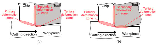
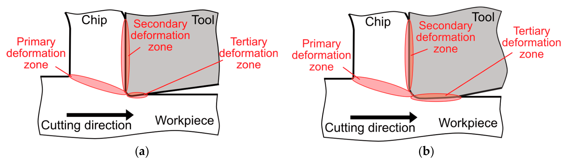
Meanwhile, most previous studies have focused on the rake-face temperature, since the highest temperature is generally observed near the cutting edge on the rake face [14]. However, the flank-face temperature is also of considerable practical importance. Tool life is commonly determined by the flank-wear width, as the flank wear directly affects surface finish, surface integrity, and dimensional accuracy. Figure 1 illustrates the heat generation in the cutting process for both (a) the initial cutting-edge state and (b) the worn state. As flank wear progresses, increased contact between the flank face and the machined surface enhances ploughing and friction, leading to the deterioration of the generated surface and increased heat generation at the flank face. Therefore, the flank-face temperature becomes increasingly important for understanding the thermal phenomena associated with flank wear and surface generation.
Figure 1.
Heat generation in (a) the initial cutting-edge state and (b) worn state.
Although the flank-face temperature is of considerable importance, only a limited number of studies have investigated it. Several approaches have been proposed to estimate or measure the temperature associated with the flank face. For example, the chip-surface temperature measured by infrared thermography was reported to increase with increasing flank-wear width [15]. Heat flux acting on the flank face was estimated by solving an inverse heat-conduction problem using temperatures measured in the tool holder [16]. A two-color pyrometer has also been used to measure the tool temperature, predominantly on the flank face, immediately after cutting by receiving infrared radiation from the tool through an optical fiber embedded in the workpiece [17]. In addition, a representative temperature at the midpoint of an artificially ground region of wear was measured using a thermocouple formed between the workpiece and a platinum wire embedded in the tool [18]. A more direct approach was proposed using a thermocouple junction formed between the flank face and a fine metal wire embedded in the workpiece that were cut together with it [19]. Nevertheless, the measured signal may be influenced by junctions formed at locations other than the flank face, limiting the measurement accuracy. More recently, Volke et al. [20] also reported pyrometric measurements of the rake-face and flank-face temperatures. Although such measurements provide localized temperature information, they require optical access to the measurement region, and the measured temperature should depend on the measurement’s spot size and its exact location, particularly when the spot size is comparable to the flank-wear width. In addition, these measurements do not directly provide the apparent average temperature over the entire tool–workpiece contact area. Therefore, to the best of the authors’ knowledge, no method has yet been established for directly and independently measuring the apparent average flank-face temperature over the entire tool–workpiece contact area. Consequently, the evolution of flank-face temperature during actual flank-wear progression has not yet been sufficiently clarified. Furthermore, despite the practical importance of flank wear, little information is available regarding the evolution of flank-face temperatures during actual wear progression in the cutting process.
In this study, a method is proposed for the direct and independent measurement of rake-face and flank-face temperatures by combining an electrically insulating layer with the tool–workpiece thermocouple method. In the conventional tool–workpiece thermocouple method, the temperature is not distinguished between the two faces, and only an apparent average temperature over the entire contact area is obtained [10]. In the proposed method, the insulating layer is placed on the rake or flank face so that the flank-face or rake-face temperature can be measured directly and independently, respectively. First, the flank-face, rake-face, and dual-face temperatures are measured in the cutting of brass to verify the validity of the proposed method. Second, the proposed method is applied to investigate how the flank-face temperature changes as flank wear progresses in the cutting of medium carbon steel. The results demonstrate that the flank-face and rake-face temperatures can be measured directly and independently, and that the flank-face temperature increases as flank wear progresses.
2. Principle and Experimental Procedures of the Independent Temperature Measurement Method Using an Insulating Layer
2.1. Principle of the Conventional Tool–Workpiece Thermocouple Method
In the tool–workpiece thermocouple method, the tool and workpiece, which are made of dissimilar materials, are regarded as a form of thermocouple. During cutting, a thermoelectromotive force is generated at the tool–workpiece interface, and it is converted into temperature based on a predetermined calibration relationship.
The measured temperature represents an apparent average over the electrically conductive contact area (i.e., the rake face and flank face). Since the contributions from both faces are mixed and cannot be separated, the rake-face and flank-face temperatures cannot be measured independently by this method. Hereafter, this temperature is referred to as the dual-face temperature. However, for understanding temperature-dependent phenomena such as tool wear, it is important to evaluate the temperature of the relevant face, e.g., the rake-face temperature for crater wear and the flank-face temperature for flank wear.
2.2. Proposed Method Using an Insulating Layer
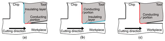
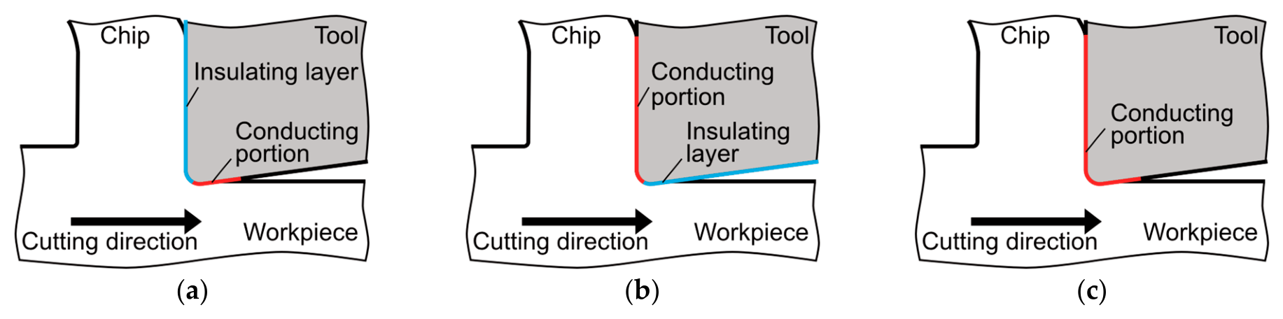
To obtain the flank-face and rake-face temperatures independently, an electrically insulating layer is combined with the tool–workpiece thermocouple method. Schematics of the proposed method are shown in Figure 2. The face on which the insulating layer is placed is electrically insulated, so that the thermoelectromotive force is generated only at the other contact face and represents the temperature of that face; the temperature of each face can then be measured independently and directly.
Figure 2.
Schematics of the proposed method to measure (a) the flank-face temperature and (b) rake-face temperature, and (c) the conventional method to measure the dual-face temperature.
Figure 2 shows schematics of both the proposed method and the conventional method. The flank-face temperature is obtained by placing the insulating layer on the rake face (Figure 2a), and the rake-face temperature is obtained by placing it on the flank face (Figure 2b). The dual-face temperature is obtained using the tool without the insulating layer (Figure 2c). Each of these temperatures is an apparent average temperature over the contact area of the corresponding faces: the flank face, the rake face, and both faces.
2.3. Experimental Setup and Conditions
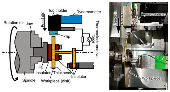
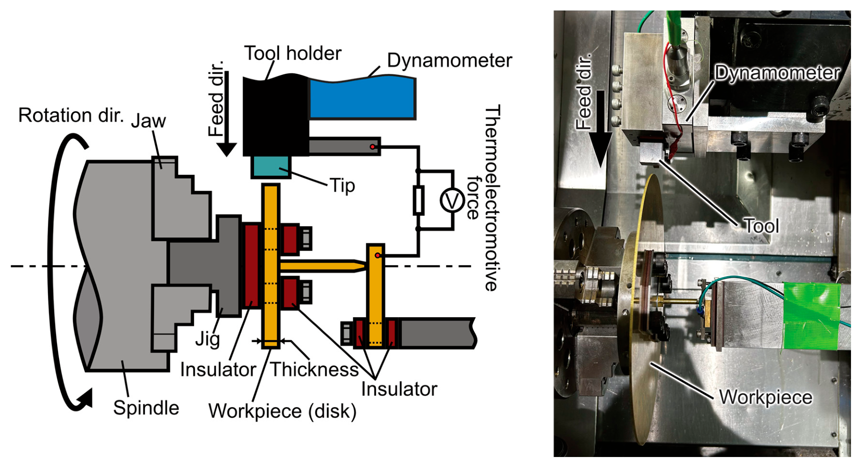
Two series of cutting experiments were conducted: one experiment aimed to validate the temperature measurement of individual faces while the other experiment sought to reveal the relation between tool wear and the measured flank-face temperature. Both experiments were conducted using the same experimental setup shown in Figure 3. Semi-orthogonal cutting was conducted by machining the outer circumference of a disk-shaped workpiece using a CNC lathe (LB-3000 EX, Okuma Corp., Oguchi, Japan). The tool was mounted on a dynamometer (9129AA, Kistler Instrumente AG, Winterthur, Switzerland), and the cutting force and thermoelectromotive force generated during cutting were measured. The cutting speed was kept constant by using a constant-cutting-speed control.
Figure 3.
Experimental schematic and overview.
The experimental conditions for validating the temperature measurements of individual faces obtained using the proposed method are summarized in Table 1. Brass, with the nominal designation of CuZn40, was used as the workpiece. Note that tool wear is unlikely to occur when machining brass. A commercially available turning insert (SNMA190612 MC5005, Mitsubishi Material Corp., Tokyo, Japan) was used as the cutting tool. Since this insert is covered with an insulating coating layer, electrical discharge machining (EDM) was applied to selectively remove the coating from either the rake face or the flank face while retaining it on the other. At the same time, the required tool geometry was formed. In this experiment, three types of tools were tested for the flank-face temperature measurement (rake-face-coated), the rake-face temperature measurement (flank-face-coated), and the dual-face temperature (non-coated). Note that before and after the cutting experiments (for brass and steel), the electrical insulation between the coated face and the tool body was confirmed by measuring the electrical resistance using a multimeter, which exceeded the upper measurement limit of 40 MΩ. The cutting speed V was varied across six steps, and the depth of cut t was varied across three steps. A relatively wide range of these conditions was chosen to allow a comprehensive investigation of their effects on the measured temperatures. Note that the width of cut was set sufficiently large enough, relative to the maximum depth of cut, so that the cutting process can be approximated as orthogonal cutting. All 18 combinations were tested once under dry conditions.
Table 1.
Experimental conditions for validating the temperature measurement of individual faces (brass).
The experimental conditions revealing the relations between tool wear and the measured flank-face temperature are summarized in Table 2. Medium carbon steel (C45, ISO) was used as the workpiece to promote the progress of flank wear. For this experiment, a commercially available coated turning insert (LNUX 32 12 48-PM 4325, AB Sandvik Coromant) was used as the cutting tool after additional machining by EDM, where the coating was also an insulating layer. In this experiment, the tool was cut out so that the coating was located only on the rake face to measure the flank-face temperature. The center height of the workpiece was offset above the rake face of the insert, such that the angle between the rake-face plane and the line from the workpiece’s center to the cutting point was maintained at 8° in order to suppress frictional chatter [21].
Table 2.
Experimental conditions for investigating the relationship between tool wear and the measured flank-face temperature (steel).
The latter experiment was conducted at a constant cutting speed of 240 m/min and a depth of cut of 0.1 mm/rev, without cutting fluid. These conditions are typically used in practice, and the width of cut was set to 3 mm so that the cutting process can also be approximated as orthogonal cutting. Each pass was controlled to a constant cutting distance of 15 m, and the tool profile and the flank-wear width were measured after every eight passes, or every 120 m of cutting distance. Passes for identifying the edge-force component (see Section 3.2.2), which is relevant to the tool wear, were included in the cumulative cutting distance, where these identifications were performed at intervals of 420 m, with the depth of cut varied across four steps.
2.4. Measurement and Data Processing
The cutting force F and thermoelectromotive force E were recorded by a digital oscilloscope (DL850E, Yokogawa Electric Corp., Musashino, Japan) at a sampling frequency of 10 kHz after low-pass filtering, with a cutoff frequency of 4 kHz. The thermoelectromotive force was measured between the tool and the workpiece—see Figure 3.
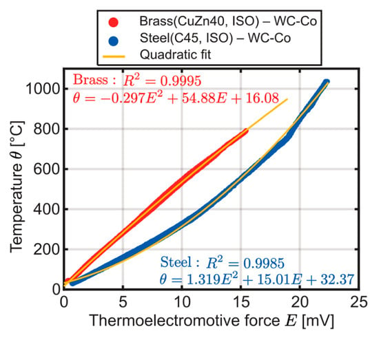
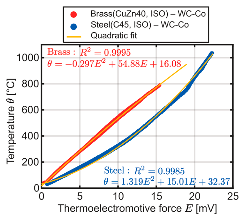
Calibration was required to obtain the temperature from the thermoelectromotive force. Calibration was conducted by heating the tool–workpiece contact in an electric furnace (ARF-16KC, Asahi Rika Seisakusho Co., Ltd., Tokyo, Japan) at a constant heating rate of 20 K/min. The reference temperature was measured using a sheathed type-K thermocouple (T35-300B2K9K05/500EXD, Okazaki Mfg. Co., Ltd., Okazaki, Japan), while the reference junction was maintained in an ice bath at 0 °C. Figure 4 shows the relationships between the thermoelectromotive force and the temperature for each tool and workpiece combination. For each combination, the data were fitted with a quadratic function, and the fitted functions, with the parameters averaged over the repeated calibrations, were used for conversion, where the calibration is repeated twice for the brass combination and three times for the steel combination. The maximum standard deviations between the repeated calibration runs were 7.1 °C for brass and 6.8 °C for steel, while the root-mean-square deviations of the calibration data from the fitted curves were 5.2 °C and 14.2 °C, respectively. During the cutting experiments, the laboratory air-conditioning system was set to 24 °C, and this temperature was assumed to be the room temperature, i.e., the reference-junction temperature. The TEMF was converted into a temperature using the calibration curve referenced to 0 °C, and the room temperature was added as an offset. Note that temperatures above 800 °C for the brass combination were obtained by extrapolating the calibration equation. The maximum extrapolation was approximately 150 °C beyond the calibration range. Although the calibration equation showed good agreement with the experimental data within the calibration range, its validity at higher temperatures was not experimentally verified. Therefore, the extrapolated temperatures should be regarded as estimates with greater uncertainty than those within the calibration range.
Figure 4.
Relationships between the thermoelectromotive force E and temperature θ for each tool and workpiece combination.
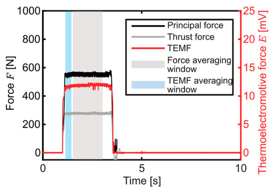
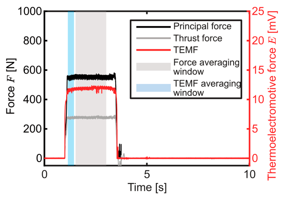
Figure 5 shows an example of the recorded waveforms of the cutting force and thermoelectromotive force during the cutting of brass. The cutting force was averaged in the middle of the cutting (gray area), and the thermoelectromotive force was averaged immediately after its rise (light-blue area). Regarding the latter averaging, during cutting, thermoelectromotive forces generated at points other than the tool–workpiece interface may be superimposed on the measured signal. Therefore, the TEMF was averaged over a 0.3 s interval starting one rotational period after the initial rise to minimize such contributions. The same criterion was applied under all cutting conditions and wear stages to ensure a consistent temperature evaluation. The averaged thermoelectromotive force was converted into a temperature using the calibration function shown in Figure 4. Although each cutting condition was tested once, the TEMF was continuously recorded at a sampling frequency of 10 kHz. The temperature was calculated from the average TEMF over the specified averaging period, e.g., 0.3 s, which contained 3001 data points. The mean and the standard deviation of the TEMF within this period were also evaluated to quantify the temporal variability of the measured signal. For example, the TEMF at the cutting speed of 300 m/min and the depth of cut of 0.2 mm was 14.316 ± 0.204 mV (mean ± standard deviation), demonstrating the temporal stability of the measurement signal.
Figure 5.
Example of measured waveform with the rake-face-coated tool at a cutting speed V of 300 m/min and depth of cut t of 0.2 mm.
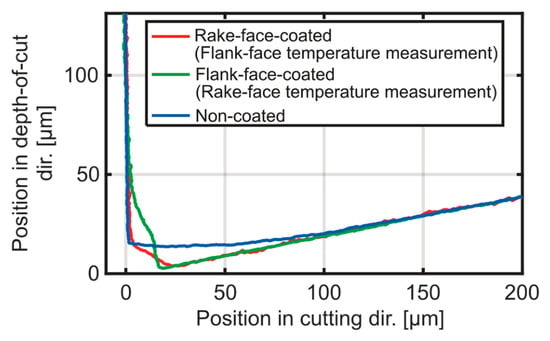
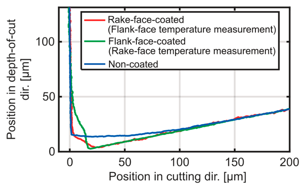
The tool profile was measured with a laser microscope (VK-X1100, Keyence Corp., Osaka, Japan) using a 50× objective lens. Five measurement lines perpendicular to the cutting edge were set, and the profiles along these lines were averaged. After the measurement, the profiles were aligned by applying a coordinate rotation so that the rake face of each profile coincided with the vertical axis for validation experiment. Figure 6 shows the profiles of the tools in the initial state. Note that the tool geometries could not be reproduced exactly because the EDM of the insulating layer was technically difficult. Although some differences in geometry remained and may have affected the cutting force and temperature, their influence on the experimental results is expected to be relatively small, particularly at larger depths of cut.
Figure 6.
Tool profiles at their initial states before validation experiments.
The edge-force component, which is the force that occurs when the flank face plows the finished surface of the workpiece and generally does not depend on the depth of cut, was identified from the cutting forces measured at different depths of cut (three depths in the former experiment and four depths in the latter experiment). According to the established cutting-force model [22], the cutting force is expressed as the sum of the material-removing-force component proportional to the uncut chip thickness (depth of cut) and the edge-force component independent of the uncut chip thickness when the width of cut is constant. Hence, the edge-force component is obtained as the cutting force extrapolated to the depth of cut of zero using linear regression.
3. Validation of Independent Temperature Measurements and Flank-Face Temperatures During Flank-Wear Progression
3.1. Validation of Temperature Measurements of Individual Faces (Brass)
3.1.1. Effect of an Insulating Layer on the Friction Angle
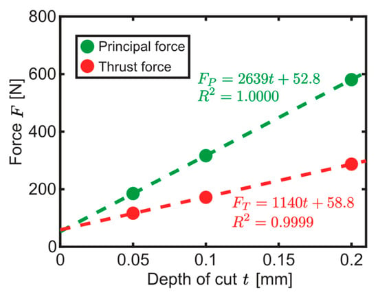
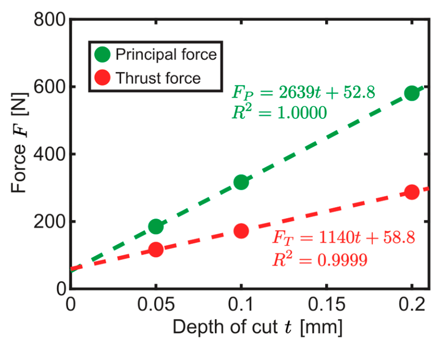
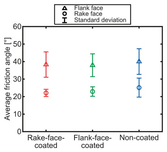
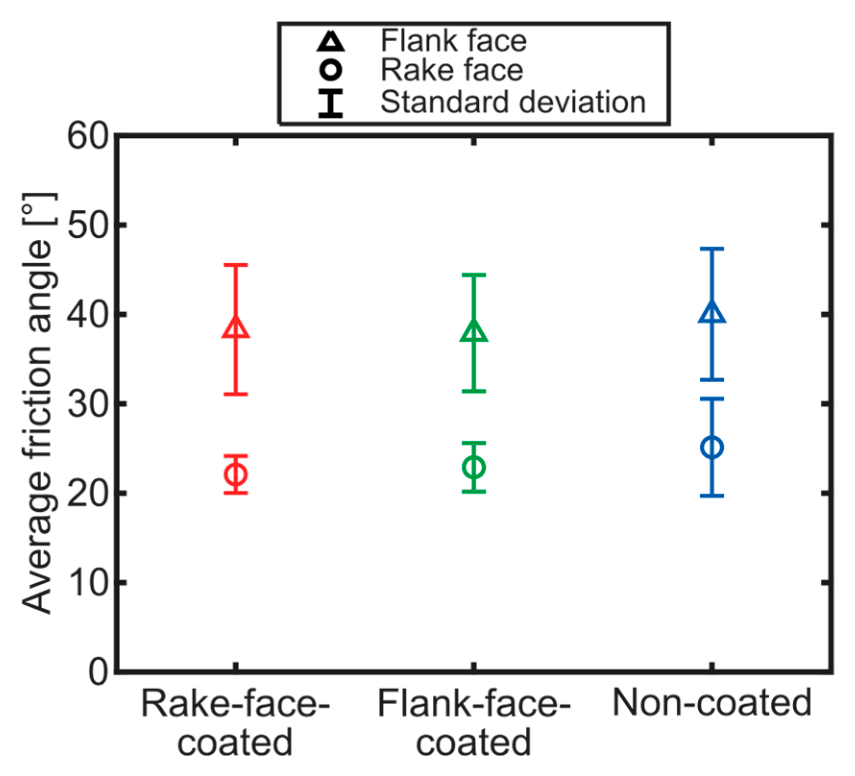
The proposed method assumes that the insulating layer does not affect the frictional behavior at the tool–workpiece interface and thus, the heat generation. To confirm this assumption, the friction angles were compared among the three types of tools. Figure 7 shows an example of the cutting force against the depth of cut at the cutting speed of 100 m/min with the rake-face-coated tool, from which the edge-force component was obtained by extrapolation to a depth of cut of zero. Figure 8 shows the friction angles on the rake and flank faces obtained from the measured cutting forces. The friction angle on the rake face was calculated from the cutting force after subtracting the edge-force component, whereas that on the flank face was calculated from the edge-force component itself. Specifically, the rake-face friction angle is determined from the ratio of the cut-depth-direction component to the cutting-direction component of the cutting force after subtraction (because the rake angle is zero here), while the flank-face friction angle is determined from the ratio of the cutting-direction component to the cut-depth-direction component of the edge force. No clear difference in the friction angle was observed between the tools, suggesting that the frictional conditions did not differ substantially. However, similar friction angles do not necessarily indicate identical frictional heat generation or heat partitioning into the tool. Although the insulating coating was relatively thin, e.g., 4 or 7 μm for the inserts utilized in this paper, and its thermal influence is expected to be limited [23], the coating may affect heat partitioning at the tool–workpiece interface [24]. Nevertheless, because the coating thickness was only several micrometers and the observed temperature trends were consistent with the expected heat-transfer behavior, the measured differences were considered to mainly reflect the differences between the rake-face and flank-face measurement regions. Note that neither breakage nor delamination of the insulating layer was observed after all the experiments.
Figure 7.
Example of the measured cutting force and identification of edge-force component (brass).
Figure 8.
Friction angles on rake and flank faces (brass). Circles represent mean values of friction angle on the rake face, and triangles represent those on the flank face. Error bars represent standard deviations calculated from the results obtained at different cutting speeds rather than repeated measurements under identical cutting conditions.
3.1.2. Comparison of Rake-Face, Flank-Face, and Dual-Face Temperatures
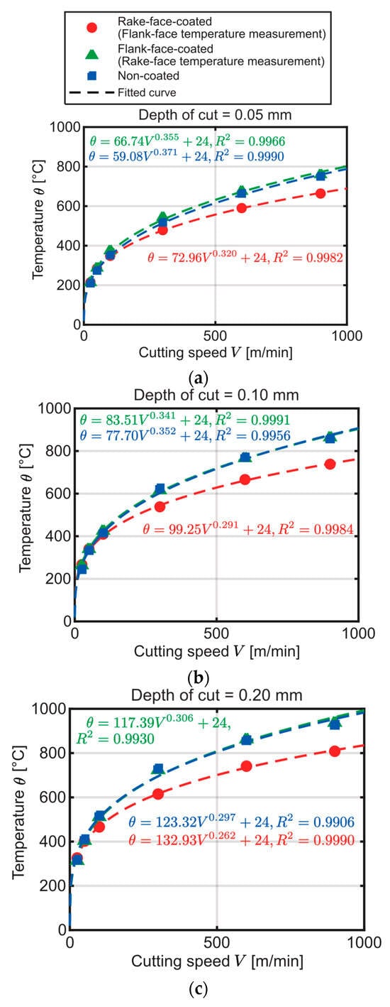
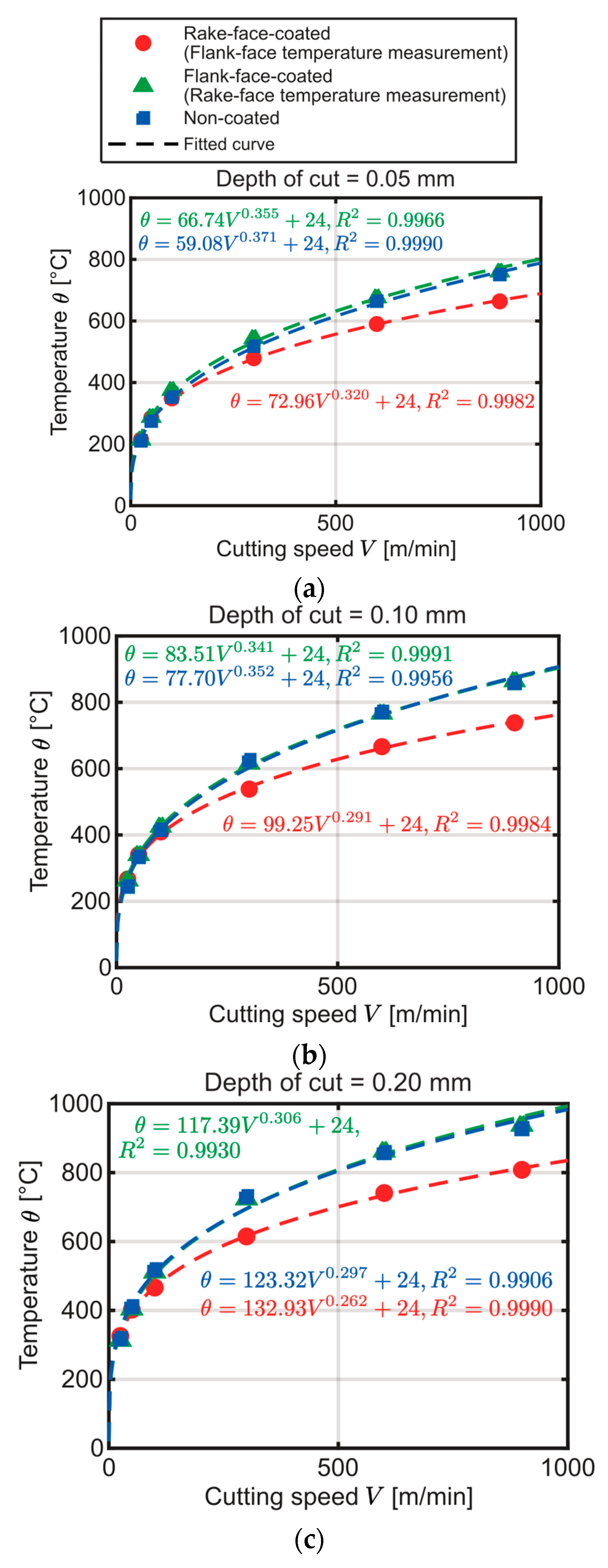
To verify that the proposed method measures the rake-face and flank-face temperatures independently, the measured rake-face, flank-face, and dual-face temperatures are compared. Figure 9 shows these temperatures as a function of the cutting speed for each depth of cut. The dashed curves in the figure are power functions of the cutting speed fitted to the measured temperatures by the least-squares method. All the temperatures increase with the cutting speed and depth of cut. When comparing the temperatures on the flank face and the rake face at low cutting speeds (≤50 m/min), the differences among the temperatures are small. At higher cutting speeds, the rake-face temperature becomes higher than the flank-face temperature, and the difference between them increases with the cutting speed. One possible reason is that, as the cutting speed increases, the heat advection by the material flow of the chip increases the fraction of heat generated in the shear plane that flows to the chip side (rake face). A similar tendency is also observed with the increasing depth of cut, which can likewise be explained by the same mechanism.
Figure 9.
Rake-face, flank-face, and dual-face temperatures as function of cutting speed V for depths of cut t of (a) 0.05 mm, (b) 0.10 mm, and (c) 0.20 mm (brass).
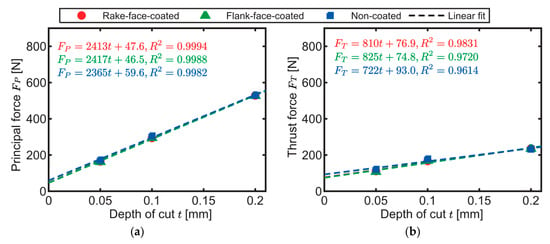
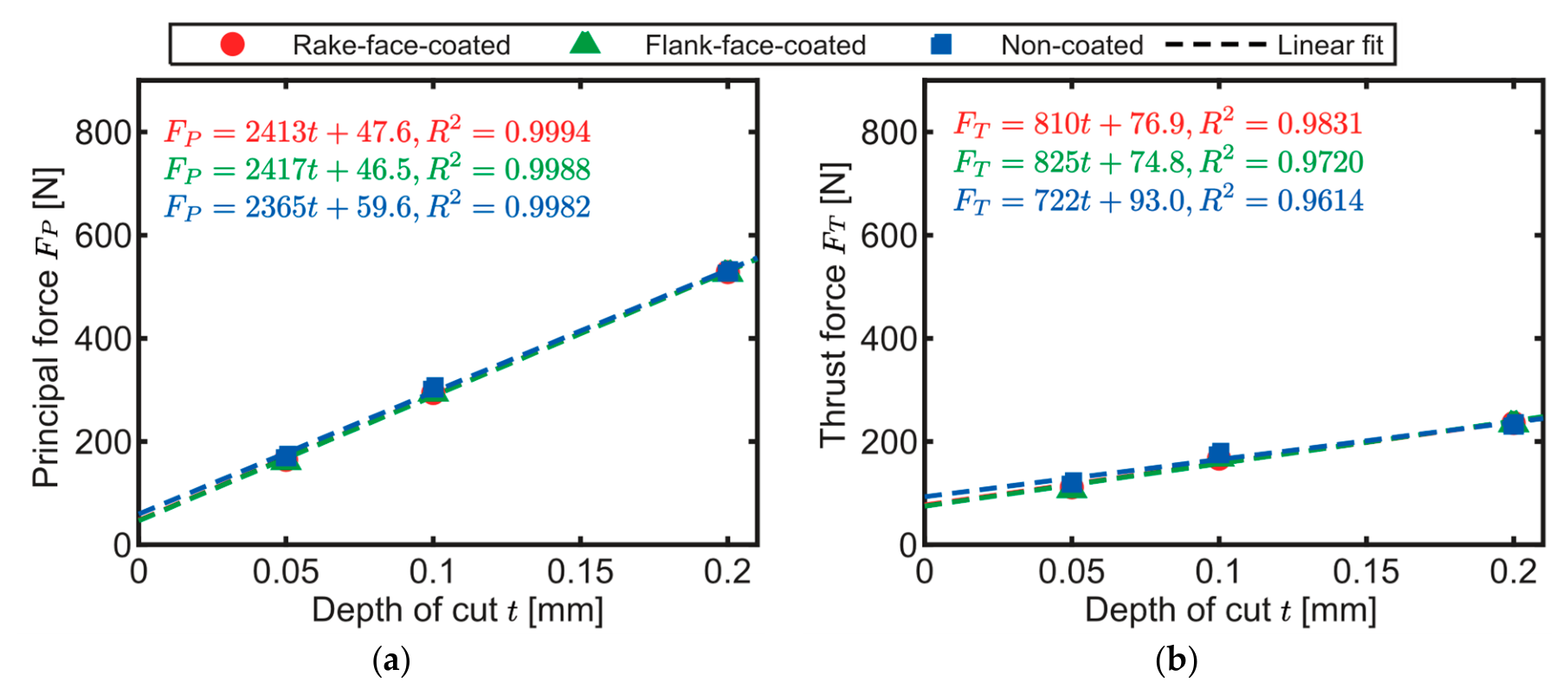
At small depths of cut, the rake-face temperature is slightly higher than the dual-face temperature, whereas the two temperatures are almost identical at larger depths of cut. This is because the proportion of the contact area on the rake face, relative to the total contact area, increases with the increasing depth of cut. Consequently, the dual-face temperature approaches the rake-face temperature. Note that at higher cutting speeds, the cutting forces were nearly identical among the three types of tools under the same cutting conditions, whereas clear differences were observed in the measured temperatures. For reference, the measured principal and thrust forces at the cutting speed of 900 m/min are shown in Figure 10. It can also be observed that the forces are nearly identical even at a small depth of cut. Therefore, the differences in the initial tool geometry were not considered to be the primary cause of the observed temperature differences, although their influence cannot be completely excluded.
Figure 10.
Measured (a) principal forces and (b) thrust forces at a cutting speed V of 900 m/min against increasing depths of cut t (brass).
These results indicate that the proposed method can measure the flank-face and rake-face temperatures independently, since the measured temperatures show trends consistent with the heat transfer behavior expected from the cutting conditions. Note that even when the extrapolated temperatures are excluded, the remaining measured temperatures still exhibit trends consistent with the expected behavior.
3.2. Effect of Flank Wear on the Flank-Face Temperature (Steel)
3.2.1. Progress of Flank Wear with the Cutting Distance
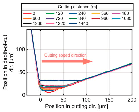
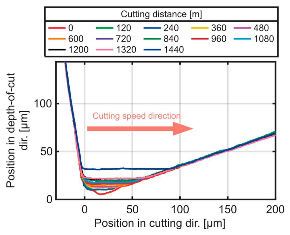
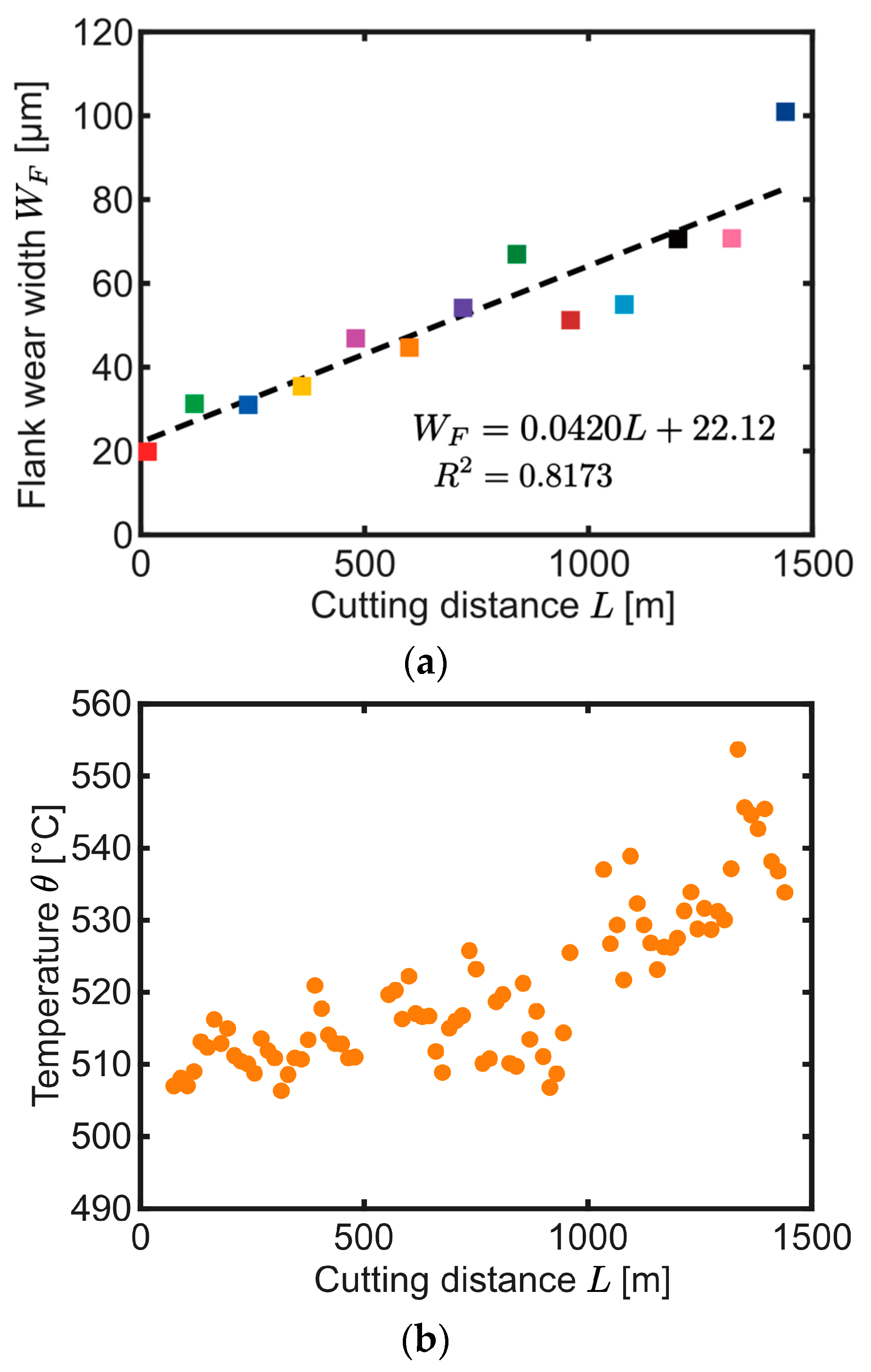
To confirm the progress of flank wear, the tool profiles were measured at each cutting distance. Figure 11 shows the tool profile at each cutting distance. The profiles were rotated by 8° so that the cutting direction is horizontal in the figure. The flank wear progresses with the cutting distance, and the flank-wear width increases from approximately 20 μm to 100 μm. Because the insulating layer was located on the rake face in the tool-wear experiment, the temperature measured by the proposed method corresponds to the flank-face temperature. Thus, the flank-face temperature can be monitored directly as flank wear progresses.
Figure 11.
Measured tool profiles at each cutting distance (steel).
3.2.2. Changes in the Flank-Face Temperature and Cutting Force with Flank-Wear Progression
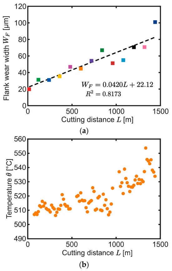
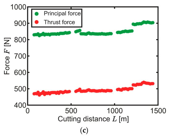
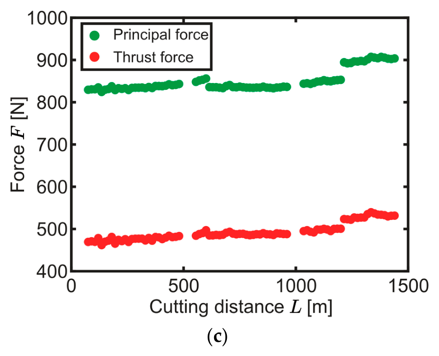
Figure 12 shows the flank-wear width, flank-face temperature, and cutting force against the cutting distance. The flank-wear width increases almost linearly with the cutting distance (Figure 12a), and the flank-face temperature and cutting force also increase (Figure 12b,c). Regarding temperature, the temperature measured by the conventional tool–workpiece thermocouple method in the literature behaved differently with the progression of flank wear. In the face milling of carbon steel, the thermoelectromotive force at the start of cut, which corresponds to the temperature, did not change monotonically with the flank-wear width; the temperature of the worn tool was lower than that of the new tool at the wear widths of 0.2–0.4 mm and was recovered at 0.6 mm [25]. One possible explanation for this behavior is that the contact area in the conventional method includes both the rake and flank faces, and the proportion of the contact area on the flank face relative to the total contact area increases as the flank wear progresses. More specifically, when the wear width is small, the temperature of the flank face should be smaller than that of the rake face; the dual-face temperature should decrease as wear progresses. As wear progresses even further, the flank-face temperature should increase and eventually become larger than that of the rake face; the dual-face temperature should increase eventually. However, this interpretation remains hypothetical because the present experiments did not examine whether the flank-face temperature would eventually exceed the rake-face temperature during wear progression, which remains a future investigation. In contrast, the proposed method measured only the flank-face temperature, which increased gradually with the flank-wear width; the temperature relevant to the flank wear can be measured directly. Note that no apparent breakage or delamination of the insulating layer was observed after the steel-cutting experiment. Furthermore, the measured flank-face temperature did not exhibit any abrupt discontinuity that would suggest a sudden loss of electrical insulation. These observations support the effectiveness of the insulating layer throughout the cutting experiment.
Figure 12.
(a) Progression of flank-wear width WF, (b) flank-face temperature θ, and (c) cutting force F against an increasing cutting distance (steel).
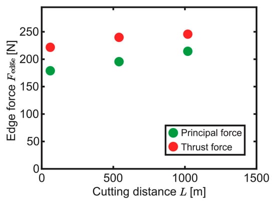
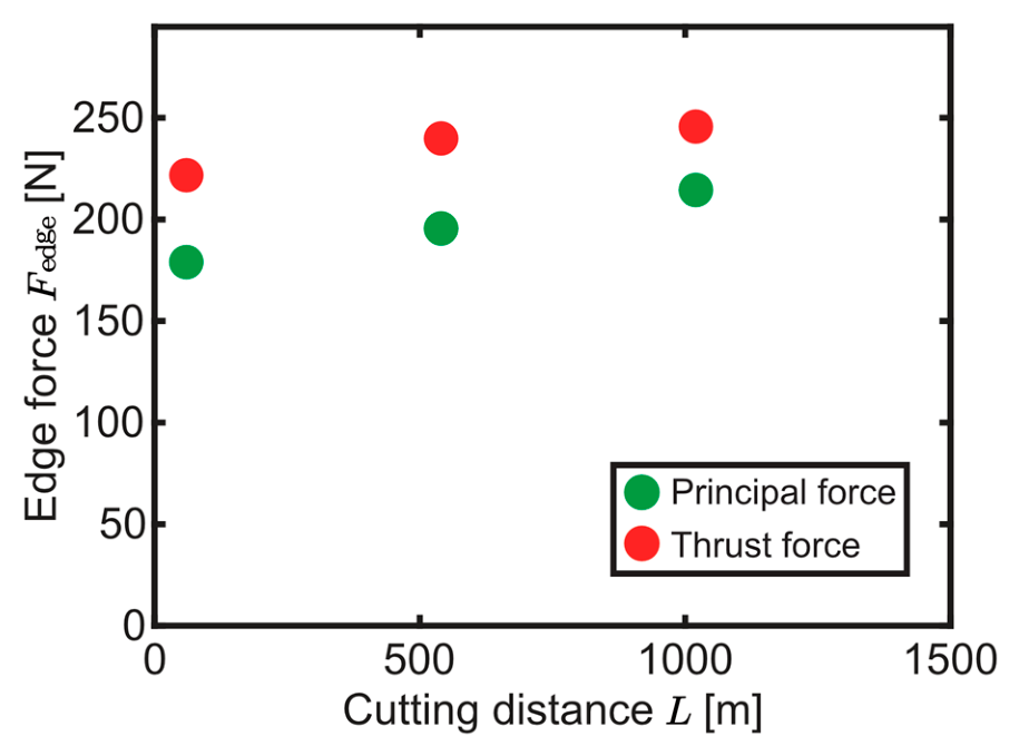
To examine how the contact conditions of the flank face changed with flank wear, the edge-force component was identified from the measured cutting forces. Figure 13 shows the edge-force component against the cutting distance. It increases with the cutting distance as flank wear progresses. Because the edge-force component is the force acting mainly on the flank face, its increase suggests an increase in the contact area between the flank face and the finished surface of the workpiece, resulting in greater frictional heat generation. This interpretation is consistent with the increase in the flank-face temperature.
Figure 13.
Relationship between edge forces Fedge and the cutting distance L (steel).
It should be noted that flank wear progresses steadily in the present tool-wear experiment and may not have reached the accelerated wear region, in which flank wear progresses rapidly. The flank-face temperature in that region remains to be investigated further.
4. Conclusions
In this study, a method for directly and independently measuring the flank-face and rake-face temperatures was proposed by combining an electrically insulating layer with the tool–workpiece thermocouple method. The following conclusions were obtained.
- •
- The flank-face and rake-face temperatures can be obtained directly and independently by placing an insulating layer on the rake face and the flank face. The dual-face temperature can be obtained without the insulating layer.
- •
- In the cutting of brass, the friction angle was nearly the same between tools with and without the insulating layer, and neither breakage nor delamination of the layer was observed. The measured temperatures showed trends consistent with the heat-transfer behavior expected from the cutting conditions: the rake-face temperature became higher than the flank-face temperature at higher cutting speeds and larger depths of cut, and the dual-face temperature approached the rake-face temperature at larger depths of cut. These findings support the feasibility of the proposed method for directly and independently measuring the apparent average temperatures of the rake and flank faces.
- •
- In the cutting of medium carbon steel, the flank-face temperature increased as the flank wear progressed with the cutting distance. The edge-force component also increased, suggesting that the larger contact area between the flank face and the finished surface of the workpiece increased the frictional heat generation on the flank face. The proposed method successfully monitored the flank-face temperature change associated with flank-wear progression.
The flank wear may not have reached the accelerated wear region in the present experiment, and the flank-face temperature in that region remains to be further investigated.
Author Contributions
Conceptualization, E.S.; methodology, S.T., T.H. and E.S.; software, S.T.; validation, S.T., T.H., A.I. and E.S.; formal analysis, S.T., T.H. and E.S.; investigation, S.T., T.H., A.I. and E.S.; resources, T.H. and E.S.; data curation, S.T.; writing—original draft preparation, S.T.; writing—review and editing, S.T., T.H. and E.S.; visualization, S.T., T.H. and E.S.; supervision, T.H. and E.S.; project administration, T.H. and E.S.; funding acquisition, T.H. and E.S. All authors have read and agreed to the published version of the manuscript.
Funding
This research was partially funded by the Human resource development and research project on production technology for aerospace industry: Subsidy from Gifu Prefecture.
Data Availability Statement
The original contributions presented in this study are included in the article. Further inquiries can be directed to the corresponding author.
Acknowledgments
The authors would like to express their sincere thanks to Mitsuya Ohhira, an engineer of Amada Machinery Co., Ltd., for his support in conducting the preliminary experiments. In addition, the authors would like to thank the engineers of Murata Machinery, Ltd.; Fujiseiko, Ltd.; and Amada Machinery Co., Ltd. for their help in conducting the present research.
Conflicts of Interest
The authors declare no conflicts of interest.
References
- Wang, J.Y.; Liu, C.R.; Wang, K.K. The Effect of Tool Flank Wear on the Heat Transfer, Thermal Damage and Cutting Mechanics in Finish Hard Turning. CIRP Ann. 1999, 48, 53–58. [Google Scholar] [CrossRef] [Scilit]
- Loewen, E.G.; Shaw, M.C. On the Analysis of Cutting-Tool Temperatures. Trans. Am. Soc. Mech. Eng. 1954, 76, 217–225. [Google Scholar] [CrossRef] [Scilit]
- Komanduri, R.; Hou, Z.B. Thermal modeling of the metal cutting process: Part I—Temperature rise distribution due to shear plane heat source. Int. J. Mech. Sci. 2000, 42, 1715–1752. [Google Scholar] [CrossRef] [Scilit]
- Komanduri, R.; Hou, Z.B. Thermal modeling of the metal cutting process—Part II: Temperature rise distribution due to frictional heat source at the tool–chip interface. Int. J. Mech. Sci. 2001, 43, 57–88. [Google Scholar] [CrossRef] [Scilit]
- Komanduri, R.; Hou, Z.B. Thermal modeling of the metal cutting process—Part III: Temperature rise distribution due to the combined effects of shear plane heat source and the tool–chip interface frictional heat source. Int. J. Mech. Sci. 2001, 43, 89–107. [Google Scholar] [CrossRef] [Scilit]
- Jiang, Q.; Song, J. A Review on Cutting Force and Thermal Modeling, Toolpath Planning, and Vibration Suppression for Advanced Manufacturing. Machines 2026, 14, 60. [Google Scholar] [CrossRef] [Scilit]
- Bazaz, S.M.; Ratava, J.; Lohtander, M.; Varis, J. An Investigation of Factors Influencing Tool Life in the Metal Cutting Turning Process by Dimensional Analysis. Machines 2023, 11, 393. [Google Scholar] [CrossRef] [Scilit]
- Herbert, E.G. The Measurement of Cutting Temperatures. Proc. Inst. Mech. Eng. 1926, 110, 289–329. [Google Scholar] [CrossRef] [Scilit]
- Davies, M.A.; Ueda, T.; M’Saoubi, R.; Mullany, B.; Cooke, A.L. On The Measurement of Temperature in Material Removal Processes. CIRP Ann. 2007, 56, 581–604. [Google Scholar] [CrossRef] [Scilit]
- Boothroyd, G. Photographic technique for the determination of metal cutting temperatures. Br. J. Appl. Phys. 1961, 12, 238–242. [Google Scholar] [CrossRef] [Scilit]
- Biermann, D.; Kirschner, M.; Pantke, K.; Tillmann, W.; Herper, J. New coating systems for temperature monitoring in turning processes. Surf. Coat. Technol. 2013, 215, 376–380. [Google Scholar] [CrossRef] [Scilit]
- Tillmann, W.; Vogli, E.; Herper, J.; Biermann, D.; Pantke, K. Development of temperature sensor thin films to monitor turning processes. J. Mater. Process. Technol. 2010, 210, 819–823. [Google Scholar] [CrossRef] [Scilit]
- Guimarães, B.; Rosas, J.; Fernandes, C.M.; Figueiredo, D.; Lopes, H.; Paiva, O.C.; Silva, F.S.; Miranda, G. Real-Time Cutting Temperature Measurement in Turning of AISI 1045 Steel through an Embedded Thermocouple—A Comparative Study with Infrared Thermography. J. Manuf. Mater. Process. 2023, 7, 50. [Google Scholar] [CrossRef] [Scilit]
- Xia, Q.; Gillespie, D.R.H. Quasi-static finite element modelling of thermal distribution and heat partitioning for the multi-component system of high speed metal cutting. J. Mater. Process. Technol. 2020, 275, 116389. [Google Scholar] [CrossRef] [Scilit]
- Young, H.-T. Cutting temperature responses to flank wear. Wear 1996, 201, 117–120. [Google Scholar] [CrossRef] [Scilit]
- Kryzhanivskyy, V.; M’Saoubi, R.; Nordgren, A.; Bushlya, V. Experimental study and modeling of the heat flux acting on the tool flank when machining. Procedia CIRP 2021, 102, 97–102. [Google Scholar] [CrossRef] [Scilit]
- Ueda, T.; Suzuki, K.; Shamoto, E. Fundamental Study on Cutting Temperature in High Speed Cutting of Difficult-to-Cut Materials. In Proceedings of the Machining Innovations Conference (MIC), Garbsen, Germany, 2 December 2020. [Google Scholar] [CrossRef] [Scilit]
- Usui, E.; Shirakashi, T.; Kitagawa, T. Analytical prediction of cutting tool wear. Wear 1984, 100, 129–151. [Google Scholar] [CrossRef] [Scilit]
- Hirao, M. Determining temperature distribution on flank face of cutting tool. J. Mater. Shap. Technol. 1989, 6, 143–148. [Google Scholar] [CrossRef] [Scilit]
- Volke, P.; Saelzer, J.; Zabel, A.; Biermann, D. Influence of cutting tool coating on rake and flank face temperatures by operando pyrometric temperature measurement during orthogonal turning of AISI 316L. Wear 2025, 571, 205848. [Google Scholar] [CrossRef] [Scilit]
- Hayasaka, T.; Jung, H.; Azuma, K.; Shamoto, E. Consolidated chatter stability prediction model considering material removing and ploughing processes. Precis. Eng. 2019, 59, 120–133. [Google Scholar] [CrossRef] [Scilit]
- Altintas, Y. Manufacturing Automation: Metal Cutting Mechanics, Machine Tool Vibrations, and CNC Design, 2nd ed.; Cambridge University Press: Cambridge, UK, 2012. [Google Scholar] [CrossRef] [Scilit]
- Du, J.; Zhang, J.; Wang, L. Heat partition and rake face temperature in the machining of H13 steel with coated cutting tools. Int. J. Adv. Manuf. Technol. 2018, 94, 3691–3702. [Google Scholar] [CrossRef] [Scilit]
- Rech, J.; Battaglia, J.L.; Moisan, A. Thermal influence of cutting tool coatings. J. Mater. Process. Technol. 2005, 159, 119–124. [Google Scholar] [CrossRef] [Scilit]
- Murata, M.; Kurokawa, S.; Ohnishi, O.; Uneda, M.; Doi, T. Real-Time Evaluation of Tool Flank Wear by In-Process Contact Resistance Measurement in Face Milling. J. Adv. Mech. Des. Syst. Manuf. 2012, 6, 958–970. [Google Scholar] [CrossRef] [Scilit]

Disclaimer/Publisher’s Note: The statements, opinions and data contained in all publications are solely those of the individual author(s) and contributor(s) and not of MDPI and/or the editor(s). MDPI and/or the editor(s) disclaim responsibility for any injury to people or property resulting from any ideas, methods, instructions or products referred to in the content. |
© 2026 by the authors. Licensee MDPI, Basel, Switzerland. This article is an open access article distributed under the terms and conditions of the Creative Commons Attribution (CC BY) license.