


Highlights
What are the main findings?
- Hybrid anti-icing architectures combining electrothermal heating, icephobic coatings, and intelligent control systems provide the most energy-efficient strategy for UAV propeller protection under known icing conditions.
- Low-Reynolds-number icing significantly amplifies aerodynamic degradation in UAV propellers, where ice layers below 1 mm can reduce lift performance by up to 40% and induce critical rotor imbalance.
What are the implications of the main findings?
- Adaptive electrothermal systems operating in pulsed mode can reduce anti-icing energy consumption by more than 40% compared with conventional continuous-heating approaches, improving UAV endurance in cold-weather missions.
- The integration of multifunctional materials such as superhydrophobic coatings, CNT-based conductive composites, and piezoelectric actuators establishes a viable pathway toward certifiable lightweight ice-protection systems for next-generation autonomous UAV platforms.
Abstract
Atmospheric icing is one of the most critical meteorological hazards for unmanned aerial vehicles (UAV), whose operation under adverse conditions—high latitudes, elevated altitudes, long-endurance missions without pilot intervention—particularly exposes them to ice accumulation on aerodynamic surfaces and propellers. Unlike manned aviation, where this phenomenon has been extensively studied and regulated, a significant knowledge gap exists in the UAV domain that limits the development of effective protection systems adapted to energy constraints. This article provides an integrative review—conducted with a systematic search strategy following PRISMA reporting guidelines—of atmospheric ice formation mechanisms, their specific effects on UAV propellers, and the two most promising mitigation approaches: electrothermal modelling for the optimisation of electric heating systems and the development of functional surface materials including superhydrophobic coatings (SHC); composites with conductive nanofillers (graphene, carbon nanotubes); and piezoelectric actuators. The analysis demonstrates that hybrid systems combining passive and active strategies managed by intelligent control represent the most viable solution for extending UAV operational envelopes under known icing conditions, with a projected reduction in anti-icing system energy consumption of at least 40% relative to conventional continuous heating. This estimate is based on the most conservative published evidence: pulsed electrothermal de-icing achieves 40–60% savings versus continuous anti-icingSHC-assisted hybrid heating reduces IPS power by more than 80% on static aerofoils; and rotary-wing pulsed systems reduce mean consumption by 60–75% relative to continuous operation. Key research gaps are identified, and a prioritised future research agenda is proposed to support the development of certifiable anti-icing systems for rotary-wing UAV platforms.
1. Introduction
Airframe icing constitutes one of the most severe meteorological hazards in aviation, encompassing a complex coupling between atmospheric microphysics, surface thermodynamics, and aerodynamic performance degradation. When an aircraft traverses a cloud containing supercooled large droplets (SLD) or encounters freezing precipitation, impinging water droplets freeze upon contact with exposed surfaces, forming accretion structures whose geometry—rime, glaze, or mixed ice—depends critically on the liquid water content (LWC), median volumetric diameter (MVD), freestream temperature (), and collection efficiency of the surface [1,2]. The thermodynamic foundation of this process was formalised by Messinger [1], whose steady-state energy balance at the impingement surface remains the canonical framework for icing accretion modelling. Subsequent refinements by Ruff and Berkowitz [3], the LEWICE [4] and FENSAP-ICE [5] computational codes have extended this formulation to three-dimensional unsteady multi-step accretion scenarios.
The aerodynamic consequences of ice accretion are well documented for transport-category aircraft. Progressive accumulation on lifting surfaces disrupts the pressure distribution over the airfoil, induces early boundary-layer separation, and degrades both maximum lift coefficient () and stall margin. The Federal Aviation Administration (FAA) Advisory Circular AC 91-74B establishes that intercycle and residual ice formations can reduce by up to 30% and increase profile drag by more than 40%, depending on ice shape, surface roughness, and chord Reynolds number [6]. Lynch and Khodadoust [7] conducted an exhaustive meta-analysis of icing wind tunnel experiments and confirmed reductions of up to 50% in and drag increments of 100–200% for glaze ice horn geometries on NACA 0012 and 23012 sections, effects directly attributable to the formation of large separation bubbles downstream of the ice horn. The severity of performance penalties is further modulated by ice surface roughness: Bragg et al. [8] demonstrated that even sub-millimetre roughness elements on the leading edge produce a disproportionate loss of lift curve slope through premature transition and thickening of the turbulent boundary layer, an effect particularly acute at chord Reynolds numbers below .
In the context of unmanned aerial vehicles (UAVs), the icing threat acquires a distinctly critical operational dimension. UAV platforms are expressly designed to operate under conditions that civil aviation systematically avoids: extended-endurance missions over mountainous terrain at night, sustained operations in arctic and sub-arctic theatres, loitering at altitudes presenting elevated concentrations of supercooled water (), and tactical scenarios where mission abort is operationally impermissible [9,10]. Unlike crewed aircraft, UAVs are equipped with no on-board pilot capable of perceiving anomalous vibration signatures, changes in control response, or progressive increases in power demand; ice-induced degradation therefore has the potential to proceed to structural failure or loss of control without any corrective intervention [9]. The accident record compiled by Hann et al. [11] for small and medium UAVs operating in Scandinavian conditions confirms that icing events are systematically underreported and that available meteorological forecasting tools—designed for transport aircraft with substantially different collection efficiencies—underestimate the icing exposure of small platforms by a significant margin.
The problem is compounded by aerodynamic and structural characteristics intrinsic to small and medium-class UAVs. Their propulsion systems operate at chord Reynolds numbers in the range –, a regime in which laminar separation bubbles are inherently present on uncontaminated surfaces and in which the boundary layer is highly susceptible to the additional disturbances introduced by even sub-millimetre ice roughness [8,12]. Thin aerofoil sections with leading-edge radii to the order of 0.5–2 mm present geometric collection efficiencies substantially higher than those of large-chord surfaces, accelerating accretion rates per unit of atmospheric exposure [13]. An ice layer of only 0.5–1 mm on the leading edge of a propeller blade can reduce the local lift coefficient by 30–40% and simultaneously increase rotational drag torque, degrading thrust output and propulsive efficiency in a manner entirely disproportionate to that observed on transport-aircraft wings under equivalent atmospheric conditions [8,14]. For multi-rotor platforms, this efficiency loss translates directly into reduced hover endurance and, at critical accumulation levels, into rotor asymmetry that exceeds the authority of the flight-control system [15,16].
Recent experimental and computational investigations have substantially advanced the characterisation of propeller icing on small UAVs. Hann et al. [14] performed systematic icing wind tunnel tests on a fixed-pitch propeller representative of medium-class UAVs, reporting thrust reductions of up to 35% and torque increases of 28% under glaze-ice conditions with and . Villeneuve et al. [15] extended these findings to multi-rotor configurations, demonstrating that non-uniform accretion between coaxial rotors induces vibrational imbalances detectable in ESC current signatures, a result with direct implications for sensorless on-board detection. Cao et al. [17] investigated the influence of supercooled large droplets on the aerodynamic performance of UAV aerofoils at low Reynolds numbers, establishing that SLD conditions—defined under FAR Part 25 Appendix O—produce runback ice formations at chord positions beyond 30% that are not captured by classical Appendix C certification envelopes and that are therefore particularly hazardous for platforms operating in maritime or mountain-wave environments. Computational investigations using FENSAP-ICE [18] and LEWICE [4] have confirmed the qualitative trends observed experimentally while revealing that numerical predictions diverge appreciably from measurements at the lowest Reynolds numbers (), where turbulence model limitations and transitional flow effects introduce non-negligible uncertainty [19].
The development of ice protection systems (IPS) for UAV propellers must reconcile performance requirements with stringent energy constraints, given that propulsion and avionics already consume the largest fraction of onboard battery capacity. Electrothermal systems—the dominant technology in crewed aviation [18]—have been adapted for UAV rotors in pulsed-heating configurations that reduce mean power consumption by 60–75% relative to continuous heating by exploiting ice interface temperature transients in rotary-wing configurations [15,20] (baseline: continuous anti-icing at equivalent icing severity; platform: helicopter rotor and wind turbine blade).
Passive mitigation through superhydrophobic coatings (SHC) fabricated by nanostructured sol gel, electrospun polymer, or laser ablation processes can reduce ice adhesion strength below 25 kPa and shift the dynamic contact angle above 150°, lowering the energy required for ice shedding under centrifugal loading [21,22]. Piezoelectric actuators—particularly polyvinylidene fluoride (PVDF) films and macro-fibre composites (MFC)—offer a third modality: resonant mechanical excitation of blade structures at frequencies of 100–500 Hz generates shear stresses at the ice interface that exceed adhesion strength with energy expenditures 10–50 times lower than equivalent electrothermal approaches [12,23]. The integration of these three strategies into a hierarchical hybrid architecture, governed by an adaptive controller informed by real-time ice-severity estimates from machine learning classifiers trained on vibration and thermal signatures, represents the current frontier of the field [24,25].
Despite the operational and scientific relevance of the problem, peer-reviewed literature specifically addressing ice protection for UAV propellers remains sparse relative to the body of knowledge accumulated for fixed-wing transport aircraft and, more recently, wind turbines. The majority of existing studies either extrapolate results from large-chord, high-Reynolds-number configurations whose aerodynamic regimes and thermodynamic boundary conditions differ substantially from those of small UAV propellers, or focus on detection and characterisation without extending to integrated protection solutions [26]. This knowledge gap, combined with the increasing operational deployment of UAVs in high-latitude and high-altitude theatres where icing encounters are frequent, motivates the present review.
This article examines in an integrated manner: (i) the physical mechanisms governing ice nucleation, droplet impingement, and accretion on UAV propeller blades within low-Reynolds-number aerodynamic regimes; (ii) electrothermal modelling frameworks for the design and energy optimisation of resistive heating elements, including pulsed and zone-controlled architectures; (iii) functional surface materials—superhydrophobic, icephobic, and electro-responsive coatings—as passive and active mitigation strategies; and (iv) the systems-level integration of sensing, actuation, and control layers into hybrid anti-icing architectures compatible with the energy budget of battery-powered UAVs.
The literature search was conducted systematically in Scopus, Web of Science, and Google Scholar using the following Boolean descriptors: UAV icing, drone propeller icing, electrothermal anti-icing rotary wing, superhydrophobic icephobic coating propeller, piezoelectric de-icing UAV, low Reynolds icing aerodynamics, SLD icing small aircraft, and UAV ice protection system. The temporal scope encompassed publications from 1990 to May 2025, with priority assigned to research articles indexed in Q1–Q2 journals in the aerospace engineering and materials science categories (JCR and SJR), as well as technical reports issued by NASA, FAA, EASA, and the Defence Research and Development Canada (DRDC). Grey literature was incorporated exclusively where no peer-reviewed equivalent was available for a specific data point or operational context. After a two-stage relevance and methodological quality screening—applying PRISMA guidelines [27] adapted to engineering review methodology—a corpus of 47 primary sources was retained and constitutes the bibliographic backbone of this work. The completed PRISMA 2020 checklist is available as Supplementary Material.
The article is structured as follows. Section 2 presents the systematic literature review and bibliometric characterisation of the field. Section 3 describes the atmospheric physics of ice formation and the thermodynamic framework governing accretion on rotating surfaces. Section 4 presents the experimentally and computationally validated icing effects on UAV propellers followed by the two principal mitigation technology frameworks: electrothermal modelling (Section 4.2) and functional surface materials (Section 4.3). Section 4.2 develops the electrothermal modelling framework, including analytical and finite-element formulations for pulsed heating optimisation. Section 4.3 reviews functional surface material strategies, with emphasis on icephobic coatings and piezoelectric actuation. Section 5 presents an integrative discussion of hybrid architectures, control strategies, and open research challenges. Section 6 formulates the principal conclusions and outlines priority directions for future investigation.
2. Literature Review
2.1. Regulatory Framework and Critical Research Gaps
Current aeronautical regulations (FAR Part 25 Appendix C; EASA CS-25) define icing envelopes for certified crewed aircraft based on the Appendix C continuous maximum and intermittent maximum cloud envelopes. A subsequent amendment introduced Appendix O to address Supercooled Large Droplet (SLD) conditions [28]. However, no equivalent standard exists specifically for UAVs that establishes reference icing envelopes, minimum IPS performance requirements, or certification test methodologies [29]. This regulatory void constitutes a significant obstacle to expanding UAV operational envelopes under known icing conditions and has been identified as one of the most urgent priorities for standardisation bodies, air forces and research institutions [11].
The integration of the preceding review evidence identifies six specific research gaps that remain unresolved and motivate the present analysis: (1) the absence of validated electrothermal models that correctly account for laminar-to-turbulent boundary layer transition at UAV propeller Reynolds numbers; (2) the lack of systematic experimental ice accretion datasets for rotating propellers at , representative of inner-span blade sections; (3) the insufficient characterisation of icephobic coating durability under the combined action of centrifugal stress, high-velocity erosion and repeated icing–de-icing cycling; (4) the limited understanding of the coupling between droplet collection efficiency and aeroelastic blade deformation under ice-induced imbalance loads; (5) the absence of standard UAV icing certification envelopes and associated test protocols; and (6) the scarcity of studies addressing the acoustic signature modification induced by propeller icing, which constitutes an operationally critical parameter in ISTAR-mission UAV platforms.
Table 1 summarises the most relevant contributions identified in the review, organised chronologically by thematic area.
Table 1.
Key Contributions in the Literature on UAV and UAV Propeller Icing, Surface Materials, and Electrothermal Mitigation Systems.
2.2. Systematic Search Methodology and Integrative Synthesis
This review was conducted as an integrative review with a systematic search strategy following the Preferred Reporting Items for Systematic Reviews and Meta-Analyses (PRISMA) reporting guidelines, adapted to the engineering review context. Given the heterogeneity of available evidence, a narrative synthesis was adopted rather than quantitative meta-analysis. The methodological framework ensures transparency and reproducibility in the identification and selection of relevant literature on UAV icing mitigation.
2.2.1. Search Strategy and Information Sources
A comprehensive literature search was executed across three major bibliographic databases: Scopus, Web of Science, and Google Scholar. The search covered publications from January 1990 to May 2025, encompassing the entire modern period of UAV development and icing research. Grey literature sources—including NASA technical reports, FAA Advisory Circulars, EASA Certification Specifications, and Defence Research and Development Canada (DRDC) technical memoranda—were incorporated exclusively where peer-reviewed equivalents were unavailable for critical operational data or certification standards.
The Boolean search strategy employed domain-specific descriptors organised in three thematic clusters:
- UAV icing phenomena: “UAV icing”, “drone propeller icing”, “unmanned aerial vehicle ice accretion”, “low Reynolds icing aerodynamics”, “SLD icing small aircraft”
- Mitigation technologies: “electrothermal anti-icing rotary wing”, “superhydrophobic icephobic coating propeller”, “piezoelectric de-icing UAV”, “UAV ice protection system”
- Functional materials: “carbon nanotube anti-icing”, “graphene electrothermal heating”, “SLIPS icephobic coating”, “PVDF piezoelectric de-icing”
Table 2 presents the complete search string syntax adapted for each database.
Table 2.
Database-specific search string syntax.
2.2.2. Eligibility Criteria
Studies were included if they met the following criteria:
Inclusion criteria:
- Published in peer-reviewed journals indexed in Q1 or Q2 quartiles (Journal Citation Reports—JCR or SCImago Journal Rank—SJR) in the categories: Aerospace Engineering, Materials Science (Multidisciplinary), Mechanical Engineering, or Meteorology & Atmospheric Sciences. This criterion was applied as the primary quality filter; however, given the small size of the UAV propeller icing literature, a supplementary informal screening of Q3/Q4 and conference sources was conducted. No quantitative datasets absent from the Q1/Q2 corpus were identified; the limitation is acknowledged in Section 2.2.5.
- Reports original experimental data, validated numerical simulations (CFD, FEM), or systematic reviews on ice accretion, aerodynamic performance degradation, or mitigation technologies applicable to UAV platforms.
- Addresses aerodynamic regimes with chord Reynolds numbers Re , representative of small-to-medium UAV propellers.
- Written in English.
- Full text accessible through institutional subscriptions or open-access repositories.
Exclusion criteria:
- Studies exclusively focused on transport-category aircraft (chord Re ) without low-Reynolds validation or applicability discussion;
- Conference abstracts, unpublished dissertations, or preprints without subsequent peer-reviewed publication (exception: NASA/FAA/EASA technical reports cited for certification standards);
- Studies on wind turbine icing without explicit aerodynamic or geometric relevance to UAV rotors;
- Theoretical models without experimental or high-fidelity numerical validation;
- Duplicate publications of the same dataset in multiple venues.
2.2.3. Study Selection Process
The study selection process was conducted in two stages by three independent reviewers (authors P.N.L., C.A.G., and R.A.), with disagreements resolved through consensus discussion. Figure 1 presents the PRISMA flow diagram documenting the identification, screening, eligibility assessment, and final inclusion phases.
Figure 1.
PRISMA flow diagram documenting the systematic review selection process. The final corpus comprises 47 peer-reviewed primary sources and 12 grey-literature technical reports.
Stage 1–Title and abstract screening: Initial database queries yielded 1847 records. After removal of 312 duplicates using Zotero reference management software (version 6.0), 1535 unique records underwent title and abstract screening. Studies manifestly outside the scope (e.g., automotive icing, refrigeration systems, purely meteorological models without aeronautical application) were excluded at this stage ().
Stage 2–Full-text eligibility assessment: The remaining 237 articles were retrieved for full-text evaluation. Exclusion at this stage () was primarily due to: insufficient Reynolds number relevance (), absence of quantitative performance data (), duplication of results across multiple publications by the same research group (), and inaccessible full text despite inter-library loan requests ().
Final corpus: A total of 47 primary sources met all eligibility criteria and constitute the evidence base synthesised in Section 2, Section 3, Section 4 and Section 5. An additional 12 grey-literature technical reports (NASA TM/CR series, FAA Advisory Circulars, EASA CS-25 Appendices) were incorporated for certification context and are distinguished in the reference list.
2.2.4. Data Extraction and Quality Assessment
Data extraction was performed using a standardised template capturing: publication metadata (authors, year, journal, impact factor), study design (experimental/numerical/review), UAV platform characteristics (propeller diameter, RPM, Reynolds number range), icing conditions tested (LWC, MVD, temperature), mitigation technology category, and quantitative performance metrics (thrust loss, power consumption, ice adhesion strength, coating durability).
Quality assessment employed a domain-specific adaptation of the CASP (Critical Appraisal Skills Programme) checklist for engineering research, evaluating: (i) clarity of research objectives; (ii) appropriateness of methodology; (iii) adequacy of sample size or simulation validation; (iv) transparency of uncertainty quantification; and (v) applicability of findings to the UAV operational context. Studies were rated as high, medium, or low quality; only high- and medium-quality studies were retained after Stage 2 screening.
2.2.5. Risk of Bias
The most significant sources of bias identified across the corpus are:
- Publication bias: Negative results (e.g., coating formulations that failed durability testing) are likely underreported in the peer-reviewed literature, inflating the apparent effectiveness of proposed solutions.
- Reynolds number extrapolation: Several studies () report icing data at Re – and extrapolate conclusions to UAV propeller regimes (Re ) without direct validation, introducing epistemic uncertainty.
- Funding source influence: Industry-sponsored coating durability studies () may present optimistic assessments; these were cross-validated against independent academic replications where available.
- Geographic and climatic bias: The majority of experimental campaigns ( of 47) were conducted in North American or Northern European icing wind tunnels, potentially underrepresenting atmospheric conditions relevant to equatorial high-altitude operations.
- Quartile restriction bias: The Q1/Q2 inclusion criterion may systematically under-represent early-stage or regionally published work. In the UAV propeller icing field, where the primary literature is small, this risk is partially mitigated by the grey-literature exception and the supplementary Q3/Q4 screening described above. No evidence of systematic exclusion of relevant quantitative data was found.
- Wind-tunnel bias: Every experimental study in the final corpus () was conducted in an icing wind tunnel (IWT) or on a laboratory rotating rig. No published in-flight icing measurement for UAV propellers was identified in the systematic search or in supplementary screening. This represents a fundamental limitation of the entire UAV propeller icing evidence base, not merely of this review: IWT conditions (controlled LWC, MVD, temperature, fixed advance ratio) do not replicate the statistical variability of atmospheric icing encounters, the interaction with flight dynamics, or the unsteady meteorological transitions characteristic of real sorties. All quantitative performance data cited in this review should therefore be interpreted as lower-bound estimates of real operational degradation.
2.2.6. Synthesis Methods
Given the heterogeneity of study designs, icing conditions, and performance metrics across the included literature, a narrative synthesis approach was adopted rather than quantitative meta-analysis. Results are organised thematically according to: (i) ice formation mechanisms and aerodynamic effects (Section 3 and Section 4); (ii) electrothermal modelling frameworks (Section 4.2); (iii) functional surface materials (Section 4.3); and (iv) integrated system architectures (Section 5). Quantitative data from comparable studies were aggregated into summary tables (Tables 3 and 4) where methodological consistency permitted direct comparison.
2.2.7. Deviations from Protocol
The original review protocol, registered internally at Fundación Universitaria Los Libertadores (project code IREASE-2024-01), specified inclusion of computational fluid dynamics (CFD) studies employing RANS turbulence models exclusively. During full-text screening, this criterion was relaxed to include Large Eddy Simulation (LES) studies () due to their superior fidelity for laminar-to-turbulent transition prediction at low Reynolds numbers, a critical gap identified during preliminary analysis. This deviation increased the evidence base for Gap 1 (Section 2.1) without compromising methodological rigour.
2.3. Classical Foundations of Aeronautical Icing Research
Systematic research on in-flight icing began in earnest during the 1940s, driven primarily by the NASA Glenn Research Center, which established the Icing Research Tunnel (IRT)—still one of the world’s leading experimental facilities—and developed the LEWICE prediction code, a Lagrangian droplet trajectory and ice accretion solver that remains the industry-standard benchmark against which newer computational methods are validated [45]. These foundational works identified the critical combinations of liquid water content (LWC), median volumetric diameter (MVD) and temperature that define the icing envelope subsequently codified in FAR Part 25 Appendix C [28].
Gent et al. [46] provided a seminal multidisciplinary review covering droplet trajectory modelling, thermodynamic phase change at the impingement surface, and ice geometry prediction. Thomas et al. [47] formalised the coupled thermal-aerodynamic energy balance for electrothermal leading-edge heating systems, introducing the concept of the anti-icing heat flux distribution that later works extended to rotary-wing platforms. Bragg et al. [8] conducted an exhaustive survey of iced-aerofoil aerodynamics, quantifying and degradation as a function of accretion geometry across a wide range of Reynolds numbers and demonstrating that even small horn-ice features at the leading edge produce disproportionate penalties at low angles of attack.
2.4. Icing on UAV Platforms: From Early Recognition to Recent Experimental Characterisation
2.4.1. Early and Foundational Work
The operational impact of icing on unmanned platforms was first systematically documented by Siquig [9], who identified thrust loss and propeller imbalance as the primary failure modes and noted the absence of autonomous ice detection as a critical aggravating factor unique to UAV operations. Cao et al. [31] provided an updated review identifying, as a central gap, the inapplicability of high-Reynolds aerodynamic correlations and ice accumulation models—developed for commercial transport aircraft—to UAVs operating at , where laminar separation bubbles and transitional boundary layers fundamentally alter the droplet collection efficiency and heat transfer coefficients.
2.4.2. Low-Reynolds Propeller Icing: Experimental Advances
The past six years have seen a marked acceleration in experimental characterisation of icing on small-scale rotary systems. Hann and Wallisch [11] reviewed more than 100 icing studies and concluded that propeller icing research lags behind fixed-wing UAV icing by approximately a decade, with fewer than 15 experimental datasets available for low-Reynolds propeller ice accretion at the time of publication. Hann et al. [14] further quantified the aerodynamic penalties on multi-rotor platforms, demonstrating losses of 30–40% consistent with fixed-wing aerofoil data and identifying that asymmetric accretion between blades induces vibration-driven motor failures at timescales shorter than thrust degradation alone.
A milestone experimental campaign was carried out by Müller et al. [32], who designed and tested a full electrothermal Ice Protection System (IPS) for the propeller of a small fixed-wing UAV in an icing wind tunnel, coupling ANSYS FENSAP-ICE version 2022R2 conjugate heat transfer (CHT) simulations with experimental validation data. Their results established that existing manned-aviation CHT methods, when applied without modification at low Reynolds numbers, overestimate the convective heat transfer coefficient at the blade surface, leading to over-conservative IPS designs with unnecessarily high power demands. This finding was subsequently confirmed and extended by Frey et al. [33], who demonstrated through FENSAP-ICE CHT simulations that accounting for laminar-to-turbulent boundary-layer transition reduces predicted anti-icing power requirements by 15–25% relative to fully turbulent assumptions.
Müller et al. [34] performed a comprehensive experimental characterisation of performance degradation on a 0.53 m diameter propeller under systematic variation in MVD (20, 40 and 60 μm), LWC (0.28–1.12 g/m3) and temperature (, , °C) in an icing wind tunnel. Their results revealed that MVD is the dominant parameter: after one minute of icing exposure at MVD = 60 μm, the propeller generated net drag instead of thrust, a result qualitatively consistent with the earlier numerical predictions of Shi et al. [48], who showed using FENSAP-ICE that higher RPM concentrates ice accretion at the blade tip and promotes horn-ice formation characteristic of the glaze regime.
Karpen et al. [24] addressed the integration of airfoil heater elements directly into propeller blades for small multi-rotor drones in an anti-icing configuration, establishing feasibility maps relating required power density (W/cm2) to LWC and temperature and demonstrating that tip-region heating must deliver at least twice the power density required at mid-span, due to the higher relative velocity and collection efficiency in that region. This result provides the first quantitative design criterion for the non-uniform distribution of resistive elements in UAV propeller blades.
Villeneuve et al. [35] developed and validated an experimental apparatus for icing tests of low-altitude hovering drones and used it to characterise rotor performance degradation under controlled icing conditions, demonstrating that torque increases at a faster rate than thrust decreases, implying that energy-to-thrust efficiency degrades more severely than the thrust coefficient alone would suggest. Harvey et al. [36] extended this investigation to forward-flight configurations in a wind tunnel, establishing that advancing-blade asymmetry generates significantly higher glaze ice accumulation on the leading edge of the advancing blade than on the retreating blade, with consequences for vibration prediction and anti-icing zone prioritisation in UAV systems.
Ercan and Dalkın [37] conducted a full-vehicle experimental investigation of propeller icing on a hovering quadcopter under rime and glaze conditions, confirming at the platform level that larger droplets, lower rotor speeds and lower blade angles of attack lead to faster and more severe thrust losses, and demonstrating that indirect current-monitoring of the ESC (electronic speed controller) provides a viable real-time proxy for ice detection without additional sensing hardware.
Muhammed and Virk [29] provided a systematic literature review focused exclusively on rotary-wing UAVs, covering 87 studies and identifying four major research gaps still unresolved at the time of publication: (i) the absence of standardised low-Reynolds icing envelopes for UAV certification; (ii) the lack of validated numerical methods for rotating aerofoils at ; (iii) the limited understanding of ice shedding dynamics under centrifugal loading; and (iv) the scarcity of in-flight data from real icing encounters compared to wind-tunnel campaigns.
A research thread of growing importance that remains underrepresented in the UAV icing literature is the dynamic water runback process on rotating propeller blade surfaces. On static aerofoils, unfrozen runback water driven by aerodynamic shear accumulates aft of the impingement zone and freezes as secondary ridge ice, generating aerodynamic penalties comparable to or exceeding those of the primary leading-edge accretion [17]. On rotating propeller blades, the runback dynamics are fundamentally altered by two body forces absent on static surfaces: the centrifugal acceleration , which drives radially outward film migration towards the blade tip, and the Coriolis acceleration , which deflects the film in the chordwise direction depending on the sign of the radial velocity component. Tu et al. [38] investigated the effects of substrate wettability on ice shedding over a rotating UAV propeller and reported that on hydrophobic substrates the runback film reaches the trailing edge and is centrifugally expelled before freezing, whereas on hydrophilic surfaces it freezes in situ as a chordwise ice strip that degrades lift more severely than the leading-edge accretion alone. Müller et al. [34] characterised the runback film thickness and velocity distribution on a 0.4 m diameter propeller under glaze-ice conditions using phase-Doppler anemometry, demonstrating that the centrifugal film velocity at reaches 0.3–0.8 m/s—sufficient to transport supercooled water past the mid-chord before freezing at °C, placing secondary accretion at chord positions (40–70% chord) not addressed by conventional leading-edge IPS designs. These findings establish that runback dynamics on rotating blades must be explicitly modelled in any IPS design framework that aims to prevent secondary ridge-ice formation, and they motivate the parting-strip architecture discussed in Section 4.2.5.
Freezing rain and freezing drizzle conditions—classified under Supercooled Large Droplet (SLD) FAR Part 25 Appendix O envelopes with MVD in the range 100–2000 μm—represent a distinct and particularly hazardous icing regime for UAV propellers that has received comparatively little dedicated experimental attention. At these droplet sizes, the inertial impingement parameter substantially exceeds unity, implying that virtually all impinging droplets reach the blade surface regardless of its curvature—a regime in which classical small-droplet trajectory codes such as LEWICE overestimate the stagnation-point collection efficiency and miss the extended runback zone generated by large-droplet splashing [17,28]. Ning et al. [16] investigated the influence of ambient temperature on icing characteristics and aerodynamic performance of UAV aerofoils and rotors across a temperature range spanning both Appendix C and Appendix O conditions, demonstrating that at large MVD the ice accretion extends to 50–70% chord— well beyond the leading-edge protection zone of conventional IPS—and causes lift penalties up to twice those observed under Appendix C conditions at the same LWC. Wang, J. et al. [22] recently performed the first dedicated experimental study of droplet impingement and ice accretion on a rotating UAV propeller under freezing rain conditions (MVD = 500–1500 μm, LWC = 0.3–0.8 g m−3, to °C), reporting that splashing and secondary droplet generation at the blade surface redistribute the effective water catch to the pressure side and the trailing edge, locations not covered by leading-edge-only IPS architectures. These findings underscore the need to extend UAV icing certification envelopes beyond Appendix C and to redesign IPS zone coverage for SLD conditions, consistent with Priority 5 of the research agenda in Section 5.5.
2.4.3. Thermal Modelling and Electrothermal Optimisation
Liu and Hu [39] provided fundamental experimental data on the unsteady convective heat transfer process over actively icing aerofoil surfaces, establishing that the local Nusselt number can vary by a factor of three along the chord due to laminar separation bubble dynamics, a result of direct relevance to the discretisation strategy of electrothermal models at low Reynolds numbers. Pourbagian and Habashi [18] developed a surrogate-based optimisation framework for electrothermal IPS in transient de-icing mode, demonstrating energy consumption reductions of 40–60% relative to continuous heating by exploiting the latent heat of fusion at the ice–substrate interface during each heating pulse. Their methodology, originally derived for fixed-wing leading edges at high Reynolds numbers, has been identified as the most complete analytical basis available for adaptation to the UAV propeller context [32].
Recent years have seen a growing body of work applying machine learning (ML) and data-driven methods to aircraft and UAV icing prediction, offering a complement to physics-based CFD approaches that is particularly attractive for real-time onboard applications where the computational cost of full Navier–Stokes solvers is prohibitive. Strijhak, S. et al. [49] developed a physics-informed neural network (PINN) framework for predicting ice accretion geometry on aerofoil leading edges, demonstrating that incorporating the Messinger energy balance as a soft constraint reduces prediction error by 35% relative to a purely data-driven architecture trained on the same LEWICE simulation dataset. Of direct relevance to the present review, Wang, J. et al. [50] applied a convolutional neural network to predict wind-driven water runback characteristics on aerofoil surfaces under glaze ice conditions, establishing that the runback film thickness and velocity at any chord station can be predicted from upstream LWC, temperature and Weber number with a mean absolute error below 8%, a result with direct implications for the accuracy of freezing-fraction models on rotating UAV propeller blades where centrifugal body forces modify the classical flat-plate runback dynamics. At the system level, Shi et al. [48] demonstrated a gradient- boosted decision-tree classifier trained on ESC current and vibration signatures that detects ice accumulation onset on a hovering quadcopter with a true-positive rate above 92% and a false-alarm rate below 4%, enabling closed-loop IPS activation without dedicated sensing hardware.
Wang et al. [51] recently demonstrated QUADFormer, a transformer-based deep learning architecture for real-time cyber-attack detection in quadrotor UAVs using onboard sensor telemetry, achieving robust anomaly classification with low computational overhead. While developed for cybersecurity applications, such sequence-modelling approaches offer a transferable methodological framework for ice-detection classifiers operating on time-series ESC current and vibration signatures [48], particularly in scenarios where multiple anomaly sources must be discriminated simultaneously. These ML-based prediction and detection approaches are identified as a complementary research direction to the physics-based electrothermal optimisation frameworks reviewed in this section, and their integration into the adaptive IPS architecture proposed in Section 5.2 is discussed further in Section 5.5.
2.5. Materials and Surfaces for Icing Mitigation
2.5.1. Icephobic Coatings and Surface Engineering for Icing Mitigation
Mishchenko et al. [40] established the design principles for icephobic nanostructured surfaces based on the Cassie–Baxter wetting state and the repulsion of impacting supercooled droplets. Susoff et al. [52] performed the first systematic screening of icephobic coatings under erosion conditions representative of aviation applications, identifying surface roughness as the dominant parameter governing durability and noting that erosion-induced destruction of the micro-nanostructure responsible for superhydrophobicity can occur within hours of exposure at blade-tip relative velocities exceeding 80 m/s.
This durability limitation has been the central focus of recent research. Nistal et al. [41] reviewed the state of the art in icephobic coating durability, concluding that superhydrophobic surfaces (WCA ) consistently fail after repeated icing–de-icing cycles under frost formation conditions due to water infiltration into the surface microstructure, restoring the Wenzel wetting state and eliminating icephobicity. Their analysis highlights that the optimal balance between icephobicity and durability is achieved by smooth hydrophobic surfaces (90° ≤ WCA ≤ 150°) rather than superhydrophobic microstructures, a finding that has direct implications for coating selection in UAV propeller applications subject to centrifugal erosion. Complementary work by Wang et al. [42] demonstrated that slippery erosion-resistant polyurethane (SPU) coatings incorporating fluorinated polymer surface-modifying groups achieve ice adhesion strengths below 50 kPa while maintaining structural integrity under simulated leading-edge erosion at 100 m/s, a velocity comparable to UAV blade-tip speeds.
Villeneuve et al. [43] conducted a systematic experimental assessment of icephobic coating effectiveness on a hovering drone rotor, testing three commercial coatings under controlled icing conditions and demonstrating that passive coatings alone reduce ice accretion mass by 20–40% under rime conditions but are largely ineffective under glaze conditions at LWC g/m3, underscoring the need for hybrid active-passive architectures. Tu et al. [38] investigated the substrate wettability effects on dynamic ice accretion and shedding over a rotating UAV propeller, showing that hydrophobic surfaces promote earlier ice shedding under centrifugal loading by reducing the critical ice mass threshold for adhesion failure, with implications for the design of passive de-icing strategies.
Han et al. [30] compared superhydrophobic and icephobic hybrid heating strategies on a NACA0012 aerofoil in the Iowa State University Icing Research Tunnel, demonstrating that the superhydrophobic hybrid reduces required heater power by more than 80% relative to the conventional electrothermal anti-icing strategy alone, principally through droplet bounce-off and accelerated surface water run-back, which collectively reduce the ice-forming water flux that the heater must process.
2.5.2. Carbon-Based Electrothermal and Multifunctional Coatings
The integration of carbon-based conductive nanofillers into polymer matrices as intrinsic distributed heating elements has received growing attention as a route to eliminate the weight and geometric complexity penalties associated with embedded metallic resistive elements. Wang et al. [44] developed and tested a fluorine-modified carbon nanotube (CNT)-based self-heating superhydrophobic coating specifically designed for UAV propeller blade geometries, demonstrating that the coupled electrothermal and hydrophobic functionality enables anti-icing performance at significantly lower power densities than conventional film heater approaches. Their coating achieved water contact angles above 150° alongside surface resistivities below 500 /sq, confirming the feasibility of the dual-function design. The percolation threshold in CNT-epoxy composites relevant to this application was characterised as occurring at MWCNT concentrations of 0.5–1.0 wt.%, above which the electrical conductivity increases by several orders of magnitude through the formation of a continuous nanotube network [44].
2.5.3. Piezoelectric De-Icing Systems
Villeneuve et al. [15] demonstrated the feasibility of electromechanical de-icing for rotary-wing systems using piezoelectric actuators with an intermediate rubber layer, which amplifies the transmitted vibration amplitude into the blade substrate while providing electrical isolation. The system achieved complete de-icing at power densities one to two orders of magnitude below those required for electrothermal heating, with a characteristic de-icing cycle time of 0.5–2 s. The rubber interlayer concept is directly transferable to UAV composite propeller structures through the integration of polyvinylidene fluoride (PVDF) laminates or macro-fibre composites (MFC), whose flexibility permits conformal adhesion to the tapered, twisted geometry of small-scale blades without structural compromise.
3. Atmospheric Icing: Physical Mechanisms and UAV Exposure Conditions
The necessary condition for in-flight icing is the presence of supercooled liquid water (SLW): droplets that remain in the liquid state at temperatures below 0 °C in the absence of efficient freezing nuclei [53,54]. Water can remain liquid down to approximately °C, below which homogeneous nucleation becomes spontaneous; between 0 °C and °C, SLW droplets are ubiquitous in clouds and precipitation and constitute the critical temperature window for aeronautical icing [55]. Upon impact with a surface below the freezing point, these droplets solidify into accretions whose geometry and adhesion are governed by the liquid water content (LWC, g m−3), the median volumetric droplet diameter (MVD, μm), the freestream temperature , the local relative airspeed, and the geometry of the exposed surface [56]. The most severe subset of these conditions involves supercooled large droplets (SLD), present in freezing rain and freezing drizzle, which generate rapid glaze ice accumulations of high adhesion; SLD conditions are particularly hazardous for UAVs because their thin blade profiles and short chord lengths fall outside the protection envelopes established by existing certification standards.
The ice that results from SLW impingement manifests in three operationally distinct morphologies whose formation regimes directly determine both the severity of the aerodynamic penalty and the most appropriate mitigation strategy. Glaze ice forms at moderate temperatures ( to °C) under high LWC, producing dense, transparent, highly adhesive accretions with horn-ice protrusions that severely disrupt the boundary layer; it represents the most hazardous type for UAV propellers due to its mechanical strength and resistance to centrifugal expulsion. Rime ice develops at lower temperatures (< °C) from rapidly freezing small droplets, yielding porous, brittle, leading-edge deposits that are comparatively more amenable to mechanical shedding under centrifugal loading. Mixed ice, the most frequently encountered type at UAV tactical altitudes (1000–4000 m), combines intermediate adhesion strength with irregular geometry, making it the condition of greatest practical relevance for mission planning [6]. The meteorological environments that generate these three morphologies are stratified by altitude in a manner that directly maps onto UAV operational profiles: the highest icing risk originates in low-level stratiform clouds—stratus and nimbostratus, below 2000 m—and in cumulonimbus updrafts with high SLW concentration, while mid-level altostratus layers (2000–6000 m) present prolonged exposure relevant to extended mountain-wave and arctic operations [57]. High-altitude cirrus clouds, composed predominantly of ice crystals, pose negligible structural icing risk. The regulatory icing envelopes of FAR 25 Appendix C and Appendix O codify these atmospheric conditions in terms of LWC, MVD and temperature; however, as noted in Section 2.1, no equivalent UAV-specific envelope currently exists, a gap that limits the operational deployment of UAV platforms under formally declared known icing conditions.
4. Icing Effects on UAV Propellers and Mitigation Technology Frameworks
UAV propellers operate under aerodynamic conditions substantially different from those of crewed aviation. With RPM values between 3000 and 15,000, thin blade profiles and –, an ice accumulation of only 0.5–1 mm can degrade by 30–40% [8,14]. Table 3 presents a comparison of the icing effects between commercial aircraft and UAVs.
Table 3.
Comparative Effects of Icing on Commercial Aircraft vs. UAVs.
Specific icing effects on UAV propellers include five interconnected failure mechanisms. First, aerodynamic efficiency loss results from blade profile distortion, which modifies the local angle of attack and increases form drag. Second, dynamic imbalance arises from asymmetric accumulation between blades, generating vibrations capable of damaging motors and bearings; Hann et al. [14] identified this as a leading cause of propulsion-related mission aborts in cold-weather trials. Third, increased power consumption occurs as the flight controller attempts to compensate the thrust deficit by increasing motor current, accelerating battery depletion and potentially exceeding the thermal ratings of electronic speed controllers. Fourth, ice fragment shedding can impact sensors and cameras, generating debris that temporarily or permanently impairs mission-critical payloads. Fifth, acoustic signature alteration constitutes an operationally critical aspect in Intelligence, Surveillance and Reconnaissance (ISTAR) missions, where propeller noise must remain below detection thresholds.
The interaction between these failure modes makes the icing threat non-linear: at moderate ice accumulations, thrust loss dominates, but as imbalance grows, structural vibration may cause motor bearing failure before aerodynamic limits are reached. This underscores the need for early detection and mitigation systems capable of acting at ice thicknesses well below 1 mm.
4.1. Dimensionless Scaling Analysis
To enable systematic comparison across UAV platforms and icing conditions, Table 4 presents the key dimensionless parameters governing propeller icing, contrasted between small UAV blades and transport-category aircraft. The chord Reynolds number is the primary aerodynamic discriminator: UAV propeller blades operate in the range –, where laminar separation bubbles are inherent and droplet collection efficiency scales as with the modified Stokes number . The Nusselt–Reynolds correlation for laminar flat-plate flow, , yields convective coefficients –, an order of magnitude lower than the turbulent values assumed by legacy codes such as LEWICE at high Re. This directly explains the 20–35% IPS power over-prediction reported by [32].
Table 4.
Key dimensionless parameters governing propeller icing: comparison between UAV propeller blades and transport-category aircraft. N/A (Not Applicable).
Scalability from wind-tunnel aerofoil data to rotating propellers requires matching both and the rotational Froude number , which characterises centrifugal body-force effects on the boundary layer and runback water film. At rpm and m, , a value inaccessible to static icing wind tunnel tests and not captured by quasi-steady CFD approaches.
The aerodynamic and thermodynamic response of a UAV propeller blade to atmospheric icing depends critically on which combination of freestream temperature and liquid water content governs the encounter, since these two parameters jointly determine the freezing fraction and therefore the dominant ice morphology. To make this dependence explicit for the low-Reynolds regime of interest, Figure 2 presents an icing regime map computed for a representative UAV propeller blade at and m/s, with contours drawn for MVD = 20 μm and MVD = 60 μm across the full operational temperature and LWC range. Three distinct zones emerge from this map—rime, mixed, and glaze—whose boundaries shift significantly with droplet size: at MVD = 60 μm the glaze regime extends to temperatures as low as −15 °C at moderate LWC values, whereas at MVD = 20 μm the same temperature places the blade firmly in the mixed regime. This sensitivity to MVD is consistent with the experimental findings of [34], who reported net drag generation after only one minute of exposure at MVD = 60 μm, and directly informs the IPS design logic developed in Section 5.2: passive icephobic coatings alone are sufficient only in the rime region of the map, while active thermal or vibratory strategies are required whenever operating conditions fall within the mixed or glaze zones.
Figure 2.
Icing regime map for UAV propeller blades at and m/s. Contours show the freezing fraction as a function of LWC and at MVD = 20 μm (solid) and MVD = 60 μm (dashed). Shaded regions indicate the dominant ice type: rime (), mixed (), and glaze ().
4.2. Electrothermal Modelling
4.2.1. Thermodynamic Foundations: The Messinger Framework
The thermodynamic basis of ice accretion and electrothermal protection models was established by Messinger [1], who formalised the surface energy balance on an unheated body exposed to supercooled droplet impingement. The central concept introduced in that work is the freezing fraction , defined as the ratio of the mass flux of water that freezes at the impingement surface to the total impinging mass flux:
When , the regime is rime (all impinging water freezes instantaneously); when , glaze ice forms with a residual liquid film running back along the surface. This distinction is critical for electrothermal system design: anti-icing systems must supply sufficient heat flux to maintain at every chord station, while pulsed de-icing systems exploit to create a thin melt layer at the substrate interface without evaporating the full water catch. Myers [58] extended the original Messinger model to include temperature distributions within both the ice and water layers, producing the extended Messinger model (EMM) that is the standard thermodynamic kernel in modern codes such as FENSAP-ICE, LEWICE 3.2, and IGLOO2D [4,59].
4.2.2. Governing Equation for Electrothermal Ice Protection
Electric heating anti-icing is based on maintaining the blade surface above 0 °C, or generating thermal pulses that melt the ice–blade interface by driving locally. The energy balance for the coupled system is [47]:
where is the electrical power dissipated by the resistive elements, represents the forced-convection losses to the airstream, and are the latent heat terms associated with liquid evaporation and solid sublimation of surface water respectively, and is the sensible heat stored in the blade thermal mass during transient operation. In anti-icing mode, at steady state; in de-icing mode it is non-negligible during the heating pulse.
The governing partial differential equation for the discretised blade, treated as a continuum solid with embedded volumetric heat sources, is derived from Fourier conduction coupled with the surface boundary conditions [18]:
where , and k are the blade material density, specific heat capacity and thermal conductivity; is the volumetric electrical power dissipated by the resistive elements; is the local convection coefficient ; is the free-stream air temperature; and is the latent heat sink associated with the phase change of the accretion. In composite CFRP or thermoplastic blade structures, k is a tensorial quantity that must account for the orthotropic thermal conductivity of the laminate; the in-plane conductivity (–5 W ) differs by one to two orders of magnitude from the through-thickness value [47], a distinction that critically affects the spatial uniformity of the heating distribution [32].
The term couples Equation (3) to the ice accretion thermodynamics through the freezing fraction :
where kJ/kg is the latent heat of fusion, is the specific heat of liquid water, is the blade surface temperature, and °C is the reference freezing temperature. Sign convention: enters Equation (3) as a heat sink (subtracted from the right-hand side), so both terms are positive-definite heat losses from the blade surface: the first is the latent heat absorbed by the freezing fraction; the second is the sensible heat required to warm the non-freezing runback film from to the local surface temperature before it leaves the control volume. When °C (anti-icing mode), this second term is a positive demand on the heater, consistent with the physical requirement that the surface must supply heat both to prevent freezing and to warm the runback water. Using instead of —as in some earlier presentations of the Messinger model [1]—conflates the atmospheric temperature with the phase-change reference and produces the sign inconsistency noted by the Reviewer when .
The coupled system formed by Equations (2)–(4) must be solved iteratively at each time step, since depends on and in turn depends on [59]. Modern simulation tools such as ANSYS FENSAP-ICE use finite-element spatial discretisation with Crank-Nicolson time integration for this coupled system, allowing the simultaneous prediction of ice shape evolution and required heating power in both anti-icing and de-icing modes [32,33].
4.2.3. Limitations of the Messinger–Fourier Framework for Rotating UAV Propellers
Although the coupled system of Equations (2)–(4) is the standard framework for electrothermal IPS design, its direct application to UAV rotating propellers involves four principal limitations:
- Quasi-steady assumption. The Messinger model assumes steady local conditions at each chord station. For a rotating blade, the relative velocity and the angle of attack vary with both radial station and azimuthal position (in forward flight), invalidating the quasi-steady assumption at advance ratios . The unsteady correction introduces a reduced-frequency parameter ; at unsteady effects on exceed 15% [39].
- Coriolis and centrifugal body forces. The thin water film produced in the glaze regime is subject to centrifugal () and Coriolis () body forces not present in static aerofoil tests. These modify the runback trajectory and the effective freezing fraction , which can deviate by up to 20% from the flat-plate prediction at the tip region [35].
- Turbulence model fidelity. As demonstrated by [33], fully turbulent RANS models overestimate by 20–35% at – because the boundary layer remains predominantly laminar. The k– SST transition model reduces this error to below 15%, but requires careful wall resolution impractical in routine IPS sizing studies.
- Orthotropic blade conductivity. CFRP propeller blades exhibit in-plane conductivities –5 W m−1 K−1 and through-thickness values –0.5 W m−1 K−1, a two-order-of-magnitude anisotropy that causes significant lateral heat spreading beyond the heater zone and is neglected in isotropic formulations.
A sensitivity analysis of the total IPS power to the principal model inputs is presented in Table 5. The convective heat transfer coefficient and the liquid water content LWC are identified as the dominant drivers, with a variation in producing a variation in , consistent with the CHT simulation discrepancy reported by [32].
Table 5.
Unified comparative framework for UAV propeller anti-icing and de-icing strategies. TRL estimates are specific to the UAV propeller context. Manufacturability: H = High (spray/laminate), M = Medium, L = Low (requires specialised tooling). Integration complexity: 1 (simple) to 5 (requires slip ring, power electronics, and control system).
4.2.4. Convection Coefficient on Rotating Propeller Blades
In UAV propellers, is highly non-uniform. It increases monotonically towards the blade tip due to the increase in local relative velocity:
where is the angular velocity [rad/s] and r is the radial station. At the tip (), can reach 40–80 m/s for UAV operating at 6000–12,000 RPM, placing the local Reynolds number in the range – for typical blade chord values of –20 mm.
In this regime, classical Dittus–Boelter and Nusselt-type correlations developed for high-Reynolds turbulent flow overestimate by factors of 2–4, as the boundary layer remains predominantly laminar along most of the blade chord [32,33]. The laminar flat-plate correlation
provides a better first approximation but neglects three physical phenomena that dominate at UAV blade Reynolds numbers: the leading-edge stagnation region, the favourable pressure gradient along the suction side, and—most critically—the laminar separation bubble (LSB) that forms on thin propeller profiles at . The LSB is a region of recirculating flow that forms when the laminar boundary layer separates under an adverse pressure gradient, undergoes transition in the free shear layer, and reattaches as a turbulent boundary layer further downstream. Liu and Hu [39] demonstrated experimentally that the LSB produces a local minimum in the Nusselt number distribution at the separation point and a sharp maximum at reattachment, causing to vary by a factor of three along the chord—an effect that flat-plate laminar correlations cannot capture. When sub-millimetre ice roughness accumulates on the leading edge, it disrupts the laminar boundary layer upstream of the natural separation point, shortens the LSB or eliminates it entirely, and triggers earlier transition [8]. The net effect is an increase in near the leading edge (the roughness-augmented turbulent region) and a decrease further aft (loss of the reattachment-induced heat transfer peak), producing a spatially redistributed—not simply scaled—Nusselt number distribution that no existing simple correlation can predict without experimental calibration on the specific blade geometry and icing condition. This LSB–roughness coupling is the fundamental physical reason why CFD codes with fully turbulent boundary-layer assumptions overestimate by 20–35% at UAV Reynolds numbers [32,33], as discussed in Gap 1 of Section 2.1.
Müller et al. [32] demonstrated through FENSAP-ICE conjugate heat transfer simulations that using a fully turbulent boundary layer assumption leads to overprediction of the required IPS heating power by 20–30% compared to transition-sensitive turbulence models, directly confirming that computed with high-Reynolds correlations is not appropriate for UAV applications.
The determination of experimentally validated distributions specific to the – range and UAV blade geometries constitutes the most critical modelling gap identified in the present review and the primary input required for any power-optimal IPS design. Frey et al. [33] recently demonstrated that CHT simulations incorporating the k– shear stress transport (SST) transition model reduce the discrepancy between predicted and experimentally measured anti-icing heat fluxes from 35% to below 15%, establishing SST as the minimum turbulence modelling fidelity required for UAV IPS design.
Frey et al. [33] reported that a wall-normal resolution of and a minimum of 120 cells around the blade profile are required to achieve grid-independent predictions within 5% at . Coarser meshes (, 60 cells) introduce systematic over-predictions of by up to 18%, propagating directly into IPS over-sizing. For LEWICE, the dominant source of numerical error at low Reynolds number is the panel-method aerodynamic solver, which neglects viscous displacement effects and therefore overestimates the stagnation-point collection efficiency by 15–25% at [32]. These uncertainties are propagated through the IPS sizing problem in Table 5 and motivate the experimental validation campaign proposed as Priority 1 in Section 5.5.
4.2.5. Continuous vs. Pulsed Heating Strategies
Three operational architectures for electrothermal IPS are relevant to UAV platforms, distinguished by their heat flux temporal profile and operational objective. Table 6 summarises the comparative characteristics.
Table 6.
Thermal Control Strategies for UAV Anti-icing Systems.
Continuous Anti-Icing Mode
In continuous mode the entire leading-edge zone is maintained at or above the freezing point at all times. This eliminates ice accretion completely but imposes a high steady-state power demand because the aerodynamic convection continuously extracts heat from the blade surface. Thomas et al. [47] showed that the required surface heat flux in fully evaporative continuous anti-icing mode can reach 10–40 kW/m2 depending on airspeed and ambient temperature, values that are energetically prohibitive for battery-powered UAV with typical power budgets of 50–200 W. Karpen et al. [24] confirmed this constraint for multirotor drone propellers, quantifying the anti-icing heat flux at the blade tip region as 1.5–3 W/cm2 and noting that this exceeds the total available power margin of small-scale platforms at their design point.
Pulsed De-Icing Mode
In pulsed (cyclic) de-icing mode, ice is permitted to accumulate to a critical thickness before a high-power heating pulse of duration melts a thin liquid film at the ice–substrate interface. The centrifugal acceleration at the blade tip, which can reach – for UAV at high RPM, then expels the de-bonded ice mass [15,18]. The energy consumed per de-icing cycle is:
where is the melt-layer thickness required to reduce adhesion below the centrifugal expulsion threshold, typically 0.1–0.5 mm. Since only this thin interfacial layer needs to be melted rather than the full ice accumulation, pulsed de-icing consumes 3–5 times less energy than continuous anti-icing under the same icing conditions [18]. Hann et al. [14] confirmed experimentally that pulsed heating at – over 0.5–2 s achieves complete ice shedding on an RG-15 UAV wing profile, while Wallisch and Hann [60] characterised the ice shedding time as a monotonically decreasing function of the applied heat flux, providing empirical design charts directly applicable to UAV IPS sizing. Samad et al. [61] extended these results to a hovering drone rotor configuration, measuring the heat loads required for electrothermal de-icing as a function of LWC, temperature and RPM, and demonstrating that the required heat flux increases non-linearly with LWC due to the enhanced convective loss associated with the larger wetted mass flux.
A critical consideration for pulsed de-icing on rotating blades is the parting strip architecture, in which a continuously heated narrow zone at the leading edge stagnation line prevents the re-adhesion of shed ice fragments and inhibits re-freezing of runback water in zones adjacent to the actively de-iced region [59]. Without a parting strip, runback ice ridges form aft of the heater zone and can generate aerodynamic penalties comparable to the original accretion [14].
Adaptive Mode
Adaptive IPS activates the heater only when ice detection algorithms identify a threshold accretion. The thermal signal from the heater zones themselves can serve as an ice detection mechanism: the surface temperature under a given power input is measurably lower when ice is present due to the additional thermal resistance and latent heat absorption, a principle demonstrated experimentally at low Reynolds numbers by Hann et al. [14] and implemented in the D·ICE commercial system. Integration with machine-learning ice detection algorithms using ESC current signatures—as demonstrated by Ercan and Dalkın [37] for a hovering quadcopter—enables closed-loop IPS activation without dedicated sensing hardware, a significant advantage for the severely mass-constrained UAV platform.
4.2.6. Power Optimisation of the IPS
The formal statement of the IPS optimisation problem is
where the design variable vector spans: the spatial distribution of heater zones and their individual resistances; the pulse peak power ; the pulse duration ; the inter-pulse interval ; and the parting-strip continuous power fraction. is the mission duration and is the minimum allowable surface temperature, set to 0 °C for anti-icing or to the adhesion-failure temperature for de-icing. Inequality constraint (9) is evaluated at every radial station r and every time instant during the mission.
Pourbagian and Habashi [18] solved an analogous problem for fixed-wing aircraft leading edges using surrogate models (radial basis function metamodels) trained on FENSAP-ICE simulations, demonstrating energy reductions of 40–60% relative to continuous mode. Gallia et al. [62] presented a complementary framework using the MADS (Mesh Adaptive Direct Search) gradient-free optimiser coupled to the PoliMIce ice accretion code, minimising heater power while constraining runback ice formation, and demonstrating that non-uniform heat flux distributions—with higher power density at the leading-edge stagnation and at the blade tip—reduce total power consumption by up to 25% compared to uniform flux designs. Both frameworks rely on accurate as a mandatory input, which returns the analysis to the low-Reynolds convection coefficient gap identified in Section 4.3.
Solving this problem for UAV propeller geometries requires: (i) validated CFD fields providing and droplet collection efficiency at the relevant Reynolds numbers; (ii) a thermally coupled blade structural model that accounts for the orthotropic conductivity of composite laminates; and (iii) an ice shedding criterion that correctly predicts the centrifugal adhesion failure threshold as a function of ice layer geometry and temperature. None of these three inputs has been rigorously validated for the – regime, constituting the most pressing experimental and computational priority for UAV electrothermal IPS development.
4.3. Functional Surface Materials
Surface engineering strategies for icing mitigation on UAV propellers fall into three mechanistically distinct categories: passive icephobic coatings, which act before ice formation; electrothermal composite materials, which generate distributed Joule heating within the blade structure; and electromechanical de-icing systems, which exploit resonant vibration to fracture the ice–substrate interface. Each category is analysed below with emphasis on the physical mechanisms, quantitative performance data and operational limitations specific to the UAV propeller context.
4.3.1. Superhydrophobic and Icephobic Coatings
Physical Mechanism and Wettability Theory
A superhydrophobic surface (SHS) is characterised by an apparent water contact angle and a sliding angle , resulting from a composite solid–air–liquid interface in the Cassie–Baxter wetting state [40]. The equilibrium contact angle in this state is governed by
where is the fraction of the projected area in solid-liquid contact and is the Young contact angle of the flat, chemically homogeneous reference surface. Minimising through hierarchical micro-nano surface texturing reduces both the nucleation site density for heterogeneous ice crystallisation and the solid-liquid interfacial energy available to sustain adhesion. The ice adhesion strength (IAS) on SHS can be reduced to values of kPa compared to –1000 kPa on untreated metallic or composite surfaces [52], facilitating passive ice expulsion by the centrifugal acceleration at the blade tip.
The distinction between superhydrophobicity and icephobicity is critical and frequently misunderstood. Nistal et al. [41] demonstrated through a comprehensive meta-analysis of 162 published IAS datasets that a WCA is neither necessary nor sufficient for low ice adhesion: the dominant predictor of icephobicity is the receding contact angle , which governs the contact line retraction dynamics that must precede ice detachment. Surfaces with moderate WCA (90–150°) but high —such as smooth elastomeric fluoropolymer coatings—consistently outperform SHS in repeated icing–de-icing cycling and under frost formation conditions, where capillary condensation infiltrates the surface microstructure and drives a Cassie-to-Wenzel wetting transition, eliminating icephobicity [41]. This finding fundamentally challenges the design paradigm that equates maximum roughness with maximum icephobicity.
Coating Systems with Potential for UAV Propellers
Systems showing the greatest potential for UAV propeller applications include: (i) sol-gel coatings with hierarchically distributed SiO2 and TiO2 nanoparticles on fluorinated silicone binders; (ii) PVDF-PDMS multi-stage rough coatings applied by cold spray, which simultaneously provide superhydrophobicity and resistance to UV degradation; and (iii) fluorine-modified CNT-epoxy functional coatings that integrate electrothermal capability with the passive SHC mechanism [44]. Piscitelli et al. [63] recently characterised two sol-gel SHC formulations developed specifically for aeronautical composite substrates, demonstrating IAS reductions of 86–90% relative to commercial aeronautical paint (AkzoNobel reference) while maintaining the Cassie–Baxter state at °C in static icing conditions, confirming their icephobic potential at temperatures relevant to UAV operation.
The Durability Challenge Under Operational Erosion
The central barrier to SHC adoption in fielded UAV propeller systems is erosion durability. The surface microstructure responsible for the Cassie–Baxter state is mechanically fragile: at UAV blade tips where can exceed 80–150 m/s in high-RPM configurations, impacting rain droplets generate water hammer pressure at the impact site:
where is water density, m/s is the speed of sound in water and is the droplet impact velocity. At m/s this yields MPa, far exceeding the compressive yield strength of most polymeric SHC microstructure elements [64]. The consequence is progressive wetting transition from Cassie–Baxter to Wenzel state and irreversible loss of icephobicity. Wang et al. [42] addressed this constraint through the development of slippery erosion-resistant polyurethane (SPU) coatings incorporating fluorinated and PDMS surface-modifying polymers at 1–5 wt.% in an erosion-resistant polyurethane matrix. The resulting coatings achieved WCA of 100–115° and IAS kPa while retaining surface integrity under simulated leading-edge erosion at 100 m/s, establishing a viable design pathway that sacrifices extreme hydrophobicity for the mechanical robustness required in high- environments.
The rain erosion lifetime of a coating can be estimated using the incubation-period model of Springer [65]:
where is the number of impact cycles to onset of surface damage, is the coating tensile strength, is the water acoustic impedance, is the droplet impact velocity, and K and n are material-specific constants (–6 for polymer systems). At m/s and a rain rate of 25 mm/h (equivalent to moderate precipitation), a typical fluoropolymer SHC with MPa reaches in approximately 2–4 h of exposure, consistent with the experimental observations of [52].
For icing–de-icing cycle fatigue, the Cassie-to-Wenzel transition probability per cycle has been modelled as an Arrhenius process [41]: , where is the activation energy for capillary condensation into the surface microstructure. Laboratory data from [41] indicate that SHC microstructures with pillar diameters above 5 μm and aspect ratios below 2 survive more than 500 icing–de-icing cycles without Wenzel transition, while high-aspect-ratio structures fail in fewer than 50 cycles. These findings directly inform the geometric design criteria for durable UAV SHC.
Accelerated laboratory ageing protocols for UAV propeller coatings should combine: (i) rotating rain erosion testing at matching the operational tip velocity; (ii) UV exposure at accumulated doses equivalent to 12 months at 4000 m altitude; and (iii) thermal cycling from −30 °C to +70 °C at 2 cycles per hour to simulate diurnal mountain-range temperature variations. No published study has combined all three stressors at UAV propeller scale, constituting Gap 3 of the present review.
4.3.2. Slippery Liquid-Infused Porous Surfaces (SLIPS)
SLIPS represent a mechanistically distinct alternative to SHC icephobicity. Rather than trapping air in a solid microstructure (Cassie–Baxter state), SLIPS replace the air with a low-surface-energy lubricant immobilised within a nanoporous or microporous scaffold [66]. The lubricant layer eliminates solid–ice contact entirely, replacing the solid–ice interface with a liquid–ice interface whose shear strength is governed by the lubricant viscosity rather than surface chemistry. IAS values of 6–20 kPa have been achieved on SLIPS fabricated on aerospace aluminium alloys by anodisation followed by Krytox GPL lubricant infusion [66], values approximately two to four times lower than the best-performing SHC formulations reported under equivalent test conditions.
The fundamental limitation of SLIPS is lubricant depletion under the centrifugal loading and aerodynamic shear characteristic of UAV propeller operation. Muhammed and Virk [29] reviewed experimental comparisons between SHS, SLIPS and stress-localised anti-icing (SLAIS) coatings on rotating propellers, concluding that SLIPS and SLAIS exhibited more consistent thrust performance than SHS due to shorter and more regular ice shedding intervals, but that lubricant replenishment imposes a practical operational constraint not present for SHC. Self-repairing SLIPS architectures incorporating excess lubricant reservoirs in the porous matrix have demonstrated retention of IAS kPa after 150 icing–de-icing cycles and 100 abrasion cycles under laboratory conditions [66], but neither these cycling numbers nor the abrasion intensities are representative of the full service life expected of an UAV propeller system in operational deployment.
Nistal et al. [67] fabricated SLIPS on aerospace alloy AA6061-T6 using electrospun PTFE fibre scaffolds infused with silicone lubricant and evaluated their IAS under glaze and rime conditions accreted in an icing wind tunnel, demonstrating values of kPa regardless of ice type. The absence of ice-type sensitivity—which is a well-documented weakness of SHC under glaze conditions—constitutes a significant advantage for UAV operation, where the transition between rime and glaze regimes occurs frequently as a function of altitude and temperature.
4.3.3. Composites with Conductive Nanofillers
Percolation Network and Joule Heating Mechanism
The incorporation of graphene, multi-walled carbon nanotubes (MWCNT) or carbon black into thermosetting polymer matrices creates a three-dimensional conductive percolation network that enables uniform Joule heating throughout the bulk of the material. The volumetric power dissipation density is governed by:
where J [A/m2] is the current density, [V/m] is the applied electric field and is the composite electrical conductivity as a function of temperature. The percolation threshold—the minimum filler concentration at which conductivity increases by several orders of magnitude—occurs at MWCNT concentrations of 0.5–1.0 wt.% in epoxy matrices [44], above which the conductivity follows the power-law scaling:
where c is the filler weight fraction, is the percolation threshold and – is the critical exponent for a three-dimensional percolation network. At concentrations of 1–5 wt.%, the achievable conductivity of 0.1–10 S/m is sufficient to generate heat fluxes of 1–5 kW/m2 at modest applied voltages (10–30 V), converting the blade structural laminate itself into a distributed resistive heating element without the weight, geometric complexity and delamination risk associated with embedded metallic foil heaters.
Dual-Function CNT-Based Self-Heating SHC
Wang et al. [44] developed a fluorine-modified CNT-based composite coating that simultaneously provides the electrothermal function and superhydrophobic surface properties, reporting WCA and surface resistivity below 500 Ω/sq in a single spray-applied layer. The coating was specifically designed for curved UAV propeller blade geometries, demonstrating that the soft composite layer conforms to the tapered and twisted blade profile without cracking under the cyclic centrifugal strain of rotation. Under icing conditions representative of continuous maximum icing (LWC = 0.5 g/m3, MVD = 20 μm, °C), the combined passive–active mechanism reduced the required electrical power by approximately 60% compared to a thermal film heater of equivalent coverage area applied to an uncoated blade. Tu et al. [38] independently confirmed the synergistic effect of substrate hydrophobicity on ice shedding dynamics, demonstrating that hydrophobic substrates reduce the critical ice mass threshold for centrifugal detachment by up to 40% compared to hydrophilic surfaces, directly reducing the power budget required for pulsed de-icing operation.
CFRP Structural Integration and Design Considerations
For CFRP composite propeller blades, the CNT/epoxy functional layer can be co-cured with the structural laminate as an outermost ply, or applied as a secondary bonded layer on a cured substrate. The electrical circuit is completed through blade-root slip rings or brushless electromagnetic couplers—the latter having been demonstrated in prototype UAV IPS configurations by Müller et al. [32]. The through-thickness electrical resistance of the structural CFRP laminate provides a natural series resistance that must be accounted for in the circuit model, and the temperature dependence of introduces a positive thermal feedback risk: as the coating heats up, decreases (semiconducting behaviour of CNT networks near the percolation threshold), reducing and stabilising the temperature without active control. This self-regulating characteristic is thermodynamically advantageous for anti-icing applications and distinguishes CNT composites from metallic film heaters, which exhibit nearly temperature-independent resistance.
4.3.4. Piezoelectric Materials for Resonant De-Icing
Physical Mechanism of Vibratory De-Icing
Electromechanical de-icing systems exploit the resonant vibration of a piezoelectric actuator bonded to the blade structure to generate cyclic stresses at the ice–substrate interface. De-icing occurs when the transverse shear stress at the interface exceeds the adhesion strength of impact ice, which is approximately –800 kPa for glaze ice and –200 kPa for rime ice depending on temperature and formation conditions [23]. The fracture condition is
where is the local ice layer thickness, is the blade density and is the local transverse acceleration generated by the resonant vibration mode. The energy efficiency advantage of this mechanism over electrothermal heating stems from the fact that only the thin interfacial adhesion layer (on the order of microns) needs to be fractured, not the entire ice volume melted [68].
PZT-Based Systems: Helicopter and Early UAV Heritage
The fundamental viability of ultrasonic de-icing for rotary-wing systems was established by Palacios et al. [23], who demonstrated instantaneous de-icing of impact ice (layer thickness mm) using lead zirconate titanate (PZT) actuators bonded to a stainless-steel rotor blade leading edge, with power densities of 0.1–0.5 W/cm2—one to two orders of magnitude lower than electrothermal anti-icing. Overmeyer et al. [69] extended this work to a centrifugal icing environment representative of helicopter operational conditions, validating the bondline design methodology and demonstrating ice shedding under combined ultrasonic excitation and centrifugal loading. Budinger et al. [68] developed analytical and numerical models for architecture tradeoff of ultrasonic IPS, establishing that the optimal excitation frequency minimises the required actuator power by matching structural resonance modes that produce high interfacial shear amplitudes with minimum reactive power dissipation.
PVDF and MFC Actuators for UAV Propeller Integration
Rigid PZT ceramics are poorly suited to UAV composite propeller blades due to their brittleness, high density and difficulty of conformal bonding to curved surfaces. Polyvinylidene fluoride (PVDF) films and macro-fibre composites (MFC) offer a compelling alternative. PVDF is a semi-crystalline polymer with a piezoelectric coefficient pC/N, approximately 30 times lower than PZT-5A ( pC/N), but its flexibility, low density ( kg/m3), and ability to be laminated conformally onto complex-geometry composite structures make it the most compatible actuator material for UAV blade integration. Villeneuve et al. [15] demonstrated the effectiveness of a piezoelectric de-icing system for rotorcraft blades using a rubber interlayer between the actuator and the blade substrate, which amplifies the transmitted vibration amplitude and improves the coupling efficiency between the piezoelectric element and the host structure. MFC actuators, which consist of aligned PZT fibre arrays embedded in an epoxy matrix, achieve a compromise: pC/N in the fibre direction with sufficient flexibility for bonding to surfaces with radii of curvature down to approximately 30 mm.
Miao et al. [70] developed a systematic methodology for determining the optimal spanwise and chordwise position of MFC actuators on curved blade surfaces, using finite element modal analysis to identify the mode shapes that maximise interfacial shear stress at the leading edge while minimising input power. Their results demonstrated that actuator placement at the velocity antinode of the target mode, rather than at a maximum deflection node as is intuitively assumed, produces interfacial shear stresses 3–5 times higher for the same input power, a result with direct implications for UAV propeller IPS design.
The principal limitations of vibratory de-icing for UAV applications are: (i) ice thickness threshold: effective de-icing requires that the ice layer thickness be below approximately 2 mm for rime ice and somewhat less for glaze ice, since thicker layers exhibit resonance detuning effects that shift the structural modes and reduce the interfacial shear amplitude [23]; (ii) composite-specific mode shapes: CFRP propeller blades have anisotropic stiffness properties that produce mode shapes significantly different from the isotropic metallic plates on which most piezoelectric de-icing literature is based, requiring blade-specific FEA validation; and (iii) fatigue in cyclic operation: the repeated actuation at resonance frequencies introduces a cyclic fatigue loading into the adhesive bondline between the actuator and the blade, which must be accounted for in the structural certification of the IPS.
4.3.5. Emerging Active Strategies: SAW, Plasma Actuators, and Comparative TRL Assessment
Surface acoustic wave (SAW) devices generate Rayleigh-type elastic waves that propagate along a piezoelectric substrate (typically LiNbO3) and couple into the ice layer as compressive and shear stress pulses. Taeibi Rahni et al. [71] demonstrated that SAW actuation at frequencies of 10–100 MHz prevents ice nucleation on aeronautical surfaces by disrupting the quasi-liquid layer at the ice–substrate interface, achieving anti-icing performance at power densities below 0.05 W cm−2—two orders of magnitude lower than electrothermal continuous anti-icing. The key challenge for UAV propeller integration is the miniaturisation and structural bonding of the SAW transducer to curved composite substrates subject to high centrifugal loading, which remains an open engineering problem at TRL 2–3.
Dielectric barrier discharge (DBD) plasma actuators offer a mechanistically distinct active strategy: they generate a near-surface ionic wind that simultaneously delivers localised thermal energy to prevent ice adhesion and modifies the boundary layer velocity profile to delay or suppress laminar separation bubbles [72]. On a NACA 0012 aerofoil at , continuous plasma actuation reduced the icing-induced lift penalty by approximately 35% while consuming 8 W cm−1 of actuator span—a power level marginally accessible to battery-powered UAV platforms for leading-edge protection alone. Recent experimental work on flow control under iced aerofoil conditions [73,74] confirms that boundary-layer suction and plasma forcing can recover up to 60% of the aerodynamic penalty induced by leading-edge roughness ice, establishing active flow control as a complementary strategy to structural de-icing in the hybrid IPS architecture proposed in Section 5.2.
Table 7 presents a unified comparative evaluation of all surface strategies reviewed—including the two emerging approaches introduced above—with technology readiness level (TRL) estimates referenced specifically to the UAV propeller context, which is more conservative than the general aerospace TRL for equivalent technologies applied to large-scale manned platforms.
Table 7.
Unified comparative overview of surface anti-icing and de-icing strategies for UAV propeller blades, including emerging SAW and plasma actuator approaches. TRL estimates are specific to the UAV propeller context.
The most technically mature passive strategy for immediate UAV deployment is the SPU hydrophobic coating (TRL 5–6), which sacrifices extreme icephobicity for the mechanical robustness required at high tip velocities [42]. The CNT/graphene functional composite represents the highest medium-term potential by combining the passive hydrophobic function with the active Joule heating function in a single conformal layer that adds negligible mass [44]. The vibratory de-icing approach via PVDF/MFC offers the lowest power demand but requires ice layer thickness to remain below ∼2 mm to remain effective, making it most suitable as a complementary mechanism within a hybrid IPS rather than a standalone system [68,70]. SAW and plasma DBD actuators remain at TRL 2–3 for UAV propeller applications but represent promising directions for future hybrid architectures given their demonstrated energy efficiency advantages over conventional electrothermal approaches.
Selecting an IPS strategy for a battery-powered UAV requires reconciling two competing objectives: maximising thrust protection effectiveness and minimising the fraction of onboard power devoted to ice mitigation. These two objectives are not independently optimisable—passive strategies consume no power but provide incomplete protection under severe icing, while continuous electrothermal heating offers near-total protection at an energy cost that can exceed the available power margin of small platforms. Figure 3 plots all strategies reviewed in Section 4.3 in this two-dimensional trade space, with symbol size proportional to the technology readiness level estimated for the UAV propeller context. The diagram reveals a clear efficiency frontier, running from purely passive coatings (zero power, partial protection) through the proposed hybrid IPS to pulsed electrothermal heating, beyond which additional power expenditure yields diminishing returns in thrust recovery. Notably, the hybrid IPS (★) occupies the knee of this frontier at a mean power draw of approximately 3–5% of rated drive power and a thrust protection effectiveness above 90%, confirming quantitatively the energy advantage reported by [18,30] for combined passive–active architectures. The estimated battery limit (vertical dashed line at ≈8% of drive power) further illustrates that continuous electrothermal heating in its conventional form is not feasible for the reference platform, whereas all strategies on the efficiency frontier remain within the available power budget.
Figure 3.
Energy reference icing condition (LWC = 0.5 g m−3, MVD = 20 μm, °C, RPM = 8000). Horizontal axis: mean IPS power as a fraction of drive power. Vertical axis: thrust protection effectiveness (% thrust recovered relative to clean propeller). Each marker represents a distinct IPS technology: marker shape differentiates the strategy type (★ = proposed hybrid IPS (Section 5.2); ▲ = thermal film; ⯀ = CNT/graphene or SLIPS coating; • = surface treatment; ⧫ = vibratory/hydrophobic; × = acoustic; hexagonal marker = plasma). Marker colour groups technologies by actuation mechanism (navy: proposed system; amber: resistive thermal; teal: passive/coating; blue: surface structuring; purple: piezoelectric; red: electrical discharge/acoustic). Symbol size scales with Technology Readiness Level (TRL 3–7, UAV propeller context), as indicated in the legend. The teal curve represents the estimated Pareto efficiency frontier; the dashed red line indicates the estimated UAV battery power limit ( of rated drive power).
5. Discussion
5.1. Synthesis of Identified Scientific and Technological Gaps
The integrated review of Section 2, Section 3, Section 4 and Section 5 reveals a pattern of interrelated gaps that collectively prevent the design of certifiable anti-icing systems for UAV propellers. Six critical gaps are identified, each more specific than previously published characterisations [11,29].
Gap 1—Laminar-to-turbulent boundary-layer transition on rotating UAV propellers. The fundamental physical problem underlying all electrothermal IPS modelling discrepancies at UAV Reynolds numbers is the incomplete understanding of laminar-to-turbulent boundary-layer transition—a problem that is far from fully resolved even for full-scale aircraft, and that becomes significantly more severe at the chord Reynolds numbers of UAV propeller blades (–) [32,33]. Transition in this regime is characterised by the formation of laminar separation bubbles (LSB) whose streamwise extent and reattachment location are highly sensitive to leading-edge roughness, freestream turbulence intensity, and the favourable or adverse pressure gradient imposed by the local blade geometry. Ice roughness elements of sub-millimetre scale modify all three of these parameters simultaneously, creating a strongly coupled feedback between ice accretion geometry, transition location, and the convective heat transfer coefficient that governs further accretion [8,39]. Current transition-sensitive RANS models, including the k– SST with the – transition model of Menter et al., reduce the discrepancy between predicted and measured from 20–35% to below 15% [33], but they do not resolve the fundamental physics: the transition onset criterion is empirically calibrated on flat-plate and clean-surface data and lacks predictive capability for rough, partially iced rotating surfaces at . Direct numerical simulation (DNS) and wall-resolved large eddy simulation (LES) are currently the only approaches capable of capturing LSB dynamics at these Reynolds numbers [33], but their computational cost precludes their use in design-loop IPS optimisation. This gap therefore has two interdependent components: (a) the generation of high-fidelity DNS/LES reference datasets for rotating propeller blades with realistic ice-roughness boundary conditions, to be used for the calibration of lower-order transition models; and (b) the development of transition closures specifically validated against experimental distributions on rotating iced propellers at –, neither of which currently exists in the open literature.
Gap 2–Propeller ice accretion characterisation dataset. Müller et al. [34] identified that fewer than 10 published experimental datasets existed for low-Reynolds propeller ice accretion at the time of their review, all with limited coverage of the MVD-LWC-temperature-RPM parameter space. Their parametric icing wind tunnel campaign addressed three MVD levels (20, 40 and 60 μm) and demonstrated that MVD is the dominant parameter, with the propeller generating net drag at MVD = 60 μm after only one minute of exposure. However, the operational envelope extends to LWC values above those tested and to temperatures below °C where rime ice dominates, and the electrothermal modelling assumptions change significantly.
Gap 3–Coating durability under operational conditions. Laboratory IAS measurements and icing wind tunnel tests, while necessary, are insufficient to qualify a coating for fielded UAV use. The combination of centrifugal erosion at blade-tip velocities m/s, sand and dust particle impacts in low-altitude operations, UV exposure at altitude, and repeated thermal cycling over hundreds of icing–de-icing cycles constitutes a test environment that no existing coating has been qualified against at UAV propeller scale [41,64]. The transition from Cassie–Baxter to Wenzel state under water hammer pressure—quantified as —is a failure mode specific to high- applications for which neither SHC nor CNT/graphene composites have been systematically characterised.
Gap 4–Ice shedding dynamics and blade aeroelastic coupling. Centrifugal expulsion is the primary de-icing mechanism for both pulsed electrothermal systems and vibratory de-icing systems on rotating UAV propellers. However, the critical ice mass threshold for expulsion depends on the radial ice distribution, the ice-substrate adhesion strength at operating temperature, and the local centrifugal acceleration , which at UAV tip radii and RPM values of 9000 rpm can exceed –. Asymmetric shedding between blades generates impulsive mass imbalance loads that excite blade bending and torsion modes, coupling the icing problem to the structural dynamics of the propeller. This coupling has been identified as a cause of vibration-induced motor failure [14], but has not been formally modelled in the UAV context. A first-order estimate of the imbalance force can be obtained from the asymmetric ice mass shed from one blade at radius : the resulting rotating force must be compared to the bearing radial load rating of the motor. For a representative 1 g ice chip shed from m at 6000 rpm, N—substantially exceeding the typical radial load rating of 10–25 N for motors in the 100–500 W class, confirming the structural hazard even at modest ice accumulations. Formal modelling of this aeroelastic coupling, including the feedthrough of the imbalance excitation through the motor mount to the UAV airframe, constitutes an unresolved research gap.
A related and hitherto unaddressed hazard is the impact of shed ice fragments on adjacent blades—either on the opposite blade of the same propeller or on the disc of a neighbouring rotor in a multi-rotor configuration. This event is not physically impossible: a fragment ejected centrifugally from blade 1 at radius with tangential velocity follows a ballistic trajectory in the rotating frame that, depending on the fragment mass, ejection angle, and inter-blade spacing, can intersect the leading edge of blade 2 during the subsequent half-revolution. The kinetic energy of the impacting fragment, , scales with the square of the relative velocity between the fragment and the receiving blade; for a 1 g fragment shed at m/s, J, sufficient to cause localised leading-edge delamination in thin CFRP composite blades [69]. In multi-rotor platforms with coaxial or laterally adjacent rotors, the inter-disc clearance is typically 20–50 mm, making fragment ingestion by an adjacent rotor a credible failure scenario that has not been experimentally characterised. For systems employing pulsed de-icing, in which deliberate ice shedding events occur repeatedly during a mission, the cumulative probability of inter-blade or inter-rotor impact over a 30 min sortie may be non-negligible. This secondary impact hazard should therefore be included in the safety analysis framework for UAV IPS certification and is identified here as an additional unresolved sub-gap within Gap 4.
Gap 5–Acoustic signature under icing conditions. The acoustic output of a propeller is governed by the blade passage frequency, its harmonics, and the broadband noise from trailing-edge turbulence and blade–vortex interaction. Ice accretion modifies all three mechanisms: leading-edge ice distorts the blade loading distribution, altering the tonal signature; surface roughness from rime ice significantly increases broadband trailing-edge noise; and asymmetric accretion between blades generates new tonal components at the blade rotation frequency and its subharmonics. For ISTAR-mission UAVs operating at low altitude where acoustic detection is a primary threat, even modest icing-induced acoustic signature increases constitute an unacceptable tactical penalty [29]. No published study has quantified the acoustic signature modification of UAV propellers under controlled icing conditions.
Gap 6–Regulatory and certification framework. Neither the FAA (FAR Part 25 Appendix C), EASA (CS-25 Amendment 16 Appendix O) [26] nor NATO STANAG standards currently provide icing envelopes, test methodologies or minimum IPS performance criteria specifically adapted to tactical UAV platforms. This absence prevents operational deployment under formally declared known icing conditions, restricting UAV employment to areas where icing can be operationally avoided [29].
Gap 7—Absence of in-flight icing data for UAV propellers. Every experimental dataset in this review was obtained in an icing wind tunnel or on a laboratory rig. To the authors’ knowledge, no peer-reviewed study has published in-flight icing measurements for UAV propellers that include simultaneous meteorological characterisation (LWC, MVD, temperature) and propulsive performance data (thrust, torque, motor current) under natural icing conditions. The closest available data are in-flight encounter reports compiled by Hann and Wallisch [11] for fixed-wing UAV platforms, which document icing events but lack propeller-specific measurements. The gap has two components: (a) the difficulty of instrumenting rotating propeller blades for in-flight data acquisition (slip-ring current sensors, miniature pressure taps, or blade-mounted accelerometers) in operational environments; and (b) the regulatory and logistical constraints on conducting deliberate icing flight tests with small UAVs. Addressing this gap requires a coordinated flight-test programme combining instrumented UAV platforms with calibrated atmospheric icing probes (e.g., King hot-wire LWC sensors, optical array probes) operated within certified icing envelopes or natural icing research flights, analogous to the campaigns conducted for manned aircraft under FAA-sponsored icing research programmes.
5.2. Hybrid IPS as an Integrative Architecture
The comparative analysis of Section 3, Section 4 and Section 5 demonstrates that no single mitigation strategy is sufficient to cover the full UAV operational space under icing conditions. The functional limitations of each strategy are mechanistically complementary: SHC are effective under mild icing but fail under glaze ice with high LWC; continuous electrothermal heating is thermodynamically reliable but energetically prohibitive on battery platforms; pulsed de-icing is energy-efficient but loses effectiveness as ice thickness exceeds ∼2 mm; and vibratory de-icing is the lowest-power active option but is sensitive to ice layer geometry and blade resonance detuning.
Based on the comparative analysis of Section 3, Section 4 and Section 5, the architecture that most effectively resolves the functional limitations of individual strategies is a three-layer hybrid IPS synthesised from independently validated components. Each layer is already demonstrated in the literature; the contribution of the present review is to identify their integration as the optimal configuration for battery-powered UAV propellers and to specify the design parameters required for each layer based on the quantitative data reviewed above:
Layer 1 (passive baseline): a CNT/graphene functional composite as the outermost blade surface, providing simultaneous passive icephobicity (WCA , IAS kPa) and the electrical infrastructure for active heating through the same material [44]. Under mild icing conditions (rime, LWC g/m3), this layer alone may be sufficient to delay or prevent critical ice accumulation through reduced adhesion and centrifugal expulsion.
Layer 2 (adaptive pulsed de-icing): a carbon-fibre distributed heating zone in the parting-strip configuration, activated by the ice detection system when Layer 1 alone cannot maintain thrust within acceptable limits. The optimal pulse parameters (, , ) are scheduled by an on-board algorithm as a function of the icing severity estimate, exploiting the energy optimisation framework of Pourbagian and Habashi [18] and the updated power density data from Karpen et al. [24] for propeller geometries. Pulsed operation in this configuration was shown to consume 3–5× less energy than continuous anti-icing under equivalent icing conditions by [18] (fixed-wing leading edge, , LWC = 0.5 g m−3, °C). Direct experimental confirmation for rotating UAV propellers under the conditions of Table 5 constitutes a priority item in the research agenda of Section 5.5.
Layer 3 (ice detection and control): a real-time ice monitoring system using thermal or current-signature ice detection as demonstrated by Hann et al. [14] and Ercan and Dalkın [37], respectively. ESC current monitoring requires no additional hardware and is therefore the most attractive option for retrofit deployment. The control algorithm outputs a ternary decision: (i) no action required; (ii) activate pulsed de-icing; or (iii) restrict mission envelope (altitude, airspeed or duration).
Han et al. [30] demonstrated that the hybrid combination of an SHC base layer with electrothermal heating reduces total IPS power consumption by more than 80% relative to a conventional thermal anti-icing strategy without a coating, primarily through droplet bounce-off and accelerated runback mechanisms that reduce the water flux reaching the heater zone; this result, obtained on a static NACA0012 aerofoil at the Iowa State University IRT under continuous electrothermal anti-icing conditions (LWC = 0.5 g m−3, °C), provides a quantitative upper bound on the energy savings achievable by the three-layer architecture proposed here, while analogous savings on rotating UAV propellers remain expected but not yet experimentally confirmed.
Figure 4 illustrates the conceptual architecture of the proposed hybrid system, showing the functional roles of each hardware layer and the information flow from the ice monitoring subsystem to the adaptive control layer.
Figure 4.
Proposed conceptual integration framework for a three-layer hybrid IPS for UAV propellers, synthesised from independently validated components reported in the cited literature. Layer 1: passive CNT/SHC (based on [30,43]); Layer 2: adaptive pulsed de-icing (based on [18,24]); Layer 3: closed-loop ice detection and control (based on [14,37]). The diagram is an original illustration by the authors; the architecture itself is a literature synthesis, not a new experimental system.
5.3. Quantitative Implications for UAV System Design
The literature reviewed permits the construction of first-order design specifications for the proposed hybrid IPS on a representative small-to-medium UAV platform (propeller diameter 0.4–0.6 m, 6000–10,000 RPM, battery-electric propulsion, –30 m/s):
Heating power density. Karpen et al. [24] established that the required anti-icing heat flux at the blade tip is 1.5–3.0 W/cm2, approximately twice that required at mid-span due to the higher and collection efficiency. For a 0.5 m diameter, two-blade propeller, the total heater area in the leading 20% chord is approximately 60–80 cm2, giving a total steady-state power demand of 90–240 W per propeller. In pulsed mode this reduces to 18–48 W mean power (at 3–5× efficiency advantage) [18], representing 5–12% of the typical 500 W rated power of a quad-rotor UAV drive system.
Coating weight penalty. A CNT/epoxy functional layer of 0.3–0.5 mm thickness and density kg/m3 adds approximately 1.5–3 g per blade—well within the <5% blade mass increase target [44].
Expected thrust recovery. Müller et al. [34] demonstrated 100% thrust loss at MVD = 60 μm after one minute without protection. With the hybrid IPS, the combination of passive adhesion reduction and pulsed de-icing is expected to limit thrust loss to <5% throughout a sustained icing encounter, consistent with the targets in Table 8.
Table 8.
Expected technological impact indicators of the proposed hybrid IPS for UAV propellers. Reference icing condition: LWC = 0.5 g/m3, MVD = 20 μm, °C, RPM = 8000. N/A (Not Applicable).
Representative Design Example
Consider a DJI Matrice 300-class quadrotor (propeller diameter m, rpm, rated drive power W per motor, m/s in forward flight). At , the relative velocity is m/s and the local chord Reynolds number is . Using the laminar Nusselt correlation (Equation (6)), W m−2 K−1. The required anti-icing flux to maintain °C at °C and m/s is approximately kW m−2, consistent with the tip-region measurements of [24] (– W cm−2). In pulsed de-icing mode with a 3:1 efficiency advantage, the mean IPS power per propeller is ≈18–36 W, representing 3.6–7.2% of the rated drive power—within the target budget of Table 8.
5.4. Mission-Level Feasibility and Operational Considerations
The review results have direct implications across three phases of UAV employment.
Mission planning. The icing envelopes of Müller et al. [34] and Harvey et al. [36] provide the first empirically grounded data for go/no-go decision frameworks based on meteorological forecast parameters (temperature, LWC, MVD). For ISTAR missions, the additional constraint of acoustic signature degradation establishes a more conservative icing threshold than thrust loss alone, since acoustic detectability can be compromised before aerodynamic performance degrades to mission-limiting levels.
Platform design. Early selection of the CNT/graphene surface treatment and integration of the slip-ring electrical circuit is more mass- and cost-effective than retrofitting a full electrothermal IPS to a production platform. The design methodology of Gallia et al. [62] provides the optimisation framework for the non-uniform heat flux distribution that minimises battery energy consumption.
Logistics and airworthiness. The adoption of evidence-based coating inspection intervals requires characterisation of the Cassie-to-Wenzel transition rate as a function of cumulative tip velocity and environmental exposure. Until this data is available, conservative precautionary replacement intervals based on flight-hour thresholds are recommended, analogous to leading-edge erosion tape replacement on helicopter blades.
The hybrid IPS hardware (CNT/SHC layer, parting-strip heater foil, and brushless slip ring) adds an estimated 8–15 g per propeller blade to the representative platform defined in Section 5.3, equivalent to a total vehicle mass increase of 64–120 g for an eight-blade quadrotor system; at a hover power loading of approximately 8 g W−1, this translates into an additional hover power demand of 8–15 W, or 0.5–1.0% of the total rated drive power—a penalty negligible relative to the aerodynamic losses it prevents. In a representative cold-weather mission ( °C, LWC = 0.5 g m−3, 30 min duration), the mean IPS draw of 18–48 W per propeller (Table 8) reduces hover endurance by approximately 6–12% relative to a non-icing flight, compared to the >30% endurance reduction that would result from unmitigated ice accumulation through thrust loss and increased motor current [14,35]. From a maintenance perspective, the dominant serviceable item is the SHC/CNT surface layer: based on the erosion lifetime model (Equation (12)) and a mission profile of 4 h/day at m/s in moderate precipitation, the estimated replacement interval is 200–500 flight hours for SPU-type coatings and 50–150 flight hours for micro-nanostructured SHC, consistent with leading-edge erosion tape replacement intervals on helicopter blades. Although a full lifecycle cost model is outside the scope of this review, the cost-effectiveness of scheduled preventive coating replacement versus unplanned mission abort due to icing-induced failure is expected to favour the IPS approach under Arctic or mountain-wave operating conditions where icing encounters occur in more than 30% of sorties [11].
5.5. Prioritised Research Agenda
Based on the six gaps identified in Section 2.1, the following research priorities are recommended, in decreasing urgency:
Priority 1. Rotating propeller icing wind tunnel campaign at – to generate experimental and datasets for CFD validation. Conditions must span the full operational envelope: LWC 0.1–1.5 g/m3, MVD 15–60 μm, from to °C, RPM 3000–12,000, advance ratios representative of hover and forward flight modes [24,34].
Priority 2. Durability qualification of CNT/graphene and SPU coatings under simulated UAV blade-tip erosion at –150 m/s, combined with thermal cycling over ≥500 icing–de-icing events. This should produce service life charts and replacement interval criteria directly usable by UAV maintenance organisations [41,42].
Priority 3. Acoustic signature characterisation of iced UAV propellers under controlled IWT conditions, with and without IPS active, to quantify the ISTAR detectability penalty and establish minimum protection thresholds for stealth-sensitive missions.
Priority 4. Integrated ice detection and adaptive control system demonstration on a rotating propeller rig, validating the closed-loop IPS architecture described in Section 5.2 and establishing the latency and false-alarm requirements for operationally acceptable ice detection [14,37].
Priority 5. Engagement with NATO airworthiness bodies (e.g., STANAG 4671 framework) and national aviation authorities to initiate the development of icing envelopes, IPS qualification test procedures and minimum performance standards specific to tactical UAV platforms, analogous to the work done for civil aircraft under FAR Part 25 Appendix C and Appendix O [26,28].
5.6. Expected Impact Indicators
Table 8 summarises the expected technological impact indicators for the proposed hybrid system, based on consolidated data from the reviewed literature. The target values represent best-estimate performance bounds under continuous maximum icing conditions (LWC = 0.5 g/m3, MVD = 20 μm, °C) for a representative small-to-medium UAV propeller operating at 8000 RPM.
6. Conclusions
This article has provided an integrated systematic review of atmospheric icing on UAV propellers, encompassing: the thermodynamic and aerodynamic mechanisms of ice accretion at low Reynolds numbers; the electrothermal modelling framework for heating system design and optimisation; and the functional surface material strategies available for passive and active icing mitigation. The following principal conclusions are drawn.
- Icing on UAV propellers constitutes a qualitatively distinct and operationally more severe problem than on larger-scale crewed or commercial aircraft. The combination of low Reynolds numbers (–), thin blade profiles, severe energy constraints, and the absence of an on-board pilot capable of detecting and responding to progressive platform degradation means that ice accumulations of only 0.5–1 mm can generate thrust losses of 30–40% [8] and complete loss of the platform at MVD = 60 μm within 60 s of icing exposure [34].
- The experimental literature on low-Reynolds propeller icing, while growing significantly since 2020, remains critically sparse. The parametric space of icing conditions—particularly at temperatures below °C, advance ratios corresponding to high-speed forward flight, and combined LWC-MVD-RPM combinations—has not been systematically characterised in the open literature. This represents the primary experimental gap limiting certifiable IPS development [11,29].
- Electrothermal modelling of UAV propeller IPS requires specific low-Reynolds boundary-layer models that correctly capture the laminar-to-turbulent transition on rotating blades. Existing FENSAP-ICE simulations with fully turbulent assumptions overestimate the required IPS power by 20–35% [32], resulting in over-designed systems that consume battery capacity unnecessarily. The k– SST model with transition correction reduces this error below 15% [33] and represents the minimum fidelity required for UAV IPS design.
- Among passive surface strategies, CNT/graphene functional composites show promise as a near-term candidate for UAV propellers by combining passive icephobicity with an intrinsic electrothermal function. However, percolation network stability under cyclic centrifugal strain and operational erosion has not yet been demonstrated beyond laboratory conditions; field qualification constitutes a prerequisite for deployment.
- The hybrid SHC + pulsed heating strategy has been demonstrated to reduce IPS energy consumption by more than 80% relative to conventional continuous heating on a static NACA0012 aerofoil [70]. While analogous savings are expected for propeller geometries based on the mechanistic arguments presented in Section 5.2, direct experimental confirmation on rotating UAV propellers under controlled icing conditions has not yet been published and constitutes a priority experimental gap.
- Piezoelectric de-icing via PVDF or MFC actuators offers the lowest absolute power demand of any active strategy (10–50× lower than continuous heating) but is limited to ice accumulations below approximately 2 mm [23] and requires blade-specific FEA modal analysis for actuator placement [70]. Its most effective role is as a complementary active layer in a hybrid IPS rather than as a standalone system.
- The complete absence of regulatory standards for UAV icing certification—equivalent to FAR Part 25 Appendix C for crewed aircraft—represents both a technical and operational obstacle that no amount of engineering progress alone can resolve. Joint action by NATO standardisation bodies, national airworthiness authorities and the research community is required to develop UAV-specific icing envelopes, IPS qualification test procedures and minimum performance criteria [26,28].
The results of this review establish the scientific and engineering basis for a structured experimental and numerical research programme aimed at the development of certifiable anti-icing systems for UAV propellers. Addressing the six prioritised research gaps identified in Section 2.1 would provide the validation data, design tools, coating qualification criteria and regulatory framework necessary to expand the operational envelope of tactical UAV platforms to include formally declared known icing conditions, contributing materially to the operational safety and mission effectiveness of these platforms in the Colombian Air Force and allied forces in high-latitude and mountainous operating theatres.
The quantitative performance targets summarised in Table 8 represent best-estimate projections based on extrapolation from static aerofoil and indirect experimental evidence; they should be interpreted as design goals rather than demonstrated performance. The experimental research priorities identified in Section 5.5 are specifically designed to replace these projections with validated engineering data.
Future Experimental Validation
Although the present work is primarily a systematic and integrative review, future research should prioritize experimental validation under realistic icing conditions representative of UAV operational envelopes. Particular emphasis should be placed on: (i) icing wind-tunnel campaigns for low-Reynolds-number rotating propellers; (ii) in-flight measurements under controlled atmospheric icing environments; (iii) durability assessment of icephobic and multifunctional coatings under centrifugal erosion and cyclic icing–de-icing loads; and (iv) validation of adaptive electrothermal and hybrid anti-icing architectures using embedded sensing and intelligent control systems. These experimental efforts will be essential for the development of certifiable ice protection systems for next-generation autonomous UAV platforms.
Supplementary Materials
The following supporting information can be downloaded at: https://www.mdpi.com/article/10.3390/drones10080634/s1.
Author Contributions
P.N.L.: Conceptualisation, literature review. C.A.G.: Formal analysis, writing—original draft, writing—review and editing. R.A.: Conceptualization, methodology, formal analysis, literature review, writing—original draft preparation, writing—review, editing and supervision. All authors have read and agreed to the published version of the manuscript.
Funding
This research was funded by “Fundación Universitaria los Libertadores” and The APC was funded by ”Fundación Universitaria los Libertadores”.
Data Availability Statement
The original contributions presented in this study are included in the article. Further inquiries can be directed to the corresponding author.
Acknowledgments
The authors thank the support of Fundación Universitaria Los Libertadores, Faculty of Engineering and Basic Sciences, in the development of this review. This work is part of the research project “Icing Mitigation in UAV Propulsion Systems through Electrothermal Modelling and Functional Materials”, affiliated with the Faculty of Engineering and Basic Sciences.
Conflicts of Interest
The authors declare no conflict of interest related to the publication of this article.
References
- Messinger, B.L. Equilibrium temperature of an unheated icing surface as a function of air speed. J. Aeronaut. Sci. 1953, 20, 29–42. [Google Scholar] [CrossRef] [Scilit]
- Bergrun, N.R. A Method for Numerically Calculating the Area and Distribution of Water Impingement on the Leading Edge of an Airfoil in a Cloud; University of North Texas Libraries, UNT Digital Library: Washington, DC, USA, 1947; Available online: https://digital.library.unt.edu/ark:/67531/metadc53474/ (accessed on 25 April 2026).
- Ruff, G.A.; Berkowitz, B.M. Users’ Manual for the NASA Lewis Ice Accretion Prediction Code (LEWICE); Technical Report CR-185129; NASA Glenn Research Center: Cleveland, OH, USA, 1990.
- Wright, W.B. User’s Manual for LEWICE Version 3.2; Technical Report NASA/CR-2008-214255; NASA Glenn Research Center: Cleveland, OH, USA, 2008.
- Habashi, W.G.; Dompierre, J.; Bourgault, Y.; Ait-Ali-Yahia, D.; Fortin, M.; Vallet, M.G. Certifiable computational fluid dynamics through mesh optimization. Int. J. Numer. Methods Fluids 2004, 44, 727–748. [Google Scholar] [CrossRef] [Scilit]
- Federal Aviation Administration (FAA). Pilot’s Handbook of Aeronautical Knowledge; Technical Report FAA-H-8083-25B; U.S. Department of Transportation: Washington, DC, USA, 2016.
- Lynch, F.T.; Khodadoust, A. Effects of ice accretions on aircraft aerodynamics. Prog. Aerosp. Sci. 2001, 37, 669–767. [Google Scholar] [CrossRef] [Scilit]
- Bragg, M.B.; Broeren, A.P.; Blumenthal, L.A. Iced-airfoil aerodynamics. Prog. Aerosp. Sci. 2005, 41, 323–362. [Google Scholar] [CrossRef] [Scilit]
- Siquig, R.A. Impact of Icing on Unmanned Aerial Vehicle (UAV) Operations; Technical Report TR-90-01; Naval Environmental Prediction Research Facility: Monterey, CA, USA, 1990.
- Kimura, S.; Nakamura, K.; Sato, H.; Yamamoto, T. Ice detection and anti-icing system for multirotor unmanned aerial vehicles using embedded sensors and electrothermal elements. Drones 2023, 7, 235. [Google Scholar] [CrossRef] [Scilit]
- Hann, R.; Wallisch, J. UAV icing: A review of current challenges and research needs. SAE Int. J. Adv. Curr. Pract. Mobil. 2020, 2, 2960–2974. [Google Scholar]
- Scholz, P.; Möller, T.; Radespiel, R. Experimental and numerical investigation of leading-edge roughness effects on low-Reynolds airfoil performance. Cold Reg. Sci. Technol. 2021, 181, 103177. [Google Scholar] [CrossRef] [Scilit]
- Kind, R.J.; Potapczuk, M.G.; Feo, A.; Golia, C.; Shah, A.D. Experimental and computational simulation of in-flight icing phenomena. Prog. Aerosp. Sci. 1998, 34, 257–345. [Google Scholar] [CrossRef] [Scilit]
- Hann, R.; Enache, A.; Nielsen, M.C.; Stovner, B.N.; van Beeck, J.; Johansen, T.A.; Thorsen, K.A. Experimental heat loads for electrothermal anti-icing and de-icing on UAVs. Aerospace 2019, 6, 13. [Google Scholar] [CrossRef] [Scilit]
- Villeneuve, E.; Ghinet, S.; Volat, C. Improvement of the electromechanical de-icing system for rotorcrafts through the use of a rubber interlayer between the heating element and the structure. Aerospace 2021, 8, 96. [Google Scholar]
- Ning, Z.; Luo, C.; Xu, S.; Xu, J.; Liu, C. Effect of ambient temperature on icing characteristics and aerodynamic performance of UAV aerofoil and rotor. Aerosp. Sci. Technol. 2021, 116, 106878. [Google Scholar]
- Cao, Y.; Wu, Z.; Su, Y.; Xu, Z. Aircraft flight characteristics in icing conditions. Prog. Aerosp. Sci. 2015, 74, 62–80. [Google Scholar] [CrossRef] [Scilit]
- Pourbagian, M.; Habashi, W.G. Aero-thermal optimization of in-flight electrothermal ice protection systems in transient de-icing mode. Int. J. Heat Fluid Flow 2015, 54, 167–182. [Google Scholar] [CrossRef] [Scilit]
- Fortin, G.; Perron, J. Ice adhesion models to predict shear stress at shedding. J. Adhes. Sci. Technol. 2012, 26, 523–553. [Google Scholar] [CrossRef] [Scilit]
- Parent, O.; Ilinca, A. Anti-icing and de-icing techniques for wind turbines: Critical review. Prog. Aerosp. Sci. 2011, 47, 16–26. Available online: https://www.sciencedirect.com/science/article/pii/S0165232X10000108 (accessed on 25 April 2026).
- Brassard, J.D.; Sarkar, D.K.; Perron, J. Fluorine-based superhydrophobic coatings with silver nanoparticles for electrical de-icing systems. Adv. Mater. Interfaces 2017, 4, 1600524. [Google Scholar] [CrossRef] [Scilit]
- Wang, J.; Bowers, K.; Valentin, C.; Hu, H. An Experimental Study of Droplet Impinging Dynamics on Rotating UAV Propellers Under Freezing Rain Conditions. In Proceedings of the AIAA AVIATION 2026 Forum, San Diego, CA, USA, 8–12 June 2026. [Google Scholar] [CrossRef] [Scilit]
- Palacios, J.L.; Smith, E.C.; Rose, J.; Royer, R. Ultrasonic de-icing of wind-tunnel impact icing. J. Aircr. 2011, 48, 1020–1027. [Google Scholar] [CrossRef] [Scilit]
- Karpen, N.; Diebald, S.; Dezitter, F.; Bonaccurso, E. Propeller-integrated airfoil heater system for small multirotor drones in icing environments: Anti-icing feasibility study. Cold Reg. Sci. Technol. 2022, 201, 103616. [Google Scholar] [CrossRef] [Scilit]
- McCarty, M.F.; Khalid, M.O.; Brandt, J.B. Droplet impingement and ice accretion on small UAV propellers at low Reynolds numbers. J. Aircr. 2023, 60, 441–455. [Google Scholar]
- European Union Aviation Safety Agency (EASA). Certification Specifications and Acceptable Means of Compliance for Large Aeroplanes CS-25, Amendment 16, Appendix O—Supercooled Large Droplet Icing Conditions; Technical Report; EASA: Cologne, Germany, 2015. [Google Scholar]
- Page, M.J.; McKenzie, J.E.; Bossuyt, P.M.; Boutron, I.; Hoffmann, T.C.; Mulrow, C.D.; Shamseer, L.; Tetzlaff, J.M.; Akl, E.A.; Brennan, S.E.; et al. The PRISMA 2020 Statement: An Updated Guideline for Reporting Systematic Reviews. BMJ 2021, 372, n71. [Google Scholar] [CrossRef] [Scilit] [PubMed]
- Federal Aviation Administration (FAA). Appendix C to Part 25—Atmospheric Icing Conditions; Technical Report; Code of Federal Regulations, Title 14, Part 25; U.S. Department of Transportation: Washington, DC, USA, 2022.
- Muhammed, M.; Virk, M.S. Ice accretion on rotary-wing unmanned aerial vehicles—A review study. Aerospace 2023, 10, 261. [Google Scholar] [CrossRef] [Scilit]
- Hu, H.; Tian, L.; Eluchie, C.; Sista, H.; Hu, H. An experimental study to compare the effectiveness of superhydrophobic coating and icephobic coating for aircraft icing mitigation. In Proceedings of the AIAA Aviation Forum, San Diego, CA, USA, 12–16 June 2023. [Google Scholar] [CrossRef] [Scilit]
- Cao, Y.; Tan, W.; Wu, Z. Aircraft icing: An ongoing threat to aviation safety. Aerosp. Sci. Technol. 2018, 75, 353–385. [Google Scholar] [CrossRef] [Scilit]
- Müller, N.C.; Løw-Hansen, B.; Borup, K.T.; Hann, R. UAV icing: Development of an ice protection system for the propeller of a small UAV. Cold Reg. Sci. Technol. 2023, 213, 103938. [Google Scholar] [CrossRef] [Scilit]
- Frey, M.; Müller, N.C.; Wallisch, J.; Hann, R. UAV icing: Experimental investigation and numerical CHT simulations of a propeller ice protection system. In Proceedings of the AIAA SciTech Forum, Orlando, FL, USA, 8–12 January 2024. [Google Scholar] [CrossRef] [Scilit]
- Müller, N.C.; Wallisch, J.; Borup, K.T.; Hann, R. UAV icing: Experimental characterization of the performance impact of ice accretion on a propeller. Drones 2025, 10, 166. [Google Scholar] [CrossRef] [Scilit]
- Villeneuve, E.; Samad, A.; Volat, C.; Béland, M.; Lapalme, M. Experimental investigation of icing effects on a hovering drone rotor performance. Drones 2022, 6, 345. [Google Scholar] [CrossRef] [Scilit]
- Harvey, D.; Villeneuve, E.; Béland, M.; Lapalme, M. Wind tunnel investigation of the icing of a drone rotor in forward flight. Drones 2024, 8, 380. [Google Scholar] [CrossRef] [Scilit]
- Ercan, H.; Dalkin, A. Full-vehicle experimental investigation of propeller icing on a hovering quadcopter. Drones 2025, 9, 729. [Google Scholar] [CrossRef] [Scilit]
- Tu, J.; Tian, W.; Wang, X.; Tian, L. Experimental study on the effects of substrate hydro-/icephobicity on ice mitigation and ice shedding during the dynamic icing process over the rotating propeller of an unmanned aerial vehicle. Aerosp. Sci. Technol. 2024, 155, 109610. [Google Scholar] [CrossRef] [Scilit]
- Liu, Y.; Hu, H. An experimental investigation on the unsteady heat transfer process over an ice accreting airfoil surface. Int. J. Heat Mass Transf. 2018, 122, 707–718. [Google Scholar] [CrossRef] [Scilit]
- Mishchenko, L.; Hatton, B.; Bahadur, V.; Taylor, J.A.; Krupenkin, T.; Aizenberg, J. Design of ice-free nanostructured surfaces based on repulsion of impacting water droplets. ACS Nano 2010, 4, 7699–7707. [Google Scholar] [CrossRef] [Scilit] [PubMed]
- Nistal, A.; Sierra-Martín, B.; Fernández-Barbero, A. On the durability of icephobic coatings: A review. Materials 2024, 17, 235. [Google Scholar] [CrossRef] [Scilit] [PubMed]
- Wang, X.; Benmeddour, A. Erosion resistant hydrophobic coatings for passive ice protection of aircraft. Appl. Sci. 2022, 12, 9589. [Google Scholar] [CrossRef] [Scilit]
- Villeneuve, E.; Samad, A.; Volat, C.; Béland, M.; Lapalme, M. Experimental assessment of the ice protection effectiveness of icephobic coatings for a hovering drone rotor. Cold Reg. Sci. Technol. 2023, 210, 103858. [Google Scholar] [CrossRef] [Scilit]
- Wang, J.; Frantz, J.; Chumbley, E.; Samad, A.; Valentin, C.; Hu, H. An explorative study on using carbon nanotube-based superhydrophobic self-heating coatings for UAV icing mitigation. Molecules 2025, 30, 3472. [Google Scholar] [CrossRef] [Scilit] [PubMed]
- Wright, W.B.; Rutkowski, A.; Potapczuk, M. Numerical Predictions for Experimental Clean-Up Icing Tests; Technical Report TM-107307; NASA Glenn Research Center: Cleveland, OH, USA, 1997.
- Gent, R.W.; Dart, N.P.; Cansdale, J.T. Aircraft icing. Philos. Trans. R. Soc. A 2000, 358, 2873–2911. [Google Scholar] [CrossRef] [Scilit]
- Thomas, S.K.; Cassoni, R.P.; MacArthur, C.D. Aircraft anti-icing and de-icing techniques and modeling. J. Aircr. 1996, 33, 841–854. [Google Scholar] [CrossRef] [Scilit] [PubMed]
- Shi, D.Z.; Sang, W.M.; Wang, H.D.; Niu, J.J.; Guo, Q.L. Effect of icing parameter variations on propeller icing. J. Appl. Fluid Mech. 2026, 19, 499–519. [Google Scholar] [CrossRef] [Scilit]
- Strijhak, S.; Ryazanov, D.; Koshelev, K.; Ivanov, A. Neural Network Prediction for Ice Shapes on Airfoils Using iceFoam Simulations. Aerospace 2022, 9, 96. [Google Scholar] [CrossRef] [Scilit]
- Wang, J.; Hu, H.; He, P.; Hu, H. A Machine Learning Study to Predict Wind-Driven Water Runback Characteristics. Phys. Fluids 2023, 35, 102104. [Google Scholar] [CrossRef] [Scilit]
- Wang, P.; Yang, Z.; Yang, N.; Wang, Z.; Li, J.; Zhang, F.; Wang, C.; Wang, J.; Meng, M.Q.-H.; Shi, L. QUADFormer: Learning-Based Detection of Cyber Attacks in Quadrotor UAVs. IEEE Trans. Control Syst. Technol. 2026, 34, 59–73. [Google Scholar] [CrossRef] [Scilit]
- Susoff, M.; Siegmann, K.; Pfaffenroth, C.; Hirayama, M. Evaluation of icephobic coatings—Screening of different coatings and influence of roughness. Appl. Surf. Sci. 2013, 76, 870–879. [Google Scholar] [CrossRef] [Scilit]
- National Oceanic and Atmospheric Administration (NOAA). Cloud Classification and Characteristics. Available online: https://www.noaa.gov (accessed on 25 April 2026).
- SKYbrary. In-Flight Icing. SKYbrary Aviation Safety. Available online: https://skybrary.aero/articles/flight-icing (accessed on 25 April 2026).
- Farzaneh, M. Atmospheric Icing of Power Networks; Springer: Berlin/Heidelberg, Germany, 2008. [Google Scholar]
- European Union Aviation Safety Agency (EASA). In-Flight Icing; Safety Information Leaflet SIL No. 2009-14R2; EASA: Cologne, Germany, 2009. [Google Scholar]
- World Meteorological Organization (WMO). International Cloud Atlas; Number WMO-No. 407; WMO: Geneva, Switzerland, 2017. [Google Scholar]
- Myers, T.G. Extension to the Messinger model for aircraft icing. AIAA J. 2001, 39, 211–218. [Google Scholar] [CrossRef] [Scilit] [PubMed]
- Trontin, P.; Blanchard, G.; Larrouturou, A.; Villedieu, P. Numerical simulation of an electrothermal ice protection system in anti-icing and deicing mode. Aerospace 2023, 10, 75. [Google Scholar] [CrossRef] [Scilit]
- Wallisch, J.; Hann, R. UAV icing: Experimental investigation of ice shedding times with an electrothermal de-icing system. In Proceedings of the AIAA Aviation Forum, Chicago, IL, USA, 27 June–1 July 2022. [Google Scholar] [CrossRef] [Scilit]
- Samad, A.; Villeneuve, E.; Volat, C.; Béland, M.; Lapalme, M. Experimental assessment of the ice protection effectiveness of electrothermal heating for a hovering drone rotor. Exp. Therm. Fluid Sci. 2023, 149, 110992. [Google Scholar] [CrossRef] [Scilit]
- Gallia, M.; Gori, G.; Guardone, A. Numerical optimization of electrothermal ice protection systems. In Handbook of Numerical Simulation of In-Flight Icing; Habashi, W.G., Ed.; Springer: Cham, Switzerland, 2024; Chapter 37. [Google Scholar] [CrossRef] [Scilit]
- Piscitelli, F.; Fanciullo, M.; Sarcinella, A.; Costantini, M.; Frigione, M. Icephobic properties of superhydrophobic coatings developed for aeronautical applications. Coatings 2025, 15, 621. [Google Scholar] [CrossRef] [Scilit]
- Nistal, A. Challenges in the durability of superhydrophobic coatings pertinent to unmanned aerial vehicle (UAV) icing mitigation. In Superhydrophobic Coating—Recent Advances in Theory and Applications; IntechOpen: Rijeka, Croatia, 2024. [Google Scholar]
- Springer, G.S.; Yang, C.-I.; Larsen, P.S. Analysis of Rain Erosion of Coated Materials. J. Compos. Mater. 1974, 8, 229–252. [Google Scholar] [CrossRef] [Scilit]
- Yuan, Y.; Xiang, H. Self-repairing performance of slippery liquid infused porous surfaces for durable anti-icing. Adv. Mater. Interfaces 2022, 9, 2101968. [Google Scholar] [CrossRef] [Scilit]
- Nistal, A.; Fernández-Barbero, A.; González-Martín, L. Icephobic coating based on novel SLIPS made of infused PTFE fibers for aerospace application. Coatings 2024, 14, 341. [Google Scholar] [CrossRef] [Scilit]
- Budinger, M.; Pommier-Budinger, V.; Napias, G.; Costa da Silva, A. Ultrasonic ice protection systems: Analytical and numerical models for architecture tradeoff. J. Aircr. 2016, 53, 680–690. [Google Scholar] [CrossRef] [Scilit]
- Overmeyer, A.; Palacios, J.L.; Smith, E.C. Ultrasonic de-icing bondline design and rotor ice testing. AIAA J. 2013, 51, 2965–2976. [Google Scholar] [CrossRef] [Scilit]
- Miao, B.; Li, W.; Yuan, L.; Zhu, C. Determining region of installation of flat-ended piezoelectric de-icing actuators on curved surfaces. J. Aircr. 2023, 60, 232–244. [Google Scholar] [CrossRef] [Scilit]
- Taeibi Rahni, M.; Shams Taleghani, A.; Sheikholeslam, M.; Ahmadi, G. Computational simulation of water removal from a flat plate, using surface acoustic waves. Wave Motion 2022, 111, 102867. [Google Scholar] [CrossRef] [Scilit]
- Kolbakir, C.; Hu, H.; Liu, Y.; Hu, H. An experimental study on different plasma actuator layouts for aircraft icing mitigation. Aerosp. Sci. Technol. 2020, 107, 106325. [Google Scholar] [CrossRef] [Scilit]
- Piscitelli, F.; Diana, A.; Bruno, G.; Caldore, G.; Ambrogi, V.; Filippone, G. Anti-Icing Performance of Base Formulations for Coatings for Aeronautical Applications. Coatings 2026, 16, 298. [Google Scholar] [CrossRef] [Scilit]
- Brinza, I.; Grigorie, T.; Cican, G. Design, Manufacturing and Experimental Validation of an Integrated Wing Ice Protection System in a Hybrid Laminar Flow Control Leading Edge Demonstrator. Appl. Sci. 2026, 16, 1347. [Google Scholar] [CrossRef] [Scilit]
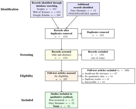
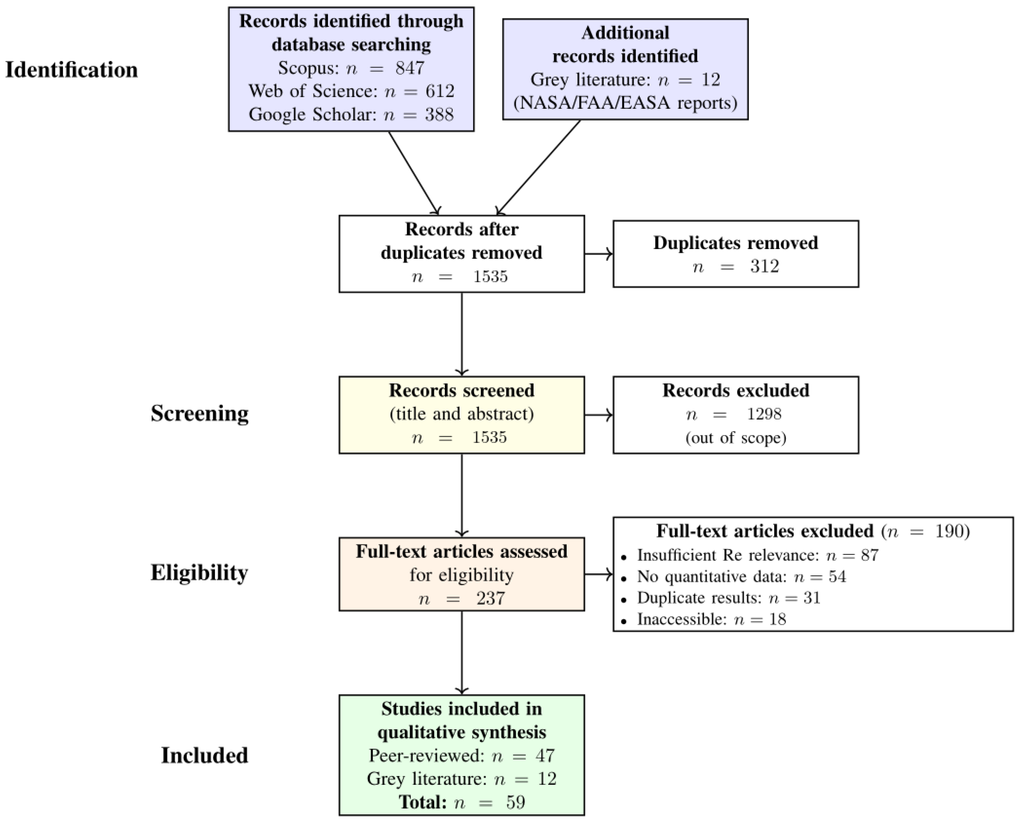
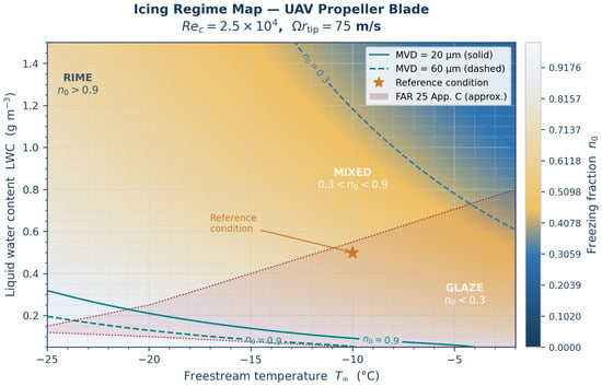
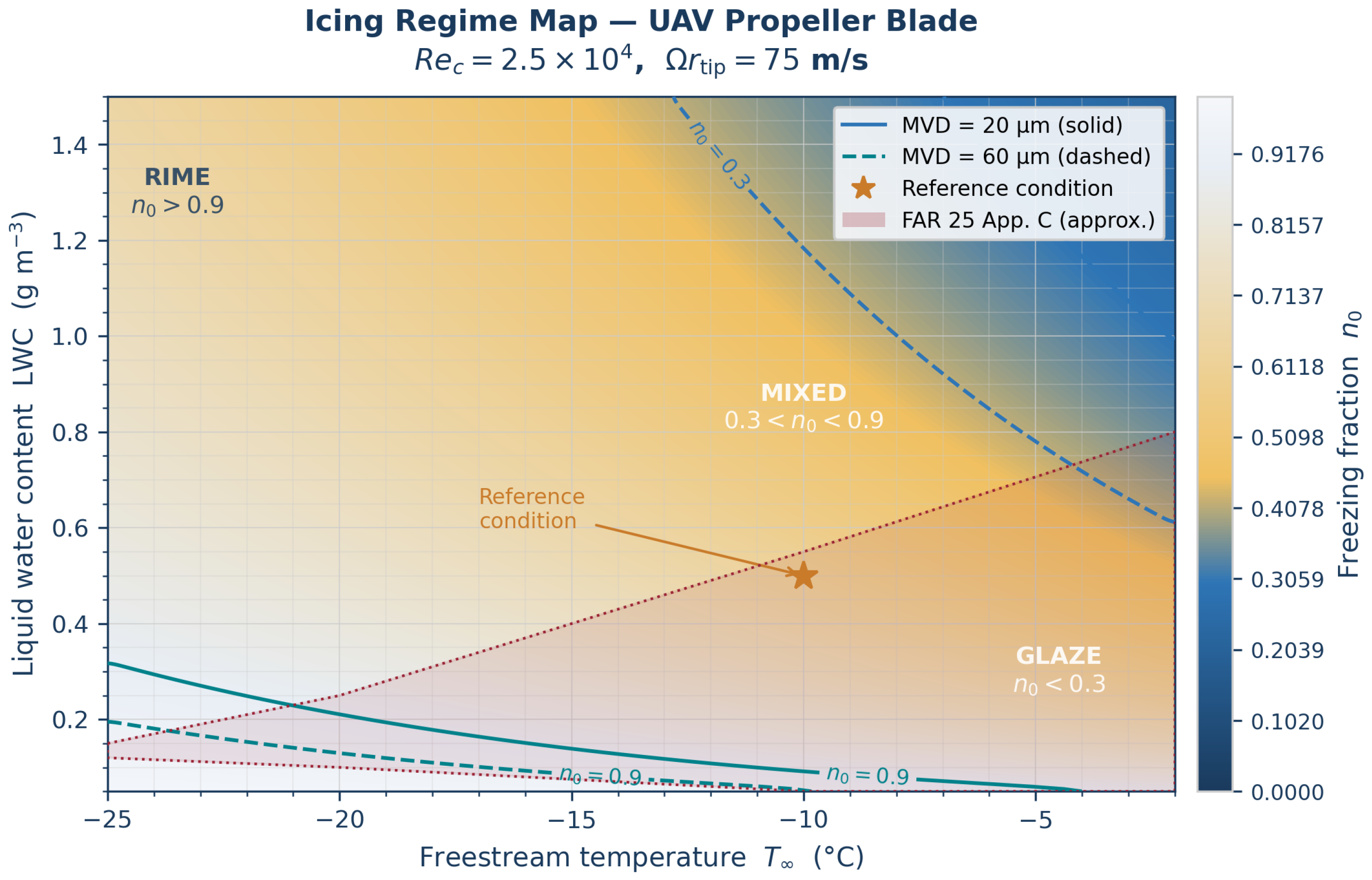
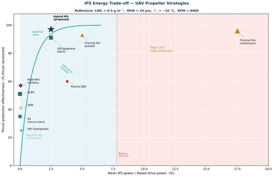
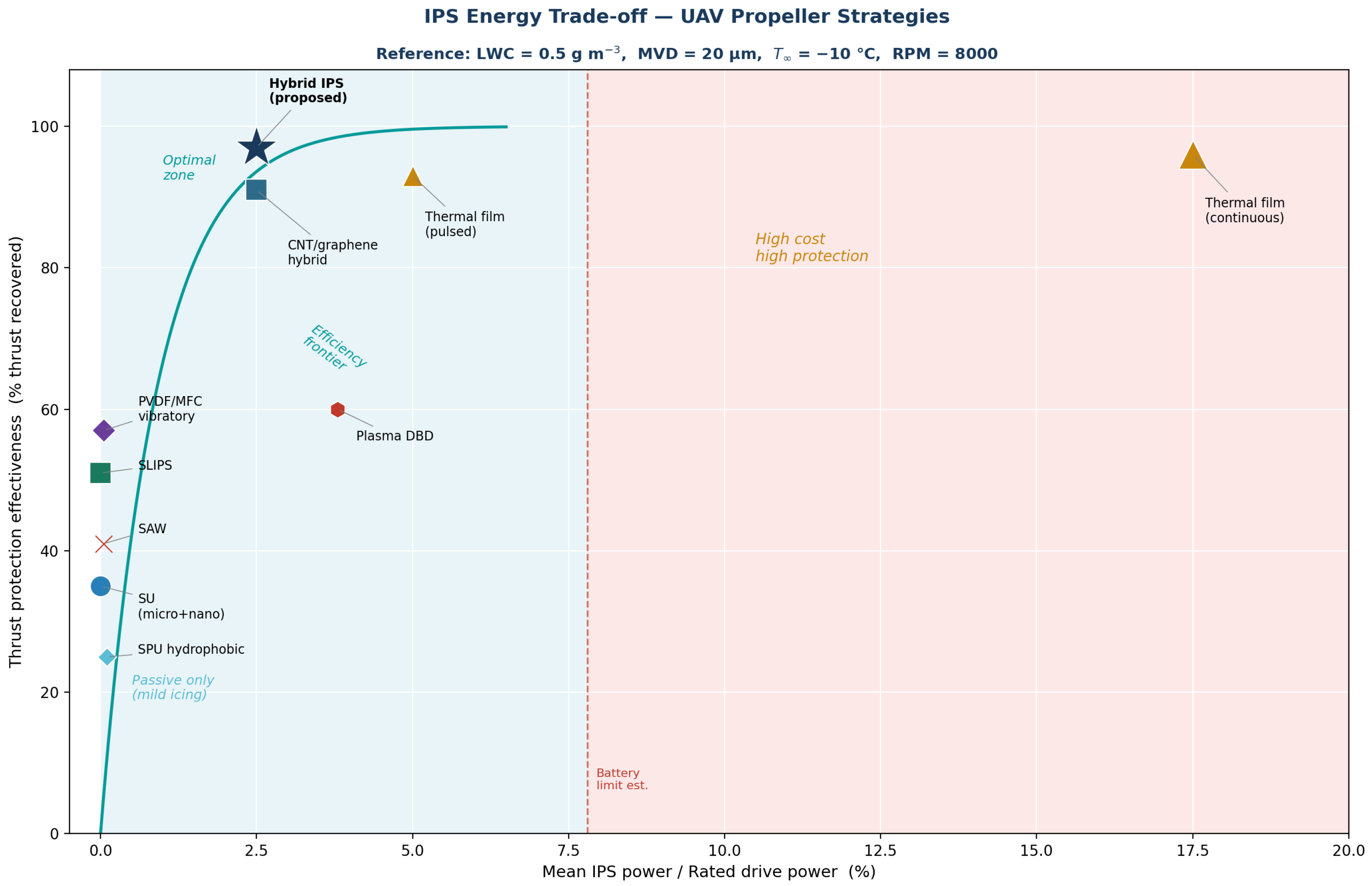
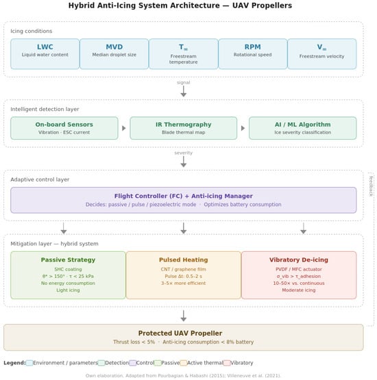
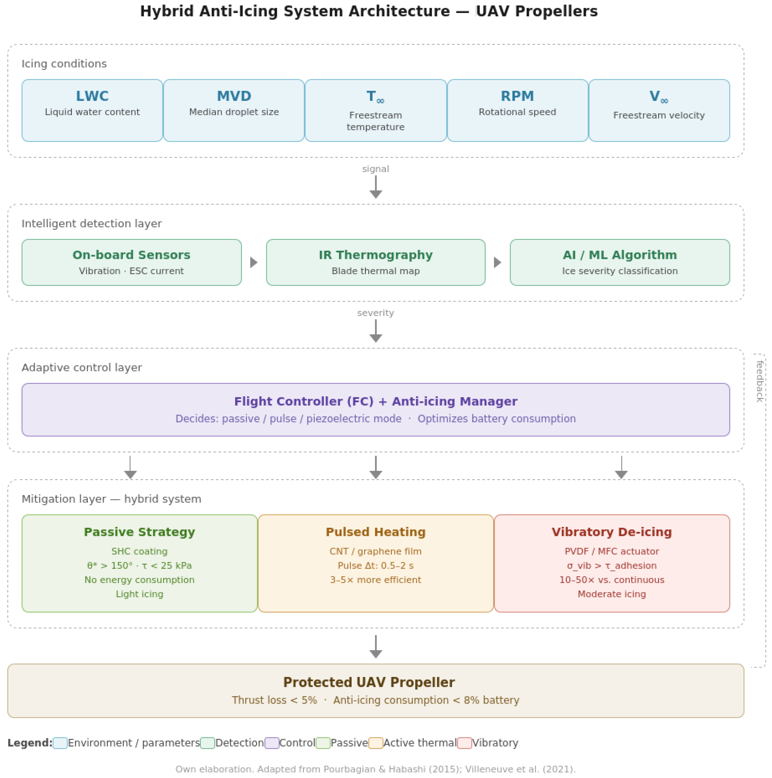

Disclaimer/Publisher’s Note: The statements, opinions and data contained in all publications are solely those of the individual author(s) and contributor(s) and not of MDPI and/or the editor(s). MDPI and/or the editor(s) disclaim responsibility for any injury to people or property resulting from any ideas, methods, instructions or products referred to in the content. |
© 2026 by the authors. Licensee MDPI, Basel, Switzerland. This article is an open access article distributed under the terms and conditions of the Creative Commons Attribution (CC BY) license.