


Abstract
Unmanned Surface Vehicles (USVs) operating in complex traffic conditions in island reef waters often require different types of algorithms. Therefore, selecting a dynamic path-planning algorithm with strong adaptability has become a new challenge. This paper proposes a dynamic adaptive path planning algorithm for USVs, incorporating an improved Dynamic Window Approach (DWA) with fuzzy logic and the International Regulations for Preventing Collisions at Sea (COLREGS). The algorithm is designed by integrating three key aspects: evaluation function, fuzzy control, and COLREGS. First, to enable USVs to approach the target point more safely and quickly during navigation, an additional target point attraction sub-function is introduced, extending the original evaluation function. Furthermore, to ensure robust dynamic path planning for USVs across various water environments, such as narrow channels, reef-laden waters, and open seas, fuzzy logic is integrated with the improved DWA algorithm. Since USVs must comply with COLREGS during navigation, the algorithm incorporates these regulations, enhancing the DWA algorithm with fuzzy logic to ensure compliance. Finally, simulation experiments validate the proposed algorithm, demonstrating that the planned paths are safer and more stable, ensuring the safe navigation of USVs in compliance with COLREGS.
1. Introduction
With the continuous advancement in intelligent ship technologies, significant breakthroughs have been realized in unmanned vessels [1,2]. Unmanned Surface Vehicles (USVs), due to their small size, high maneuverability, and rapid speed, have been widely utilized across various scenarios, including surface reconnaissance, search and rescue operations, and maritime transportation [3,4,5,6,7]. USVs are typically equipped with capabilities for environmental perception, planning, navigation, and learning [8,9]. During maritime navigation, USVs encounter various complex maritime environments. Therefore, effective path planning is crucial for ensuring the safe navigation of USVs in such environments, and the development of path planning algorithms reflects, to some degree, the level of intelligence of these vehicles [10,11].
Path planning [12] comprises both global static path planning [13] and local dynamic path planning [14]. Research on local dynamic path planning primarily focuses on how a USV, while following a globally determined static path, can successfully avoid static obstacles that were not identified during the global planning phase or dynamic obstacles that suddenly appear. This process involves adjusting the local trajectory, ultimately ensuring the USV safely arrives at the designated target.
As a challenging aspect of path planning, research on local dynamic path planning typically involves two types of approaches: traditional algorithms and hybrid algorithms. Traditional algorithms mainly encompass methods such as the Artificial Potential Field, Vector Field Histogram, and Dynamic Window Approach (DWA), among others. The Artificial Potential Field method, proposed by Khatib [15], is primarily used for mobile robot navigation. He proposed that the target point and obstacles are akin to charged surfaces, where the total potential creates a virtual force acting on the robot. This virtual force attracts the robot towards the target point while repelling it away from obstacles. The robot follows the negative gradient, avoiding obstacles and reaching the target point. The Artificial Potential Field algorithm has a simple structure, making it suitable for real-time control requirements. Building on this foundation, Zhu [16] proposed a potential field function construction without local minima, which can effectively escape local minima in specific environments, fundamentally addressing the issue of local minima. Wang [17] proposed an obstacle avoidance design based on an improved Artificial Potential Field algorithm, which reconstructs the repulsive field of obstacles and ultimately generates collision-free paths. The Vector Field Histogram method, proposed by Borenstein [18], addresses issues of instability and data oscillation caused by rapid changes in the force field of the Virtual Force Field method [19]. The Vector Field Histogram method retains the fast computation speed of the Virtual Force Field method while employing two-level data reduction techniques. This balances the computational load while preserving many details, allowing the robot to make smooth turns in narrow spaces. However, the algorithm initially did not account for the dimensions and kinematic characteristics of the mobile robot, which can result in situations where the robot is unable to execute the planned path. Borenstein [20] introduced the VFH+ algorithm, which implicitly incorporates the robot’s dimensions and kinematic characteristics by constructing a space that accounts for these factors. It binarizes the histogram and applies a cost function to evaluate candidate directions more precisely. Borenstein [21] proposed the VFH* algorithm, which can predict the potential consequences of choosing a particular direction, helping the robot to move closer to the target point during its motion. The Dynamic Window Approach, proposed by Fox [22], first generates multiple valid velocity combinations (linear and angular velocities) in a two-dimensional space. It then simulates each velocity combination over the sampling time to generate corresponding motion trajectories. Finally, an evaluation function selects the trajectory with the highest score, and the velocity corresponding to this trajectory is chosen as the robot’s motion speed for the next time step. Zhang [23] proposed an improved Dynamic Window Approach integrated with global path planning. By introducing the results of global path planning as reference trajectories, a new evaluation function was designed to ensure optimal trajectories. Directional evaluation sub-functions, smoothness evaluation sub-functions, and acceleration evaluation sub-functions were proposed to ensure the direction, smoothness, and speed of the motion, respectively. Li [24] proposed an improved Dynamic Window Approach that considers the relationship between the size of the mobile robot and the free space between obstacles. Laser rangefinders were used to enhance environmental perception and prediction capabilities, helping to avoid becoming trapped in U-shaped obstacles. Hybrid algorithms primarily combine traditional algorithms with other related approaches. Abdalla [25] proposed a method combining an improved Artificial Potential Field approach with fuzzy logic. It resolves the local minima problem of the classic Artificial Potential Field method. It employs a fuzzy logic controller for the motion control of the mobile robot. Particle swarm optimization is used to optimize the membership functions of the fuzzy logic controller. Babinec [26] proposed the VFH*TDT algorithm, which represents a new improvement on the VFH+ and VFH* methods. The algorithm incorporates the motion information of dynamic obstacles, calculates the future positions of obstacles, and performs predictions at each node of the lookahead tree. Dobrevski [27] proposed a new deep convolutional neural network that dynamically predicts the parameters of the Dynamic Window Approach evaluation function based on sensor data.
When USVs navigate through narrow waters, reef areas, or busy traffic zones, different strategies must be employed. This is crucial for the flexible control of USVs in obstacle avoidance. Therefore, the dynamic adjustment of parameters for various algorithms has become a necessity. Adaptive path planning algorithms have emerged in response to this need. The method proposed by Abdalla [25], which combines an improved Artificial Potential Field approach with fuzzy logic, enables adaptive path planning. Dobrevski [27] achieves adaptability by dynamically predicting the parameters of the Dynamic Window Approach evaluation function using a deep convolutional neural network. Zhang [28] achieves adaptability through an online parameter adaptive Dynamic Window Approach, automatically adjusting the weights of the evaluation function based on the size of the alternative velocity space and the distance of the mobile robot to the target point.
Given the complex and variable nature of maritime traffic environments and the need to enhance the regulation and safety of USVs, integrating the International Regulations for Preventing Collisions at Sea (COLREGS) with dynamic path planning has become a new trend. Li [29] combined an improved particle swarm optimization algorithm with the Dynamic Window Approach to design an obstacle avoidance algorithm that complies with COLREGS. Huang [30] improved the A* algorithm and combined it with a multi-target Artificial Potential Field approach and COLREGS. Li [31] combined an improved Artificial Potential Field method with a nonlinear model predictive control algorithm, proposing a collision avoidance decision support scheme that considers vessel maneuverability and COLREGS.
In previous studies [32], it has been observed that dynamic path planning requires consideration of both path and velocity planning, with a high demand for real-time performance. Therefore, selecting an appropriate dynamic path-planning algorithm is crucial. Traditional dynamic path planning algorithms, however, tend to have an overly simplistic structure, rendering them inadequate for handling complex and dynamic scenarios. This necessitates the optimization of algorithms to enhance adaptability. Moreover, in algorithms integrated with COLREGS, few researchers have employed approaches related to robot dynamics to impose limitations on linear and angular velocities. This is because applying the first layer of constraints on linear and angular velocities, followed by a second layer of constraints based on COLREGS, presents considerable implementation challenges. Additionally, when real-time planning algorithms are integrated with COLREGS, significant variations in the vessel’s heading often arise. Therefore, this paper proposes an improved DWA combined with fuzzy logic and COLREGS for the dynamic adaptive path planning of USVs, ensuring safe navigation. The main contributions of this paper are as follows:
- The evaluation function of the traditional DWA algorithm has been optimized, and a target point attraction sub-function has been introduced, allowing the USV to approach the target point more safely and quickly during navigation.
- By combining fuzzy logic with the improved DWA algorithm, the dynamic path planning of the USV demonstrates strong robustness in various water environments, including narrow waters, island waters, and open waters.
- By introducing COLREGS, a fuzzy improved DWA algorithm combined with COLREGS has been designed for USV dynamic path planning, ensuring that the USV adheres to COLREGS during navigation.
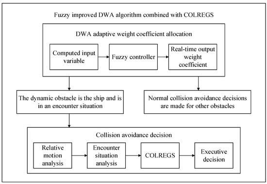
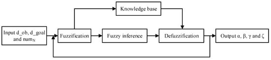
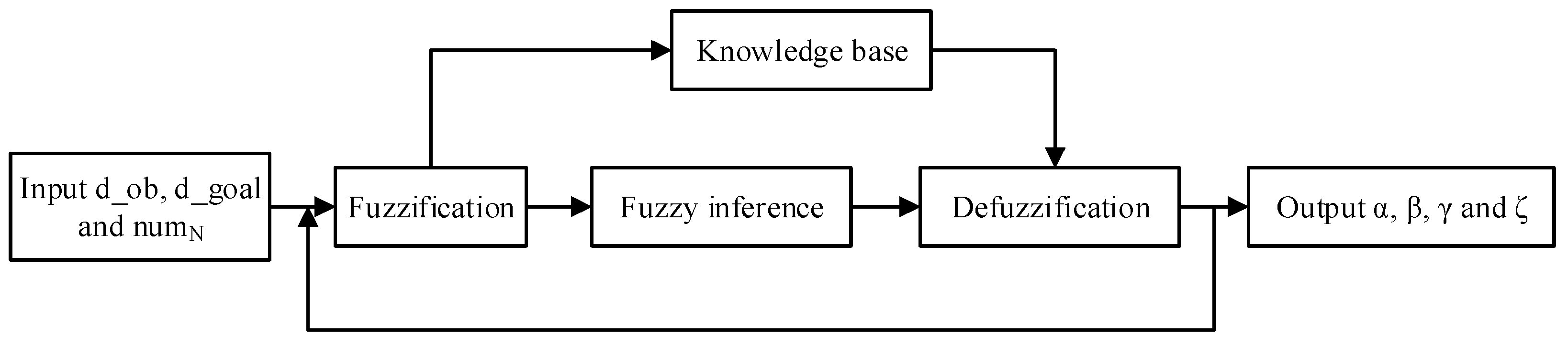
The design of the algorithm is shown in Figure 1.
Figure 1.
Fuzzy improved DWA algorithm combined with COLREGS.
The remainder of this paper is organized as follows:
Section 2 describes the USV motion model and traffic constraints. Section 3 presents the fuzzy improved DWA algorithm. Based on Section 2 and Section 3, Section 4 designs the fuzzy improved DWA algorithm combined with COLREGS. Section 5 validates the fuzzy improved DWA algorithm and the fuzzy improved DWA algorithm combined with COLREGS through algorithm implementation and analysis, fully demonstrating the advantages of the proposed algorithm in terms of safety and stability. Finally, Section 6 provides a brief summary and review of the overall work.
2. USV Motion Model and Traffic Constraints
2.1. USV Motion Model
The motion of a USV follows six degrees of freedom, making its motion model more complex. To standardize the motion model of the USV, the following assumptions are usually made:
- The USV is considered a rigid body with a constant mass, and this mass is distributed uniformly across the vessel.
- The USV is symmetric about its longitudinal plane.
- The USV operates in a sea-level environment where gravitational acceleration, air density, and seawater density are constant values.
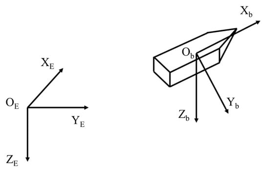
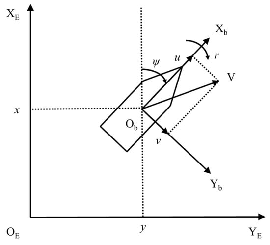
When analyzing the motion model through the use of coordinate systems, it is typically necessary to establish two types of coordinate systems. These include the geodetic coordinate system and the USV coordinate system.
- Geodetic coordinate system
Select the coordinate system OE-XEYEZE as the geodetic coordinate system, define the coordinate system origin OE fixed on the earth’s surface, the XE axis positive direction points to the north of the earth, the YE axis positive direction points to the east of the earth, and the ZE axis positive direction points to the center of the earth.
- 2.
- USV coordinate system
Select the coordinate system Ob-XbYbZb as the USV coordinate system, define the coordinate system origin Ob fixed at the center of gravity of the USV, with the Xb axis positive direction pointing towards the bow, the Yb axis positive direction pointing towards the starboard side, and the Zb axis positive direction is perpendicular to the deck of the USV, pointing downward.
The geodetic coordinate system and the USV coordinate system are shown in Figure 2.
Figure 2.
Geodetic coordinate system and the USV coordinate system.
Considering that the motion and orientation of USVs involve six degrees of freedom, it is necessary to define motion parameters to describe the orientation information of the USV accurately. The specific motion variables and their corresponding symbols are shown in Table 1.
Table 1.
Motion variables and symbols.
The contents of the table are briefly explained below [33]. represents the projection of the USV position in the geodetic coordinate system and describes the displacement of the origin of the USV coordinate system in the direction of the OEXE, OEYE, and OEZE axes, respectively. represents the attitude information of the USV, describing roll, pitch, and yaw, respectively, and is positive when the ObXb axis is rotated clockwise and negative otherwise. represents the linear velocity of the USV projected on the axis of ObXb, ObYb, ObZb, i.e., the speed of surge, sway, and heave. represents the angular velocity of the USV projected on the axis of ObXb, ObYb, ObZb, i.e., the angular velocity of roll, pitch, and yaw. represents the force acting on the ObXb, ObYb, ObZb axes in the USV coordinate system. represents the torque acting on the ObXb, ObYb, ObZb axes in the USV coordinate system.
Considering the complexity of the six degrees of freedom model for USVs, it is difficult to discuss local dynamic path planning algorithms based on this model. Therefore, to facilitate subsequent simulation studies of USVs, the following simplifications are typically applied. Only the motion of the USV in the horizontal plane is considered, retaining the degrees of freedom for surge, sway, and yaw. Define to be the position and attitude vector of the USV. Define as the surge, sway, and yaw vectors of the USV, the USV horizontal motion model is shown in Figure 3.
Figure 3.
USV horizontal motion model.
2.2. USV Traffic Constraints
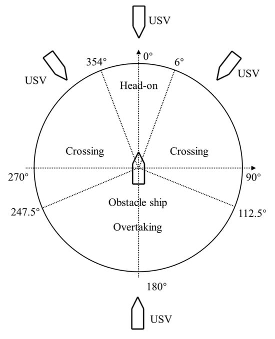
To ensure the safe navigation of USVs, three encounter situations are defined according to COLREGS. When dividing the encounter state, it is necessary to divide it according to the heading Angle between the USV and other ships. At and , the USV is considered to be in a head-on state with other ships. At and , the USV is considered to be in a crossing state with other ships. At , the USV is considered to be in overtaking with other ships. The specific division is shown in Figure 4.
Figure 4.
Three kinds of encounter state division.
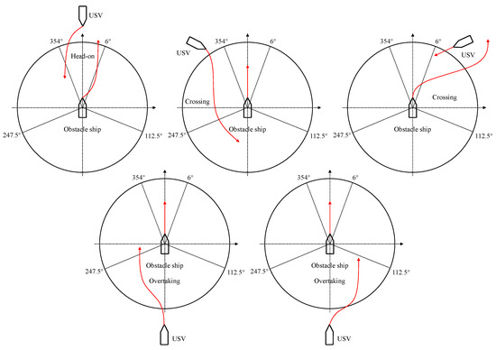
For head-on, crossing, and overtaking, the collision avoidance rules proposed by COLREGS are shown in Figure 5.
Figure 5.
Three types of collision avoidance rules.
When USVs perform collision avoidance according to COLREGS, the following principles are typically observed:
- Head-on: No distinction is made between a giving-way ship and a straight ship; both ships must turn to the right to avoid collision until the end of the encounter.
- Crossing: When observed that the other ship is on the starboard side of the ship, the ship shall turn to the right as a giving way ship, and the other ship shall remain sailing as a straight ship until the end of the encounter. When it is observed that the other ship is on the port side of the ship, the ship remains on course as a straight ship, and the other ship, as a giving way ship, shall turn to the right until the end of the encounter.
- Overtaking: The situation is divided into port overtaking and starboard overtaking. When this ship overtakes the other ship from the port side of the other ship, my ship needs to turn left to avoid it, and the other ship remains under sail until the end of the encounter. When this ship overtakes his ship from his starboard side, my ship needs to turn to the right to avoid it, and the other ship remains under sail until the end of the encounter.
- Note that in special cases, you can communicate with other ships to take special strategies to deal with the situation or directly take special strategies to deal with the situation.
Since the application scenario of the algorithm designed in this paper is USVs, only the case of USVs as a collision avoidance ship is considered, and special strategies are adopted to deal with the encounter situation in special cases.
3. Fuzzy Improved DWA Algorithm
3.1. The Original DWA Algorithm
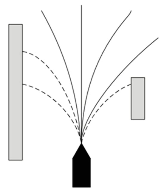
The DWA algorithm is derived from the dynamic model of the robot and offers significant advantages for controlling high-speed moving robots. Dissimilar to previous dynamic path planning algorithms, the DWA algorithm operates based on velocity control. After eliminating trajectories with collision risks, the trajectory with the highest evaluated linear and angular velocities, selected from the velocity sampling space, is used as the robot’s linear and angular velocities in the next step to achieve motion control. The schematic diagram is shown in Figure 6, where the dark pentagon represents the USV, the light gray area represents obstacles, the solid black line represents the allowable trajectory, and the dashed black line indicates the unsafe trajectory that needs to be avoided.
Figure 6.
Principle of the DWA algorithm.
The velocity space of the DWA algorithm is subject to the following constraints:
First, the set of velocities that USV can achieve by itself (linear velocity , angular velocity ) . As shown in Equation (1):
where, is the minimum linear velocity attainable by USV, is the maximum linear velocity attainable by USV, is the minimum angular velocity attainable by USV, and is the maximum angular velocity attainable by the USV.
Second, the USV is limited by the speed (linear and angular velocity) set from the motor. As shown in Equation (2):
where, and represent the current USV linear velocity and angular velocity, respectively, and and represent the maximum linear acceleration and maximum angular acceleration provided by the USV motor, respectively.
Finally, in order to keep a safe distance between the USV and obstacles during driving and avoid collision, a limiting set of speeds (linear speed and angular speed) is required. As shown in Equation (3):
where is the distance from the curvature corresponding to the velocity combination to the nearest obstacle, and and represent the linear and angular acceleration of the USV fracture, respectively.
The final sampling space set of the USV is the intersection of , and , namely .
It is feasible for DWA to predict multiple groups of trajectories, and the optimal path should be selected according to the evaluation function. The design criterion of the evaluation function requires the USV to travel to the target point without collision and conform to the USV motion law. In general, the evaluation function of the traditional DWA algorithm is shown in the Equation (4):
is the subfunction of direction angle evaluation, indicating the minimum angle at which the USV forward direction turns to the USV direction of the target point at the current speed. is the subfunction of safety distance evaluation, representing the distance between the USV and the nearest obstacle intersected by the curvature of the arc corresponding to the current linear velocity and angular velocity under the current velocity. is the velocity evaluation subfunction, representing the progress of the USV on the corresponding trajectory. In order to ensure the continuity and smoothness of the three trajectories, the above three evaluation subfunctions need to be normalized. is the smoothing function, , , are the weighting coefficients of the above three evaluation subfunctions, and the value range is usually .
3.2. Optimization of the DWA Algorithm Evaluation Function
In order to make the USV approach the target point more safely during the driving process, a target point traction evaluation subfunction is added to the evaluation function of the original DWA algorithm. The target point traction evaluation subfunction represents the distance between the USV and the target point at the current speed. The current speed is evaluated by distance, and a smaller distance means a better path and a better current speed. As shown in Equation (5):
where is the position of the USV at time , and is the position of the target point. represents the distance between the USV and the target point and is in a constantly updated state at different times. To sum up, the original evaluation function is adjusted. As shown in Equation (6):
Here, the weight coefficient for the heading angle evaluation sub-function is , the weight coefficient for the safety distance evaluation sub-function is , the weight coefficient for the speed evaluation sub-function is , and the weight coefficient for the target point attraction evaluation sub-function is . , , , are the weighting coefficients of the above four evaluation subfunctions, and the value range is usually . It is necessary to assign reasonable weight coefficients to the four parts. Therefore, this paper introduces fuzzy logic to self-adaptively calculate the weights of each subfunction in the evaluation function so as to obtain the optimal control line velocity and angular velocity parameters of the USV.
3.3. Fuzzy Improved DWA Algorithm
In this part, the dynamic allocation of weight coefficients , , , and of the improved DWA algorithm will be realized by a fuzzy logic controller according to different environment information.
A complete fuzzy controller usually consists of the following four parts [34,35]:
- The definition of fuzzy control input variable and output variable.
- Fuzzy processing of variables.
- The design of the knowledge base [36].
- The choice of defuzzification method.
The specific structure of the fuzzy logic controller [37] is shown in Figure 7:
Figure 7.
The fuzzy improved DWA algorithm.
3.3.1. Selection and Definition of Input Variables for the Fuzzy Controller
Since the updated evaluation function includes the direction angle evaluation subfunction, safety distance evaluation subfunction, velocity evaluation subfunction, and target point traction evaluation subfunction, , and are designed as input variables of the fuzzy controller in the fuzzy improved DWA algorithm.
Define the input variable to represent the distance of the USV from the nearest obstacle. As shown in Equation (7):
Define the input variable d goal to represent the distance between the USV and the target point. As shown in Equation (8):
The position of the USV at time is , the position of the nearest obstacle is , and the position of the target point is .
In order to distinguish the degree of collision risk of obstacles around the USV, the circular area with the center of mass of the USV as the center of the circle and as the radius is defined as the collision risk domain of the USV. It is considered that obstacles in this domain have collision risk to the unmanned craft, and the field is divided into sectors clockwise from the current orientation of the unmanned craft. If there is an obstacle in the sector, the sector is considered to be affected by the obstacle. Thus, the input variable is defined to represent the number of sectors affected by obstacles in the USV domain.
3.3.2. Design of Membership Functions
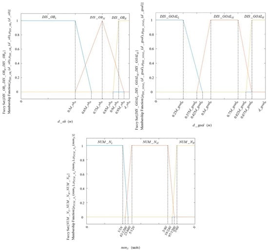
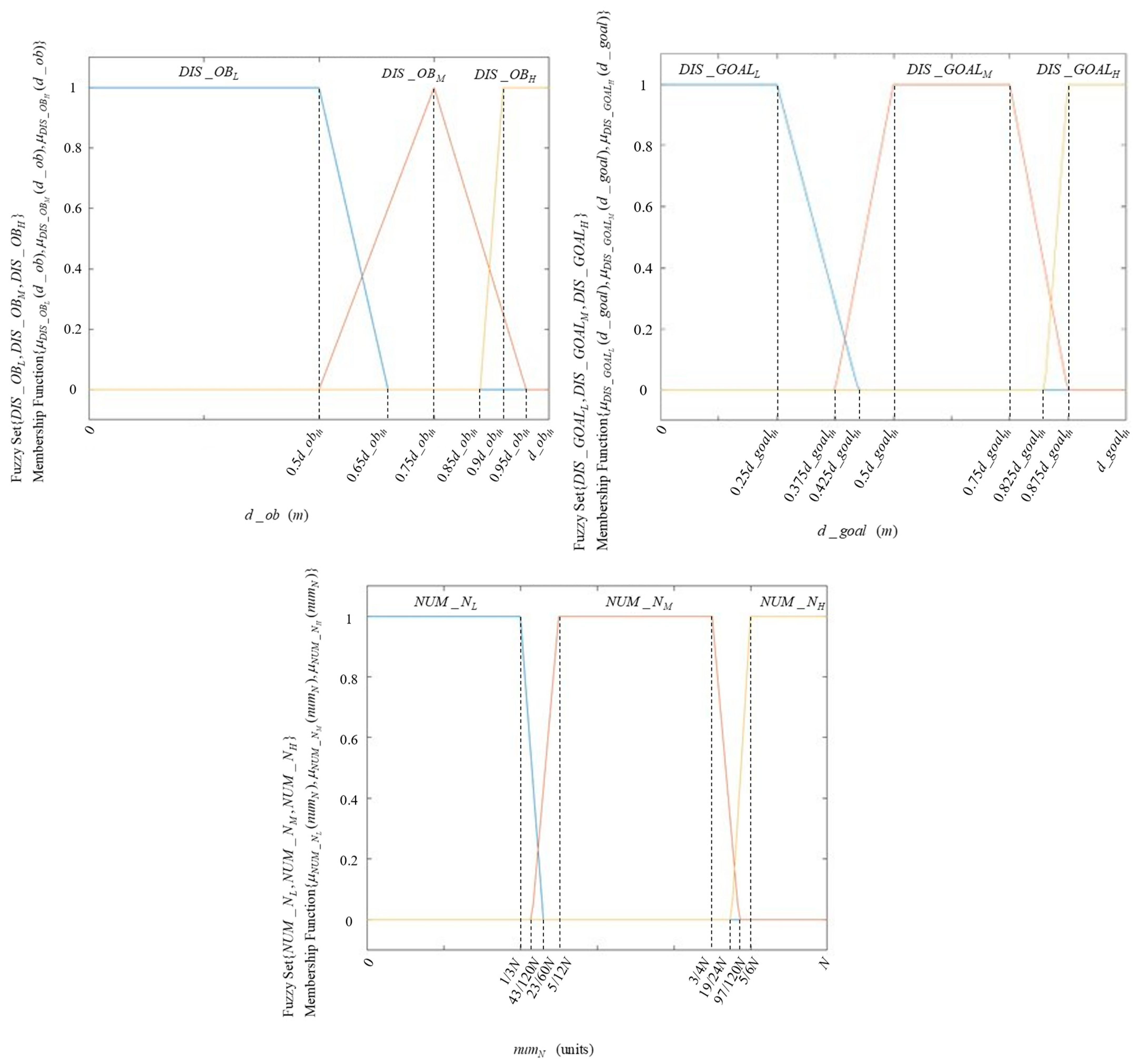
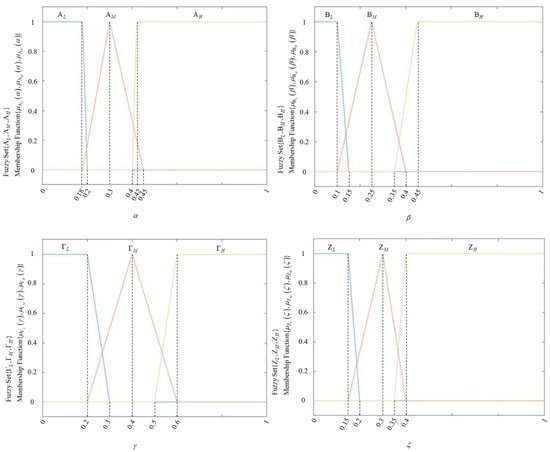
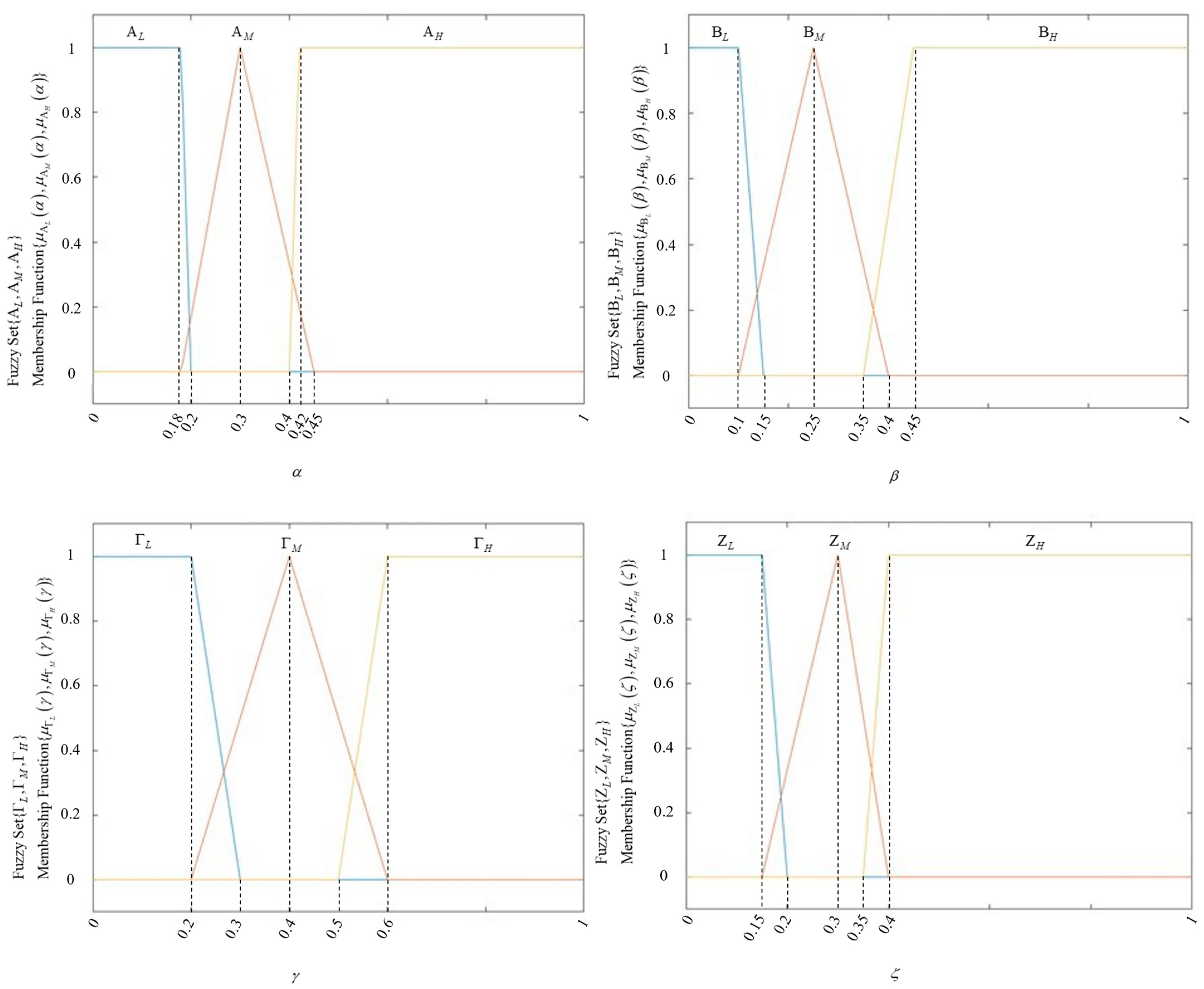
Based on statistical analysis of real-world conditions and considering that abrupt changes in speed or position do not occur during USV motion, the input and output variables of the fuzzy controller designed in this paper are defined over continuous domains. For the design of the membership functions, a combination of trapezoidal and triangular functions is considered.
The input variables are fuzzified, and fuzzy sets are defined, as shown in Table 2.
Table 2.
Input fuzzy variables information table.
The fuzzy variable interval needs to be set when the distance between the input fuzzy variable USV and the nearest obstacle is used. As shown in Equation (9):
where, when , the distance between the USV and the nearest obstacle exceeds the collision safety threshold , indicating that the USV is far away from the obstacle.
The fuzzy variable interval needs to be set when using the distance between the input fuzzy variable USV and the target point. As shown in Equation (10):
where, when , the distance between the USV and the target point exceeds the distance threshold , indicating that the USV is currently far from the target point.
Membership function images of input fuzzy variables , , are shown in Figure 8.
Figure 8.
Input fuzzy variable membership function graph.
The output variables are fuzzified, and fuzzy sets are defined, as shown in Table 3.
Table 3.
Output fuzzy variables information table.
Membership function images of output fuzzy variables , , , and are shown in Figure 9.
Figure 9.
Output fuzzy variable membership function graph.
3.3.3. Design of Fuzzy Rules
The fuzzy rule is the key to the fuzzy controller, which directly determines the efficiency and quality of the fuzzy controller. Generally, the establishment of fuzzy rules needs to rely on the accumulation of technical knowledge and practical experience of relevant technical personnel. The formulation of fuzzy controller rules designed in this paper needs to consider the evaluation function of the dynamic window algorithm. Considering the priority of weight coefficients , , , and in the evaluation function at different times and in different scenarios, the fuzzy rules of the fuzzy controller are designed as follows.
For the developed fuzzy controller, a set of 27 rules is assigned for all the different cases, and only a portion of the rules are shown here, as follows:
If ( is ) and ( is ) and ( is ) then ( is ) ( is ) ( is ) ( is )
If ( is ) and ( is ) and ( is ) then ( is ) ( is ) ( is ) ( is )
If ( is ) and ( is ) and ( is ) then ( is ) ( is ) ( is ) ( is )
If ( is ) and ( is ) and ( is ) then ( is ) ( is ) ( is ) ( is )
If ( is ) and ( is ) and ( is ) then ( is ) ( is ) ( is ) ( is )…
The complete 27 fuzzy rules are shown in Table 4.
Table 4.
Complete 27 fuzzy rules.
In this paper, the Mamdani fuzzy system is selected for inference, and the desired fuzzy vector is obtained. Finally, the gravity center method is used to defuzzify the obtained vector, and the specific output variables , , , and are obtained.
4. Fuzzy Improved DWA Algorithm Combined with COLREGS
To ensure that the USV adheres more closely to maritime traffic rules during navigation, COLREGS is now integrated into the fuzzy improved DWA algorithm.
4.1. Calculation of Relative Motion Parameters
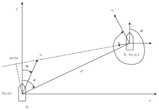
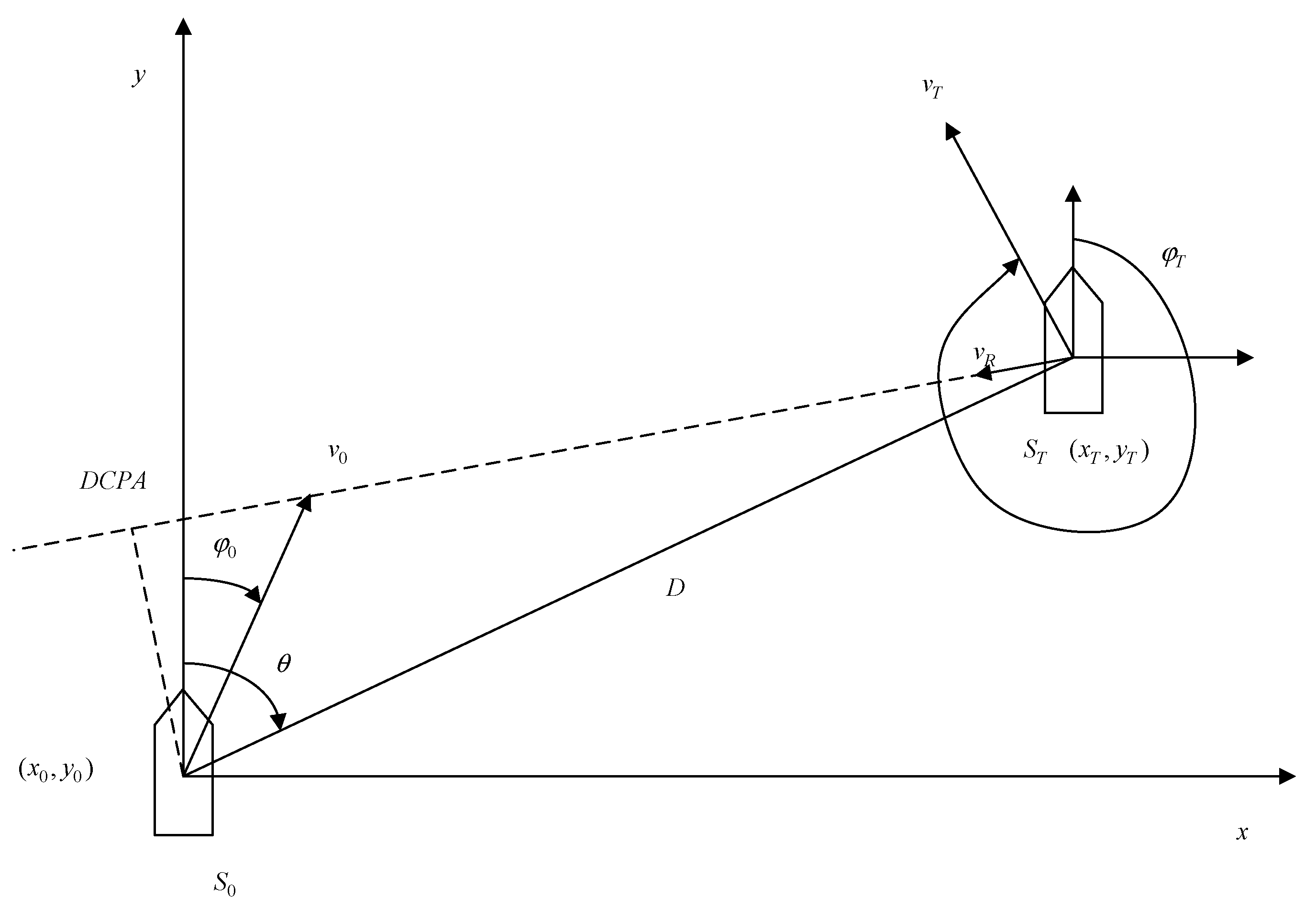
Assume that the geographic coordinates of the USV S0 in the global coordinate system are , the speed is , and the course is . The geographical coordinates of the obstacle vessel ST are , the sailing speed is , and the heading . The relative motion of the two is shown in Figure 10.
Figure 10.
Relative motion condition.
The velocity components of the USV and the obstacle vessel along the and axes. As shown in Equations (11) and (12):
The components of the relative velocity along the and axes. As shown in Equation (13):
The magnitude and heading of the relative motion velocity. As shown in Equations (14) and (15):
The specific formula for α is shown in Equation (16):
The relative distance between the USV and the obstacle vessel is shown in Equation (17):
The true bearing of the obstacle vessel relative to the USV is shown in Equation (18):
The specific formula for is shown in Equation (19):
The specific formula for the relative bearing is shown in Equation (20):
The specific formula for the crossing angle between the heading of the obstacle vessel and the USV is shown in Equation (21):
The specific formula of nearest encounter distance DCPA is shown in Equation (22):
The specific formula of the minimum encounter time TCPA is shown in Equation (23):
The specific formula of ship speed ratio is shown in Equation (24):
4.2. The Process Design and Decision Model of Fuzzy Improved DWA Algorithm Combined with COLREGS
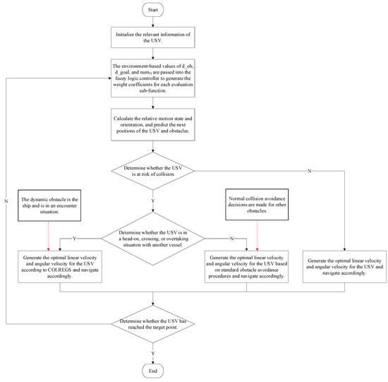
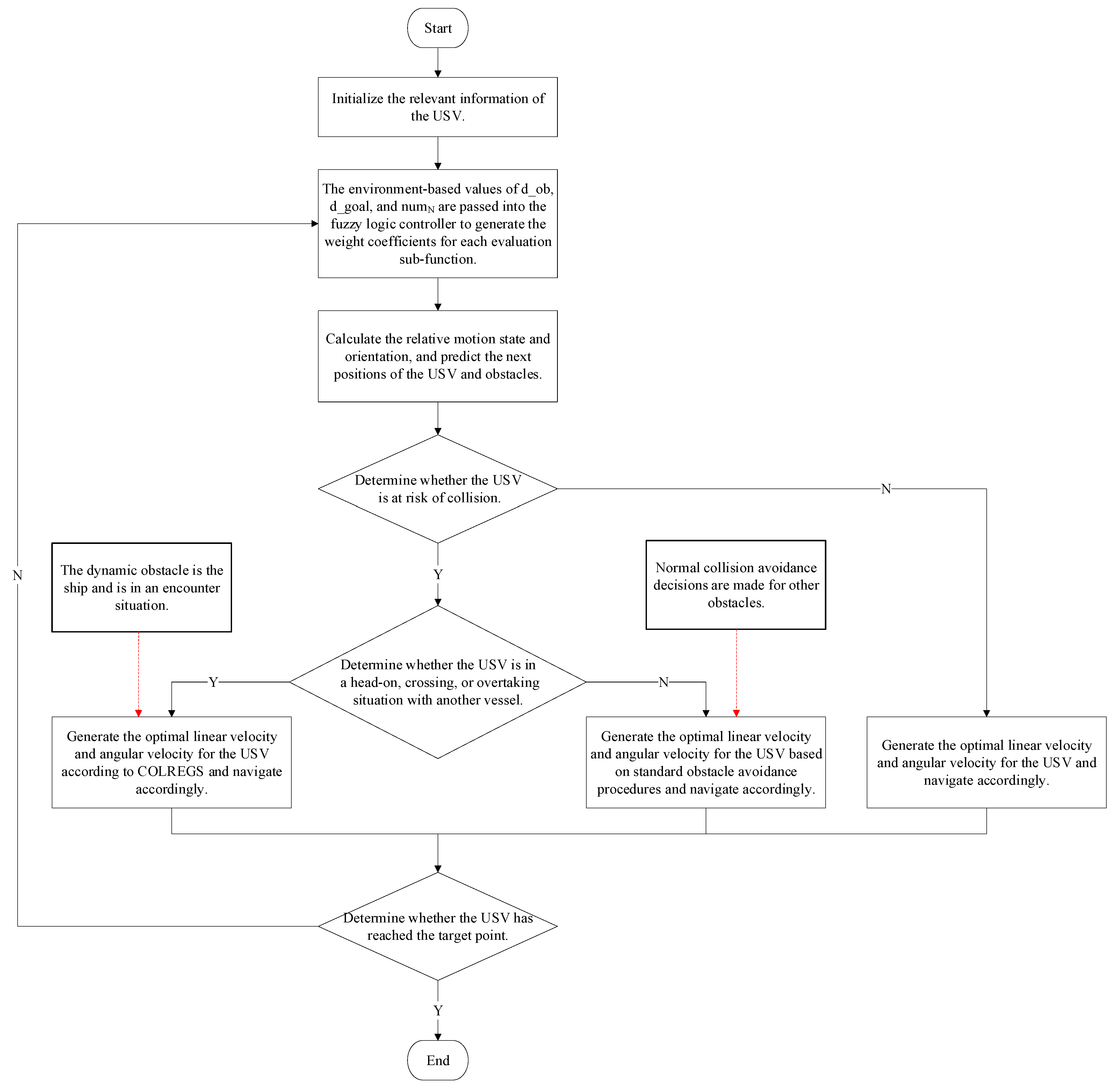
In the course of navigation, the USV needs to continuously calculate the relationship between the surrounding ships and obstacles so as to make corresponding obstacle avoidance decisions. Therefore, the process design is shown in Figure 11.
Figure 11.
Algorithm process design.
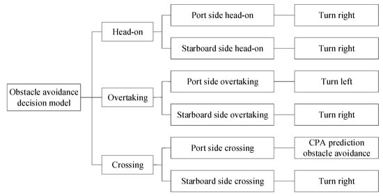
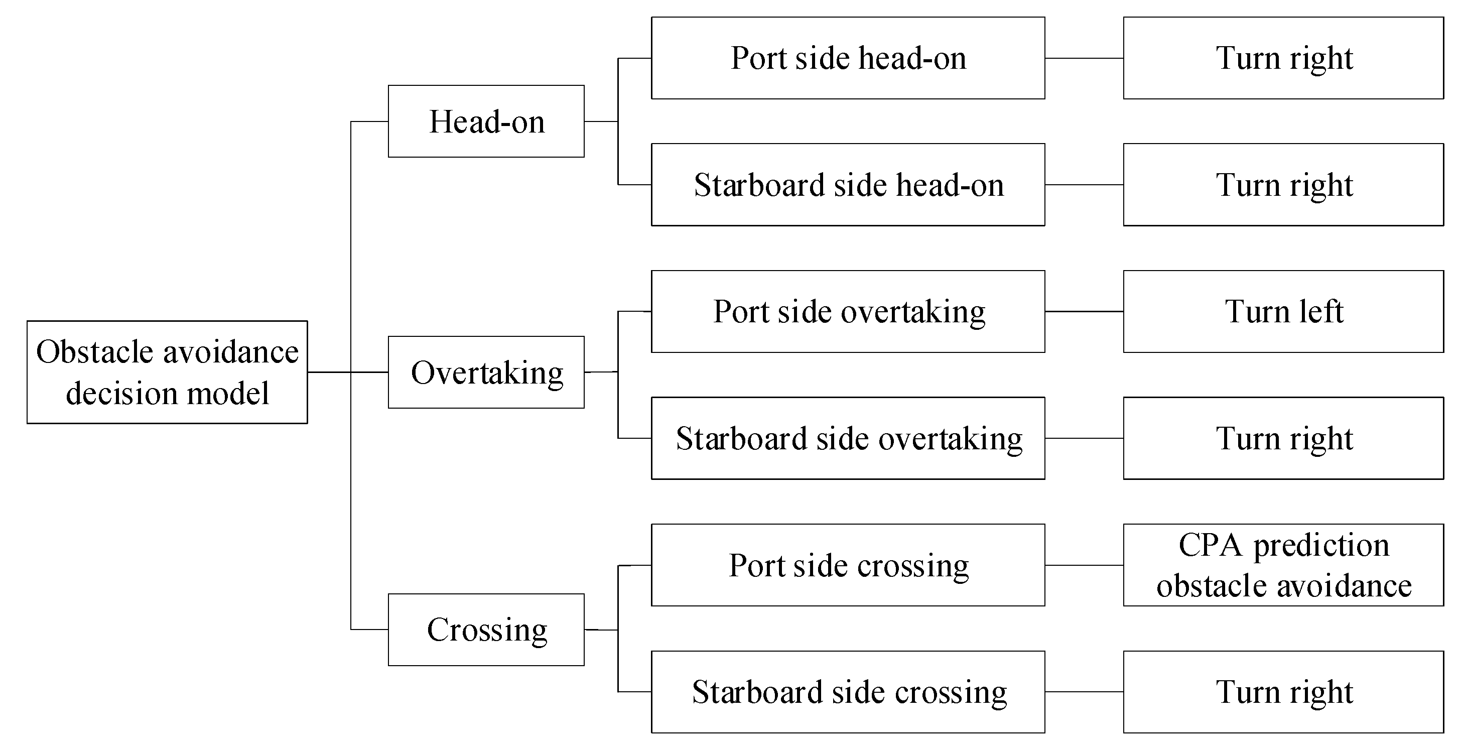
In the subsequent algorithm tests, only scenarios where the USV is the giving way ship are considered. The complete decision model is shown in Figure 12.
Figure 12.
Decision model.
5. Algorithm Implementation and Analysis
To validate the fuzzy improved DWA and the fuzzy improved DWA algorithm combined with COLREGS, virtual scenarios and case studies were designed for testing. Several representative experiments are selected for brief explanation and analysis. In the experiment, the vessel is abstracted as a point mass.
5.1. Experiments of the Fuzzy Improved DWA Algorithm
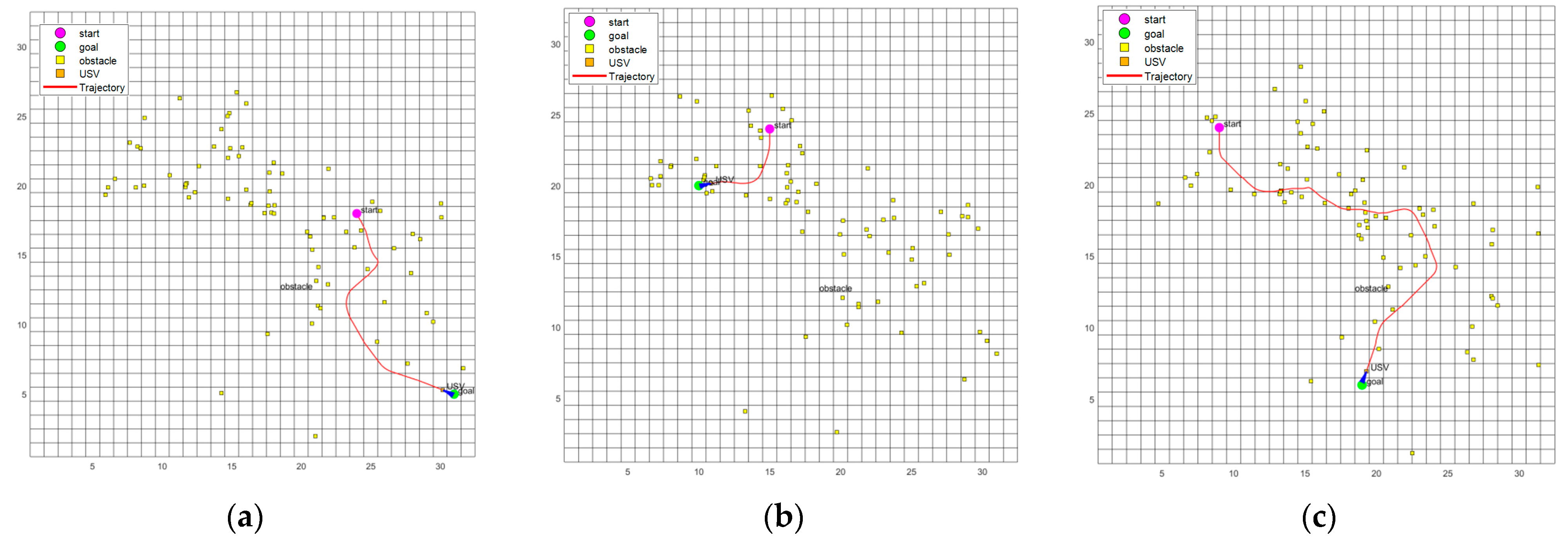
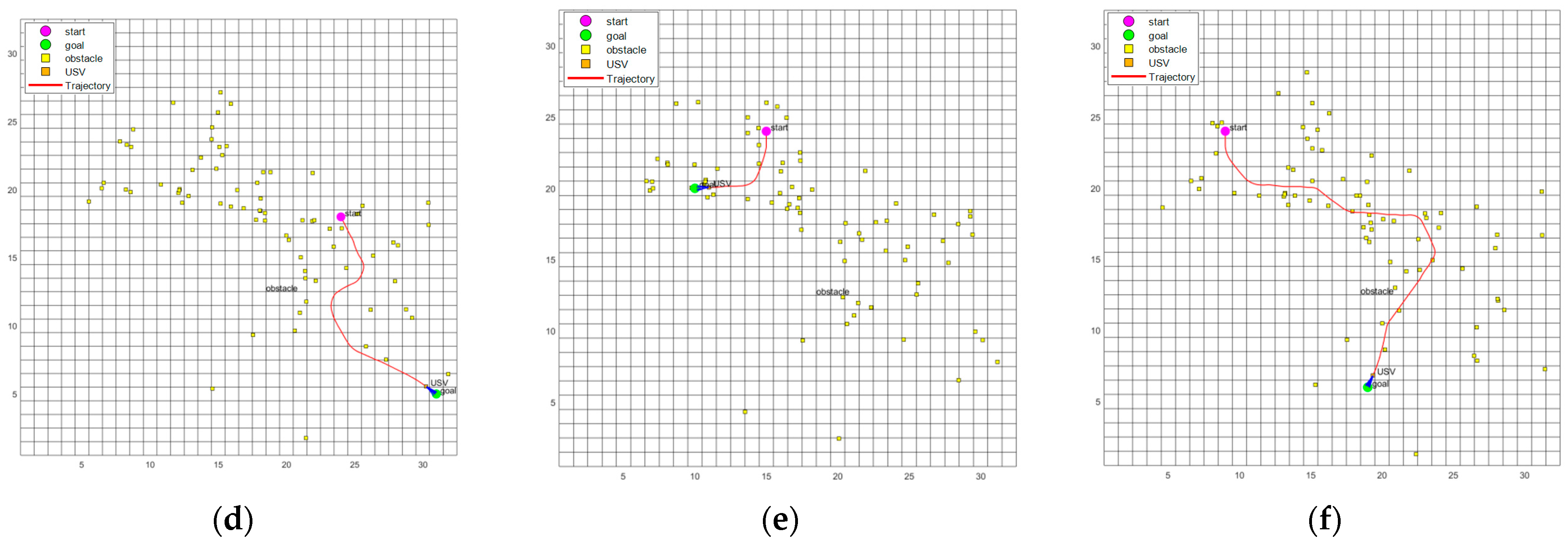
To validate the fuzzy improved DWA, both static and dynamic–static mixed scenarios were selected. The DWA and fuzzy improved DWA using alternative membership functions, and the fuzzy improved DWA were compared with each other.
The USV information needs to be initialized before the simulation experiment. The initialization parameter settings are shown in Table 5.
Table 5.
Initialize parameter settings.
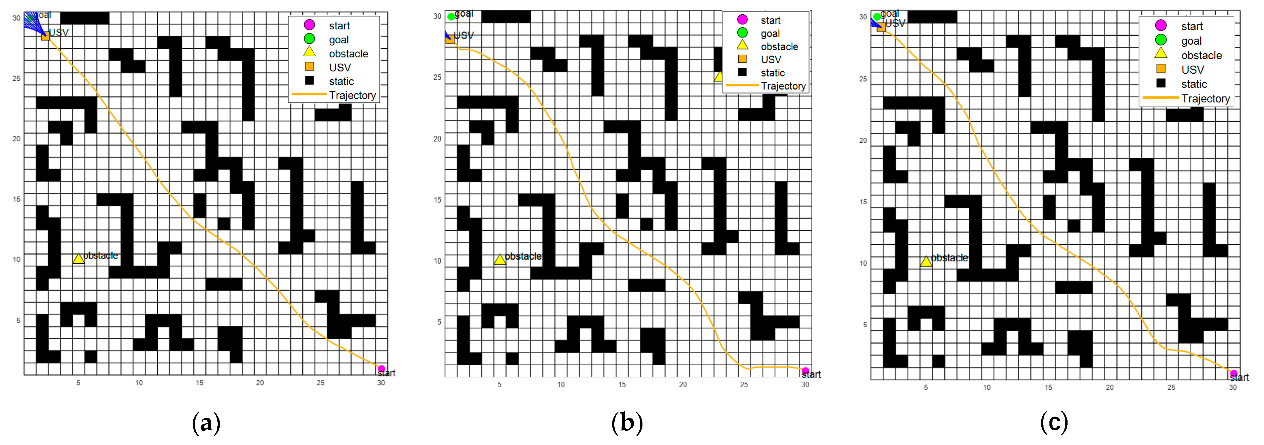
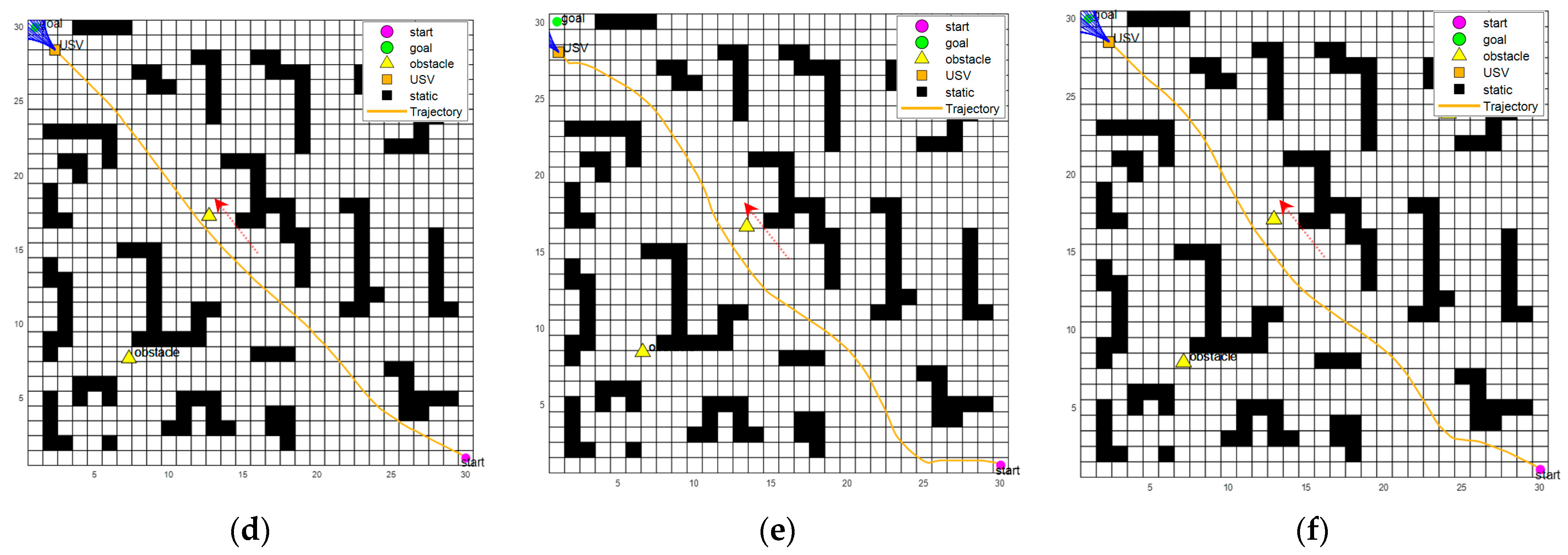
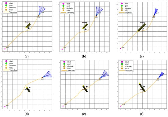
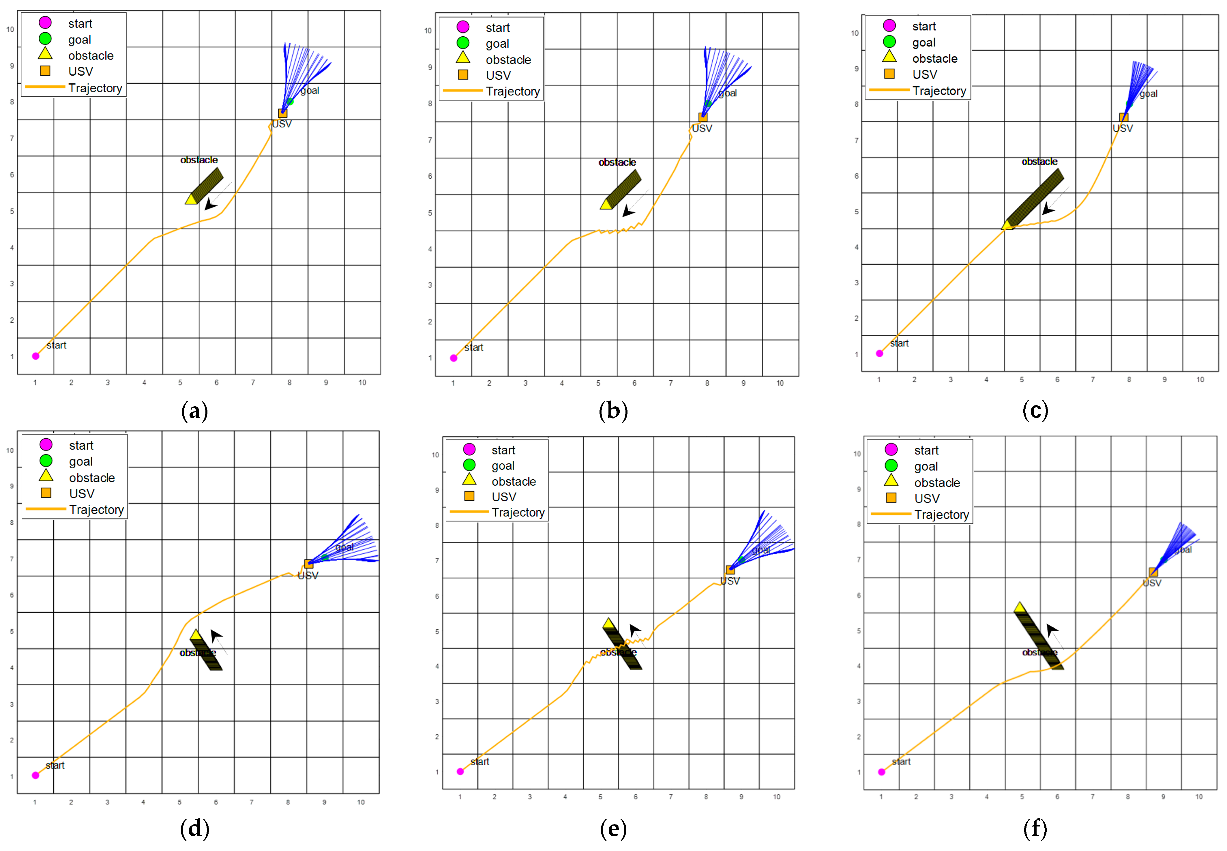
In both the static and dynamic–static mixed scenarios, corresponding grid-based environments were set up. The grid size was set to . The grid containing the magenta circle labeled “start” represents the starting point, while the grid containing the green circle labeled “goal” represents the target point. The orange square labeled “USV” indicates the position of the ship, and the series of yellow lines behind it represents its historical trajectory. The yellow triangle labeled “obstacle” represents the obstructing vessel. It is important to note that the triangle used here differs from the ship model in nautical charts, as the apex of the triangle does not indicate the direction of movement. Instead, the arrow shows the direction of movement of the obstructing vessel.
To validate the feasibility of the membership functions in the fuzzy improved DWA, triangular-shaped membership functions were designed for comparison testing. Through repeated experiments, it was observed that when the value of is less than 0.5, the USV is unable to perform normal collision avoidance maneuvers. Therefore, the initial values of and were both set to 0.5, while and were set to 0.1. The detailed design of the membership functions is shown in Table 6.
Table 6.
Design of membership functions.
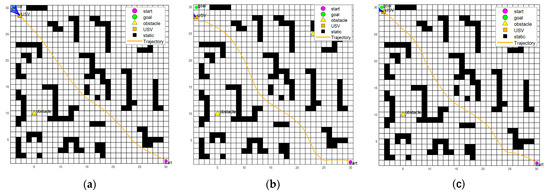
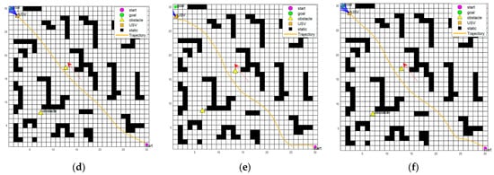
The comparison of the path planning results for DWA, the fuzzy improved DWA, and the fuzzy improved DWA with other membership functions is shown in Figure 13. These include comparisons of the DWA, fuzzy improved DWA, and fuzzy improved DWA with other membership functions in both static and dynamic–static mixed scenarios.
Figure 13.
Comparison of the DWA, fuzzy improved DWA, and fuzzy improved DWA with other membership functions in static and dynamic–static mixed scenarios. (a) DWA in static scenario; (b) Fuzzy improved DWA with other membership functions in static scenario; (c) Fuzzy improved DWA in static scenario; (d) DWA in dynamic–static mixed scenario; (e) Fuzzy improved DWA with other membership functions in dynamic–static mixed scenario; (f) Fuzzy improved DWA in dynamic–static mixed scenario.
The relevant comparative analysis is shown in Table 7.
Table 7.
Relevant comparison of the fuzzy improved DWA algorithm.
Based on the analysis of the above results, the following points can be summarized:
- The improved fuzzy DWA algorithm can maintain a safe distance from obstacles while keeping the original algorithm’s computation time and path length nearly unchanged.
- As time progresses and the surrounding environment changes, the weight coefficients are continuously adjusted, demonstrating strong adaptability in both static and dynamic–static mixed scenarios.
- In Figure 13b,e, it can be observed that when the USV passes the first dynamic obstacle, the unreasonable setting of the function causes the USV to take an overly safe route, resulting in significant time and path overhead. Additionally, when approaching the target point, due to the presence of static obstacles nearby and the influence of the function, the USV fails to reach the target point successfully. Furthermore, it can be observed that and play a key role in the entire path-planning process.
- Compared with other membership functions, the membership functions designed in this paper show advantages in shorter time, better safety, and greater stability.
5.2. Experimental Validation of the Fuzzy Improved DWA Algorithm Combined with COLREGS
To validate the fuzzy improved DWA algorithm combined with COLREGS, single-ship encounter scenarios and multi-target encounter scenarios with static obstacles were selected. The DWA, DWA combined with COLREGS, and the fuzzy improved DWA algorithm combined with COLREGS were compared. The single-ship encounter scenario and the multi-target encounter scenario with static obstacles are explained below.
5.2.1. Single-Ship Encounter Scenario
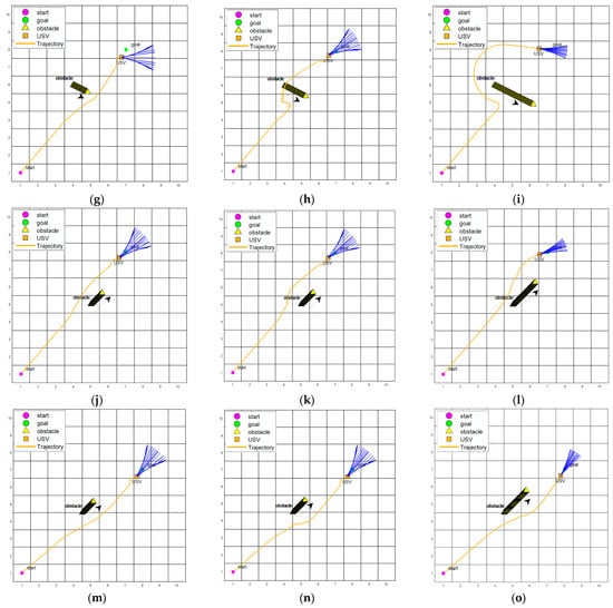
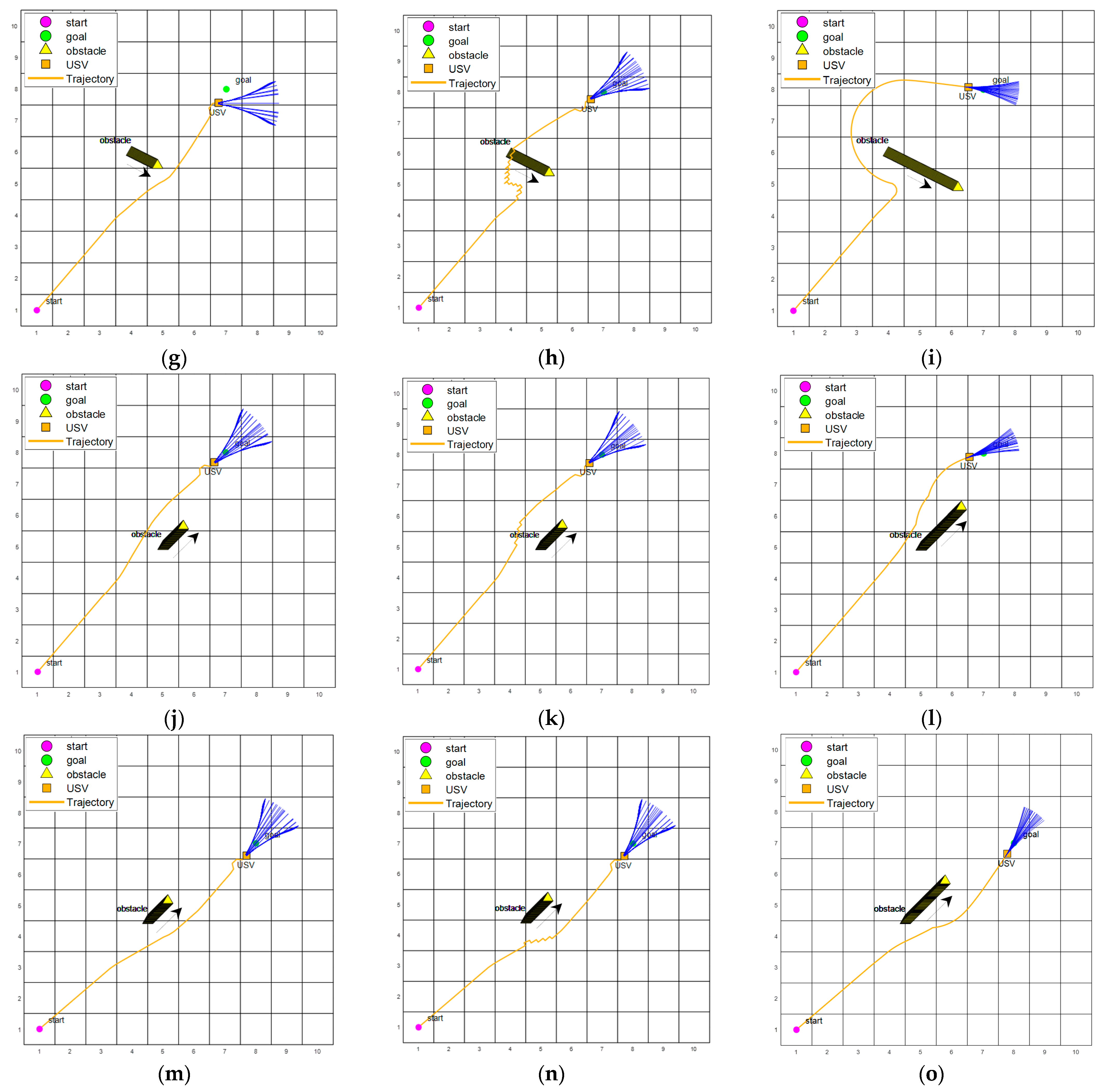
To validate the effectiveness of the proposed fuzzy improved DWA algorithm combined with COLREGS, a single-ship encounter scenario was set up with a grid size of . The bold black lines near the yellow triangles represent the movement trajectories of the obstacle vessels. The remaining map details are the same as those described in Section 5.1. The relevant parameter information was initialized, as shown in Table 5.
The comparison of the DWA, DWA combined with COLREGS, and the fuzzy improved DWA algorithm combined with COLREGS in the single-ship scenario is shown in Figure 14. The single-ship encounter scenario demonstrates the planning ability of the fuzzy improved DWA algorithm combined with COLREGS in five types of encounters: head-on, starboard crossing, port crossing, port overtaking, and starboard overtaking.
Figure 14.
Comparison of the DWA, DWA combined with COLREGS, and fuzzy improved DWA combined with COLREGS in five types of encounters. (a) DWA in head-on encounter scenario; (b) DWA combined with COLREGS in head-on encounter scenario; (c) Fuzzy improved DWA algorithm combined with COLREGS in head-on encounter scenarios; (d) DWA in starboard crossing scenario; (e) DWA combined with COLREGS in starboard crossing scenario; (f) Fuzzy improved DWA algorithm combined with COLREGS in starboard crossing scenario; (g) DWA in port crossing scenario; (h) DWA combined with COLREGS in port crossing scenario; (i) Fuzzy improved DWA algorithm combined with COLREGS in port crossing scenario; (j) DWA in port overtaking scenario; (k) DWA combined with COLREGS in port overtaking scenario; (l) Fuzzy improved DWA algorithm combined with COLREGS in port overtaking scenario; (m) DWA in starboard overtaking scenario; (n) DWA combined with COLREGS in starboard overtaking scenario; (o) Fuzzy improved DWA algorithm combined with COLREGS in starboard overtaking scenario.
The relevant comparative analysis is shown in Table 8.
Table 8.
Relevant comparison of the fuzzy improved DWA algorithm combined with COLREGS.
Based on the analysis of the simulation results of the single-ship encounter scenario for the three algorithms, the following points can be summarized:
- The DWA has the advantage of fast speed and produces relatively short paths, but it maintains a shorter distance from dynamic obstacles. When passing obstacles, the USV is usually at high speed, leading to lower safety.
- The DWA combined with COLREGS effectively constrains the obstacle avoidance direction of the USV and allows it to navigate using the safest possible path. The time consumption is not significantly increased compared with the DWA algorithm, but issues such as sudden changes in the heading angle and path oscillations during navigation are present.
- The fuzzy improved DWA algorithm combined with COLREGS effectively solves the problems of the DWA combined with COLREGS. By adding heading angle constraints and fuzzy rules, it ensures smooth paths while maintaining a safe distance, avoiding severe heading changes, and target inaccessibility issues. Although the time increases by an average of 24.7% compared with the DWA, the safety distance increases by an average of 66.1%, making the improved algorithm more advantageous in terms of safety and compliance.
5.2.2. Multi-Target Encounter Scenario with Static Obstacles
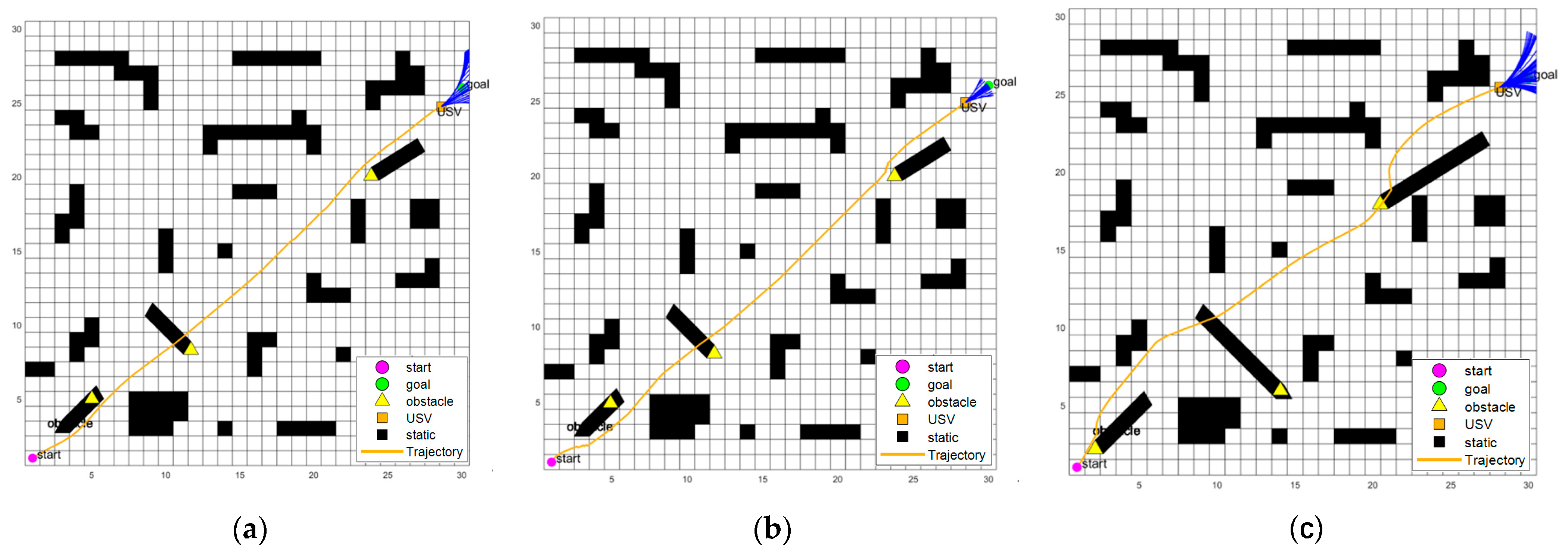
To validate the effectiveness of the proposed fuzzy improved DWA algorithm combined with COLREGS, a multi-target encounter scenario with static obstacles was set up, with a grid size of . The bold black lines near the yellow triangles represent the movement trajectories of the obstacle vessels. The remaining map details are the same as those described in Section 5.1. The relevant parameter information was initialized, as shown in Table 5.
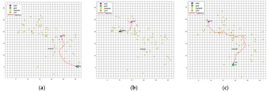
The comparison of the DWA, DWA combined with COLREGS, and the fuzzy improved DWA algorithm combined with COLREGS in the multi-target encounter scenario with static obstacles is shown in Figure 15.
Figure 15.
Comparison of the DWA, DWA combined with COLREGS, and fuzzy improved DWA combined with COLREGS in multi-target encounter scenarios with static obstacles. (a) DWA in multi-target encounter scenario with static obstacles; (b) DWA combined with COLREGS in multi-target encounter scenario with static obstacles; (c) Fuzzy improved DWA algorithm combined with COLREGS in multi-target encounter scenario with static obstacles.
The relevant comparative analysis is shown in Table 9.
Table 9.
Relevant comparison of the fuzzy improved DWA algorithm combined with COLREGS.
Based on the analysis of the simulation results for the multi-target encounter scenario with static obstacles using the three algorithms, the following points can be summarized:
- COLREGS is more effective for dynamic obstacle avoidance. In the multi-target encounter scenario with static obstacles, the USV can maintain a distance greater than 0.6 m from dynamic obstacles and greater than 0.2 m from static obstacles.
- Fuzzy rules are more effective for avoiding static obstacles, speed adjustment, and direction adjustment. In the multi-target encounter scenario with static obstacles, fuzzy rules can enforce a certain safety distance, ensuring that the USV safely navigates around static obstacles while maintaining as much distance as possible from dynamic obstacles, thereby improving the overall safety of the path planning.
5.3. Case Validation
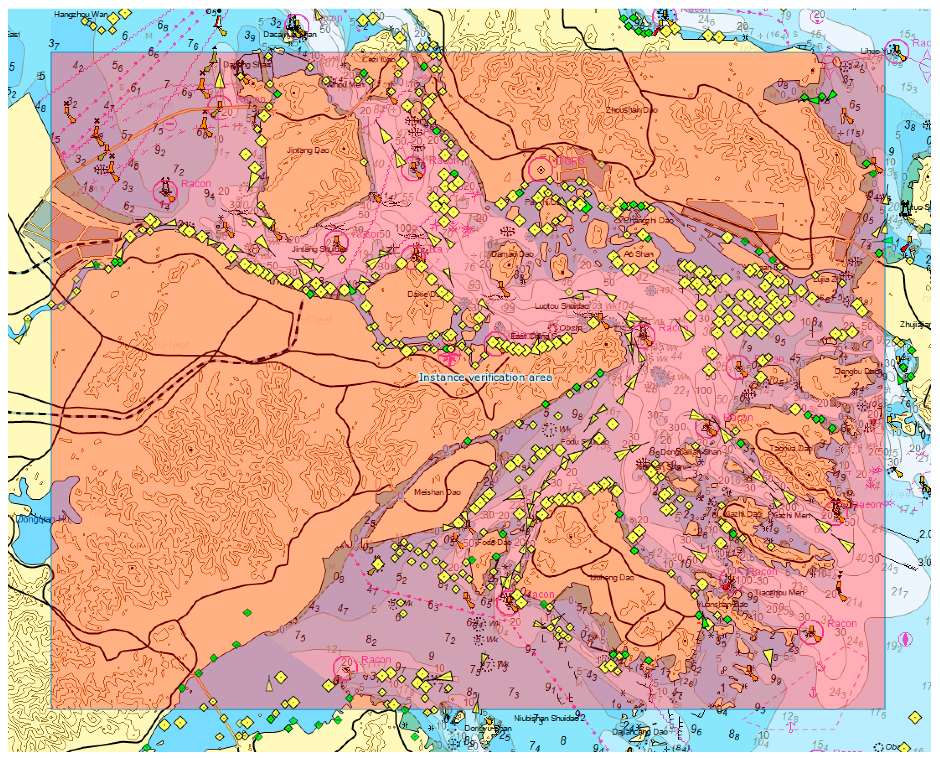
To validate the effectiveness of the fuzzy improved DWA algorithm combined with COLREGS using real-world data, actual vessel data from the Port of Ningbo–Zhoushan was used. The recommended shipping route was taken as the reference experimental route, and AIS data from vessels between 12:00 and 14:00 on 10 September 2019 was selected. The area of interest was between latitudes 29°38′ N to 30°6′ N and longitudes 121°40′ E to 122°21′ E.
The specific area is shown in the red region of Figure 16.
Figure 16.
Case validation area.
A case validation scenario was set up, converting the area from latitudes 29°38′ N to 30°6′ N and longitudes 121°40′ E to 122°21′ E into a sized grid. The magenta circle (start) represents the starting point, the green circle (goal) represents the target point, the orange square (USV) represents the position of our vessel, and the yellow square (obstacle) represents dynamic vessels.
The initialization parameters are shown in Table 10.
Table 10.
Initialize parameter settings.
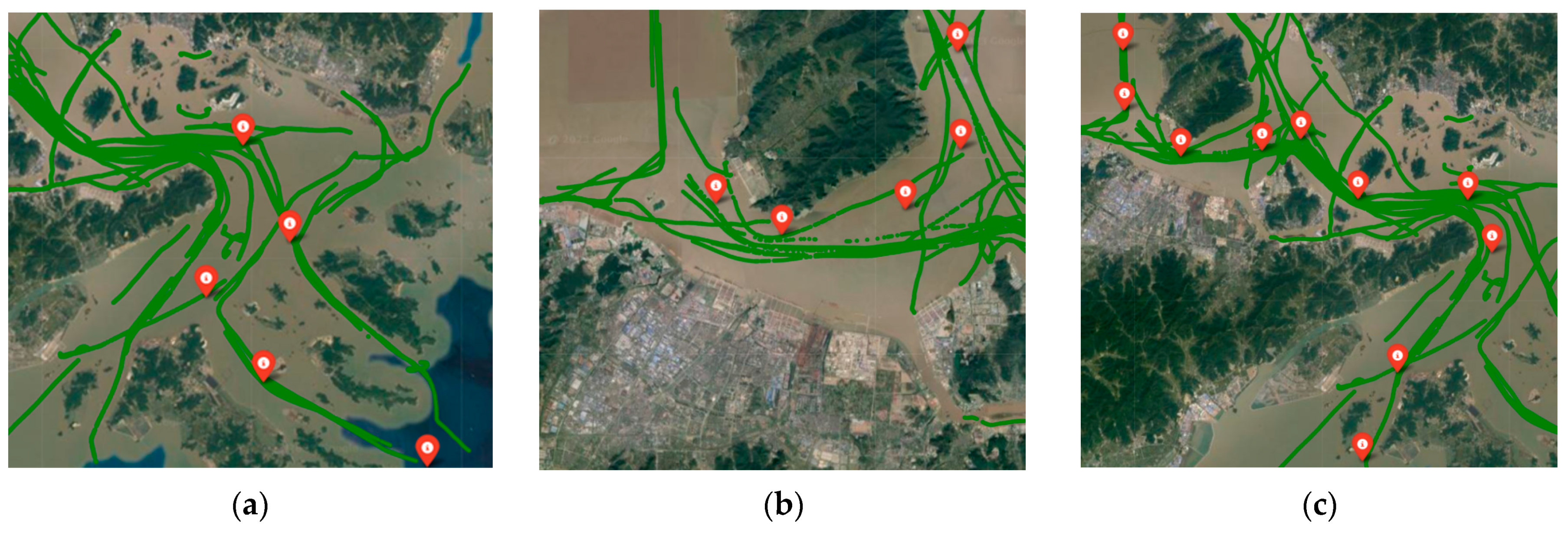
The following three routes were selected for validation.
Route 1: Starting from Yangxiaomao Island, passing through Qitouyang and Touyang Port, and finally reaching Tiaozhoumen. The path points’ latitudes and longitudes are: [29.92295° N, 122.160133° E], [29.8524833° N, 122.199717° E], [29.81275° N, 122.129533° E], [29.75075° N, 122.1779° E], [29.68905° N, 122.314814° E].
Route 2: Starting from Cezi Waterway, passing through Nanshan Cape and Jintang Waterway, and ending near Waiwan Cape. The path points’ latitudes and longitudes are: [30.03426667° N, 121.94106667° E], [29.9965° N, 121.94245° E], [29.98495° N, 121.90506667° E], [29.96321667° N, 121.86246667° E], [29.97533333° N, 121.83286667° E].
Route 3: Starting near the Jintang Bridge, passing through Waiwan Cape, Tuni Men Island, Maozuiba Cape, Changbing Cape, Yangxiaomao Island, Fodu Waterway, and Shuangyu Gate, and ending near Wenzhou Zhi. The path points’ latitudes and longitudes are: [30.0440167° N, 121.8051° E], [29.9952667° N, 122.806817° E], [29.9579° N, 122.859483° E], [29.96265° N, 121.935717° E], [29.97215° N, 121.972617° E], [29.9232° N, 121.025667° E], [29.9228333° N, 122.1286° E], [29.8800167° N, 122.15115° E], [29.7822333° N, 122.062717° E], [29.7101667° N, 122.029717° E].
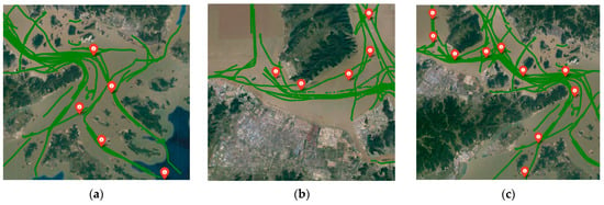
The green sections represent the visualization of vessel AIS data on Google tiles, while the red points indicate the marked path points.
The specific routes are shown in Figure 17.
Figure 17.
Guided routes. (a) Route 1; (b) Route 2; (c) Route 3.
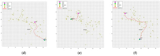
The comparison experiments between the fuzzy improved DWA algorithm combined with COLREGS and the DWA algorithm are shown in Figure 18.
Figure 18.
Comparison between the routes of the fuzzy improved DWA combined with COLREGS and the route of the DWA algorithm. (a) Route 1 for the fuzzy improved DWA algorithm combined with COLREGS; (b) Route 2 for the fuzzy improved DWA algorithm combined with COLREGS; (c) Route 3 for the fuzzy improved DWA algorithm combined with COLREGS; (d) Route 1 for the DWA algorithm; (e) Route 2 for the DWA algorithm; (f) Route 3 for the DWA algorithm.
The analysis will now focus solely on Route 1 generated by the fuzzy improved DWA algorithm combined with COLREGS.
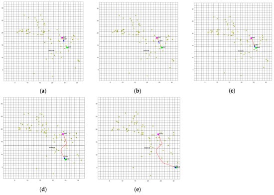
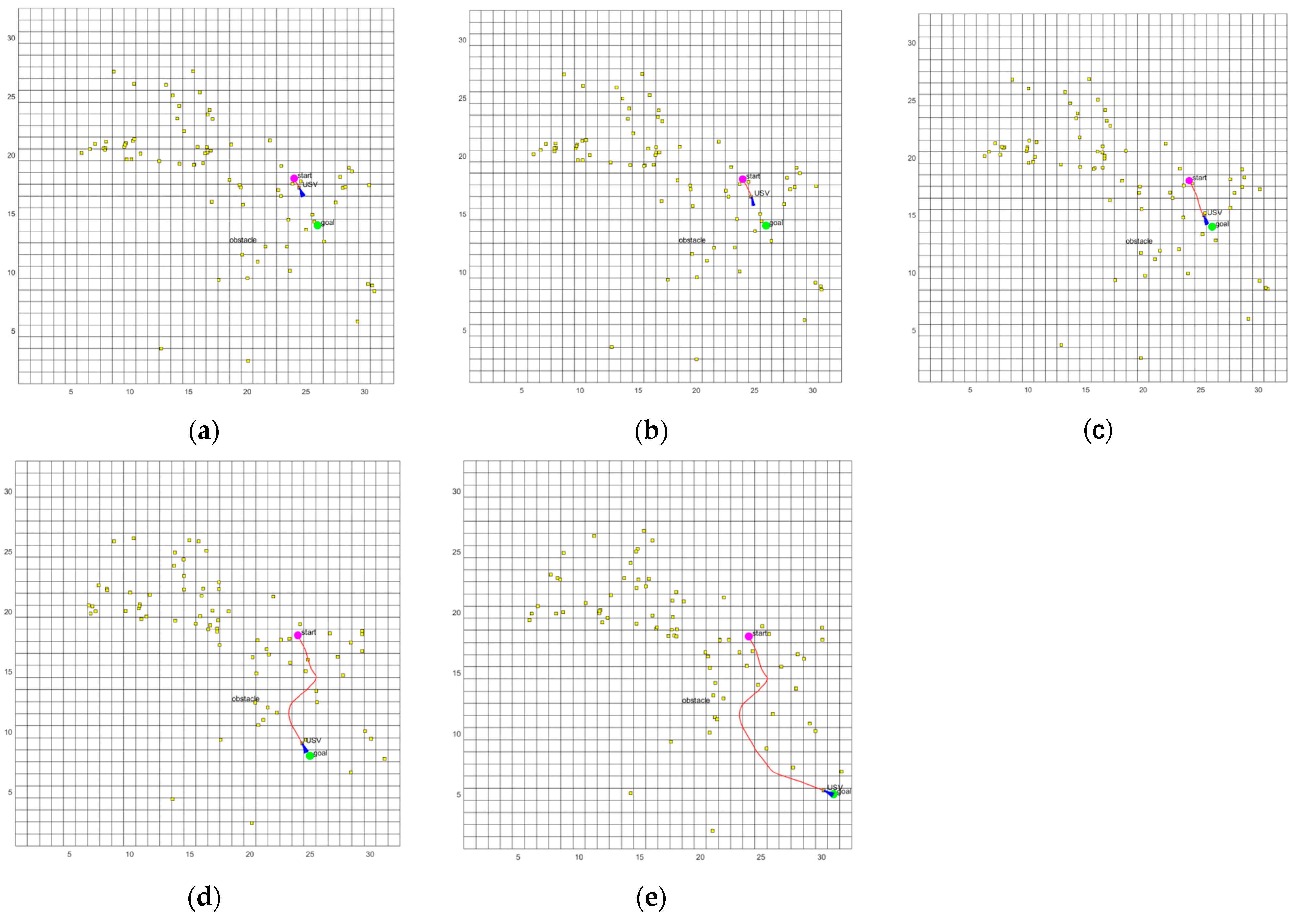
The obstacle avoidance process of Route 1 is shown in Figure 19.
Figure 19.
Obstacle avoidance process of route 1. (a) Detection of the first dynamic obstacle; (b) Detection of the second dynamic obstacle; (c) Detection of the third dynamic obstacle; (d) Detection of the fourth dynamic obstacle; (e) End.
The analysis is as follows:
- The USV begins its navigation on the right side of Xiaomao Island. Upon departure from the starting position, the first dynamic obstacle is detected. However, since the obstacle is moving to the right and does not pose a safety threat to the USV, and because there are multiple dynamic obstacles in the vicinity, the USV quickly passes through the middle of the obstacles and proceeds toward the first target point.
- Upon detecting the second dynamic obstacle, a head-on situation with the obstacle is formed. Therefore, the USV turns to the right to avoid the obstacle and heads toward the second target point.
- After turning, the USV detects the third dynamic obstacle, but since the direction of this obstacle does not affect the USV, the USV bypasses it and proceeds to the third target point.
- While advancing to the fourth target point, the USV detects the fourth dynamic obstacle, forming a starboard overtaking situation. The USV bypasses the obstacle on its right side and continues toward the final destination.
- Throughout the entire voyage, the USV maintained a safe distance from obstacles, with moderate speed and a smooth trajectory.
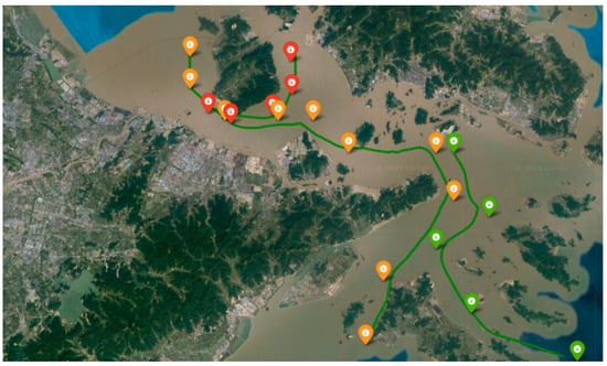
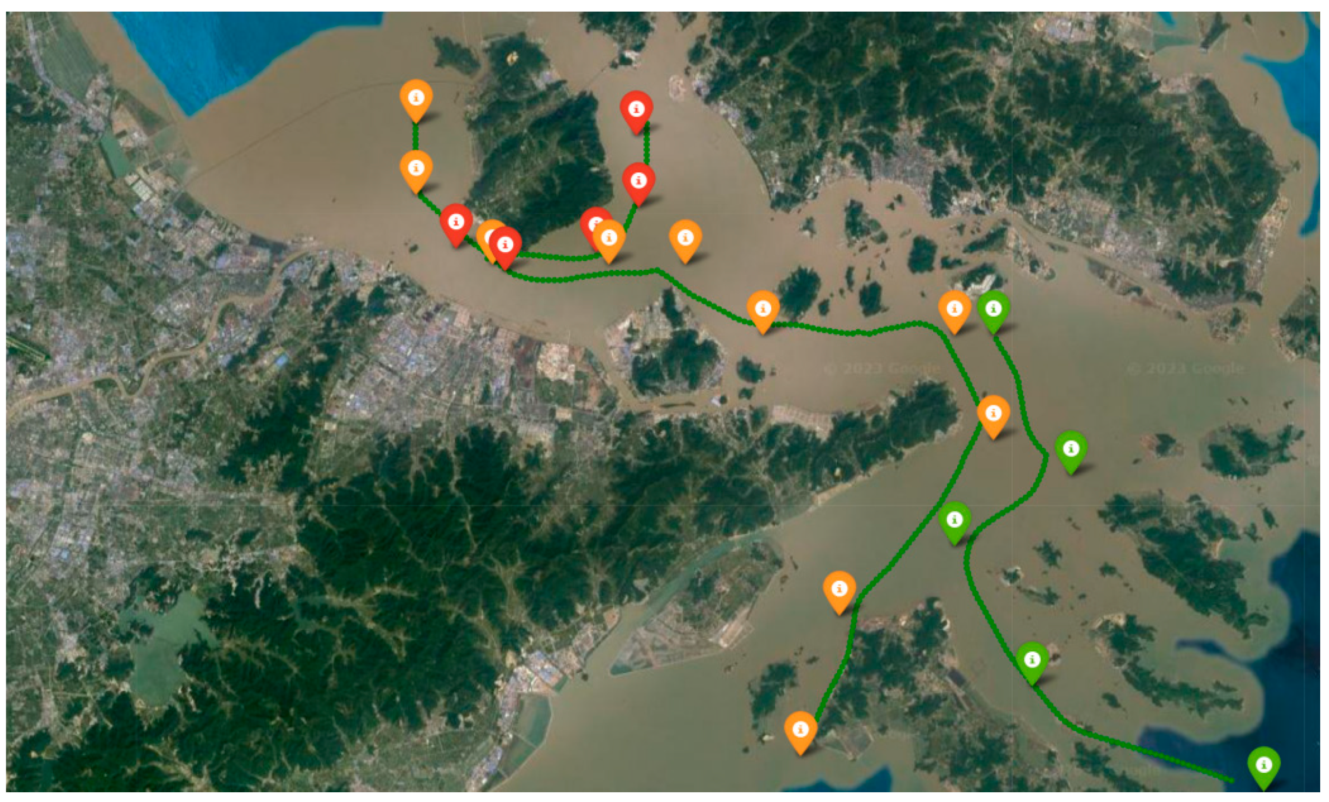
To more intuitively observe the correspondence between the recommended routes and the planned routes in this study, the results are displayed using Google tiles. The specific results are shown in Figure 20. The green marked points are route 1 waypoints, the red marked points are route 2 waypoints, the orange marked points are route 3 waypoints, and the green visualized tracks correspond to the three planned routes respectively.
Figure 20.
Route visualization results.
Results and error analysis: Green markers indicate the path points for Route 1, red markers represent the path points for Route 2, and orange markers denote the path points for Route 3. The green visualized trajectories correspond to the three planned routes. The results show that the planned paths generally follow the designated path points as expected. However, there are some noticeable errors in certain areas, such as individual route points being spaced further apart than anticipated or parts of these trajectory data shifting onto islands. The main reasons for the aforementioned issues are as follows:
- During data conversion, different decimal places were retained (with 1 degree of latitude or longitude corresponding to approximately 111 km). For example, when converting path point latitude and longitude data to the grid coordinate system, a rounding operation was performed. When converting dynamic vessel data to the coordinate system, three significant digits were retained. When displaying trajectory data on the map, eight significant digits were preserved.
- When determining whether a route point has been reached, an acceptable radius is set. Therefore, in path planning, reaching the defined area is considered sufficient to be deemed as having arrived without requiring the exact passage through the path point.
The case validation comparative analysis is shown in Table 11.
Table 11.
Case validation comparative analysis.
Based on the analysis of the above results, the following points can be summarized:
- In terms of the number of nodes, there is little change between the algorithm before and after the improvement. However, in terms of path planning length, the improved algorithm shows an increase of approximately 2.01% compared with the original algorithm.
- In terms of rule handling, the original algorithm exhibited instances of non-compliant detours in Routes 1 and 3. The improved algorithm demonstrates better rule compliance in open waters, allowing the USV to navigate obstacles in the predetermined direction.
- Regarding navigation safety, the improved algorithm increased the safety distance by an average of 15.33% compared with the original algorithm, making the improved algorithm more advantageous in terms of safety.
- In terms of stability, the original algorithm encountered temporary obstacle avoidance failures at coordinates on Route 1 and on Route 2. The improved algorithm did not encounter this issue, demonstrating better overall stability in path planning.
Therefore, in conclusion, the proposed fuzzy improved DWA algorithm combined with COLREGS demonstrates strong adaptability to real-time AIS data from continuous vessel traffic. The USV can plan its route according to the established rules and flexibly switch between regular obstacle avoidance and rule-based obstacle avoidance when handling different encounter scenarios. It also offers advantages in terms of both safety and stability.
6. Conclusions
In this paper, we propose a fuzzy improved DWA algorithm combined with COLREGS for the local dynamic path planning of USVs. First, the USV motion model and traffic constraints are analyzed. Then, the traditional DWA algorithm is optimized by extending an additional target point attraction sub-function to the original evaluation function, allowing the USV to approach the target point more safely and quickly during navigation. Next, fuzzy logic is integrated with the improved DWA algorithm, providing robust dynamic path planning for USVs in various water environments such as narrow channels, reef areas, and open waters. Finally, COLREGS is introduced to design a fuzzy improved DWA algorithm that complies with COLREGS, ensuring the USV adheres to these regulations during navigation. The proposed algorithm is validated through algorithm implementation and analysis, comparing the fuzzy improved DWA algorithm and the fuzzy improved DWA algorithm combined with COLREGS. Both virtual scenarios and case validations were designed to evaluate the algorithm’s performance, demonstrating that it complies with COLREGS and exhibits significant advantages in terms of safety and stability.
However, the proposed algorithm overlooks the impact of environmental factors such as ocean currents, which introduces certain limitations. In future research, we will further consider the influence of environmental factors and conduct real-world tests to ensure that the proposed method can operate safely and stably in various real-world environments.
Author Contributions
Methodology, J.P., X.Z. and Q.Z.; software, X.Z. and Q.Z.; validation, J.P., X.Z. and Q.Z.; writing—original draft preparation, X.Z.; writing—review and editing, X.Z.; supervision, J.P. All authors have read and agreed to the published version of the manuscript.
Funding
This research was funded by the Ministry of Science and Technology—National Key Research and Development Plan (Grant number Z20228010) and the Key project of the National Natural Science Foundation (Grant number Z20238114).
Institutional Review Board Statement
Not applicable.
Informed Consent Statement
Not applicable.
Data Availability Statement
The original contributions presented in the study are included in the article; further inquiries can be directed to the corresponding authors.
Conflicts of Interest
The authors declare no conflicts of interest.
References
- Fan, Y.; Sun, Z.; Wang, G. A Novel Intelligent Collision Avoidance Algorithm Based on Deep Reinforcement Learning Approach for USV. Ocean Eng. 2023, 287, 115649. [Google Scholar] [CrossRef] [Scilit]
- Sun, Z.; Fan, Y.; Wang, G. An Intelligent Algorithm for USVs Collision Avoidance Based on Deep Reinforcement Learning Approach with Navigation Characteristics. J. Mar. Sci. Eng. 2023, 11, 812. [Google Scholar] [CrossRef] [Scilit]
- Er, M.J.; Ma, C.; Liu, T.; Gong, H. Intelligent Motion Control of Unmanned Surface Vehicles: A Critical Review. Ocean Eng. 2023, 280, 114562. [Google Scholar] [CrossRef] [Scilit]
- Yan, R.; Pang, S.; Sun, H.; Pang, Y. Development and Missions of Unmanned Surface Vehicle. J. Mar. Sci. Appl. 2010, 9, 451–457. [Google Scholar] [CrossRef] [Scilit]
- Jorge, V.A.M.; Granada, R.; Maidana, R.G.; Jurak, D.A.; Heck, G.; Negreiros, A.P.F.; Dos Santos, D.H.; Gonçalves, L.M.G.; Amory, A.M. A Survey on Unmanned Surface Vehicles for Disaster Robotics: Main Challenges and Directions. Sensors 2019, 19, 702. [Google Scholar] [CrossRef] [Scilit] [PubMed]
- Dong, Z.; Liu, J.; Li, C.; Li, S. Classification, Design, and Challenges of Unmanned Ships in Marine Transportation. In Proceedings of the 2021 6th International Conference on Transportation Information and Safety (ICTIS), Wuhan, China, 22–24 October 2021; pp. 985–992. [Google Scholar]
- Jin, X.; Er, M.J. Cooperative Path Planning with Priority Target Assignment and Collision Avoidance Guidance for Rescue Unmanned Surface Vehicles in a Complex Ocean Environment. Adv. Eng. Inf. 2022, 52, 101517. [Google Scholar] [CrossRef] [Scilit]
- Liu, X.; Li, Y.; Zhang, J.; Zheng, J.; Yang, C. Self-Adaptive Dynamic Obstacle Avoidance and Path Planning for USV under Complex Maritime Environment. IEEE Access 2019, 7, 114945–114954. [Google Scholar] [CrossRef] [Scilit]
- Liu, Y.; Peng, Y.; Wang, M.; Xie, J.; Zhou, R. Multi-USV System Cooperative Underwater Target Search Based on Reinforcement Learning and Probability Map. Math. Probl. Eng. 2020, 2020, 7842768. [Google Scholar] [CrossRef] [Scilit]
- Xiaofei, Y.; Yilun, S.; Wei, L.; Hui, Y.; Weibo, Z.; Zhengrong, X. Global Path Planning Algorithm Based on Double DQN for Multi-Tasks Amphibious Unmanned Surface Vehicle. Ocean Eng. 2022, 266, 112809. [Google Scholar] [CrossRef] [Scilit]
- Long, Y.; Liu, S.; Qiu, D.; Li, C.; Guo, X.; Shi, B.; AbouOmar, M.S. Local Path Planning with Multiple Constraints for USV Based on Improved Bacterial Foraging Optimization Algorithm. J. Mar. Sci. Eng. 2023, 11, 489. [Google Scholar] [CrossRef] [Scilit]
- Marin-Plaza, P.; Hussein, A.; Martin, D.; Escalera, A.D.L. Global and Local Path Planning Study in a ROS-Based Research Platform for Autonomous Vehicles. J. Adv. Transp. 2018, 2018, 6392697. [Google Scholar] [CrossRef] [Scilit]
- Warren, C.W. Global Path Planning Using Artificial Potential Fields. In Proceedings of the 1989 International Conference on Robotics and Automation, Scottsdale, AZ, USA, 14–19 May 1989; pp. 316–321. [Google Scholar]
- Kobayashi, M.; Motoi, N. Local Path Planning: Dynamic Window Approach with Virtual Manipulators Considering Dynamic Obstacles. IEEE Access 2022, 10, 17018–17029. [Google Scholar] [CrossRef] [Scilit]
- Khatib, O. Real-Time Obstacle Avoidance for Manipulators and Mobile Robots. In Proceedings of the 1985 IEEE International Conference on Robotics and Automation, St. Louis, MO, USA, 25–28 March 1985; Volume 2, pp. 500–505. [Google Scholar]
- Zhu, Q.; Yan, Y.; Xing, Z. Robot Path Planning Based on Artificial Potential Field Approach with Simulated Annealing. In Proceedings of the Sixth International Conference on Intelligent Systems Design and Applications, Jinan, China, 16–18 October 2006; Volume 2, pp. 622–627. [Google Scholar]
- Wang, P.; Gao, S.; Li, L.; Sun, B.; Cheng, S. Obstacle Avoidance Path Planning Design for Autonomous Driving Vehicles Based on an Improved Artificial Potential Field Algorithm. Energies 2019, 12, 2342. [Google Scholar] [CrossRef] [Scilit]
- Borenstein, J.; Koren, Y. The Vector Field Histogram-Fast Obstacle Avoidance for Mobile Robots. IEEE Trans. Robot. Autom. 1991, 7, 278–288. [Google Scholar] [CrossRef] [Scilit]
- Borenstein, J.; Koren, Y. Real-Time Obstacle Avoidance for Fast Mobile Robots. IEEE Trans. Syst. Man Cybern. 1989, 19, 1179–1187. [Google Scholar] [CrossRef] [Scilit]
- Ulrich, I.; Borenstein, J. VFH+: Reliable Obstacle Avoidance for Fast Mobile Robots. In Proceedings of the 1998 IEEE International Conference on Robotics and Automation (Cat. No. 98CH36146), Leuven, Belgium, 20 May 1998; Volume 2, pp. 1572–1577. [Google Scholar]
- Ulrich, I.; Borenstein, J. VFH/Sup */: Local Obstacle Avoidance with Look-Ahead Verification. In Proceedings of the Proceedings 2000 ICRA, Millennium Conference, IEEE International Conference on Robotics and Automation, Symposia Proceedings (Cat. No.00CH37065), San Francisco, CA, USA, 24–28 April 2000; Volume 3, pp. 2505–2511. [Google Scholar]
- Fox, D.; Burgard, W.; Thrun, S. The Dynamic Window Approach to Collision Avoidance. IEEE Robot. Autom. Mag. 1997, 4, 23–33. [Google Scholar] [CrossRef] [Scilit]
- Zhang, F.; Li, N.; Xue, T.; Zhu, Y.; Yuan, R.; Fu, Y. An Improved Dynamic Window Approach Integrated Global Path Planning. In Proceedings of the 2019 IEEE International Conference on Robotics and Biomimetics (ROBIO), Dali, China, 6–8 December 2019; pp. 2873–2878. [Google Scholar]
- Li, X.; Liu, F.; Liu, J.; Liang, S. Obstacle Avoidance for Mobile Robot Based on Improved Dynamic Window Approach. Turk. J. Electr. Eng. Comput. Sci. 2017, 25, 666–676. [Google Scholar] [CrossRef] [Scilit]
- Abdalla, T.Y.; Abed, A.A.; Ahmed, A.A. Mobile Robot Navigation Using PSO-Optimized Fuzzy Artificial Potential Field with Fuzzy Control. J. Intell. Fuzzy Syst. 2017, 32, 3893–3908. [Google Scholar] [CrossRef] [Scilit]
- Babinec, A.; Duchoň, F.; Dekan, M.; Pásztó, P.; Kelemen, M. VFH*TDT (VFH* with Time Dependent Tree): A New Laser Rangefinder Based Obstacle Avoidance Method Designed for Environment with Non-Static Obstacles. Robot. Auton. Syst. 2014, 62, 1098–1115. [Google Scholar] [CrossRef] [Scilit]
- Dobrevski, M.; Skocaj, D. Adaptive Dynamic Window Approach for Local Navigation. In Proceedings of the 2020 IEEE/RSJ International Conference on Intelligent Robots and Systems (IROS), Las Vegas, NV, USA, 24 October 2020; pp. 6930–6936. [Google Scholar]
- Zhang, J.H.; Feng, Q.; Zhao, A.D.; He, W.; Hao, X. Local Path Planning of Mobile Robot Based on Self-Adaptive Dynamic Window Approach. J. Phys. Conf. Ser. 2021, 1905, 12019. [Google Scholar] [CrossRef] [Scilit]
- Li, J.; Wan, L.; Huang, Z.; Chen, Y.; Tang, H. Hybrid Path Planning Strategy Based on Improved Particle Swarm Optimisation Algorithm Combined with DWA for Unmanned Surface Vehicles. J. Mar. Sci. Eng. 2024, 12, 1268. [Google Scholar] [CrossRef] [Scilit]
- Huang, Y.; Zhao, S.; Zhao, S. Ship Trajectory Planning and Optimization via Ensemble Hybrid A* and Multi-Target Point Artificial Potential Field Model. J. Mar. Sci. Eng. 2024, 12, 1372. [Google Scholar] [CrossRef] [Scilit]
- Li, H.; Wang, X.; Wu, T.; Ni, S. A COLREGs-Compliant Ship Collision Avoidance Decision-Making Support Scheme Based on Improved APF and NMPC. J. Mar. Sci. Eng. 2023, 11, 1408. [Google Scholar] [CrossRef] [Scilit]
- Zhao, X.; Zhao, Q.; Peng, J. Research on Improved Dynamic Window Approach Based on Fuzzy Logic for Adaptive Obstacle Avoidance Control in Unmanned Surface Vehicles. In Proceedings of the Fifth International Conference on Signal Processing and Computer Science (SPCS 2024). 2024, unpublished work.
- Fossen, T.I. Marine Control Systems: Guidance, Navigation and Control of Ships, Rigs and Underwater Vehicles; Marine Cybernetics: Trondheim, Norway, 2002; ISBN 978-82-92356-00-5. [Google Scholar]
- Xu, J.-X.; Xu, J. A New Fuzzy Logic Learning Control Scheme for Repetitive Trajectory Tracking Problems. Fuzzy Sets Syst. 2003, 133, 57–75. [Google Scholar] [CrossRef] [Scilit]
- De Andrés-Sánchez, J. A Systematic Review of the Interactions of Fuzzy Set Theory and Option Pricing. Expert Syst. Appl. 2023, 223, 119868. [Google Scholar] [CrossRef] [Scilit]
- Mendes, J.; Maia, R.; Araújo, R.; Souza, F.A.A. Self-Evolving Fuzzy Controller Composed of Univariate Fuzzy Control Rules. Appl. Sci. 2020, 10, 5836. [Google Scholar] [CrossRef] [Scilit]
- Elmas, C.; Deperlioglu, O.; Sayan, H.H. Adaptive Fuzzy Logic Controller for DC–DC Converters. Expert Syst. Appl. 2009, 36, 1540–1548. [Google Scholar] [CrossRef] [Scilit]

Disclaimer/Publisher’s Note: The statements, opinions and data contained in all publications are solely those of the individual author(s) and contributor(s) and not of MDPI and/or the editor(s). MDPI and/or the editor(s) disclaim responsibility for any injury to people or property resulting from any ideas, methods, instructions or products referred to in the content. |
© 2024 by the authors. Licensee MDPI, Basel, Switzerland. This article is an open access article distributed under the terms and conditions of the Creative Commons Attribution (CC BY) license (https://creativecommons.org/licenses/by/4.0/).