


Highlights
What are the main findings?
- The proposed direct lift/side-force architecture improves vertical and lateral tracking while keeping angle of attack, bank angle, and sideslip close to their landing trim values.
- The predefined-time observer and flap anti-saturation mechanism improve disturbance rejection and retain actuator-feasible landing performance under deck motion, airwake, gusts, and randomized initial errors.
What are the implications of the main findings?
- Direct-force effectors can correct glide-slope and lineup errors with less reliance on attitude-mediated motion, supporting safer touchdown geometry and more consistent arresting-hook engagement.
- Integrating prescribed transient timing with saturation-aware compensation offers a practical approach to robust carrier-landing control when rapid disturbance rejection is required within limited control authority.
Abstract
Carrier-based fixed-wing UAV landing is challenged by deck motion, carrier airwake, gust disturbances, strong trajectory–attitude coupling, and actuator constraints. To address these issues, this paper proposes a Predefined-Time Direct Lift/Side-Force-Integrated Approach Landing (PTDIAL) method. An integrated direct-force architecture is constructed using the trailing-edge flap for direct lift and the spoiler for direct side force, thereby reducing the dependence of trajectory correction on angle-of-attack- and bank-angle/sideslip-mediated regulation. A preview-based reference glide slope is generated from the predicted Ideal Touch Point (ITP) sequence to improve the response to deck motion. Predefined-time control laws are developed for the cascaded position, trajectory, attitude, angular rate, and velocity loops, with prescribed-performance constraints imposed on the attitude response. A predefined-time disturbance observer is introduced to estimate the lumped aerodynamic disturbances, while an auxiliary anti-saturation mechanism compensates for the effect of trailing-edge flap saturation. Lyapunov analysis establishes the practical predefined-time stability of the closed-loop system under bounded disturbances and actuator constraints. Various simulations demonstrate that the proposed architecture improves lateral and vertical tracking while preserving the UAV attitude, and Monte Carlo simulations further confirm the robustness of PTDIAL.
1. Introduction
Carrier-based fixed-wing unmanned aerial vehicles (UAVs) have attracted increasing attention because of their potential applications in maritime surveillance, reconnaissance, and autonomous strike missions [1]. For such UAVs, automatic carrier landing is one of the most demanding flight tasks, since the vehicle must approach a limited landing area with high accuracy within a short terminal phase [2,3]. During final approach, small deviations in the lateral or vertical position may lead to large touchdown errors near the Ideal Touch Point (ITP) [4]. Therefore, an effective landing controller should ensure fast error convergence, accurate attitude regulation, and reliable disturbance rejection.
The carrier-landing environment is highly challenging due to the combined effects of carrier airwake, deck motion, and atmospheric gusts [5,6]. The carrier airwake introduces complex wind disturbances around the stern, while deck motion changes the relative position of the ITP and directly affects the desired approach path. In addition, gust disturbances may cause abrupt variations in the flight-path angle, heading angle, and angular rate dynamics [5,6]. These factors make the UAV landing problem a strongly coupled tracking-control problem, where the position loop, trajectory loop, attitude loop, and velocity loop must be coordinated under time-varying disturbances.
In landing systems, deck motion information is commonly predicted on the carrier side and transmitted to the UAV for guidance command correction [7]. Typical short-term prediction methods include autoregressive (AR) models [2,8,9], recursive least squares (RLS) [6], and long short-term memory (LSTM) networks [10]. Owing to the inertia characteristic of ship motion, these methods usually provide comparable accuracy over a short prediction horizon. By embedding the predicted ITP motion into the guidance law [2,3,6], the tracking delay caused by deck motion can be alleviated. However, if the predicted ITP sequence is directly used as a moving reference, rapid changes in the deck motion trend may introduce aggressive guidance commands and induce undesirable fluctuations in the trajectory and attitude responses. Therefore, the predicted sequence should be integrated into the guidance law in a smooth and coordinated manner.
In contrast to reference variations induced by deck motion, carrier airwake and gust disturbances directly affect the UAV dynamics through aerodynamic force and moment perturbations [3,5,6,8]. Existing studies usually address these disturbances under nonlinear dynamic inversion (NDI) or backstepping frameworks [2,6,11,12], where robust control techniques, such as sliding-mode control [2,5,13,14,15,16], are introduced to enhance disturbance rejection. Disturbance observers are further implemented in many designs to provide feedforward compensation, thereby reducing the need for overly conservative robust gains [2,5,8,17,18]. However, carrier airwake and especially gust disturbances are unsteady, stochastic, and rapidly varying, which imposes stricter requirements on the transient tracking accuracy and phase response of the disturbance observer.
Direct force control provides an effective way to reduce the coupling between trajectory regulation and attitude maneuvering for aircraft [19,20]. Instead of relying only on pitch attitude to reshape the flight path, direct-force effectors can generate incremental lift more directly, thereby improving response bandwidth and reducing controller workload [12]. This idea has been validated in practical carrier-landing applications through the MAGIC CARPET program [4], where integrated direct lift control and delta flight-path command were implemented on carrier-based aircraft to simplify glide-slope correction and improve touchdown consistency.
However, existing direct-force landing studies mainly focus on the longitudinal channel, especially direct lift control [2,5,12,21]. The lateral channel is still commonly handled through bank-angle/yaw-angle and sideslip-mediated dynamics. In the ATARI project [22], the delta-command concept was extended to the lateral direction to make lineup correction more intuitive, but the lateral motion was still produced mainly through conventional control surfaces and attitude-coupled dynamics. Nevertheless, the aircraft attitude itself must also be carefully maintained for touchdown geometry, arresting-hook engagement, and impact load reduction. Therefore, introducing a direct side-force channel is meaningful for carrier-based UAV landing.
From the convergence perspective, conventional asymptotic control can guarantee stability only over an infinite time horizon, which is not fully consistent with the strict time window of carrier landing [23,24]. Finite-time control improves the transient response by driving the tracking error to zero within a finite interval, but the settling time usually depends on the initial condition [13,25]. Fixed-time control removes this dependence by providing a uniform upper bound of the settling time, yet this bound is often implicit or conservative and cannot be directly adjusted according to the landing task [3,26]. Predefined-time control further addresses this limitation by allowing the convergence time to be specified in advance, making it more suitable for terminal approach problems with clear time requirements [2,5,27,28,29]. The same property is also desirable for disturbance observers [2,5,28,29], since accurate feedforward compensation must be established rapidly when airwake or gust disturbances enter the UAV dynamics. Recent learning-based studies have also investigated flexible constraint handling and adjustable convergence behavior [30,31]. However, enforcing fast convergence within a predefined time interval may lead to aggressive transient commands, which makes actuator constraints and anti-saturation design [14,32] an important issue in practical landing control.
To address the above issues, this paper develops a predefined-time integrated direct lift/side-force landing-control scheme for carrier-based fixed-wing UAVs. The main contributions are summarized as follows:
- 1.
- An integrated direct lift/side-force control architecture is developed for carrier landing. Existing direct-force landing studies mainly introduce a longitudinal direct-lift channel, while lateral correction is still commonly achieved through bank-angle- and sideslip-mediated motion. In contrast, the proposed architecture employs the trailing-edge flap and a differential-spoiler-based side-force channel for vertical and lateral trajectory correction, respectively, reducing reliance on attitude-mediated motion.
- 2.
- A unified practical predefined-time control framework is established for the cascaded position, trajectory, attitude, angular-rate, and velocity loops. In contrast to asymptotic and finite-time methods, the proposed design allows an upper bound on the convergence time to be specified in advance. Prescribed-performance constraints and predefined-time disturbance observation are incorporated into the same framework to regulate the attitude transient and compensate for the lumped disturbances.
- 3.
- An ITP-preview guidance strategy and a trailing-edge-flap anti-saturation mechanism are incorporated. The predicted ITP sequence is smoothly integrated into the guidance law, while the anti-saturation mechanism compensates for flap saturation and mitigates its coupled influence on the longitudinal channel.
The remainder of this paper is organized as follows. Section 2 formulates the carrier-based UAV landing problem and defines the control objectives. Section 3 introduces the theoretical tools used for controller, observer, and anti-saturation design. Section 4 presents the proposed landing control scheme. Section 5 analyzes the closed-loop stability. Section 6 validates the proposed method through simulation studies. Section 7 concludes this paper.
2. Problem Formulation
This section formulates the carrier-landing problem for a fixed-wing UAV under deck motion and wind disturbances.
2.1. UAV Model
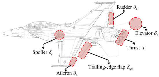
The inertial frame and the body-fixed frame are considered. The body-fixed frame is attached to the UAV, with its origin at the center of mass. The -axis points forward, the -axis points to the right wing, and the -axis points downward. The UAV configuration and the adopted control surfaces are illustrated in Figure 1.
Figure 1.
UAV configuration and control surfaces.
The high-fidelity simulation is based on the nonlinear six-degree-of-freedom (six-DOF) fixed-wing UAV model [33,34], whose main equations are summarized in Appendix A. For controller synthesis, the nonlinear dynamics are reorganized into a cascade affine form. The state variables are grouped as , , , and , where y and z denote the lateral and vertical positions, is the heading angle, is the flight-path angle, is the bank angle, is the angle of attack, is the sideslip angle, and p, q, and r are the roll rate, pitch rate, and yaw rate, respectively.
The control-oriented affine model is written as
where V is the velocity, T is the thrust command, is the compact state vector, and are the control inputs, , , , and are known nonlinear functions derived from the six-DOF model, and , , and denote lumped disturbances in the trajectory, angular rate, and velocity loops, respectively.
Assumption 1
([33]). Let collect the six lumped-disturbance channels associated with carrier airwake, gusts, and unmodeled aerodynamic effects. In addition to having finite amplitudes, these disturbances are assumed to vary at finite rates. Specifically, each , , is continuously differentiable during the landing interval, and there exist constants and such that and throughout that interval.
Assumption 2.
The input gain matrices or scalars used in the cascade loops, including , , , , and , are nonsingular or bounded away from zero within the considered landing envelope.
In the position loop, is regarded as the virtual control input for regulating . In the trajectory loop, the direct-force input is selected as , where denotes the differential spoiler deflection, and denotes the trailing-edge flap deflection. This spoiler-based direct side-force channel follows the DSFC concept in Cao et al. [34], where spoiler deflection is used to generate lateral force while reducing the dependence on bank-angle and sideslip motion. The attitude loop treats as the virtual control input for . The angular rate loop generates the conventional control-surface commands , where , , and denote the aileron, elevator, and rudder deflections, respectively. The velocity loop is independently regulated by thrust T. With the direct-force channels incorporated into the trajectory loop, the direct lift/side-force control architecture is formed.
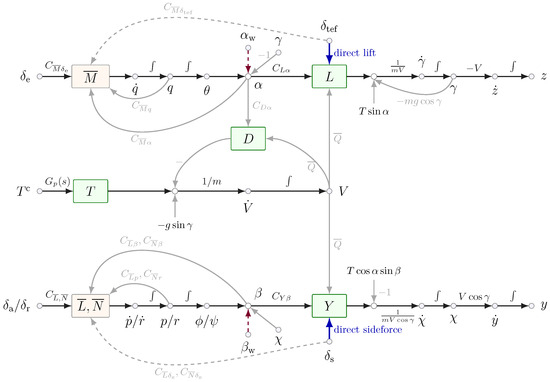
Figure 2 further illustrates the control signal flow of this architecture. To facilitate interpretation of the schematic, , , and denote the roll, pitch, and yaw Euler angles, respectively; represents the engine dynamics; is the dynamic pressure; and coefficients of the form denote the corresponding aerodynamic stability or control derivatives. The terms and represent the wind-induced equivalent angle-of-attack and sideslip perturbations, while arrows marked by ∫ indicate time integration along the corresponding dynamic paths. The remaining state, control, force, and moment symbols are defined above and summarized in Table A1, with the detailed aerodynamic and kinematic relations provided in Appendix A. The direct-force paths provide additional force-generation channels for trajectory correction, so that vertical and lateral position errors can be reduced with less reliance on angle-of-attack- and bank-angle/sideslip-mediated correction. In the conventional longitudinal path, vertical correction is transmitted through
Figure 2.
Control signal flow of the integrated direct lift/side-force architecture.
By contrast, the direct-lift path can be represented as
Thus, the trailing-edge flap can rapidly increase or decrease aerodynamic lift while keeping the angle-of-attack nearly unchanged, which bypasses the elevator-induced non-minimum-phase response, broadens the trajectory response bandwidth, and partially decouples trajectory motion from attitude motion. Similarly, the lateral channel is shortened from the conventional attitude-coupled path
to the direct side-force path
Remark 1.
For clarity, the conventional lateral path in Figure 2 and Equation (4) is represented by the sideslip-induced side-force mechanism, i.e., , with and . In the full nonlinear model, the bank-angle-induced lift/thrust projection and the associated bank-angle coupling terms are retained, as shown in Appendix A.
2.2. Environmental Modeling
The carrier airwake is modeled according to the MIL-F-8785C standard [35], and the airwake velocity in the body-axis frame is denoted by . Following the standard description, the carrier airwake is composed of free atmospheric turbulence, steady wake, periodic components, and stochastic components. Gusts are additionally introduced to evaluate transient disturbance rejection. The gust vector is denoted by , where the ith component is given by . Here, is the gust amplitude, is the injection time, and are the rise and fall times, and is the total duration. With , the profile function is defined as
The total wind disturbance is then expressed as .
The origin of coincides with the nominal ITP at . To describe the ITP displacement caused by deck motion, a ship-fixed frame is introduced. Let denote the fixed vector from the ship reference point to the ITP in the ship-fixed frame. The rotation matrix from the ship-fixed frame to the inertial frame is
where , , and are the ship roll, pitch, and yaw angles, respectively. The instantaneous ITP position in the inertial frame is written as
where denotes the nominal ITP trajectory associated with carrier translation and satisfies , denotes the translational deck motion due to surge, sway, and heave, and is the identity matrix. In the guidance loop, the short-term ITP displacement sequence is predicted using an autoregressive (AR) model [2,8] and incorporated into the reference generation. The predictor settings are listed in Table A7.
2.3. Control Objectives
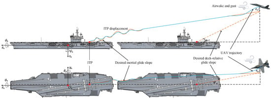
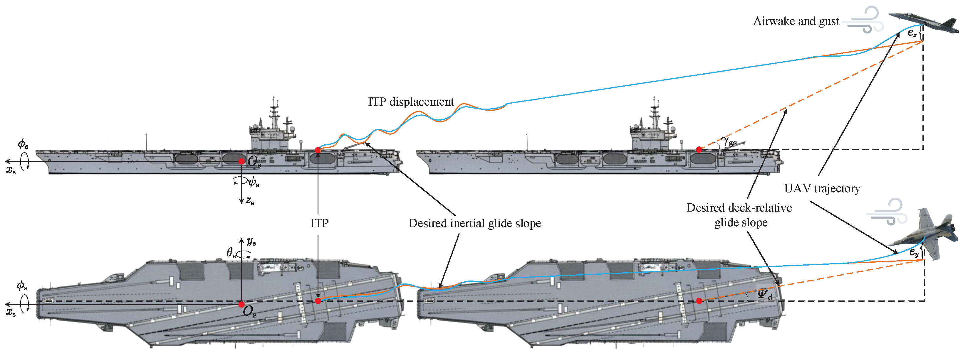
Figure 3 illustrates the carrier-landing process considered in this paper. The UAV is required to approach the deck-relative glide slope and converge to the neighborhood of the ITP under carrier airwake, gust disturbances, and deck motion.
Figure 3.
Carrier-landing process.
With , the desired glide slope is defined as
where is the deck-relative approach angle, and is the nominal glide-slope angle. The lateral and vertical tracking errors are and , respectively.
The control objective is to drive and into a small neighborhood of zero within a predefined time, while keeping the attitude errors of , , and inside prescribed performance bounds. Meanwhile, the angular rates and velocity should remain bounded under wind disturbances and actuator constraints. To achieve these objectives, the following sections develop a predefined-time direct lift/side-force controller, a predefined-time disturbance observer, and an anti-saturation mechanism for the direct-lift channel.
3. Preliminaries
3.1. Predefined-Time Convergence
Several preliminary lemmas on predefined-time convergence and stability analysis are introduced in this subsection.
Lemma 1
([29]). Let be an equilibrium point of the nonlinear dynamics with . Assume that a continuously differentiable positive definite Lyapunov function is available, satisfying and for all . If, along the system trajectory, there exist constants , , , , and such that
it follows that the system state is practically predefined-time stable. More specifically, for any , the trajectory reaches
no later than , and this time bound is independent of the initial condition. In the disturbance-free case , collapses to the origin, which implies predefined-time convergence of to zero.
Lemma 2
([2]). For nonnegative scalars , , and , the following inequalities hold:
Lemma 3
([36]). For any and , the smooth hyperbolic-tangent approximation satisfies
To facilitate numerical evaluation near the origin, define the regularized Lyapunov variable , where is a small positive threshold. Thus, for , whereas for .
3.2. Prescribed Performance
Prescribed performance control (PPC) is adopted to impose explicit transient and steady-state bounds on attitude tracking errors. For a generic error , the prescribed envelope is written as , where and determine the lower and upper bounds, respectively. The positive function decreases from its initial value to a small positive constant, thereby specifying both the transient allowable range and the final tracking accuracy.
Let denote the normalized error. Then, the PPC constraint is equivalent to . To convert the constrained error into an unconstrained variable, the following logarithmic transformation is used:
Therefore, boundedness of guarantees that remains inside the prescribed-performance envelope, while predefined-time convergence of further provides the desired convergence time property for the attitude loop error.
Assumption 3.
The initial attitude errors satisfy the prescribed-performance feasibility condition, namely, for .
Remark 2.
The logarithmic prescribed-performance transformation is well defined only for . The transformed error becomes unbounded as approaches either boundary and undefined once a boundary is violated, which constitutes the singularity issue in PPC. In this study, the preceding feasibility assumption ensures initial well-posedness, while the subsequent stability analysis guarantees that the prescribed-performance region is preserved under the stated conditions. If disturbances or actuator limitations make a fixed performance envelope temporarily infeasible, flexible or readjustable boundaries can be introduced to maintain transformation feasibility [37,38].
3.3. Observer Design
Consider a general affine nonlinear system with a lumped disturbance,
where , , and denote the state, control input, and lumped disturbance, respectively. Let and be the estimates of and , and define the observation error and disturbance estimation error as and , respectively.
The predefined-time disturbance observer (PTDO) is given by
where . Equations (15) and (16) give the coupled-error dynamics and . The observer gain is applied componentwise and selected as
where , , , , , , , and . Thus, has the positive lower bound . The aggregate state-observation Lyapunov function is . Under Assumption 1, the state observation error is practically predefined-time stable, while the disturbance estimation error is ultimately bounded by a residual that depends on the disturbance variation rate. The coupled-error derivation is provided in Section 5.
3.4. Anti-Saturation
Predefined-time control may require relatively large transient control effort, especially when the initial tracking error is large or rapid disturbance rejection is demanded. In practical carrier landing, however, the control surfaces and propulsion system are subject to physical limits. When the commanded input exceeds the available actuator range, the actual input cannot exactly follow the command, and the resulting input mismatch may degrade the predefined-time tracking performance. Therefore, an anti-saturation mechanism is introduced to compensate for the saturation effect.
For a control input , the actual saturated input is expressed as , where denotes the componentwise saturation function. The saturation error is defined as . For an affine subsystem , the saturated input can be rewritten as
Thus, actuator saturation acts as an additional matched input error in the closed- loop dynamics.
Assumption 4.
The saturation errors induced by the physical control-surface and thrust limits are bounded within the considered landing envelope.
To reduce the influence of this mismatch, an auxiliary anti-saturation variable is introduced as
where , , , and is the compensation gain matrix. The constants and are selected according to the predefined-time convergence form. According to Lemma 1, if the saturation error is bounded, can be driven into a small residual region within .
The auxiliary signal is incorporated into the controller design to compensate for the saturation-induced mismatch. As a result, the closed-loop system can preserve practical predefined-time stability under actuator constraints.
4. Controller Design
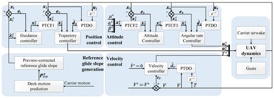
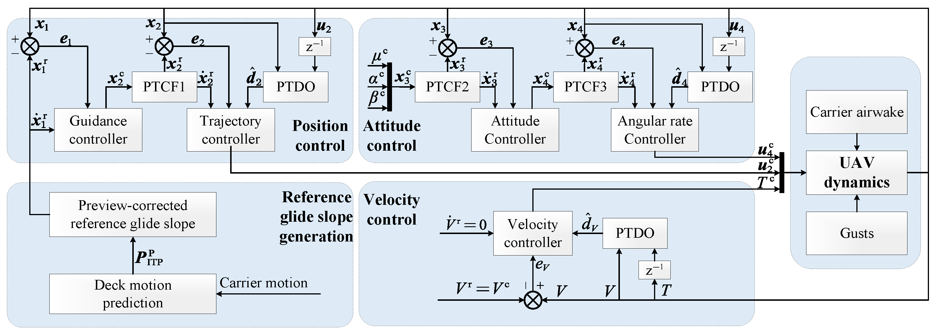
The overall automatic carrier landing system (ACLS) architecture is shown in Figure 4, where guidance, command filtering, predefined-time control, PTDO compensation, and anti-saturation modules are integrated to achieve accurate carrier landing under deck motion and wind disturbances.
Figure 4.
ACLS architecture.
4.1. Reference Glide Slope Generation
The nominal deck-relative glide slope is given in Equation (9). In the controller implementation, the short-term ITP sequence predicted from the deck motion is further used to improve the reference generation. Let the preview-corrected ITP position be
where denotes the preview correction. Since the vertical deck displacement is more pronounced during the terminal approach, the preview correction is mainly applied to the vertical ITP component, i.e., , where is the preview horizon, and is a bounded preview weight adjusted according to the predicted deck-motion trend.
By replacing in Equation (9) with , the position command is obtained. Its derivative is calculated from the ITP velocity and the UAV approach velocity along the inertial x-axis. The generated reference glide slope is then supplied to the position control loop.
Assumption 5.
The reference commands generated in the cascade control design and the derivatives required by the command filters and feedback laws are bounded.
4.2. Position Control
4.2.1. Position Outer Loop Design (Guidance Control)
The position outer loop generates the trajectory-angle command for lateral and vertical regulation. Based on Equation (1), the position dynamics can be written in the affine form
where , , and
The reference glide-slope generation provides the position command . In general, a command filter can be used to obtain a smooth reference signal. Since the position command varies slowly during the final approach, this loop directly sets and . Define the position tracking error as .
To derive the guidance command, the desired position-error dynamics is assigned as . The gain matrix is selected according to the predefined-time convergence form in Lemma 1, namely, , with
Here, is the candidate Lyapunov function of the jth position error, and , , , and are design parameters.
The desired derivative of is then obtained by . Substituting into Equation (21) gives the trajectory-angle command
where .
4.2.2. Position Inner Loop Design (Trajectory Control)
The trajectory loop tracks the heading and flight-path angle references generated by the guidance loop. To obtain smooth reference signals, the command is passed through a predefined-time command filter (PTCF1) using
where . For , the filter gain is selected as
where , and , , , and are design parameters.
Here, and denote the side force and lift after removing the direct-force input contributions, respectively.
The anti-saturation state is introduced into the flight-path reference to compensate for the trailing-edge-flap realization error. Let and let denote the flight-path component generated by Equation (19). The compensated trajectory reference is defined as
The nominal filtered derivative is retained in the control command, while the auxiliary-state dynamics compensates for the saturation mismatch in the resulting error system.
The auxiliary state is applied to the flap channel because its realization error acts directly through the flight-path-angle dynamics on vertical-position tracking, while all remaining actuator realization errors are retained in the composite stability analysis.
Define the trajectory tracking error as . The desired trajectory-error dynamics is assigned as , where . For ,
where , and , , , and are design parameters. Applying the PTDO in Equation (16) to gives the disturbance estimate . Then, the direct-force command is designed as
where .
4.3. Attitude Control
4.3.1. Attitude Outer Loop Design (Attitude Control)
The attitude outer loop generates the angular-rate command for tracking the bank-angle, angle-of-attack, and sideslip-angle references. In the proposed landing controller, the attitude command is specified as , where , , and . The command is passed through a predefined-time command filter, denoted as PTCF2, to obtain the smooth reference and its derivative.
Here, has the same predefined-time form as PTCF1. According to Equation (1), the attitude dynamics are written as
where , , and
Define the attitude tracking error as . For , the prescribed-performance constraint is imposed as , where and denote the upper and lower performance boundaries. Let and . The normalized error and transformed error are defined as and , respectively. Then, the derivative of the transformed error can be expressed as , where and .
Let , , and . The desired attitude state derivative is therefore given by
where the stabilizing term is selected as , , and
Here, , and , , , and are design parameters. Substituting into the attitude dynamics yields the angular-rate command
where .
4.3.2. Attitude Inner Loop Design (Angular-Rate Control)
The attitude inner loop tracks the angular-rate command and produces the conventional control surface commands. The angular-rate command is passed through a predefined-time command filter, denoted as PTCF3, to obtain the smooth reference and its derivative.
Here, has the same predefined-time form as PTCF1. According to Equation (1), the angular-rate dynamics are expressed as
where , , , and
In , , , and denote the known roll, pitch, and yaw moment components excluding the conventional control surface increments. They include the aerodynamic contributions of the flight states, angular rates, trailing-edge flap, and spoiler deflection.
Define the angular-rate tracking error as . The desired derivative is designed as
where , and
Here, , and , , , and are design parameters. Applying the PTDO in Equation (16) to gives the disturbance estimate . Substituting into the angular-rate dynamics yields the control-surface command
where .
4.4. Velocity Control
The velocity loop regulates the UAV airspeed by generating the thrust command. In this work, the velocity reference is selected as the trimmed approach velocity, denoted by . Since the approach velocity command is constant in the considered landing task, the reference is directly set as and .
According to Equation (1), the velocity dynamics can be written as
where T is the thrust, denotes the lumped velocity-channel disturbance, and
Here, D is the aerodynamic drag.
Define the velocity tracking error as . The desired velocity-error dynamics is assigned as
where the predefined-time gain is selected as
Here, , and , , , and are design parameters.
Applying the PTDO in Equation (16) to gives the disturbance estimate . Then, the desired velocity derivative is obtained as
Substituting into Equation (37) yields the thrust command
5. Stability Analysis
This section establishes the practical predefined-time stability of the complete closed-loop system by considering the cascade tracking errors, command-filter errors, disturbance-observer errors, and anti-saturation dynamics together.
Theorem 1.
Consider the UAV landing system in Equation (1) under Assumptions 1–5. Let the channel-wise coupling coefficients be defined by Equation (57). Suppose that the observer damping margins satisfy and that the controller, PTCF, and anti-saturation parameters satisfy the explicit sufficient conditions in Equation (58). Then, all closed-loop signals are bounded. Moreover, the complete augmented error reaches the residual set in Equation (63) no later than , independently of the initial condition. Consequently, the position, trajectory, angular-rate, and velocity tracking errors are practically predefined-time stable, while the attitude errors remain inside their prescribed-performance boundaries.
Proof.
For a scalar Lyapunov component , define
where , , , and are the parameters assigned to the channel indexed by ℓ.
For a scalar channel using the regularized variable , define its actual dissipation and maximum regularization loss as
where . For a component without a negative-power evaluation, set and . Because the regularized and ideal gains coincide for , one has
Let identify PTCF1–PTCF3. For , set . The filter equations in Section 4 give
where , , , and .
Before incorporating the PTDO terms into the composite analysis, the disturbance-estimation residual is derived from the coupled observer dynamics. Consider a scalar observer channel and abbreviate its state and disturbance estimation errors as and , respectively. Its error dynamics are and , where . Select a sufficiently small constant and define
The conditions and ensure that is positive definite. Differentiating it along the two error equations and applying Young’s inequality give
where . Hence, whenever , where . The joint estimation error is therefore bounded and ultimately enters this rate-dependent residual region. Applying the same argument componentwise gives a finite uniform bound for each vector observer, with its ultimate radius determined by the corresponding and observer gains.
The trajectory, angular-rate, and velocity channels employ separate PTDOs. Introduce and for . Using the first coupled observer-error relation given in Section 3.3,
where is a Young-inequality parameter, and , , and . The remaining linear damping margin and the observer residual are defined as and , respectively. The latter is bounded under Assumption 1 and the joint observer-error analysis above. Consequently, the total observer Lyapunov function and residual are and , respectively.
Choose , and let . For arbitrary , , and , the Cauchy–Schwarz and Young inequalities yield
Let be the realization error of the spoiler and trailing-edge-flap commands. Differentiating and using Equations (25) and (26) result in
With , , and positive constants , , and , one has
The relation , together with Equations (29) and (31), gives . Select . Over the feasible PPC domain, let . For and ,
Boundedness of guarantees , and therefore ensures that the attitude tracking errors remain within their prescribed-performance boundaries.
Choose . The continuous realization of the robust term in Equation (19) introduces , where . Lemma 3 gives , and hence . Applying Young’s inequality to then gives
where is the coefficient introduced by the bounded saturation input, and contains and the remaining bounded saturation residuals.
The composite Lyapunov function is selected as
Define the augmented error vector explicitly as
so that .
To specify every scalar component in Equation (54), define
where , , , and . Thus, denotes the scalar Lyapunov component associated with ; for example, , , and .
Combining Equations (44)–(53) gives the expanded composite bound
where collects the bounded observer, actuator, anti-saturation, and reference-related residual terms not assigned to the quadratic coefficients. The total positive quadratic coefficients are therefore defined as
Let contain the scalar components associated with the coefficients in Equation (57). By Equation (43), define and . Equation (56) can then be written as
For every , the arithmetic–geometric mean inequality gives . Consequently, the explicit channel-wise sufficient conditions are
Under Equation (58), define the retained dissipation margins as
The preceding lower bound implies for every . Therefore, summing the component-wise inequalities yields
The implementation adopts a common exponent for all predefined-time channels. Let , and define
Here, the superscripts ) and correspond to the powers and , respectively. By Lemma 2,
Hence,
For any , define
The residual set of the complete cascade is
Because , the corresponding aggregate error bound is . Finally, define the equivalent aggregate predefined-time parameter as . Equation (62) has the form of Lemma 1 with , , and as defined above. Therefore, reaches within . The coefficients , , and depend on the selected channel parameters, the retained dissipation margins, and , but not on . Thus, the time bound is independent of the initial condition. When , the residual set reduces to the origin. In addition, boundedness of guarantees that the bank-angle, angle-of-attack, and sideslip-angle errors remain inside their prescribed-performance boundaries. □
6. Simulations
To validate the proposed control scheme, numerical simulations were conducted using a nonlinear six-DOF fixed-wing UAV model in the carrier landing phase. First, the predefined-time convergence property was tested under different initial approach errors. Second, the benefit of the integrated direct lift and side-force architecture was examined by comparing it with reduced direct-force configurations. Third, the complete Predefined-Time Direct Lift/Side-Force-Integrated Approach Landing (PTDIAL) controller was compared with several baseline controllers to evaluate tracking accuracy, attitude response, actuator behavior, and disturbance-rejection capability. Finally, Monte Carlo simulations were performed to assess robustness under randomized initial errors, airwake intensity, sea state scale, and gust parameters.
6.1. Simulation Setup
The initial longitudinal position of the UAV was set as , where the nominal ITP was located at at the initial instant. Unless otherwise specified, the initial vertical and lateral offsets were and , respectively. For the predefined-time convergence test, several different initial offsets were additionally used to verify the convergence behavior under different approach errors.
The UAV was initialized at the trimmed approach condition. The trim airspeed was , the trim angle of attack was , and the trim sideslip angle, bank-angle, and angular rates were set to zero. The flight-path angle and heading angle were determined by the nominal glide-slope geometry and ship motion. The elevator, thrust, and flap trim values were obtained from the nonlinear trim calculation and then kept as the initial actuator commands.
The principal controller and PTDO parameters used in all simulation scenarios are summarized in Table A5 and Table A6, respectively, while the actuator settings are given in Table A3.
Three simulation scenarios were considered, as summarized in Table 1. Scenario 1 was used to verify the predefined-time convergence property. Scenario 2 was used to evaluate the effectiveness of the integrated direct lift/side-force architecture. Scenario 3 was used for controller comparison and Monte Carlo verification under combined disturbances. The carrier airwake was modeled according to the MIL-F-8785C standard [35], and the Ideal Touch Point (ITP) motion under different sea states was generated according to the method in the reference [9]. Scenario 2 included a lateral gust with an amplitude of , injected at . In Scenario 3, a lateral gust with an amplitude of was injected at , and a vertical gust with the same amplitude was injected at .
Table 1.
Simulation scenarios.
The comparison algorithms are summarized in Table 2. Scenario 2 varied the direct-force configuration to isolate its contribution, whereas Scenario 3 retained the integrated direct lift/side-force architecture to compare the control laws, disturbance observers, and anti-saturation mechanism. Within each scenario, all methods used the same nonlinear model, flight condition, reference, actuator constraints, and environmental realization. PTDIAL-NA retained the parameters of PTDIAL with only the flap anti-saturation mechanism disabled; FxTDI and NDI, constructed following [3] and [39], respectively, were independently tuned under the same nominal scenario. The selected parameters remained fixed, and identical randomized cases were used in the Monte Carlo comparison.
Table 2.
Comparison algorithms.
6.2. Predefined-Time Convergence Verification
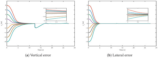
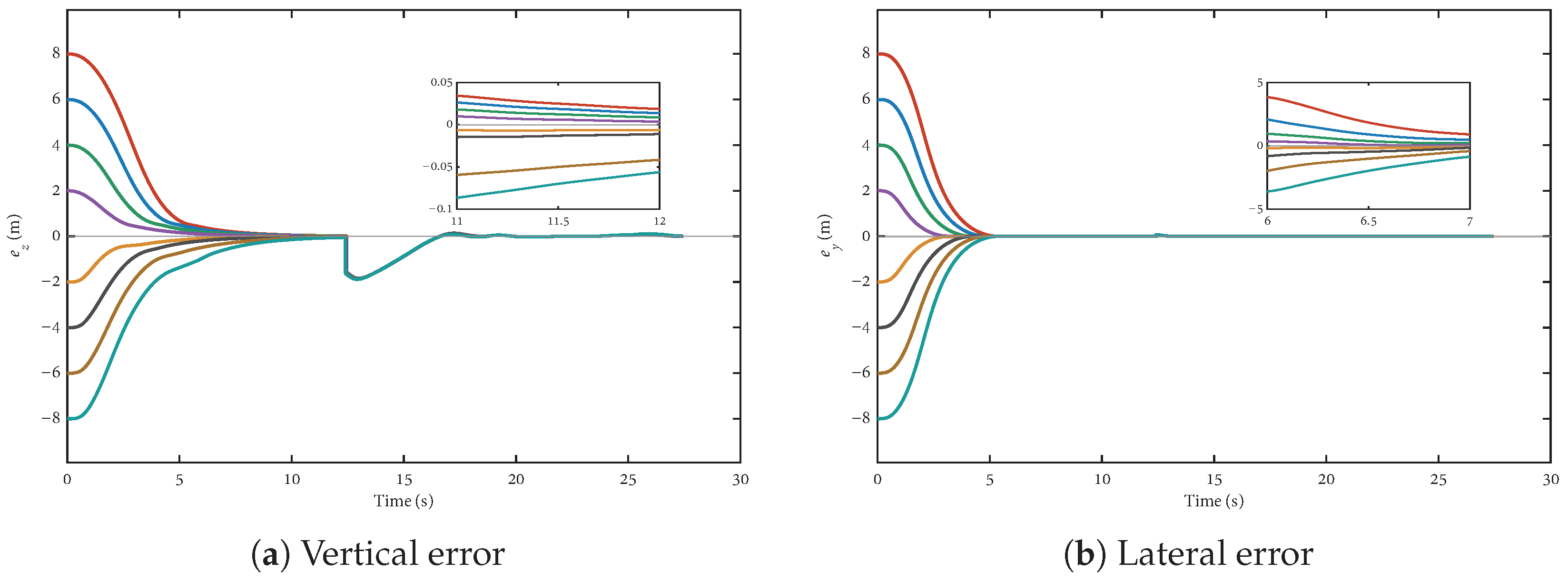
To evaluate predefined-time convergence, the initial error in each position channel was set to , , while the remaining states were initialized near the trim condition; the eight colored curves in each panel correspond, respectively, to these initial offsets. The position-loop design times were and , with convergence recorded when the corresponding error entered and remained within its bounded steady-state neighborhood.
Figure 5 shows that all lateral and vertical errors converge within and , respectively, with little variation across the tested initial values. The vertical transient caused by the subsequent ITP motion is also rejected. Scenario 1 isolates the effect of the initial conditions, whereas Section 6.4 and Section 6.5 examine combined and randomized disturbances; under the conditions of Theorem 1, the convergence-time bound remains independent of the initial state.
Figure 5.
Position-error responses under different initial offsets.
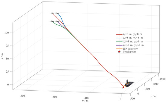
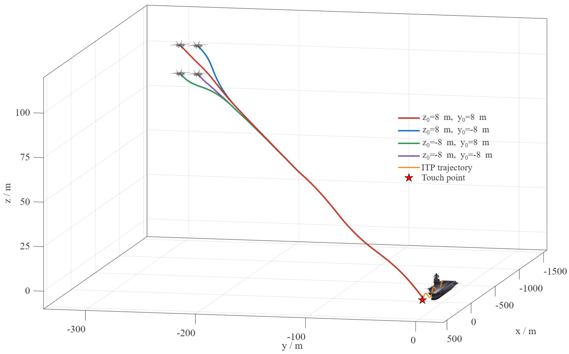
To further illustrate the approach process, Figure 6 presents the three-dimensional landing trajectories under four extreme initial conditions. The UAV starts from different vertical and lateral offsets and finally approaches the neighborhood of the ITP. This result further verifies the effectiveness of the predefined-time guidance and the integrated direct lift/side-force control architecture.
Figure 6.
Three-dimensional landing trajectories.
6.3. Direct-Force Architecture Validation
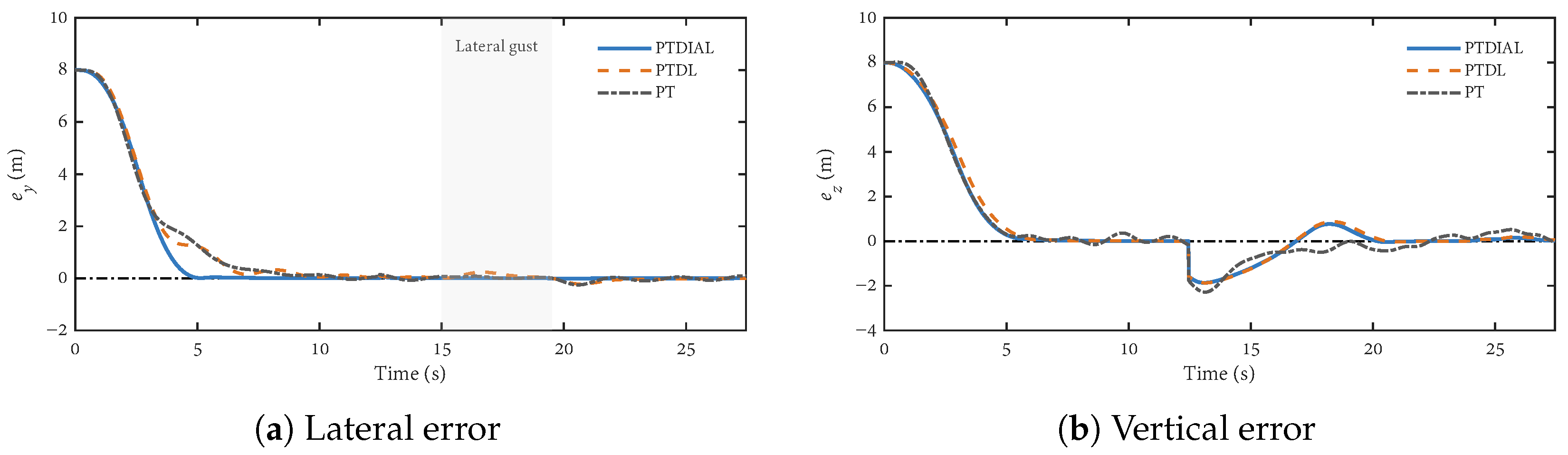
The effectiveness of the integrated direct-force architecture was evaluated by comparing PTDIAL with two reduced configurations, namely, PTDL and PT. PTDIAL used both direct lift and direct side force, PTDL retained only the direct-lift channel, and PT removed both direct-force channels. This comparison was used to isolate the contribution of direct lift and direct side force to carrier landing control.
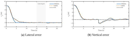
Figure 7 shows the position tracking results of the three control architectures. Compared with PTDL and PT, PTDIAL achieves faster and smoother lateral error convergence. This result indicates that the direct side-force channel can effectively reduce the dependence on bank-angle-induced lateral motion and improve lateral tracking performance. In the vertical channel, the direct-lift channel helps reduce the coupling between vertical motion and pitch attitude, leading to improved vertical tracking behavior compared with the non-direct-force configuration.
Figure 7.
Position tracking results of different direct-force architectures.
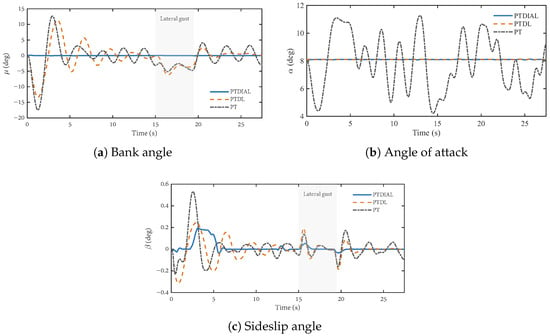
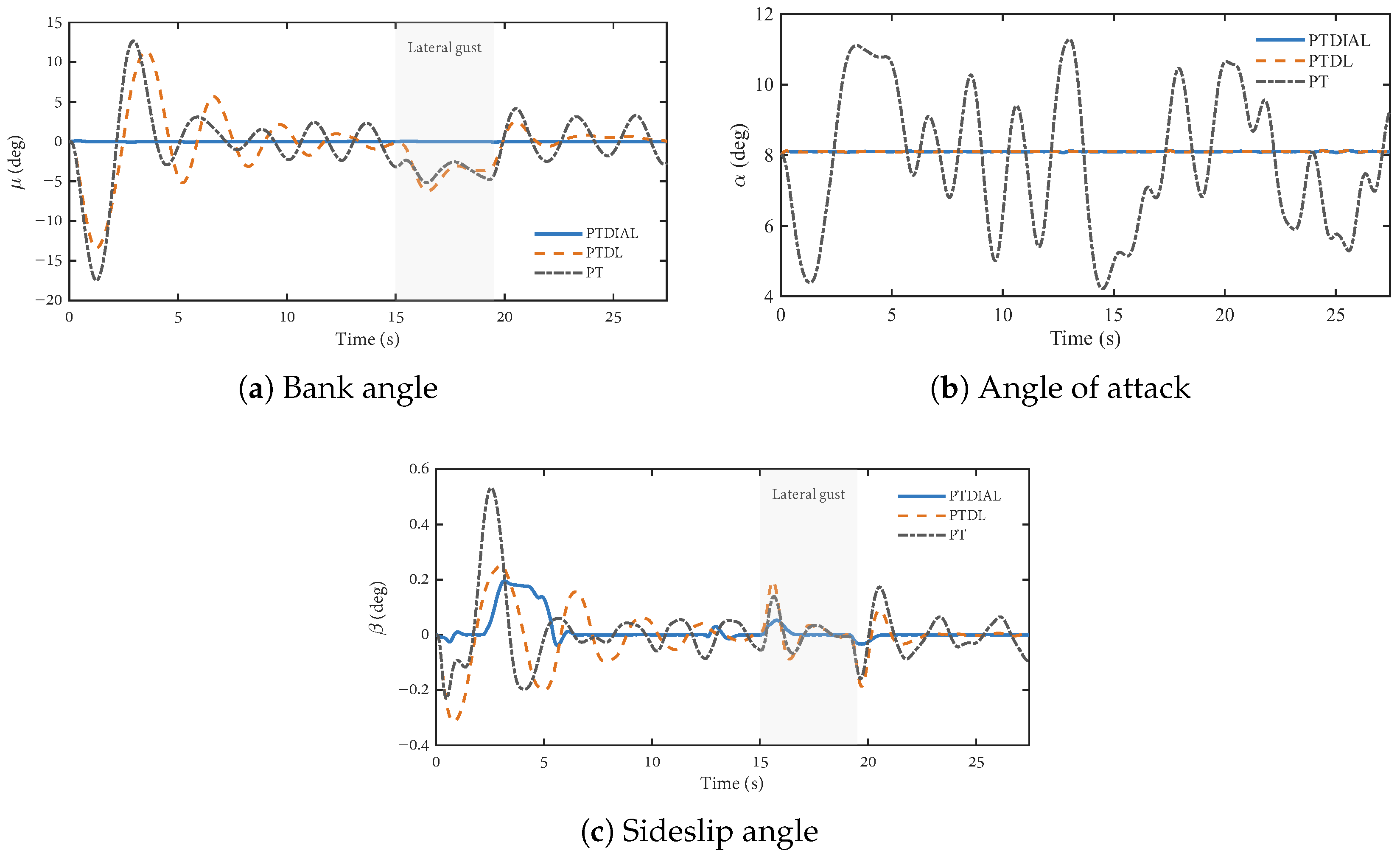
Figure 8 presents the attitude responses. In the bank-angle channel, PTDIAL keeps almost unchanged, since the spoiler-generated side force allows the UAV to correct the lateral error without relying on bank-angle/sideslip-mediated lateral correction. By contrast, PTDL and PT require evident bank-angle variations. In the angle-of-attack channel, PT shows large oscillations, whereas PTDIAL and PTDL remain close to the trim value due to the use of direct lift. In the sideslip channel, PTDIAL maintains near zero with only small transient fluctuations, which are mainly related to the residual coupling introduced by spoiler-based side-force generation. The other two configurations exhibit more persistent sideslip oscillations.
Figure 8.
Attitude responses of different direct-force architectures.
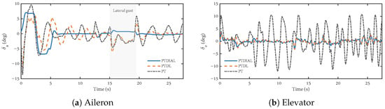
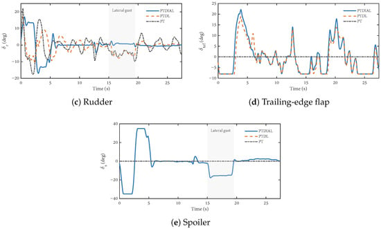
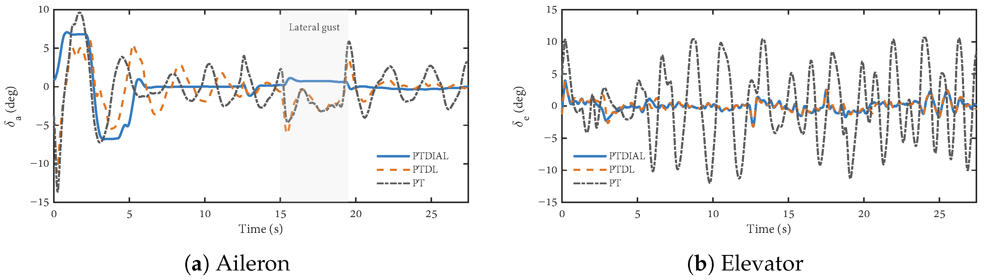
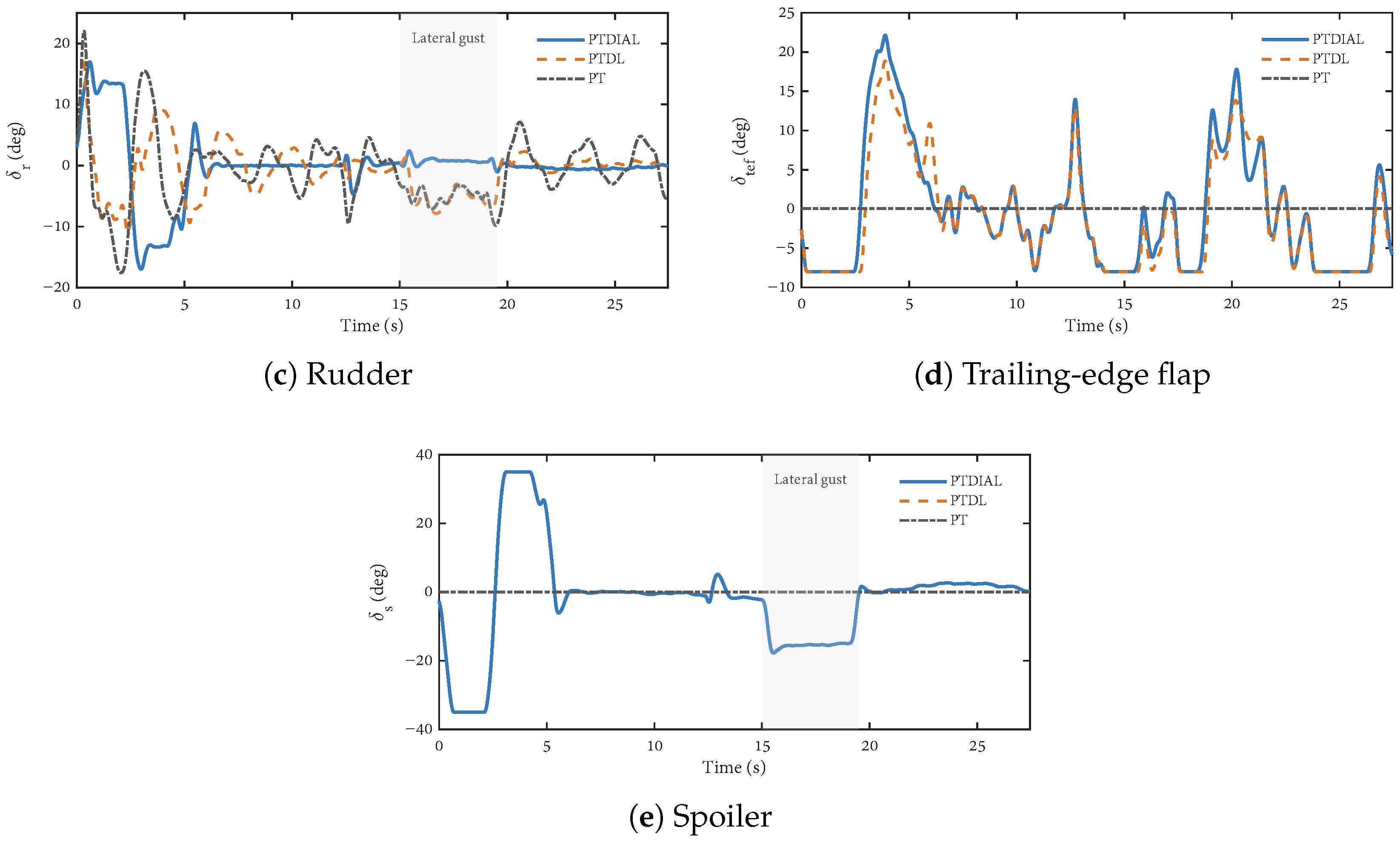
Figure 9 shows the actuator responses. PTDIAL makes use of both the flap and spoiler channels to generate direct vertical and lateral forces. Although this introduces additional direct-force actuator activity, it reduces the demand on attitude maneuvering and improves the coordination of the landing control process. Overall, the results demonstrate the effectiveness of the integrated direct lift/side-force architecture under large initial position deviations and lateral disturbance.
Figure 9.
Actuator responses of different direct-force architectures.
6.4. Controller Comparison Under Combined Disturbances
Scenario 3 was used to evaluate the closed-loop performance of different controllers under combined ITP motion, carrier airwake, and gust disturbances. The compared controllers are those listed in Table 2.
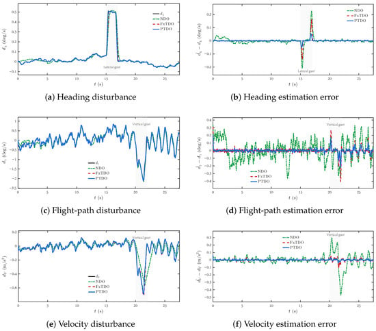
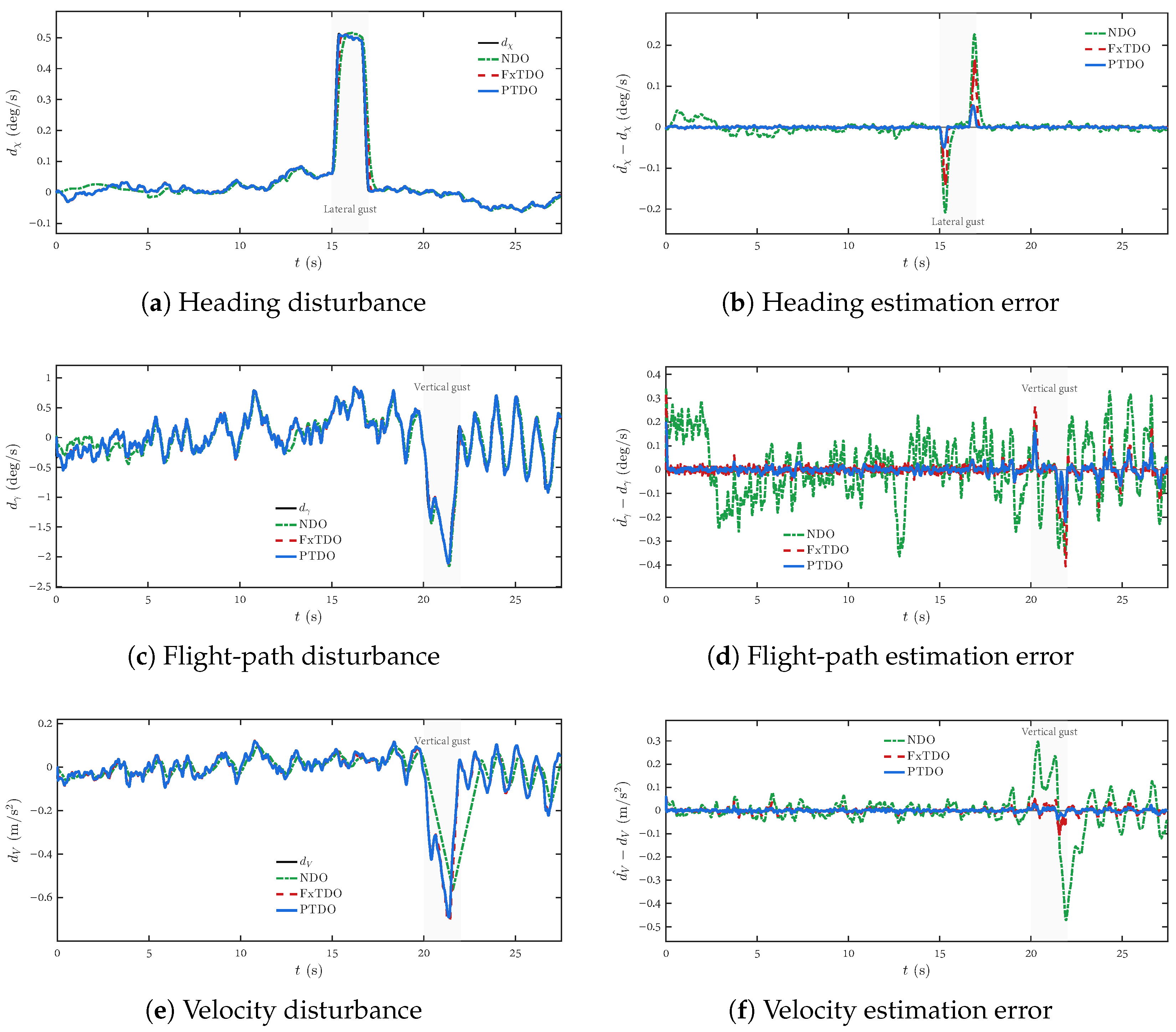
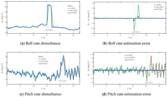
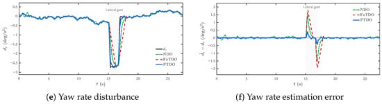
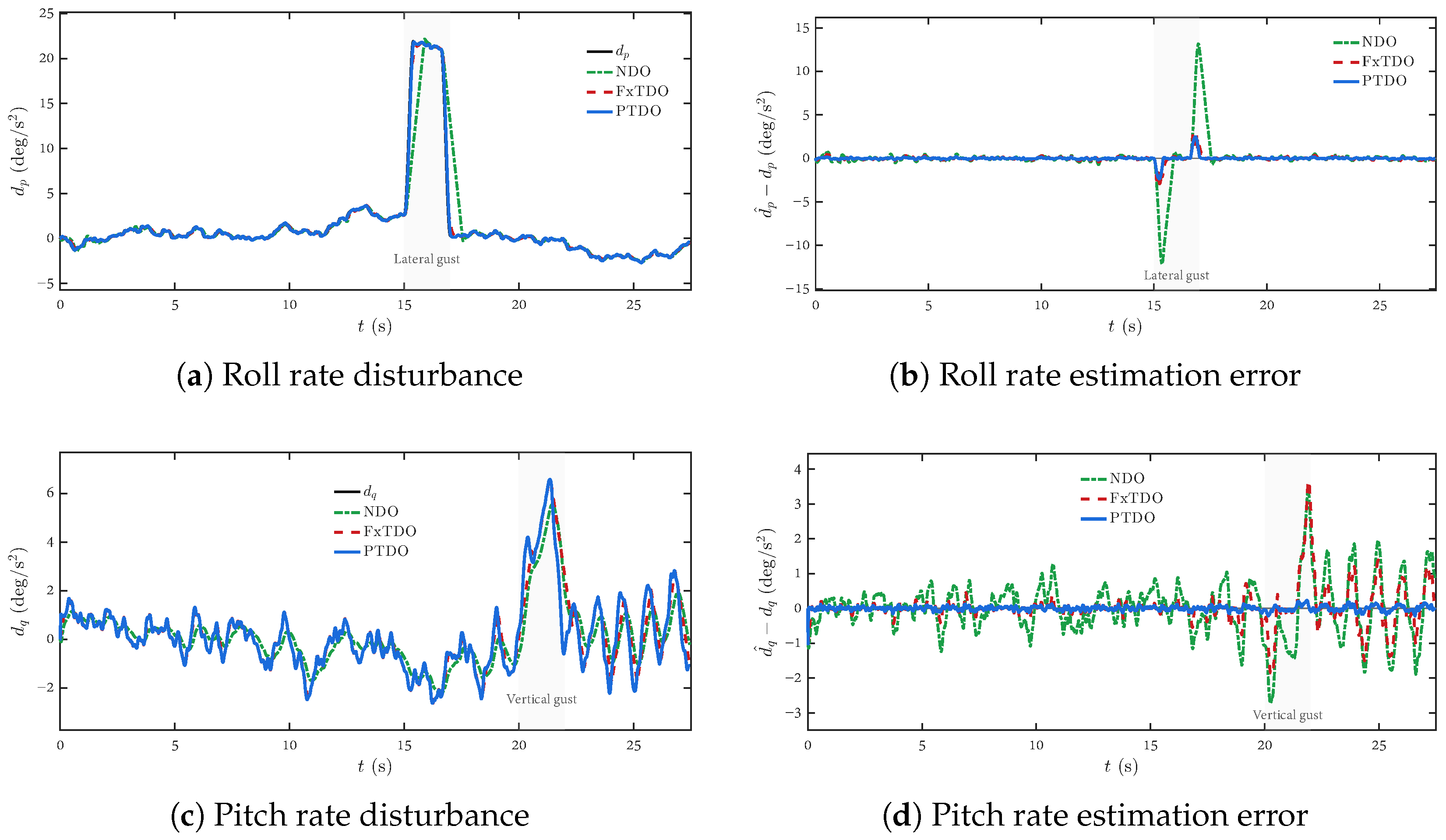
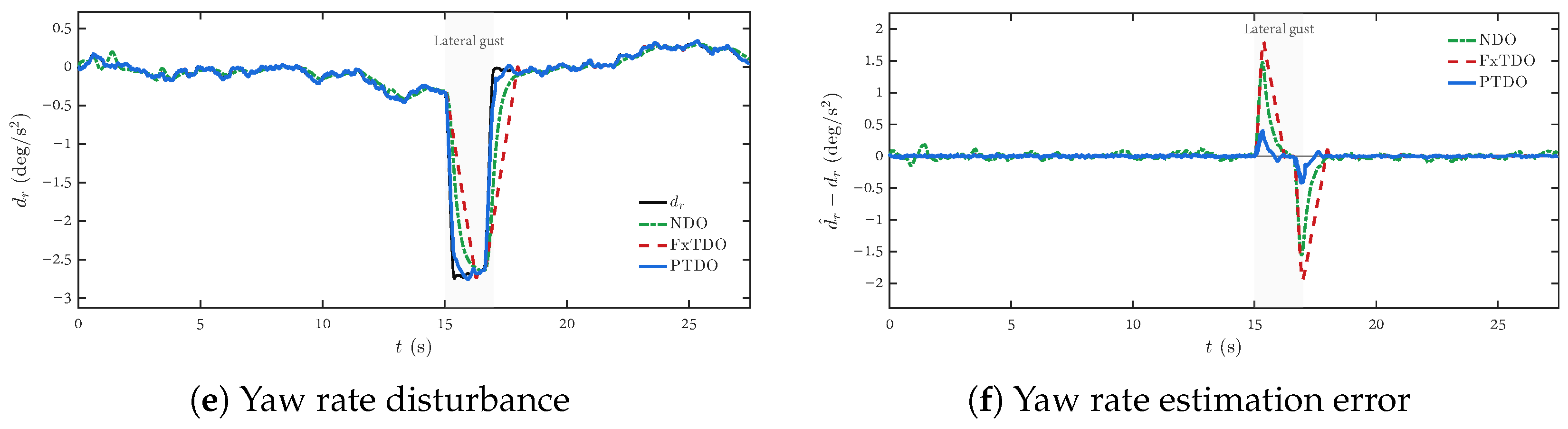
Before presenting the closed-loop responses, the disturbance-observer performance is examined. The proposed predefined-time disturbance observer, denoted as PTDO, was compared with FxTDO and NDO in six channels, including heading, flight-path, roll rate, pitch rate, yaw rate, and velocity disturbances.
Figure 10 and Figure 11 present the disturbance-observer comparison. For each disturbance channel, the estimated disturbance and the corresponding estimation error are shown together to provide a direct comparison of tracking accuracy and residual error. In the heading, roll rate, and yaw rate channels, PTDO provides faster and more accurate tracking of the disturbance variation caused by the lateral gust. In the flight-path, pitch rate, and velocity channels, PTDO also maintains smaller estimation errors during the vertical gust response. Compared with FxTDO, PTDO reduces the phase lag and improves the transient tracking accuracy. Compared with NDO, PTDO captures the disturbance variations more effectively, whereas NDO tends to produce smoother but delayed estimates. These results indicate that the proposed predefined-time observer can provide more accurate disturbance information for feedforward compensation and closed-loop control.
Figure 10.
Disturbance estimation and estimation-error comparison in the heading, flight-path, and velocity channels.
Figure 11.
Disturbance estimation and estimation-error comparison in the angular rate channels.
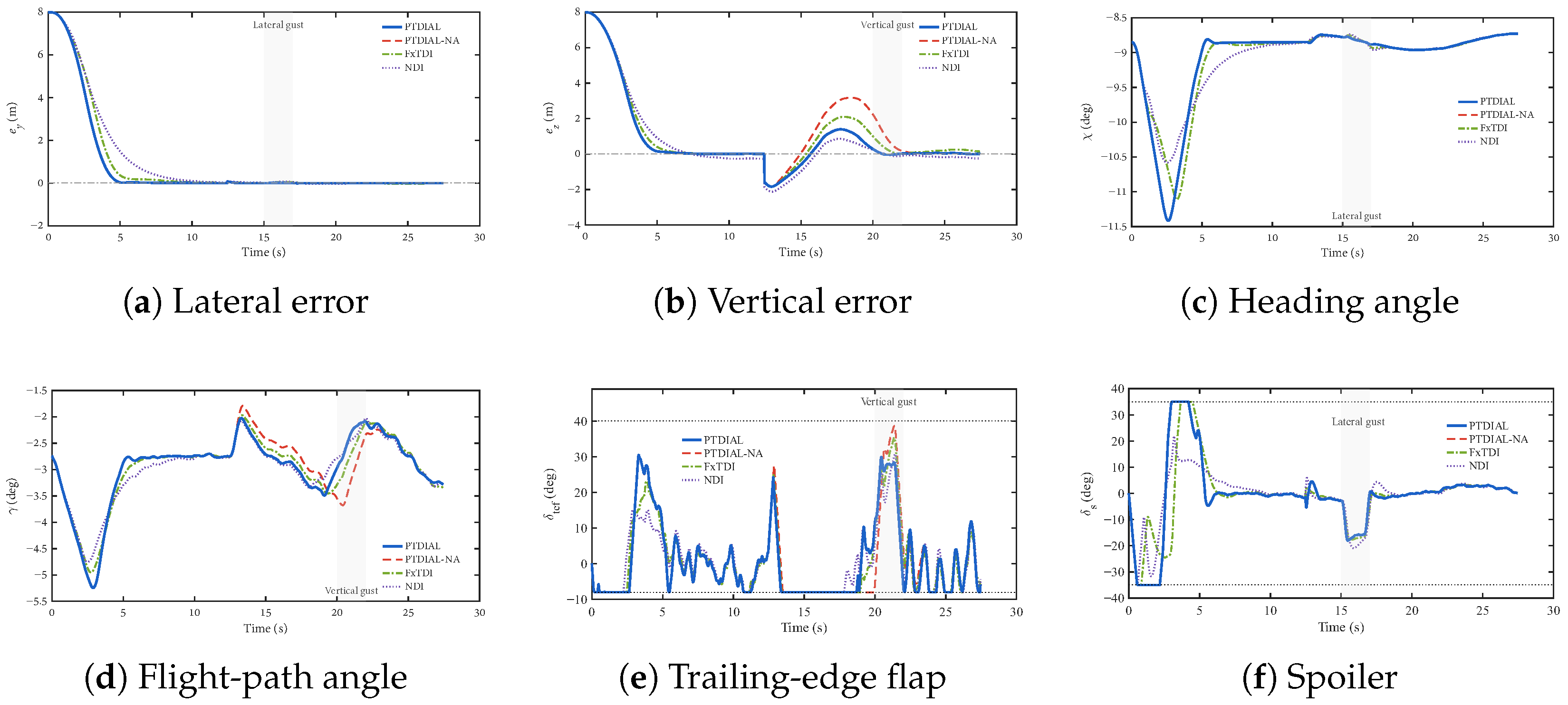
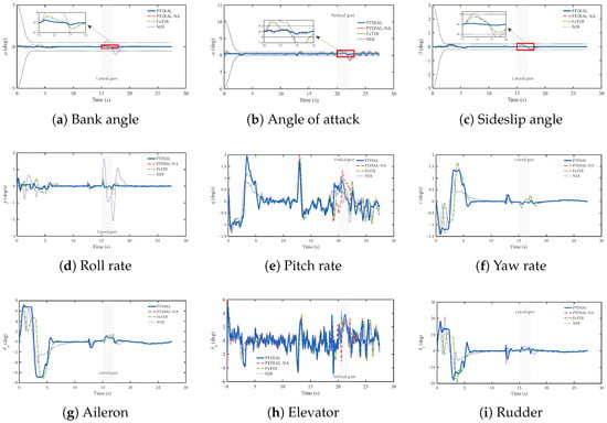
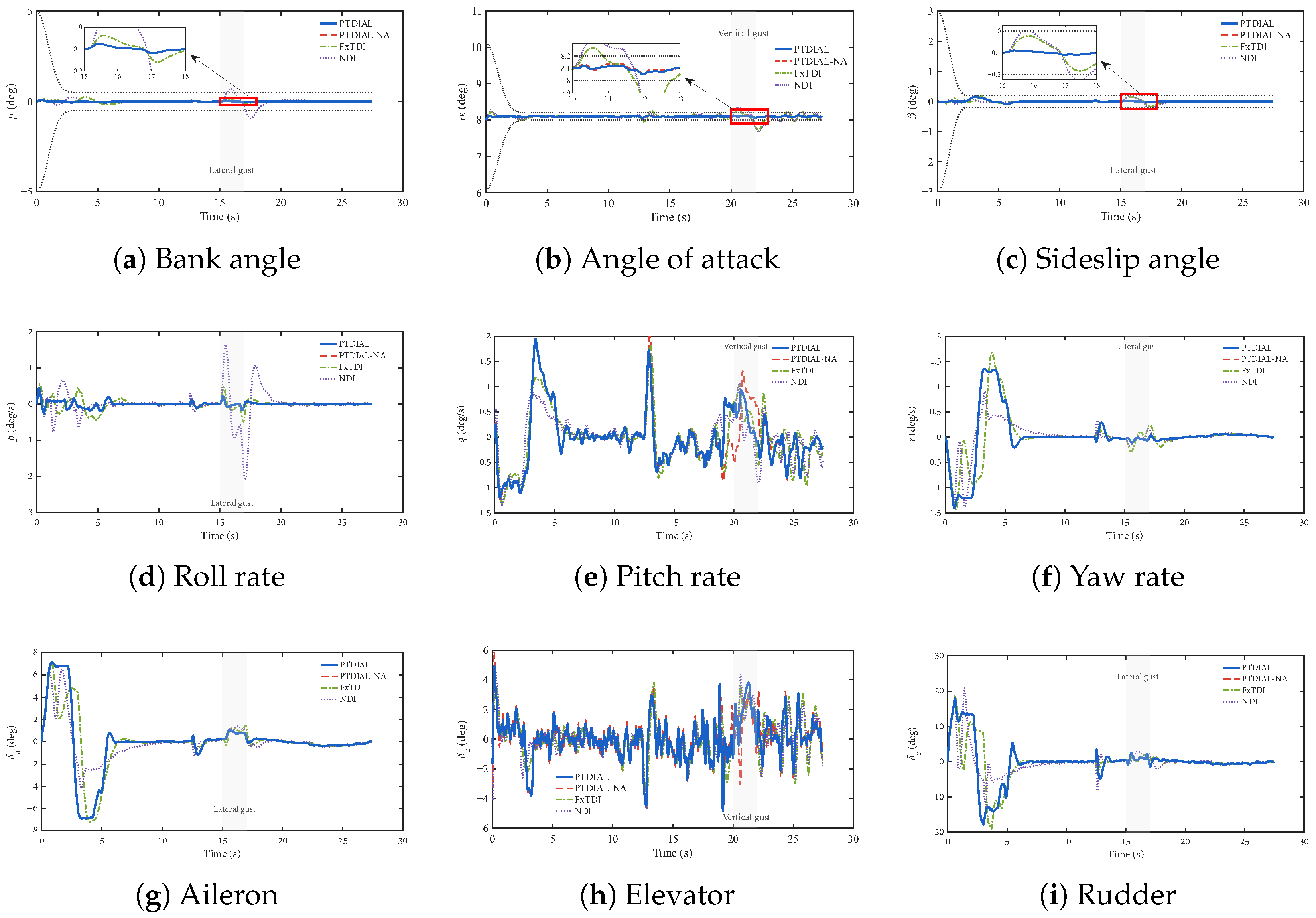
The closed-loop responses under Scenario 3 were further organized according to the control architecture, as shown in Figure 12, Figure 13 and Figure 14. Figure 12 presents the position-loop-related responses, including the lateral and vertical position errors, the trajectory variables, and the direct-force actuators. All controllers reduce the initial position errors, while PTDIAL gives a smoother response under the combined deck motion and gust disturbances. Since the four methods use the same integrated direct lift/side-force architecture, the differences in this scenario mainly reflect the effects of the observer, predefined-time control law, and anti-saturation mechanism.
Figure 12.
Position-control-related responses.
Figure 13.
Attitude-control-related responses.
Figure 14.
Velocity-control-related responses.
Figure 13 shows the attitude-loop responses and the conventional aerodynamic control surfaces. Owing to the use of direct-force control, the attitude variables are well regulated for all four methods, especially in the bank-angle and sideslip channels. During gust injection, PTDIAL and PTDIAL-NA exhibit smaller fluctuations in several channels, which is consistent with the improved disturbance-estimation accuracy shown above. The attitude responses also show that the proposed controller maintains the prescribed performance bounds while preserving small attitude deviations.
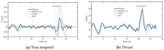
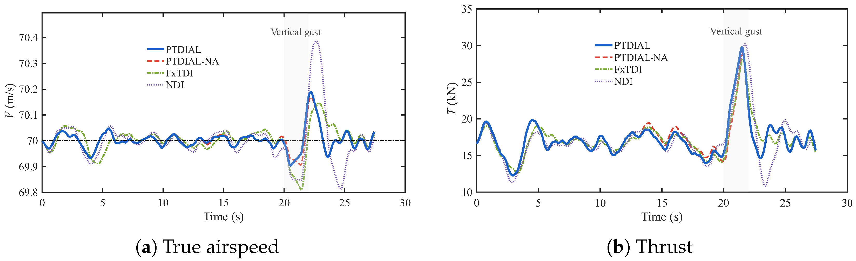
The velocity-loop responses are shown in Figure 14. The airspeed is maintained near its reference value under combined disturbances, and the thrust response remains bounded. Together with the actuator responses in Figure 12, the results indicate that the predefined-time requirement inevitably leads to relatively large transient commands, especially in the direct-lift channel. Without anti-saturation compensation, PTDIAL-NA produces a longer flap saturation interval, which further affects the vertical error, flight-path angle, angle-of-attack, pitch rate, and elevator response. By contrast, the proposed PTDIAL shortens the flap saturation duration and alleviates the coupled longitudinal response. These results indicate that the anti-saturation mechanism is not only used to limit actuator commands but also helps maintain the transient quality of the predefined-time closed-loop system under actuator constraints.
Overall, the comparison demonstrates that PTDIAL achieves a favorable balance among predefined-time convergence, disturbance rejection, attitude regulation, and actuator feasibility. Because the compared controllers share the same direct-force architecture, the improvement mainly comes from the combined action of the predefined-time prescribed performance controller, the predefined-time disturbance observer, and the flap anti-saturation design.
6.5. Monte Carlo Verification
To further evaluate robustness against uncertain landing conditions, Monte Carlo simulations were conducted based on Scenario 3. A total of 20 random cases were considered. In each case, the initial vertical and lateral offsets were randomly selected within 4– with random signs. The carrier airwake level was randomly selected from light, moderate, and heavy conditions, the airwake scaling factor was varied within –, and the deck motion scale was varied within –. In addition, lateral and vertical gusts with random injection times, durations, and amplitudes were imposed. The same random cases were applied to all compared controllers to ensure a fair comparison.
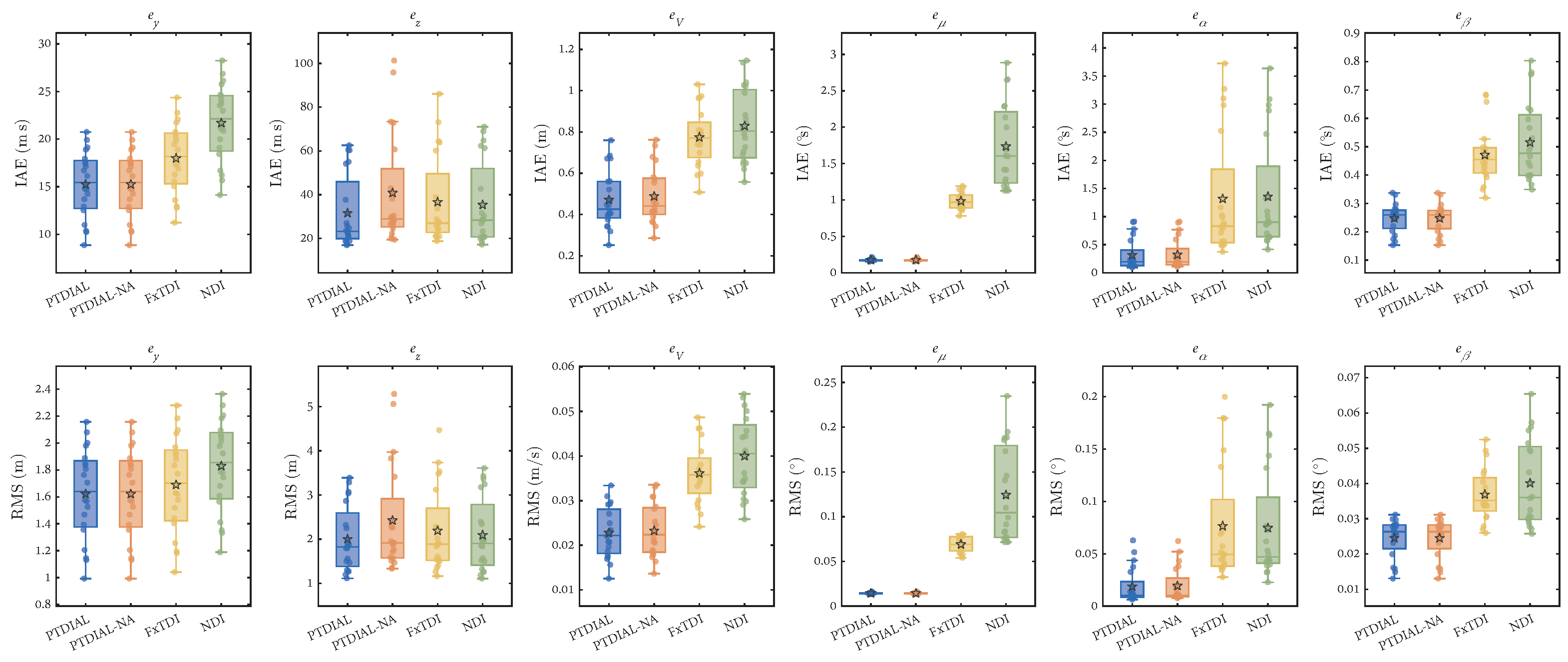
Figure 15 shows the boxplots of the IAE and RMS values for the position, velocity, and attitude tracking errors. For an error signal , these two indices are defined as and . In both Monte Carlo figures, the five-pointed stars denote the sample means. All controllers complete the landing task in the tested cases. Compared with FxTDI and NDI, PTDIAL produces more compact error distributions in most channels, especially for the vertical position tracking error , velocity error , and attitude errors. PTDIAL-NA shows similar lateral and attitude tracking performance to PTDIAL, but its vertical-channel performance is more sensitive to actuator saturation. These results indicate that the proposed observer and predefined-time control structure improve the consistency of the closed-loop response under randomized disturbances.
Figure 15.
Monte Carlo comparison of IAE and RMS tracking metrics.
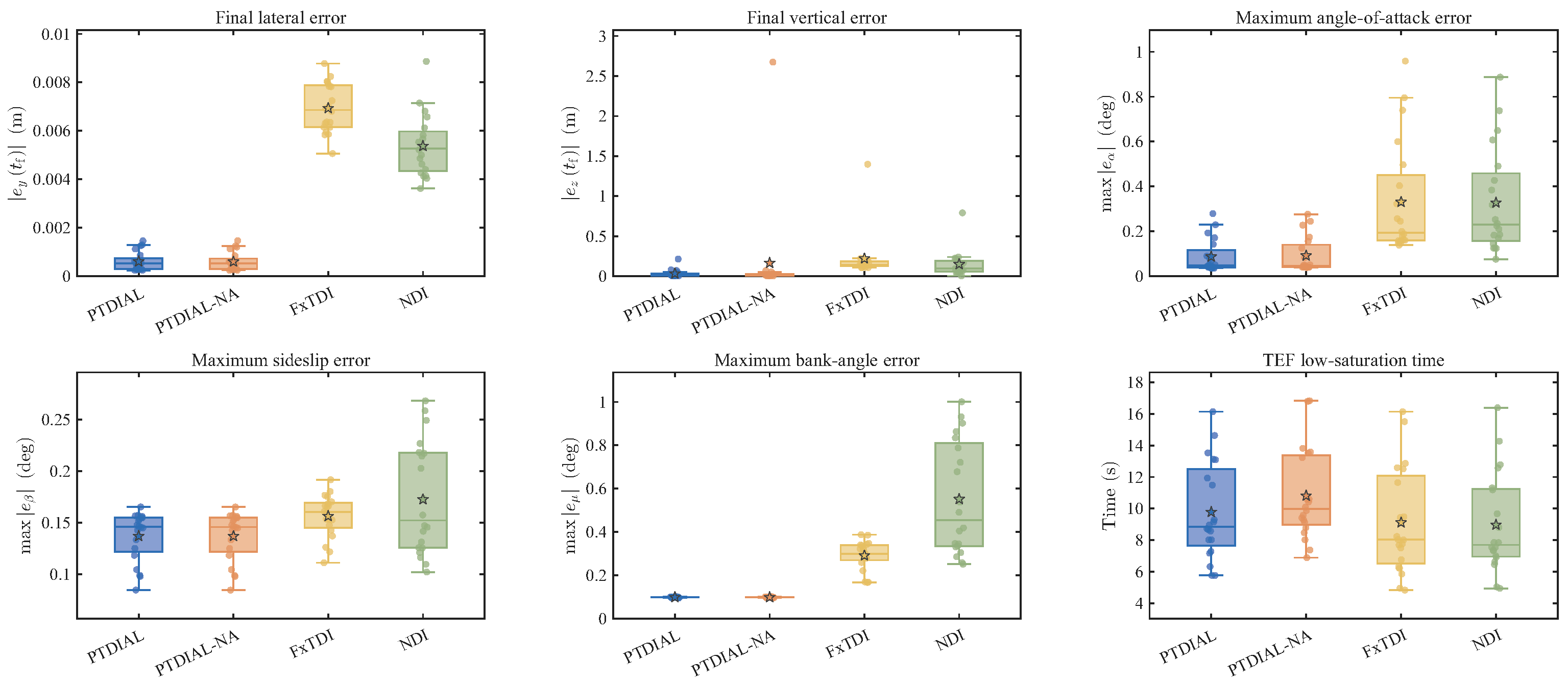
Additional quantitative metrics are further compared in Figure 16, including the terminal position errors, the maximum attitude errors, and the flap low-saturation time. PTDIAL maintains small terminal errors and reduced maximum attitude deviations over the tested cases. Although the lower-gain baseline controllers may naturally spend less time near the flap lower limit, their tracking and attitude metrics are generally less favorable. By comparing PTDIAL with PTDIAL-NA, it can be observed that the anti-saturation mechanism reduces the adverse influence of flap saturation on the vertical channel and the coupled longitudinal response. Therefore, the Monte Carlo results further confirm that PTDIAL provides a more reliable balance between tracking accuracy, disturbance rejection, and actuator feasibility.
Figure 16.
Monte Carlo comparison of quantitative metrics.
The numerical statistics corresponding to Figure 15 and Figure 16 are summarized in Table 3 and Table 4, respectively, as the mean ± standard deviation.
Table 3.
Monte Carlo statistics of the tracking metrics.
Table 4.
Monte Carlo statistics of the landing-related metrics.
7. Conclusions
This paper proposed a predefined-time integrated direct lift/side-force control method for carrier-based fixed-wing UAV landing. The trailing-edge flap and spoiler were employed to generate direct lift and side force, respectively, allowing position corrections to be achieved with reduced attitude-mediated motion. A preview-based reference glide slope was combined with predefined-time control, prescribed-performance attitude regulation, predefined-time disturbance observation, and trailing-edge flap anti-saturation compensation. Theoretical analysis showed that the closed-loop tracking, filtering, observation, and auxiliary errors were practically predefined-time stable under the stated assumptions.
Simulation results demonstrated that the integrated direct-force architecture improved vertical and lateral tracking while maintaining small angle-of-attack, bank-angle, and sideslip variations. The proposed disturbance observer enhanced the rejection of airwake and gust disturbances, while the anti-saturation mechanism shortened the flap saturation duration and mitigated its coupled influence on the vertical channel. Comparisons with reduced direct-force configurations, fixed-time control, and nonlinear dynamic inversion confirmed the overall performance advantage of PTDIAL. The Monte Carlo results further demonstrated consistent tracking accuracy, attitude regulation, and actuator feasibility under randomized landing conditions. Future work will focus on aerodynamic uncertainty, multi-actuator control allocation, actuator faults, and hardware-in-the-loop or flight-test validation.
Author Contributions
Conceptualization, Z.P. and J.W.; methodology, Z.P.; software, S.S.; validation, Z.P.; formal analysis, B.W.; investigation, B.W.; resources, X.S.; data curation, S.S.; writing—original draft preparation, Z.P.; writing—review and editing, D.Y.; visualization, Z.P.; supervision, D.Y.; project administration, W.H. All authors have read and agreed to the published version of the manuscript.
Funding
This research received no external funding.
Data Availability Statement
The data and simulation code used in this study are available from the corresponding author upon reasonable request.
DURC Statement
Current research is limited to theoretical and simulation-based automatic aircraft landing control, which is beneficial for improving landing safety and reliability and does not pose a threat to public health or national security. Authors acknowledge the dual-use potential of the research involving automatic carrier landing control and confirm that all necessary precautions have been taken to prevent potential misuse. As an ethical responsibility, the authors strictly adhere to relevant national and international laws about DURC. The authors advocate for responsible deployment, ethical considerations, regulatory compliance, and transparent reporting to mitigate misuse risks and foster beneficial outcomes.
Conflicts of Interest
The authors declare no conflicts of interest.
Appendix A
Table A1.
Abbreviations and symbols.
The nonlinear six-DOF model used in the simulation is summarized in this appendix. The physical and inertial parameters used in the simulations are listed in Table A2.
Table A2.
Physical and inertial parameters of the UAV model.
The translational and trajectory dynamics are given by
where T is the actual thrust, and g is the gravitational acceleration.
The physical control-surface realizations used in the simulations follow first-order dynamics subject to the position and rate constraints summarized in Table A3. In Figure 2, the engine dynamics from the thrust command to the actual thrust T are represented by
The conventional-surface dynamics, position envelopes, and engine model were selected with reference to the carrier-landing models in [8,33], and the flap model was benchmarked against the actuator configuration in [2]. The direct-force actuator parameters used in the simulations are also stated explicitly in the table.
Table A3.
Actuator and engine models and constraints.
The attitude kinematics and angular rate dynamics are expressed as
The Euler-angle relations used in the simulation are
The aerodynamic forces and moments in Figure 2 are defined as
where L, D, and Y denote the lift, drag, and side force, respectively; , , and denote the roll, pitch, and yaw moments, respectively. The overbar on is used to distinguish the roll moment from the lift force L. In addition, is the dynamic pressure, S is the wing reference area, b is the wing span, is the mean aerodynamic chord, and is the air density.
For the adopted UAV model, the aerodynamic coefficients are expressed as
The numerical coefficients corresponding to Equation (A5) are listed in Table A4. All angular variables and control-surface deflections in these expressions are measured in radians.
Table A4.
Numerical aerodynamic coefficients used in the simulations.
The spoiler variables used in the aerodynamic model are defined as
In the trajectory-loop vector input in Equation (1), denotes the direct side-force command and is implemented as the differential spoiler deflection, i.e., . The symmetric spoiler component mainly affects lift and drag, whereas generates direct side force and lateral-directional moments.
The signed differential command is allocated to the physical spoilers by
The allocation satisfies . For , the resulting components are and . Both components are retained in the aerodynamic coefficients in Equation (A5).
The wind-induced equivalent disturbance terms are computed from the angle-of-attack and sideslip perturbations and . The corresponding aerodynamic increments are
Thus, the lumped disturbances are
The inertia-related coefficients in the angular rate equations are
For reproducibility, the principal numerical settings of the proposed controller and the PTDOs are summarized below. For all controller channels, the common double-power parameters were , , and , and the regularization threshold was . The predefined-time parameters are listed in Table A5; entries within each vector follow the channel order shown in the second column.
Table A5.
Predefined-time parameters of the controller.
For all PTDO channels, the common double-power parameters were , , and . The remaining channel-dependent parameters are listed in Table A6.
Table A6.
Channel-dependent parameters of the PTDOs.
Table A7.
Settings of the short-term AR predictor.
References
- Cheng, C.; Bai, G.; Zhang, Y.A.; Tao, J. Resilience Evaluation for UAV Swarm Performing Joint Reconnaissance Mission. Chaos Interdiscip. J. Nonlinear Sci. 2019, 29, 053132. [Google Scholar] [CrossRef] [Scilit] [PubMed]
- Kong, L.; Zhu, Q.; Wang, Z.; Wang, L. Global Predefined-Time Control for Carrier Landing under Disturbances. Aerosp. Sci. Technol. 2026, 168, 110792. [Google Scholar] [CrossRef] [Scilit]
- Guan, Z.; Liu, H.; Zheng, Z.; Lungu, M.; Ma, Y. Fixed-Time Control for Automatic Carrier Landing with Disturbance. Aerosp. Sci. Technol. 2021, 108, 106403. [Google Scholar] [CrossRef] [Scilit]
- Denham, J.W. Project MAGIC CARPET: “Advanced Controls and Displays for Precision Carrier Landings”. In Proceedings of the 54th AIAA Aerospace Sciences Meeting, San Diego, CA, USA, 4–8 January 2016. [Google Scholar]
- Wang, Z.; Zhu, Q.; Sun, P.; Jiang, W.; Wang, L. Predefined-Time Control for Automatic Carrier Landing Under Complex Wind Disturbances with Disturbance Observation and Prediction. Drones 2026, 10, 308. [Google Scholar] [CrossRef] [Scilit]
- Lungu, M.; Chen, M.; Vîlcică (Dinu), D.A. Backstepping- and Sliding Mode-Based Automatic Carrier Landing System with Deck Motion Estimation and Compensation. Aerospace 2022, 9, 644. [Google Scholar] [CrossRef] [Scilit]
- Kistyarev, M.; Wang, X. Unmanned F/A-18 Aircraft Landing Control on Aircraft Carrier in Adverse Conditions. Aerotec. Missili Spaz. 2025, 104, 475–486. [Google Scholar] [CrossRef] [Scilit]
- Duan, H.; Chen, L.; Zeng, Z. Automatic Landing for Carrier-Based Aircraft Under the Conditions of Deck Motion and Carrier Airwake Disturbances. IEEE Trans. Aerosp. Electron. Syst. 2022, 58, 5276–5291. [Google Scholar] [CrossRef] [Scilit]
- Cui, K.; Han, W.; Liu, Y.; Wang, X.; Su, X.; Liu, J. Model Predictive Control for Automatic Carrier Landing with Time Delay. Int. J. Aerosp. Eng. 2021, 2021, 1–19. [Google Scholar] [CrossRef] [Scilit]
- Yan, H.; Chu, Z.; Tang, J. A Short-Term Ship Motion Prediction Method Based on Quaternions and Transformer-LSTM Model. Ocean Eng. 2025, 342, 122874. [Google Scholar] [CrossRef] [Scilit]
- Zhang, Y.; Wang, S.h.; Chang, B.; Wu, W.h. Adaptive Constrained Backstepping Controller with Prescribed Performance Methodology for Carrier-Based UAV. Aerosp. Sci. Technol. 2019, 92, 55–65. [Google Scholar] [CrossRef] [Scilit]
- Luo, F.; Zhang, J.; Lyu, P.; Liu, Z.; Tang, W. Carrier-Based Aircraft Precision Landing Using Direct Lift Control Based on Incremental Nonlinear Dynamic Inversion. IEEE Access 2022, 10, 55709–55725. [Google Scholar] [CrossRef] [Scilit]
- Zheng, F.; Fan, T.; Xu, M.; Zhang, J.; Cheng, F. Adaptive Fractional Order Non-Singular Terminal Sliding Mode Anti-Disturbance Control for Advanced Layout Carrier-Based UAV. Aerosp. Sci. Technol. 2023, 139, 108367. [Google Scholar] [CrossRef] [Scilit]
- Zhang, S.; Nan, Y.; Li, Z. Moving Path Following with Adaptive Neural Network Finite-Time Recursive Sliding Mode Control for Carrier Landing with Uncertain Dynamics and Saturation. Aerosp. Sci. Technol. 2024, 150, 109220. [Google Scholar] [CrossRef] [Scilit]
- Yao, Z.; Kan, Z.; Li, D.; Shao, H.; Xiang, J. Global Fast Terminal Sliding Mode Control for Automatic Carrier Landing with Environmental Disturbances. Aircr. Eng. Aerosp. Technol. 2024, 96, 465–474. [Google Scholar] [CrossRef] [Scilit]
- Wu, H.; Wang, W.; Wang, T.; Suzuki, S. Sliding Mode Control Approach for Vision-Based High-Precision Unmanned Aerial Vehicle Landing System Under Disturbances. Drones 2024, 9, 3. [Google Scholar] [CrossRef] [Scilit]
- Wang, X.; Kampen, E.J.V.; Chu, Q.; Lu, P. Incremental Sliding-Mode Fault-Tolerant Flight Control. J. Guid. Control. Dyn. 2019, 42, 244–259. [Google Scholar] [CrossRef] [Scilit]
- Chang, J.; De Breuker, R.; Wang, X. Adaptive Nonlinear Incremental Flight Control for Systems with Unknown Control Effectiveness. IEEE Trans. Aerosp. Electron. Syst. 2023, 59, 228–240. [Google Scholar] [CrossRef] [Scilit]
- Lorenzetti, R.C.; Nelsen, G.L.; Johnson, R.W. Direct Lift Control for Approach and Landing. J. Aircr. 1969, 6, 240–244. [Google Scholar] [CrossRef] [Scilit] [PubMed]
- Varriale, C.; Lombaerts, T.; Looye, G. Direct Lift Control: A Review of Its Principles, Merits, Current and Future Implementations. Prog. Aerosp. Sci. 2025, 152, 101073. [Google Scholar] [CrossRef] [Scilit]
- Guan, Z.; Liu, H.; Zheng, Z.; Ma, Y.; Zhu, T. Moving Path Following with Integrated Direct Lift Control for Carrier Landing. Aerosp. Sci. Technol. 2022, 120, 107247. [Google Scholar] [CrossRef] [Scilit]
- Shafer, D.M.; Paul, R.C.; King, M.J.; Denham, J.W. Aircraft Carrier Landing Demonstration Using Manual Control by a Ship-based Observer. In Proceedings of the AIAA Scitech 2019 Forum, San Diego, CA, USA, 7–11 January 2019. [Google Scholar]
- Zhao, L.; Li, H.; Zhang, J.; Liu, S.; Du, Y.; Chen, H. Research on Fast Track Changing Performance of Carrier-Based Aircraft under DP Mode. J. Control Decis. 2026, 13, 130–147. [Google Scholar] [CrossRef] [Scilit]
- Sun, N.; Duan, H.; Huo, M. Automatic Carrier Landing Control of Carrier-Based UAV under Actuator Failure Condition. Aerosp. Sci. Technol. 2025, 160, 110067. [Google Scholar] [CrossRef] [Scilit]
- Yao, Z.; Li, D.; Kan, Z.; Xiang, J. Adaptive Terminal Sliding Combined Super Twisting Control Design and Flight Tests for Automatic Carrier Landing System. Chin. J. Aeronaut. 2025, 38, 103202. [Google Scholar] [CrossRef] [Scilit]
- Liu, Q.Z.; Zhang, L.; Sun, B.; Xiao, Y.; Fan, G.W. Fixed-Time Disturbance Observer-Based Attitude Prescribed Performance Predictive Control for Flexible Spacecraft. IEEE Trans. Aerosp. Electron. Syst. 2024, 60, 3209–3220. [Google Scholar] [CrossRef] [Scilit]
- Yang, W.; Ma, Y.; Wang, Q.G.; Yu, J. Learning-Enhanced Predefined-Time Adaptive Optimal Control for Quadrotors with Disturbance. IEEE Trans. Autom. Sci. Eng. 2026, 23, 4261–4271. [Google Scholar] [CrossRef] [Scilit]
- Huang, S.; Shi, J.; Jiao, Y.; Li, G.; Du, Z.; Lyu, Y. Predefined-Time Fault-Tolerant Control of a Fixed-Wing Aircraft with Asymmetric Damage. Appl. Math. Model. 2026, 153, 116674. [Google Scholar] [CrossRef] [Scilit]
- Li, Y.; Wen, C.Y.; Zhang, Y. Incremental Fault-Tolerant Control with Adjustable Predefined-Time Strategy for Unilateral Wing-Damaged Aircraft. Chin. J. Aeronaut. 2026, 39, 104111. [Google Scholar] [CrossRef] [Scilit]
- Tan, J.; Xue, S.; Cao, H.; Chen, B. Flexible Prescribed-Time Optimal Control with Adaptive State–Input Constraint Bounds via Actor–Critic Learning. IEEE Trans. Neural Netw. Learn. Syst. 2026, 1–14. [Google Scholar] [CrossRef] [Scilit] [PubMed]
- Tang, G.; Wang, D.; Liu, A.; Qiao, J. Adjustable Behavior-Guided Adaptive Dynamic Programming for Neural Learning Control. Neurocomputing 2025, 636, 129986. [Google Scholar] [CrossRef] [Scilit]
- Wu, Q.; Zhu, Q. Observer-Based Predefined-Time Anti-saturation Fault-Tolerant Attitude Tracking Control for Carrier-Based Aircraft with Output Constraints. Int. J. Aeronaut. Space Sci. 2025, 26, 2487–2499. [Google Scholar] [CrossRef] [Scilit]
- Jiao, J.; Sun, L.; Tan, W.; Yan, J.; Shao, K.; Wu, W.; Sun, J. Dual Model Predictive Control with Kalman Filter-Based Observer for Automatic Carrier Landing. Aerosp. Sci. Technol. 2026, 168, 111127. [Google Scholar] [CrossRef] [Scilit]
- Cao, C.; Chen, M.; Yong, K.; Yang, J. Reinforcement Learning-Based Prescribed Performance Control for Aircraft Carrier Landing Using Direct Side Force. Neurocomputing 2026, 669, 132460. [Google Scholar] [CrossRef] [Scilit]
- United States Department of Defense. MIL-F-8785C. In Flying Qualities of Piloted Airplanes, Revision C Nov.; United States Department of Defense: Washington, DC, USA, 1980. [Google Scholar]
- Sui, S.; Chen, C.L.P.; Tong, S. Command Filter-Based Predefined Time Adaptive Control for Nonlinear Systems. IEEE Trans. Autom. Control 2024, 69, 7863–7870. [Google Scholar] [CrossRef] [Scilit]
- Wang, X.; Wang, M.; Song, S.; Shi, X. Design of Adaptive Predefined-Time Prescribed Performance Control Schemes for Aircraft Attitude Systems with Actuator Failures and Saturation. Nonlinear Dyn. 2025, 113, 27723–27741. [Google Scholar] [CrossRef] [Scilit]
- Wang, Y.; Wang, H.; Zhu, J.; Liu, Y.; Zhang, M.; Su, Z. Flexible Prescribed Performance-Based Approaching Control for UAV Aerial Recovery under Multiwind Disturbances. Chin. J. Aeronaut. 2025, 38, 103282. [Google Scholar] [CrossRef] [Scilit]
- Guan, Z.; Ma, Y.; Zheng, Z.; Guo, N. Prescribed Performance Control for Automatic Carrier Landing with Disturbance. Nonlinear Dyn. 2018, 94, 1335–1349. [Google Scholar] [CrossRef] [Scilit]

Disclaimer/Publisher’s Note: The statements, opinions and data contained in all publications are solely those of the individual author(s) and contributor(s) and not of MDPI and/or the editor(s). MDPI and/or the editor(s) disclaim responsibility for any injury to people or property resulting from any ideas, methods, instructions or products referred to in the content. |
© 2026 by the authors. Licensee MDPI, Basel, Switzerland. This article is an open access article distributed under the terms and conditions of the Creative Commons Attribution (CC BY) license.